Embed Size (px)
Citation preview
Eindhoven University of Technology
MASTER
A secure communication model for the pacemaker
a balance between security mechanisms and emergency access
Ibrahimi, S.
Award date:2014
DisclaimerThis document contains a student thesis (bachelor's or master's), as authored by a student at Eindhoven University of Technology. Studenttheses are made available in the TU/e repository upon obtaining the required degree. The grade received is not published on the documentas presented in the repository. The required complexity or quality of research of student theses may vary by program, and the requiredminimum study period may vary in duration.
General rightsCopyright and moral rights for the publications made accessible in the public portal are retained by the authors and/or other copyright ownersand it is a condition of accessing publications that users recognise and abide by the legal requirements associated with these rights.
• Users may download and print one copy of any publication from the public portal for the purpose of private study or research. • You may not further distribute the material or use it for any profit-making activity or commercial gain
Take down policyIf you believe that this document breaches copyright please contact us providing details, and we will remove access to the work immediatelyand investigate your claim.
Download date: 14. Jun. 2018
A S E C U R E C O M M U N I C AT I O N M O D E L F O R T H E PA C E M A K E R
A balance between security mechanisms and emergency accesssarah ibrahimi
For the degree of Master of Science in Information Security Technology
Department of Mathematics and Computer ScienceEindhoven University of Technology
Deloitte Amstelveen
August 2014
Examination Committee:dr . nicola zannone
dr . tanir ozcelebi
ir . jeroen slobbe

Sarah Ibrahimi: A secure communication model for the pacemaker, A balance betweensecurity mechanisms and emergency access, final version, c© August 2014
A B S T R A C T
Currently, millions of people worldwide are supported by implantable medical de-vices (IMDs). These devices can have life-saving functionalities and carry a lot ofpersonal data. In this work, the focus is on a specific IMD: the pacemaker. Despitethe storage of sensitive information, pacemakers do not have security or privacy re-lated measures to protect these data. This can have serious consequences since anattacker can easily access the device and change its settings which leads to irregularbehavior of the heart and in the worst case cause death. As far as we know, no harm-ful attacks on patients with pacemakers have happened, but nevertheless we assumethis as a serious problem with high consequences. This risk can be dramatically de-creased by protecting the communication between a pacemaker and a programmer.However, during an emergency the pacemaker should be directly available for medi-cal treatment, since safety of the patient is the most important.
In this thesis, we address the following research question: "How can we define asystem that provides confidentiality and integrity of sensitive information during the com-munication between a pacemaker and a legitimate programmer, while ensuring availability ofinformation in case of an emergency?"
Based on challenges related to this system, we define the requirements that arenecessary for an optimal solution for this situation. An optimal solution that fits allrequirements is hard to reach. As a result, we develop two solutions for the problem.Our first solution is directly applicable on the current situation and uses an externaldevice to provide security. Although, most requirements are achieved, the use of anexternal device that the patient always has to carry is undesirable, since they canforget it or it can be stolen or broken.
For this reason, we present a second solution with more requirements, which doesnot use an external device. We propose a protocol for mutual authentication andsecure communication between the pacemaker and the programmer. We prove thatthis protocol is correct according to a well known protocol verifier ProVerif and wemake a cipher analysis to decide what cryptographic cipher will be used for theprotocol. To complete both solutions, we provide details about the key managementsystem. For the second solution, we present a new method for key generation thatfits the requirements of the environment, is cheap and provides the security that isnecessary. This key management system is innovative in the sense that no static keysneed to be stored on medical devices, because it is a form of dynamic key generation.
To answer the research question, a new proposal related to emergency access is pro-vided. We developed a way for the pacemaker to function as an emergency detector.By composing a set of parameters that are relevant for emergency cases, we definea system that can deal with emergencies itself and does not need the use of crypto-graphic keys during an emergency. We discuss the benefits of this system comparedto other solutions and we present a proposal how this idea should be completed infuture work.
Keywords: pacemaker, security, emergency access, energy consumption.
iii


A C K N O W L E D G E M E N T S
I would like to take this opportunity to thank people who supported and advised mealong the way.
First, I would like to thank Dr. Nicola Zannone for being my supervisor and beinginvolved in the process from the beginning until the end. Nicola provided me withlots of feedback during my writing process and he helped me with finding a suitablestructure for my research. Nicola was always willing to help me back on to the righttrack when I was exploring the direction of my research. Second I would like tothank Dr. Alexandru Egner who joined the meetings with Nicola in a later stage ofthe project for sharing his knowledge about medical device security.
I would also like to thank Ir. Jeroen Slobbe and Dr. Trajce Dimkov, who are mysupervisors at Deloitte. Their feedback and especially their experiences with researchon medical devices were valuable to me.
Next, I want to thank Cardiologist Dr. Ward Jansen, who told me about treatmentsfor patients with pacemakers, the equipment and his experience with emergencysituations.
Furthermore, I would like to thank my colleagues at Deloitte from the Cyber RiskServices team who were willing to discuss my research with me and who made apleasant working environment. I especially want to thank my colleague Piet Kerkhofsfor the inspiring discussion sessions, which helped me to think out of the box.
Also, I would like to thank Ir. Marno van der Maas for reading through my thesisand providing me with useful comments as being an independent reader withoutbeing involved in my research.
Finally, I would like to thank my family, friends and fellow students for supportingme during the process of writing this thesis and for relating to me with similarexperiences.
v

C O N T E N T S
1 introduction 1
2 settings 5
2.1 Scenario description . . . . . . . . . . . . . . . . . . . . . . . . . . . . . . 5
2.2 The general setting . . . . . . . . . . . . . . . . . . . . . . . . . . . . . . . 6
2.3 Pacemaker . . . . . . . . . . . . . . . . . . . . . . . . . . . . . . . . . . . . 6
2.3.1 IMDs . . . . . . . . . . . . . . . . . . . . . . . . . . . . . . . . . . . 8
2.3.2 IMD architecture . . . . . . . . . . . . . . . . . . . . . . . . . . . . 9
2.3.3 Pacemaker architecture . . . . . . . . . . . . . . . . . . . . . . . . 10
2.4 Programmer . . . . . . . . . . . . . . . . . . . . . . . . . . . . . . . . . . . 11
2.5 Telemonitoring system . . . . . . . . . . . . . . . . . . . . . . . . . . . . . 11
3 attacker model and challenges 13
3.1 List of concepts . . . . . . . . . . . . . . . . . . . . . . . . . . . . . . . . . 13
3.2 Attacker capability model . . . . . . . . . . . . . . . . . . . . . . . . . . . 13
3.3 Vulnerabilities . . . . . . . . . . . . . . . . . . . . . . . . . . . . . . . . . . 14
3.4 Threats . . . . . . . . . . . . . . . . . . . . . . . . . . . . . . . . . . . . . . 14
3.5 Attacks . . . . . . . . . . . . . . . . . . . . . . . . . . . . . . . . . . . . . . 15
3.6 Challenges for ensuring securing the pacemaker . . . . . . . . . . . . . . 17
3.6.1 Emergency access . . . . . . . . . . . . . . . . . . . . . . . . . . . . 17
3.6.2 Energy consumption . . . . . . . . . . . . . . . . . . . . . . . . . . 17
4 related work 19
4.1 Close-range communication . . . . . . . . . . . . . . . . . . . . . . . . . . 19
4.2 Proxy vs non-proxy communication . . . . . . . . . . . . . . . . . . . . . 20
4.2.1 Solutions without a proxy . . . . . . . . . . . . . . . . . . . . . . . 20
4.2.2 Solutions with a proxy . . . . . . . . . . . . . . . . . . . . . . . . . 23
4.3 Emergency access . . . . . . . . . . . . . . . . . . . . . . . . . . . . . . . . 28
4.3.1 Emergency access for close range communication . . . . . . . . . 28
4.3.2 Emergency access for solutions without a proxy . . . . . . . . . . 28
4.3.3 Emergency access for solutions with a proxy . . . . . . . . . . . . 28
4.3.4 Emergency-based solutions . . . . . . . . . . . . . . . . . . . . . . 29
4.3.5 Break-The-Glass . . . . . . . . . . . . . . . . . . . . . . . . . . . . . 30
4.4 Discussion . . . . . . . . . . . . . . . . . . . . . . . . . . . . . . . . . . . . 30
5 requirements and assumptions 33
5.1 General assumptions . . . . . . . . . . . . . . . . . . . . . . . . . . . . . . 33
5.2 Requirements for an optimal solution . . . . . . . . . . . . . . . . . . . . 33
5.3 Discussion . . . . . . . . . . . . . . . . . . . . . . . . . . . . . . . . . . . . 35
6 proxy-based solution 37
6.1 Assumptions . . . . . . . . . . . . . . . . . . . . . . . . . . . . . . . . . . . 37
6.2 Requirements . . . . . . . . . . . . . . . . . . . . . . . . . . . . . . . . . . 37
6.3 Architecture . . . . . . . . . . . . . . . . . . . . . . . . . . . . . . . . . . . 39
6.4 Communication protocol . . . . . . . . . . . . . . . . . . . . . . . . . . . . 40
6.4.1 Mutual authentication . . . . . . . . . . . . . . . . . . . . . . . . . 40
6.4.2 Secure communication . . . . . . . . . . . . . . . . . . . . . . . . . 42
6.5 Discussion . . . . . . . . . . . . . . . . . . . . . . . . . . . . . . . . . . . . 42
vii
viii contents
7 shared secret based solution 45
7.1 Assumptions . . . . . . . . . . . . . . . . . . . . . . . . . . . . . . . . . . . 45
7.2 Requirements . . . . . . . . . . . . . . . . . . . . . . . . . . . . . . . . . . 45
7.3 Architecture . . . . . . . . . . . . . . . . . . . . . . . . . . . . . . . . . . . 46
7.4 Communication protocol . . . . . . . . . . . . . . . . . . . . . . . . . . . . 48
7.4.1 Mutual authentication . . . . . . . . . . . . . . . . . . . . . . . . . 48
7.4.2 Secure communication . . . . . . . . . . . . . . . . . . . . . . . . . 49
7.5 Security analysis . . . . . . . . . . . . . . . . . . . . . . . . . . . . . . . . 49
7.5.1 ProVerif . . . . . . . . . . . . . . . . . . . . . . . . . . . . . . . . . 49
7.5.2 Protocol verification . . . . . . . . . . . . . . . . . . . . . . . . . . 50
7.6 Analysis of ciphers . . . . . . . . . . . . . . . . . . . . . . . . . . . . . . . 52
7.7 Discussion . . . . . . . . . . . . . . . . . . . . . . . . . . . . . . . . . . . . 53
8 key management 55
8.1 Proxy-based solution . . . . . . . . . . . . . . . . . . . . . . . . . . . . . . 55
8.2 Shared secret based solution . . . . . . . . . . . . . . . . . . . . . . . . . . 58
8.3 Construction of the session key and the MAC . . . . . . . . . . . . . . . 60
9 emergency access solutions 63
9.1 Emergency solution for the proxy-based system . . . . . . . . . . . . . . 63
9.2 Emergency solution for the shared secret based system . . . . . . . . . . 63
9.2.1 The pacemaker as an emergency detector . . . . . . . . . . . . . . 64
9.2.2 Alternatives . . . . . . . . . . . . . . . . . . . . . . . . . . . . . . . 69
10 conclusions & future work 71
10.1 Conclusion . . . . . . . . . . . . . . . . . . . . . . . . . . . . . . . . . . . . 71
10.2 Future work . . . . . . . . . . . . . . . . . . . . . . . . . . . . . . . . . . . 72
10.2.1 Implementation details . . . . . . . . . . . . . . . . . . . . . . . . 72
10.2.2 Emergency access . . . . . . . . . . . . . . . . . . . . . . . . . . . . 72
bibliography 73
a appendix a : proverif code 77
a.1 Input . . . . . . . . . . . . . . . . . . . . . . . . . . . . . . . . . . . . . . . 77
a.1.1 Mutual authentication . . . . . . . . . . . . . . . . . . . . . . . . . 77
a.1.2 Secrecy . . . . . . . . . . . . . . . . . . . . . . . . . . . . . . . . . . 78
a.2 Output Proverif . . . . . . . . . . . . . . . . . . . . . . . . . . . . . . . . . 79
a.2.1 Mutual authentication . . . . . . . . . . . . . . . . . . . . . . . . . 79
a.2.2 Secrecy . . . . . . . . . . . . . . . . . . . . . . . . . . . . . . . . . . 80

L I S T O F F I G U R E S
Figure 1 The general architecture of the current system. . . . . . . . . . . 7
Figure 2 The architecture of the overal system of an IMD [13]. . . . . . . 9
Figure 3 The architecture of a cardiac IMD. . . . . . . . . . . . . . . . . . 11
Figure 4 The equipment setting from the research setting [20]. . . . . . . 17
Figure 5 A new architecture for cardiac IMDs [12]. . . . . . . . . . . . . . 21
Figure 6 A new architecture for IMDs [40]. . . . . . . . . . . . . . . . . . . 22
Figure 7 The Shield Architecture [17]. . . . . . . . . . . . . . . . . . . . . . 24
Figure 8 A full duplex radio [17]. . . . . . . . . . . . . . . . . . . . . . . . 25
Figure 9 The use of the Guardian [43]. . . . . . . . . . . . . . . . . . . . . 26
Figure 10 The architecture of the proxy-based solution. . . . . . . . . . . . 39
Figure 11 The mutual authentication protocol for the proxy-based solution. 41
Figure 12 The secure communication protocol for the proxy-based solution. 42
Figure 13 The architecture of the shared secret based solution. . . . . . . . 47
Figure 14 The mutual authentication protocol for the shared secret basedsolution. . . . . . . . . . . . . . . . . . . . . . . . . . . . . . . . . 48
Figure 15 The secure communication protocol for the shared secret basedsolution. . . . . . . . . . . . . . . . . . . . . . . . . . . . . . . . . 49
Figure 16 The key management life cycle. . . . . . . . . . . . . . . . . . . . 56
Figure 17 The process of key storage. . . . . . . . . . . . . . . . . . . . . . 56
Figure 18 The architecture in an emergency situation. . . . . . . . . . . . . 64
Figure 19 A PQRST complex of an ECG. . . . . . . . . . . . . . . . . . . . . 66
Figure 20 Changes in the PQRST complex. . . . . . . . . . . . . . . . . . . 66
Figure 21 A finite state diagram. . . . . . . . . . . . . . . . . . . . . . . . . 68
ix

L I S T O F TA B L E S
Table 1 Possible attacks and their appearances. . . . . . . . . . . . . . . 15
Table 2 A comparison of existing solutions. . . . . . . . . . . . . . . . . . 32
Table 3 Assumptions for an optimal solution. . . . . . . . . . . . . . . . 34
Table 4 Requirements for an optimal solution. . . . . . . . . . . . . . . . 35
Table 5 Assumptions for a proxy-based solution . . . . . . . . . . . . . . 38
Table 6 Requirements for a proxy-based solution. . . . . . . . . . . . . . 38
Table 7 The notation for a proxy-based solution. . . . . . . . . . . . . . . 41
Table 8 Technical requirements for a shared secret solution. . . . . . . . 46
Table 9 The notation for a shared secret solution. . . . . . . . . . . . . . 48
Table 10 An overview of characteristics from block ciphers. . . . . . . . . 52
Table 11 The notation for a Time-Based One-Time Password. . . . . . . . 58
x

L I S T I N G S
Listing 1 ProVerif Input Mutual Authentication . . . . . . . . . . . . . . . 77
Listing 2 ProVerif Input Secrecy . . . . . . . . . . . . . . . . . . . . . . . . 78
Listing 3 ProVerif Output Mutual Authentication . . . . . . . . . . . . . . 79
Listing 4 ProVerif Output Secrecy . . . . . . . . . . . . . . . . . . . . . . . 80
xi
A C R O N Y M S
BCC Body Coupled Communication
BTG Break-The-Glass
DoS Denial of Service
ECG Electrocardiogram
HIPAA Health Insurance Portability and Accountability Act
HOTP HMAC-Based One-Time Password
ICD Implantable Cardiac Defibrillators
IMD Implantable Medical Device
MAC Message Authentication Code
MICS Medical Implant Communication Service
MITM Man In The Middle
NFC Near Field Communication
OWASP Open Web Application Security Project
PSD Personal Security Device
PV Physiological Value
RF Radio Frequency
RFID Radio Frequency Identification
RSSI Received Signal Strength Indcator
TOTP Time-Based One-Time Password
USRP Universal Software Radio Peripheral
WISP Wireless Identification and Sensing Platform
xii

1I N T R O D U C T I O N
Nowadays, millions of people worldwide are supported by an implantable medicaldevice (IMD) [13]. These IMDs are able to monitor and treat physiological conditionsin the body when the body is not able to function normally. Functions of IMDs can betherapeutic or life-saving and are related to various parts of the body. As an example,pacemakers and implantable cardiac defibrillators (ICDs) are used for cardiac disabil-ities, insulin pumps are used for the therapy for diabetes and deep brain implantsprovide treatment for patients with Parkinson. Because of these implanted devices,support can be regulated automatically without visiting a doctor.
At least once a year, people carrying an IMD need to visit their doctor for a treat-ment at the hospital. During this treatment, the status of the device is checked andsettings of this device can be adjusted to the functionality of the organs of the patient.These checks and adjustments can be done by a programmer, a device that commu-nicates with an IMD by using radio frequencies. Details of this treatment are loggedon the IMD and can be stored on or printed by the programmer.
The number of IMD technologies is increasing together with its specification andfunctionality. Important personal data is stored on the IMD and the IMD acts as alife-saving solution. Despite this, most IMDs do not have security or privacy relatedmeasures. One of the reasons might be that attacks in this field are rare. There areno publicly known cases from people noticing attacks on their IMDs or incidentswhere can be stated that an attacker was involved. Nevertheless, some events arealarming. In 2007 and 2008, several attacks on epilepsy websites happened [10]. Byinjecting rapidly flashing images, epilepsy was triggered by visitors of the website.From these type of events, it is reasonable to conclude that there exist maliciousparties who are willing to hurt patients via computer-based attacks. Furthermore,the market for second hand medical equipment on eBay is growing [11]. This makeslife easier for attackers.
The lack of security mechanisms can have serious consequences. Assume the fol-lowing scenario, a person with an implanted pacemaker is in a crowded area. In thearea, there is an adversary with malicious intent. With the right equipment, he or shecan imitate the behavior of a legitimate programmer. With this equipment, an adver-sary is able to communicate with the pacemaker, by asking for data on the pacemakeror to change its settings. This is already possible from a few meters of distance. Inthe worst case, it is even possible to stop the stimulation of the pacemaker that canlead to irregulations of the heartbeat which can cause death.
There are several security mechanisms that could prevent this type of situations.By authenticating both the pacemaker and the programmer and by encrypting all thedata sent by these two devices, attacks can be prevented. However, current researchshows that IMDs do not use any of these security mechanisms and these devices areeasy accessible for people with the right equipment [45] [13]. For cardiac IMDs, it isshown that an adversary of an IMD with the right equipment is able to read, interfereand change the data communication [20].
1
2 introduction
In general, a solution to protect systems for these types of attack is by the use ofsecurity protocols with strong cryptographic mechanisms. In theory, it is possibleto add these extra layers of security to the IMD, but there are several limitations.The first one is the limited storage and battery capacity. Because of the small size ofthe device and the fact that the device is implanted in the body, there is only spacefor small hardware components. Furthermore, batteries cannot easily be replaced.Because of this, computations required for cryptography and storage of long keysshould be reduced to a minimum. The second important limitation is that securitymechanisms should not block the main functionality of the IMD. In all situations,safety of the patient is a first priority. In case of an emergency, safety of the patientis more important than security of the communication. In this situation, an IMDshould be immediately accessible, but only by a legitimate programmer and not byan attacker. For example, when a patient is on vacation and needs to be treatedin another hospital during an emergency situation, the device should be directlyaccessible by every medical staff member who can help. The use of cryptographickeys increase the difficulty to access the device.
Several agencies address the relevance of solutions for this problem. For example,the Government Accountability Office (GAO) states that the manufacturer of defib-rillators has the main role in describing the means in which the defibrillator can beaccessed [18]. It should define access-control policies related to authorizing access,selecting the basis for restricting access and selecting the access control method. Themanufacturer should establish controls for protection against unauthorized wirelessaccess to the pacemaker. Furthermore, the manufacturers should establish emergencyaccess procedures and describe who is authorized to have emergency access and howthe emergency mode of the system is reached. Although stated by the GAO, none ofthe manufacturers comply with these guidelines.
During the last decade, more and more researchers have been trying to find solu-tions for a balance between safety and security aspects of IMDs. These are related tohardware failures, software errors, radio attacks, malware, vulnerability exploits andside-channel attacks on IMDs. The main focus in this research area is on radio attacks.Zhang et al. [45] signalize three main approaches for solutions for radio attacks: (i)close-range communication to ensure authorized treatment, (ii) the use of cryptogra-phy in IMDs and (iii) the use of external devices to ensure security properties withoutmodifying current IMDs.
Several researchers present architectures for IMDs with energy efficient compo-nents as Wireless Identification and Sensing Platforms [12] or Smart Implant SecurityCores [40] to make implementations of cryptographic mechanisms possible. Solutionsas the Cloaker [10], the Shield [17] and the IMDGuard [43] use an external device thatthe patient has to carry to add security layers to the IMD without making any hard-ware modifications to the IMD and without increasing the energy consumption ofthe device enormously.
Although several solutions have been proposed over the years, most of them areincomplete, proven to be vulnerable for certain attacks or need enormous designchanges to the IMD. Most of these solutions provide security in regular situations, butin case of an emergency there is open access for everyone to the device. Furthermore,one of the largest disadvantages is that some solutions make use of a proxy, which
introduction 3
the patient always has to carry. This puts the complete responsibility on the patient.Currently, there is no solution available on the market for patients carrying an IMD.
research question
In this thesis, we further analyze the balance between safety and security issues forthe IMD and we propose a new system providing the required security requirementswhile keeping in mind the challenges related to the type and functionality of the de-vice. The focus is on the pacemaker and design decisions is based on the architecturefor this type of IMD. In particular, this thesis aims to answer the following researchquestion:
How can we define a system that provides confidentiality and integrity of sensitive infor-mation during the communication between a pacemaker and a legitimate programmer, whileensuring availability of information in case of an emergency?
To answer this research question, we divide it in two parts:
1. What system can provide confidentiality and integrity of sensitive information duringcommunication between a pacemaker and a legitimate programmer?
2. How can emergency access be assured in this system?
Since the design of the pacemaker is proprietary, little information about the detailsof its architecture is publicly available. This limitation makes it difficult to providea solution that fits the current architecture of the pacemaker. Reversing the function-ality of a pacemaker by simulating its behavior is a large and difficult task by itselfand therefore out of the scope of this project. The research question is answered bymaking use of the information that is publicly available in the literature. Because ofthis, we answer the first research question by defining two types of systems. The firstsystem is based on the information we know about the architecture of the pacemakerthat is currently available. This system is directly applicable on the pacemaker thatis already implanted in the body. Since manufacturers do not reveal much about thecomponents of the pacemaker, the system is not able to cover all the requirements.Therefore, we define a second system which covers more requirements, but requirescertain components in the architecture. By making realistic assumptions about thearchitecture of the pacemaker based on modern technologies, a system can be madethat solves the lack of security mechanisms in the future. An important aspect ofthe solution is the key management related to this. We describe a new method togenerate and use dynamic keys for this system.
The second subquestion is answered for both systems by presenting two emergencyaccess solutions. The solution for the second system is a new approach without theinvolvement of cryptographic keys.
This thesis focuses on the pacemaker and its related radio attacks, considering thecommunication between a pacemaker and a programmer. Hardware failures, soft-ware errors, malware and vulnerability exploits and side-channel attacks as describedby Zhang et al. [45] are out of the scope of this project. Furthermore, any form ofphysical security is out of scope of this research.
4 introduction
outline
This thesis consists of the following chapters:
chapter2 consists of an overview of all the components of the system on the cur-rent market with its structure and functionality. This section presents the func-tional aspects of an IMD.
chapter 3 describes the most common attacks related to pacemaker, together withthe challenges this type of devices carry.
chapter 4 consists of a literature study of the most promising existing solutionsand techniques that address the same or a comparable problem. Furthermore,emergency access for all these solutions is discussed.
chapter 5 consists of the assumptions and requirements for an optimal solutionand shows why an optimal solution is not feasible.
chapter 6 proposes a proxy-based solution for the problem. Assumptions and re-quirements are introduced, together with the design of the system and the pro-tocols that are used.
chapter 7 presents a shared secret based solution for the pacemaker. It contains theassumptions and requirements of the solution, a new protocol and its securityanalysis according to a protocol verifier. Furthermore, an analysis of variousciphers is added.
chapter 8 presents key management methods for both systems. This chapter con-tains details about the most important phases of the lifecycle of cryptographickeys and focuses on the process of key generation.
chapter 9 presents two main emergency solutions for both systems and introducesa new technique for the second system.
chapter 10 gives a conclusion and directions for future work.
2S E T T I N G S
This chapter provides an overview of the general architecture of the system togetherwith a description of its main components: the pacemaker, the programmer and thetelemonitoring system. We describe the architecture of these devices and explain thefunctionality of different components.
2.1 scenario description
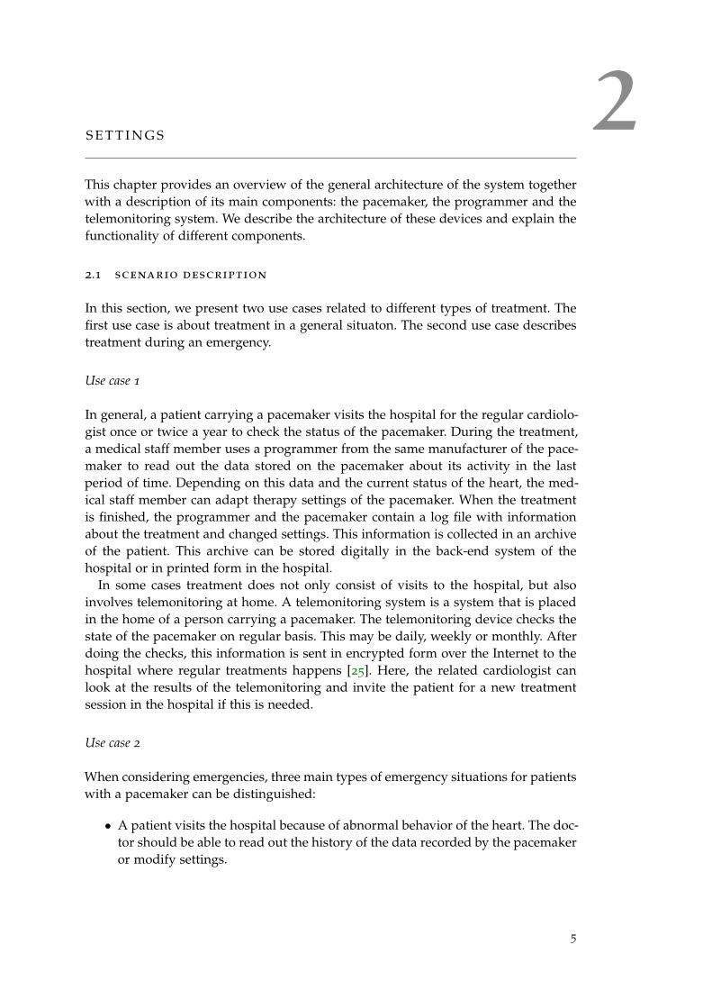
In this section, we present two use cases related to different types of treatment. Thefirst use case is about treatment in a general situaton. The second use case describestreatment during an emergency.
Use case 1
In general, a patient carrying a pacemaker visits the hospital for the regular cardiolo-gist once or twice a year to check the status of the pacemaker. During the treatment,a medical staff member uses a programmer from the same manufacturer of the pace-maker to read out the data stored on the pacemaker about its activity in the lastperiod of time. Depending on this data and the current status of the heart, the med-ical staff member can adapt therapy settings of the pacemaker. When the treatmentis finished, the programmer and the pacemaker contain a log file with informationabout the treatment and changed settings. This information is collected in an archiveof the patient. This archive can be stored digitally in the back-end system of thehospital or in printed form in the hospital.
In some cases treatment does not only consist of visits to the hospital, but alsoinvolves telemonitoring at home. A telemonitoring system is a system that is placedin the home of a person carrying a pacemaker. The telemonitoring device checks thestate of the pacemaker on regular basis. This may be daily, weekly or monthly. Afterdoing the checks, this information is sent in encrypted form over the Internet to thehospital where regular treatments happens [25]. Here, the related cardiologist canlook at the results of the telemonitoring and invite the patient for a new treatmentsession in the hospital if this is needed.
Use case 2
When considering emergencies, three main types of emergency situations for patientswith a pacemaker can be distinguished:
• A patient visits the hospital because of abnormal behavior of the heart. The doc-tor should be able to read out the history of the data recorded by the pacemakeror modify settings.
5
6 settings
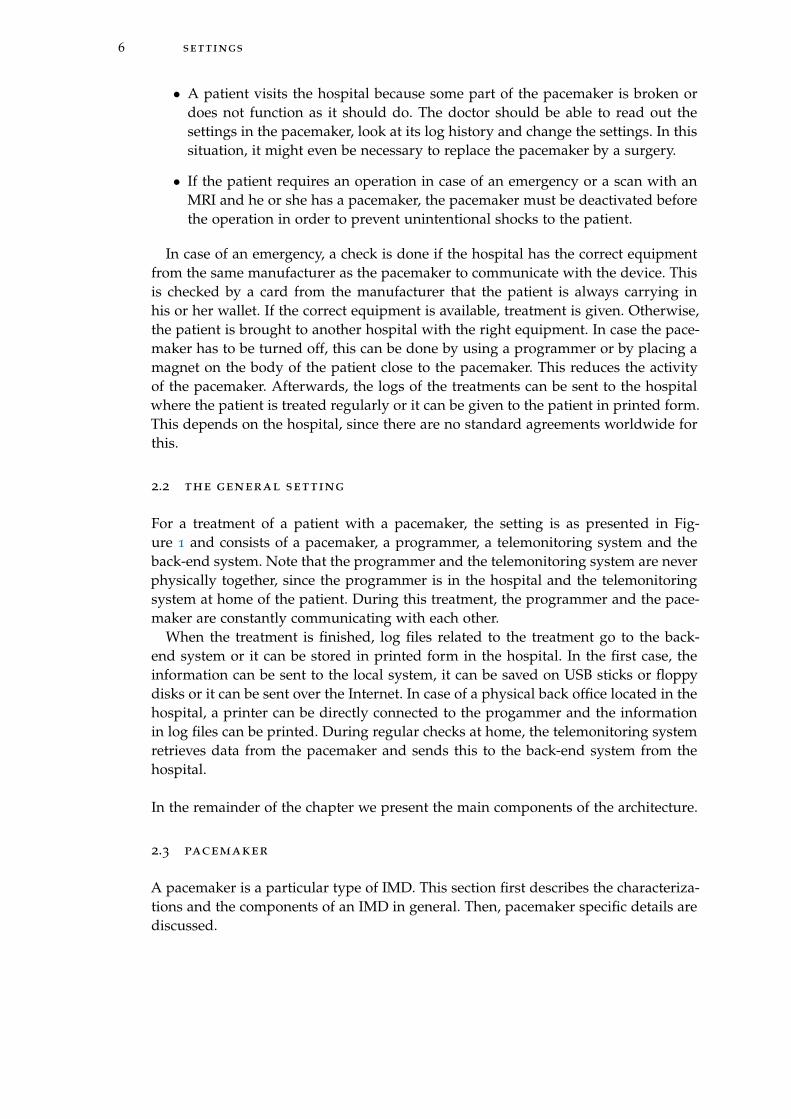
• A patient visits the hospital because some part of the pacemaker is broken ordoes not function as it should do. The doctor should be able to read out thesettings in the pacemaker, look at its log history and change the settings. In thissituation, it might even be necessary to replace the pacemaker by a surgery.
• If the patient requires an operation in case of an emergency or a scan with anMRI and he or she has a pacemaker, the pacemaker must be deactivated beforethe operation in order to prevent unintentional shocks to the patient.
In case of an emergency, a check is done if the hospital has the correct equipmentfrom the same manufacturer as the pacemaker to communicate with the device. Thisis checked by a card from the manufacturer that the patient is always carrying inhis or her wallet. If the correct equipment is available, treatment is given. Otherwise,the patient is brought to another hospital with the right equipment. In case the pace-maker has to be turned off, this can be done by using a programmer or by placing amagnet on the body of the patient close to the pacemaker. This reduces the activityof the pacemaker. Afterwards, the logs of the treatments can be sent to the hospitalwhere the patient is treated regularly or it can be given to the patient in printed form.This depends on the hospital, since there are no standard agreements worldwide forthis.
2.2 the general setting
For a treatment of a patient with a pacemaker, the setting is as presented in Fig-ure 1 and consists of a pacemaker, a programmer, a telemonitoring system and theback-end system. Note that the programmer and the telemonitoring system are neverphysically together, since the programmer is in the hospital and the telemonitoringsystem at home of the patient. During this treatment, the programmer and the pace-maker are constantly communicating with each other.
When the treatment is finished, log files related to the treatment go to the back-end system or it can be stored in printed form in the hospital. In the first case, theinformation can be sent to the local system, it can be saved on USB sticks or floppydisks or it can be sent over the Internet. In case of a physical back office located in thehospital, a printer can be directly connected to the progammer and the informationin log files can be printed. During regular checks at home, the telemonitoring systemretrieves data from the pacemaker and sends this to the back-end system from thehospital.
In the remainder of the chapter we present the main components of the architecture.
2.3 pacemaker
A pacemaker is a particular type of IMD. This section first describes the characteriza-tions and the components of an IMD in general. Then, pacemaker specific details arediscussed.

2.3 pacemaker 7
Figure 1: The general architecture of the current system.
Legend1: The telemonitoring system requests the pacemaker for data and may be able to configurethis device.2: The pacemaker sends its data to the telemonitoring system.3: The telemonitoring forwards the data from the pacemaker to the back-end system of thehospital.4: The programmer configures the pacemaker and requests data stored on the pacemaker.5: The pacemaker sends the data to the programmer.6: The programmer forwards the data to the back-end system of the hospital.7: The back-end system may send data to the programmer about previous treatment sessions.
8 settings
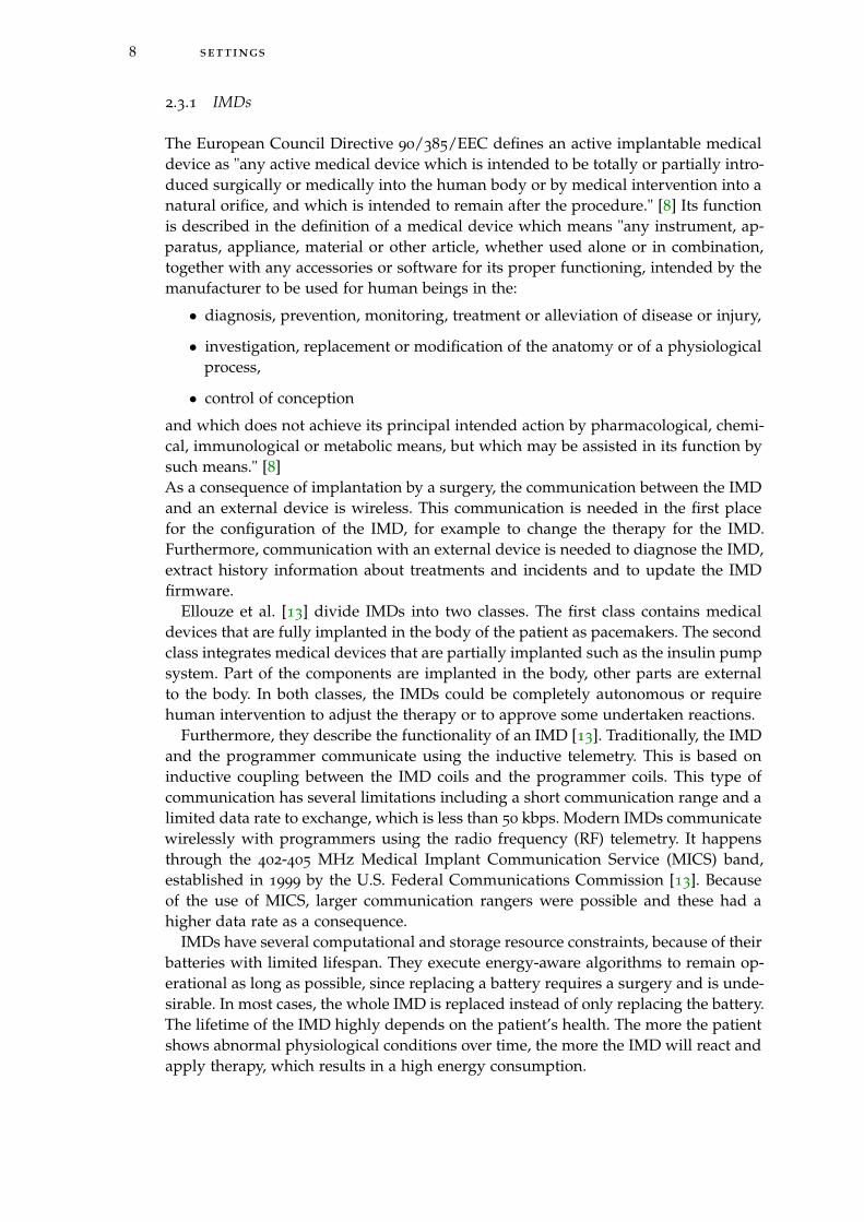
2.3.1 IMDs
The European Council Directive 90/385/EEC defines an active implantable medicaldevice as "any active medical device which is intended to be totally or partially intro-duced surgically or medically into the human body or by medical intervention into anatural orifice, and which is intended to remain after the procedure." [8] Its functionis described in the definition of a medical device which means "any instrument, ap-paratus, appliance, material or other article, whether used alone or in combination,together with any accessories or software for its proper functioning, intended by themanufacturer to be used for human beings in the:
• diagnosis, prevention, monitoring, treatment or alleviation of disease or injury,
• investigation, replacement or modification of the anatomy or of a physiologicalprocess,
• control of conception
and which does not achieve its principal intended action by pharmacological, chemi-cal, immunological or metabolic means, but which may be assisted in its function bysuch means." [8]As a consequence of implantation by a surgery, the communication between the IMDand an external device is wireless. This communication is needed in the first placefor the configuration of the IMD, for example to change the therapy for the IMD.Furthermore, communication with an external device is needed to diagnose the IMD,extract history information about treatments and incidents and to update the IMDfirmware.
Ellouze et al. [13] divide IMDs into two classes. The first class contains medicaldevices that are fully implanted in the body of the patient as pacemakers. The secondclass integrates medical devices that are partially implanted such as the insulin pumpsystem. Part of the components are implanted in the body, other parts are externalto the body. In both classes, the IMDs could be completely autonomous or requirehuman intervention to adjust the therapy or to approve some undertaken reactions.
Furthermore, they describe the functionality of an IMD [13]. Traditionally, the IMDand the programmer communicate using the inductive telemetry. This is based oninductive coupling between the IMD coils and the programmer coils. This type ofcommunication has several limitations including a short communication range and alimited data rate to exchange, which is less than 50 kbps. Modern IMDs communicatewirelessly with programmers using the radio frequency (RF) telemetry. It happensthrough the 402-405 MHz Medical Implant Communication Service (MICS) band,established in 1999 by the U.S. Federal Communications Commission [13]. Becauseof the use of MICS, larger communication rangers were possible and these had ahigher data rate as a consequence.
IMDs have several computational and storage resource constraints, because of theirbatteries with limited lifespan. They execute energy-aware algorithms to remain op-erational as long as possible, since replacing a battery requires a surgery and is unde-sirable. In most cases, the whole IMD is replaced instead of only replacing the battery.The lifetime of the IMD highly depends on the patient’s health. The more the patientshows abnormal physiological conditions over time, the more the IMD will react andapply therapy, which results in a high energy consumption.
2.3 pacemaker 9
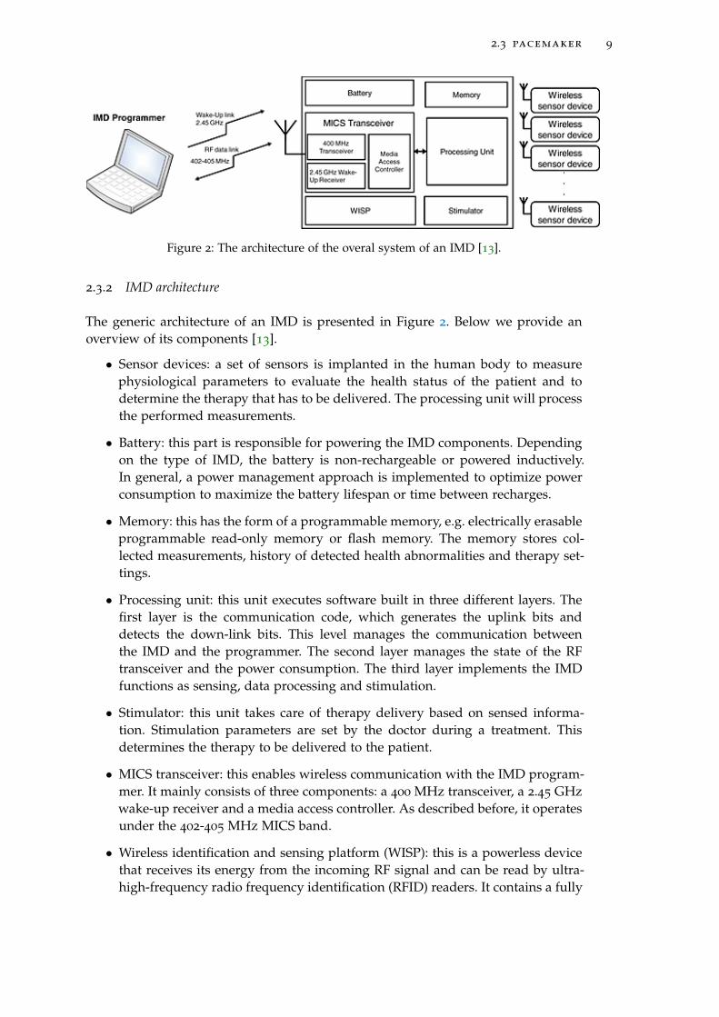
Figure 2: The architecture of the overal system of an IMD [13].
2.3.2 IMD architecture
The generic architecture of an IMD is presented in Figure 2. Below we provide anoverview of its components [13].
• Sensor devices: a set of sensors is implanted in the human body to measurephysiological parameters to evaluate the health status of the patient and todetermine the therapy that has to be delivered. The processing unit will processthe performed measurements.
• Battery: this part is responsible for powering the IMD components. Dependingon the type of IMD, the battery is non-rechargeable or powered inductively.In general, a power management approach is implemented to optimize powerconsumption to maximize the battery lifespan or time between recharges.
• Memory: this has the form of a programmable memory, e.g. electrically erasableprogrammable read-only memory or flash memory. The memory stores col-lected measurements, history of detected health abnormalities and therapy set-tings.
• Processing unit: this unit executes software built in three different layers. Thefirst layer is the communication code, which generates the uplink bits anddetects the down-link bits. This level manages the communication betweenthe IMD and the programmer. The second layer manages the state of the RFtransceiver and the power consumption. The third layer implements the IMDfunctions as sensing, data processing and stimulation.
• Stimulator: this unit takes care of therapy delivery based on sensed informa-tion. Stimulation parameters are set by the doctor during a treatment. Thisdetermines the therapy to be delivered to the patient.
• MICS transceiver: this enables wireless communication with the IMD program-mer. It mainly consists of three components: a 400 MHz transceiver, a 2.45 GHzwake-up receiver and a media access controller. As described before, it operatesunder the 402-405 MHz MICS band.
• Wireless identification and sensing platform (WISP): this is a powerless devicethat receives its energy from the incoming RF signal and can be read by ultra-high-frequency radio frequency identification (RFID) readers. It contains a fully
10 settings
programmable 16 bit microcontroller that is able to execute cryptographic algo-rithms using the harvested energy. Nowadays, only part of the IMDs on themarket carry this component.
• Implantable medical device programmer: this component in the overall archi-tecture of the system is used to communicate with IMDs, to adjust therapy,diagnose the IMD or change its settings.
2.3.3 Pacemaker architecture
A pacemaker is an IMD that delivers a controlled, rhythmic electric stimulus to theheart muscle in order to maintain an effective cardiac rhythm for long periods of time[19]. Implanting a permanent pacemaker and selection of the appropriate mode ofoperation are based on the type of cardiac disease as a failure of impulse formation(sinus syndrome) and/or impulse conduction (AV-block). The connection betweenthe heart and the implanted pulse generator is provided by an implantable electrodecatheter, a lead. This is connected to the heart muscle and serves as a stimulator anda sensor device at the same time. There are different types of pacemakers [21]:
• A Single Chamber Pacemaker: this type has one lead that is placed in the rightupper chamber (atrium) or the lower chamber (ventricle).
• A Dual Chamber Pacemaker: this type has two leads, one in the atrium and onein the ventricle.
• A Biventricular Pacemake: this type has three leads, one in the right atrium,one in the right ventricle and a third in the left ventricle.
• A Rate Responsive Pacemaker: this type of pacemaker adjusts the heart rateto a patient’s level of activity. It paces faster when a patient is exercising andslower when a patient is resting.
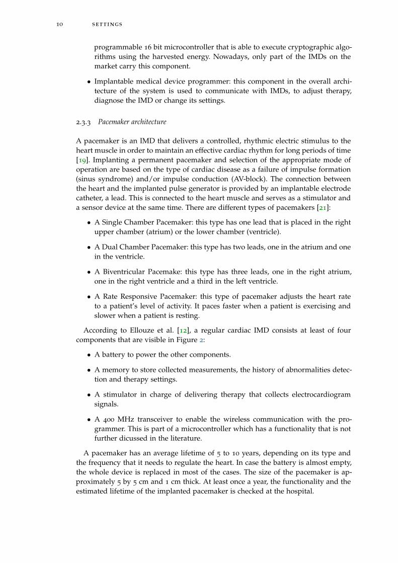
According to Ellouze et al. [12], a regular cardiac IMD consists at least of fourcomponents that are visible in Figure 2:
• A battery to power the other components.
• A memory to store collected measurements, the history of abnormalities detec-tion and therapy settings.
• A stimulator in charge of delivering therapy that collects electrocardiogramsignals.
• A 400 MHz transceiver to enable the wireless communication with the pro-grammer. This is part of a microcontroller which has a functionality that is notfurther dicussed in the literature.
A pacemaker has an average lifetime of 5 to 10 years, depending on its type andthe frequency that it needs to regulate the heart. In case the battery is almost empty,the whole device is replaced in most of the cases. The size of the pacemaker is ap-proximately 5 by 5 cm and 1 cm thick. At least once a year, the functionality and theestimated lifetime of the implanted pacemaker is checked at the hospital.
2.4 programmer 11
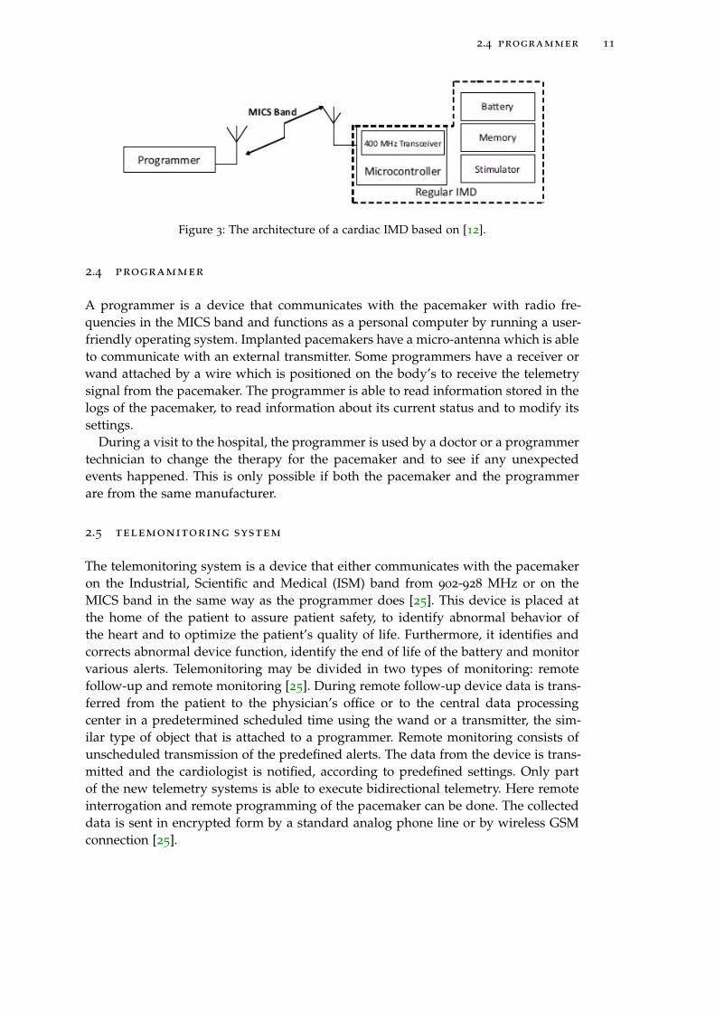
Figure 3: The architecture of a cardiac IMD based on [12].
2.4 programmer
A programmer is a device that communicates with the pacemaker with radio fre-quencies in the MICS band and functions as a personal computer by running a user-friendly operating system. Implanted pacemakers have a micro-antenna which is ableto communicate with an external transmitter. Some programmers have a receiver orwand attached by a wire which is positioned on the body’s to receive the telemetrysignal from the pacemaker. The programmer is able to read information stored in thelogs of the pacemaker, to read information about its current status and to modify itssettings.
During a visit to the hospital, the programmer is used by a doctor or a programmertechnician to change the therapy for the pacemaker and to see if any unexpectedevents happened. This is only possible if both the pacemaker and the programmerare from the same manufacturer.
2.5 telemonitoring system
The telemonitoring system is a device that either communicates with the pacemakeron the Industrial, Scientific and Medical (ISM) band from 902-928 MHz or on theMICS band in the same way as the programmer does [25]. This device is placed atthe home of the patient to assure patient safety, to identify abnormal behavior ofthe heart and to optimize the patient’s quality of life. Furthermore, it identifies andcorrects abnormal device function, identify the end of life of the battery and monitorvarious alerts. Telemonitoring may be divided in two types of monitoring: remotefollow-up and remote monitoring [25]. During remote follow-up device data is trans-ferred from the patient to the physician’s office or to the central data processingcenter in a predetermined scheduled time using the wand or a transmitter, the sim-ilar type of object that is attached to a programmer. Remote monitoring consists ofunscheduled transmission of the predefined alerts. The data from the device is trans-mitted and the cardiologist is notified, according to predefined settings. Only partof the new telemetry systems is able to execute bidirectional telemetry. Here remoteinterrogation and remote programming of the pacemaker can be done. The collecteddata is sent in encrypted form by a standard analog phone line or by wireless GSMconnection [25].

3AT TA C K E R M O D E L A N D C H A L L E N G E S
This chapter gives an overview of the vulnerabilities, threat agents and attacks thatare related to IMDs and are applicable to the pacemaker. Furthermore, challengesrelated to emergency access and energy consumption are presented.
3.1 list of concepts
Based on OWASP [30, 31, 32], we define a vulnerability, a threat agent and an attackas follows:
• Vulnerability: a vulnerability is a hole or weakness in a system that allows anattacker to cause harm to the stakeholders of the system. It can be a design flawor an implementation bug.
• Threat agent: a threat agent is someone who is able to take advantage of a vul-nerability in a system and can cause a negative impact on the system and itsstakeholders.
• Attack: an attack is a sequence of actions a threat agent performs to exploit avulnerability in a system.
3.2 attacker capability model
IBM [2] distinguishes three classes of attackers: clever outsiders, knowledgeable in-siders and funded organizations. Clever outsiders are often intelligent, but may haveinsufficient resources and knowledge of the system. They may have access to onlymoderately sophisticated equipment and they try to take advantage of an existingweakness in the system. Knowledgeable insiders are able to operate on their own,have specialized education and experience and understand parts of the system. Weassume that they have sophisticated tools and instruments for their analysis. Fundedorganizations are able to assemble teams of specialists with related skills by fundingresources. They are able to do in-depth analyses of a system, to design sophisticatedattacks and use advanced analysis tools[2].
In this research, we consider knowledgeable insiders as possible attackers of thepacemaker. They are able to operate on their own, have specialized education andexperience and understand parts of the functionality of the pacemaker and the pro-grammer. They have knowledge about the communication stream between the pro-grammer and the pacemaker, for one or more types of pacemakers. They can buya second hand programmer, for example from eBay or they can steal one from ahospital. Although pacemaker programmers are expensive when offered by the man-ufacturer, several types are available on eBay [11] within the price range from $65 to$1750. They can also use their self made equipment consisting of a Universal SoftwareRadio Peripheral (USRP) [20]. A USRP is commercially available by Ettus Research
13
14 attacker model and challenges
[14] and varies in price range between $675 and $4.800. In both cases, an attacker isable to communicate with a pacemaker according to a certain communication proto-col. Since every manufacturer develops his or her own communication protocol, anattacker will probably not be able to communicate with all types of pacemakers.
3.3 vulnerabilities
The system architecture of the pacemaker and its environment presented in Chapter2 are subject to several vulnerabilities, related to data storage and communication.Considering the pacemaker and the programmer, we can distinguish three types ofmain vulnerabilities:
A The programmer does not require any form of authentication before usage.By turning on a programmer, it can be accessed and controlled by every personwho knows how this programmer works. The only protection provided in cur-rent settings is a form of physical security. Programmer are usually stored in aroom for example with a key that is only carried by authorized medical staffand a security officer. This type of physical security depends on the design ofhospital buildings and the specific policies for each hospital. This is out of thescope of this research.
B The pacemaker does not verify the legitimacy of the programmer.By using a programmer, a communication link with the pacemaker can be estab-lished without using a PIN or any other form of authentication. The pacemakeronly responds to radio frequencies in the range 402-405 MHz without checkingif the device requesting is a programmer and even more specific, a valid pro-grammer. In the logs stored on the pacemaker, there is an option to store whoaccessed the device, but the use of this option depends on the rules set up bythe institution.
C The communication between the programmer and the pacemaker is not encrypted.The data between the programmer and the pacemaker is sent in plaintext. With-out using any form of encryption, privacy sensitive data is sent in the clear andcan become publicly available.
3.4 threats
Threats can be divided in three categories related to the security aspects: confiden-tiality, integrity and availability. Regarding to confidentiality, we can distinguish twotypes of threat agents:
1. Someone who wants to read out data about abnormal physical activities, his-toric treatment or the current status from the pacemaker or programmer. Thishappens by reading the logs.
2. Someone who wants to intercept data on the channel during treatment.
Integrity-related threats are based on the modification of data stored on a device ordata sent during communication. Three types of threat agents can be distinguished:
3.5 attacks 15
3. Someone who wants to change the data in logs stored on the pacemaker or theprogrammer
4. Someone who wants to change the current status of the pacemaker
5. Someone who want to change the data on the channel during treatment
Threats related to availability are important, since the system needs to be available atall times. The two most important availability-related threat agents are:
6. Someone who wants to block the communication channel between the pace-maker and the programmer during treatment
7. Someone who wants to send unnecessary requests to the pacemaker to drainthe battery
3.5 attacks
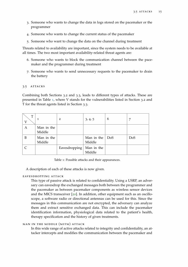
Combining both Sections 3.2 and 3.3, leads to different types of attacks. These arepresented in Table 1, where V stands for the vulnerabilities listed in Section 3.2 andT for the threat agents listed in Section 3.3.
V
T1 2 3, 4, 5 6 7
A Man in theMiddle
B Man in theMiddle
Man in theMiddle
DoS DoS
C Eavesdropping Man in theMiddle
Table 1: Possible attacks and their appearances.
A description of each of these attacks is now given.
eavesdropping attack
This type of passive attack is related to confidentiality. Using a USRP, an adver-sary can eavesdrop the exchanged messages both between the programmer andthe pacemaker as between pacemaker components as wireless sensor devicesand the MICS transceiver [20]. In addition, other equipment such as an oscillo-scope, a software radio or directional antennas can be used for this. Since themessages in this communication are not encrypted, the adversary can analyzethem and extract sensitive exchanged data. This can include the pacemakeridentification information, physiological data related to the patient’s health,therapy specification and the history of given treatments.
man in the middle (mitm) attack
In this wide range of active attacks related to integrity and confidentiality, an at-tacker intercepts and modifies the communication between the pacemaker and
16 attacker model and challenges
the programmer. Related attacks can be executed using a USRP or an unau-thorized programmer. An adversary is able to establish a connection him orherself between a pacemaker and his or her own equipment, if he or she knowsthe communication protocol. After obtaining unauthorized access, an adver-sary could execute unauthorized commands to stop the medical treatment bythe pacemaker, modify the pacemaker’s firmware, drift the pacemaker’s clock,delete data stored on the pacemaker or disable the pacemaker. To make attacksdifficult to detect, attackers could alter, hide or delete data that reveals attacks.These data consist of the log generated by the pacemaker and the pacemaker’sclock that timestamps different logged information. By changing these times-tamps, malicious activity can be seen as part of a regular treatment.
A replay attack is a type of a MITM related to integrity. In this attack, a validdata transmission is maliciously or fraudulently repeated or delayed. By delay-ing messages and changing their order, treatment to the patient can be stopped.Certain request messages from a valid programmer can be overwritten by theequipment from the attacker, when attacking at the correct time.
dos attack
This type of active attack is related to the availability of the pacemaker. Varioustypes of denial-of-service (DoS) attacks can be performed to force the pace-maker to respond to every request. These DoS attacks, as repetitive sendingof request messages to connect to the pacemaker, lead to resource depletionand could drain the pacemaker’s battery. Examples of DoS attacks are jammingattacks and buffer overflow attacks.
By jamming the signal exchanged between the pacemaker and the program-mer, an attacker is able to prevent the pacemaker from receiving the requiredconfiguration or delivering the logged events. In case where the pacemaker isrequired to communicate with wireless sensors, a jamming attack would pre-vent the pacemaker from collecting sensitive events from sensors and it wouldprevent the pacemaker from delivering the adequate therapy or reacting appro-priately.
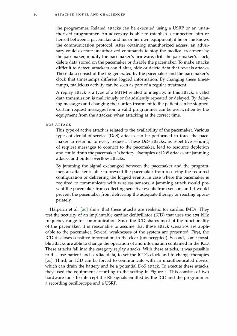
Halperin et al. [20] show that these attacks are realistic for cardiac IMDs. Theytest the security of an implantable cardiac defibrillator (ICD) that uses the 175 kHzfrequency range for communication. Since the ICD shares most of the functionalityof the pacemaker, it is reasonable to assume that these attack scenarios are appli-cable to the pacemaker. Several weaknesses of the system are presented. First, theICD discloses sensitive information in the clear (unencrypted). Second, some possi-ble attacks are able to change the operation of and information contained in the ICD.These attacks fall into the category replay attacks. With these attacks, it was possibleto disclose patient and cardiac data, to set the ICD’s clock and to change therapies[20]. Third, an ICD can be forced to communicate with an unauthenticated device,which can drain the battery and be a potential DoS attack. To execute these attacks,they used the equipment according to the setting in Figure 4. This consists of twohardware tools to intercept the RF signals emitted by the ICD and the programmer:a recording oscilloscope and a USRP.
3.6 challenges for ensuring securing the pacemaker 17
Figure 4: The equipment setting from the research setting [20].
3.6 challenges for ensuring securing the pacemaker
Adding security layers to the communication between the pacemaker and an externaldevice brings several challenges. These are related to emergency access and energyconsumption.
3.6.1 Emergency access
In case of one of the emergency situations as described in Section 2.1, a doctor needsto communicate with the pacemaker using a programmer. With the current pace-maker settings, everyone with a programmer from the same manufacturer as thepacemaker is able to communicate with the pacemaker in an emergency situation.This is undesirable, since attackers can access the pacemaker in this case. In con-trast, if we encrypt all the data in the communication between a programmer and apacemaker and let programmers authenticate to the pacemaker at the start of eachtreatment, unauthorized access would not be possible. However, it is difficult to de-termine who is authorized and how to give right permissions. During general treat-ments, only the cardiologist treating the patient needs authorization. However, incase of an emergency, a medical staff member from another hospital in the samecountry or even abroad needs to get access to the pacemaker to treat the patient. It isundesirable that getting access to the device takes much time.
As a solution, various researchers present fail open access for emergency situations[43]. Here, the pacemaker or another device distinguishes between a regular situationand an emergency situation and provides access for everyone in case of an emergency.However, if an attacker is in proximity of the patient in this situation, he or she isable to access the pacemaker. Burleson et al. [6] claim that a medical professionalmay need to reprogram or disable an IMD to effectively treat the patient in case ofan emergency. Encryption or other authentication mechanisms could make measuresduring emergency impossible if the patient is unconscious or if the programmer doesnot have the required cryptographic key to access the IMD.
3.6.2 Energy consumption
Rostami et al. [38] recognize three ongoing trends related to energy challenges forIMDs. First, IMDs are becoming complex and need more power for new therapeuticand monitoring functionality. Second, the IMDs are collecting more data from new
18 attacker model and challenges
sensors that monitor the patient’s health, which requires power intensive wirelesscommunication. Third, strong security protocols for authentication require the use ofcryptography and require a lot of computation power.
On the one side it is clear that various security aspects of the IMDs should beimproved to protect sensitive data of patients and to provide them with a safe en-vironment. On the other side, improvements in battery lifetime and computationpower needs to be used in improving the functionality of the device, its lifetime andto decrease its size.
Although energy consumption is an important aspect of IMDs, the focus in thisresearch will be more on emergency access. Currently new techniques are coming upand might solve the energy consumption in the very near future. For example, induc-tive charging offers the possibility of relaxing the energy constraints and avoiding thecomplications and costs associated with replacing batteries for medical implants [44].This form of wireless charging is still in a research phase, but can be the future forIMDs. Since emergency access depends less on new technological developments forcomponents in the IMD and is more a challenge for the design of the overall system,we will focus on emergency access in the rest of the research.
4R E L AT E D W O R K
This chapter presents the main trends in the literature related to the security of theIMD and its communication with the programmer. Both solutions for close rangecommunication as for regular communications are presented. For the last category,solutions without a proxy and with a proxy are discussed. Furthermore, solutionsrelated to emergency access are presented.
4.1 close-range communication
To minimize the number of attacks on the radio communication between the IMD andthe programmer, the communication range between the IMD and the programmercan be limited. Several types of solutions have been proposed in this area by Zhang etal. [45]. Radio-frequency identification (RFID) and near-field communication (NFC)are presented as possible solutions, but there exist attacks for these solutions. Anadversary with equipment as a strong transmitter and a high-gain antenna can attacka wireless channel only for RFID-based communication. NFC might be more effective,since it has a working distance up to 20cm. However, there is no guarantee thatan attacker with high-gain antenna cannot read the signal from outside this range.A common used technique, which is also proposed for RFID is distance bounding.Distance-bounding consists of a single-bit challenge and a rapid single-bit response[5]. Based on a series of rapid bit exchanges, a delay time for response is computedby the receiver and can lead to an upper-bound on the distance. Applied to IMDs,this is part of a broader technology called body-coupled communication (BCC) [45].This uses the human body as a transmission medium and its communication rangeis limited to the proximity of the human body. It works at low frequencies from10 kHz to 10 MHz and can only achieve very low data rates. Also measures canbe taken to enforce close-range communication in addition to short-range physicalcommunication layers. However, limiting the communication range is only effectivewhen radio attacks are launched from beyond a certain distance.
Rasmussen et al. [36] state that access control solutions based on close-range com-munication have an advantage of being simple and intuitive, but they do not provideany firm guarantee about the range of communication. If an attacker has a strongtransmitter and a high-gain antenna, he or she will be able to communicate with theIMD from far outside the intended range. Existing solutions are based on magneticswitches, but they do not require any authentication to unlock access. Rasmussen etal. propose a new mechanism based on ultrasonic distance-bounding which enablesan IMD to grant access to its resources only to devices in its close proximity. Mes-sages are cryptographically tied to the distance bounds measured by the IMD, to thedevice that requests access.
The security range defined in the IMD is set to a distance less than 10 cm. Inthis scheme, access control is based on device pairing. During this process, a pairingprotocol will run and will generate a shared key. The reader acts as a prover, who
19
20 related work
has to prove its proximity to start the data transfer. The IMD is the verifier, that mustverify the distance to the prover before accepting the connection.
The system distinguishes two modes of operation: a normal mode and an emer-gency mode. In the normal mode of operation, the credential token that shares asecret key, that the patient carries, is used. When a doctor needs to access the IMD,he or she gets credentials from the patient and provides it to the reader. The proximityaware device pairing protocol runs and afterwards each party has the assurance thatthe other party is in the security range and has derived a key that is used to securefuture communication. The emergency mode of operation is discussed in Section 4.3.
Although MITM attacks are difficult to be executed because of the ultrasonic dis-tance bounding protocol, where a secure pairing is possible only if the reader is ap-proximately 3cm away from the IMD, this solution has some disadvantages accordingto Ellouze et al. [13]. The device pairing protocol requires high energy consumptionto be executed, because of the computational complexity of the Diffie-Hellmann keyagreement protocol. This is undesirable for an IMD. Also, since the solution does nottake the update of parameters into account, they can become vulnerable to cryptanal-ysis attacks when they are used extensively.
4.2 proxy vs non-proxy communication
Several types of solutions for securing the communication between a programmerand an IMD are presented in the literature. These solutions can be divided in twomain categories: solutions without a proxy and solutions with a proxy.
4.2.1 Solutions without a proxy
This type of solutions relies on the implementation of cryptographic algorithms toprotect the communication between a programmer and an IMD. For this purpose,energy-efficient components with computation power are added. Furthermore, theprotocols used for these systems need to be as less energy consuming as possible.Examples of these approaches are using block ciphers, radio frequency energy har-vesting and a smart implant security core. Solutions with these approaches will bediscussed in the following subsections.
4.2.1.1 Block cipher based security
Beck et al. [4] present a block cipher based security protocol with two modes. Astream mode that aims to minimize the radio duty cycle while maintaining basicsecurity and a session mode that provides strong security for highly sensitive infor-mation and a role-based user authorization scheme. The stream mode is used for thetransmission of very short messages and uses the output feedback mode to obtain ascalable stream cipher that enables a strict duty cycling of the IMD’s radio for maxi-mum energy efficiency. The session mode uses cipher-block chaining in combinationwith a challenge response mechanism. This mode is useful when the IMD connects toan external base station. The system provides role-based authorization by assigninga specific private key to each individual user group. This key is linked to a set ofrules that regulate the permitted and prohibited operations of the user.

4.2 proxy vs non-proxy communication 21
Figure 5: A new architecture for cardiac IMDs [12].
The scheme is designed for Artificial Accomodation System. This is a micro-mechatronicimplant meant to replace the natural eye lens in case of a cataract. This IMD shouldhave a duration of 30 years which is very long. As a consequence, the designersshould be aware of threats in the future, which might not be known nowadays. Within30 years, the keysize might be too small because of the computational power of newcomputers. Beck et al. present the solution as meeting all the security and privacyrequirements related to confidentiality, integrity and availability, but they do not giveany proof of this, neither do they present implementation details for the specificdevice. In addition, they do not discuss a solution in case of emergencies.
4.2.1.2 Radio frequency energy harvesting
Ellouze et al. [12] propose a solution based on new components of the architecture ofcardiac IMDs. This would allow the system to perform radio frequency energy har-vesting to enforce secure key generation and authentication. They make use of an en-hanced Wireless Identification and Sensing Platform (WISP) which is able to executecomplex functions using the harvested energy. The IMD programmer is equippedwith an RFID reader to communicate with the WISP and a cardiac sensor to capturethe patient ECG. A powerless mutual-authentication protocol is used to allow secureaccess both in regular situations as in emergency situations. To perform authentica-tion, a biometric key is simultaneously computed by the WISP, embedded in the IMDand the programmer. The key is extracted from the ECG signal and is used to derivemaster and session keys.
A buffer of readings, a WISP and an enhanced programmer with an RFID readerand a set of cardiac sensors are added to the current architecture of the cardiac IMD.The new architecture is presented in Figure 5. The RFID reader is used to interactwith the WISP to execute the powerless mutual authentication protocol. The firsttime the programmer tries to access the IMD, there are no preshared credentials yet.Secure mutual authentication is achieved when the IMD and programmer share abiometric key, which is dynamically and securely generated during access starting
22 related work
Figure 6: A new architecture for IMDs [40].
from the ECG. The regular mode is used when both the IMD and the programmershare the same credentials in a validity period.
After mutual authentication, the devices communicate using a session key, com-puted in the authentication protocol. Each message sent by the programmer containsa cookie to protect against DoS attacks. By using nonces and a sequence number, thefreshness of the message can be determined and the IMD can react in different wayson the type of freshness to improve the life of the battery.
Ellouze et al. claim that their solution is resilient to battery draining attacks, be-cause of their powerless mutual authentication protocol and robustness against de-synchronization attacks and the use of sequence numbers and cookies. Furthermore,their solution prevents against replay attacks, is resilient to brute force attacks andguarantees perfect forward secrecy, which ensures that the compromise of one masterkey will not allow an adversary to predict the subsequent master keys. It is only ableto deduce session keys derived from the compromised master key. Since the architec-ture of the IMD and the programmer needs to be drastically changed and needs tobe tested thoroughly, it is not realistic that this type of IMD will be on the marketwithin a reasonable amount of time.
4.2.1.3 A smart implant security core
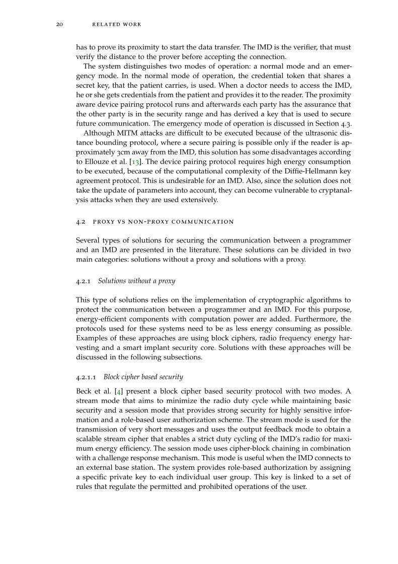
Strydis et al. [40] propose an implant system architecture for an IMD where securityand the main-implant functionality are made decoupled by running the tasks ontwo separate cores. For the wireless communication, a smart implant security core(SISC) is used, which runs an energy efficient security protocol. This core is poweredby RF harvested energy until it performs external-reader authentication to providea defense mechanism against battery DoS attacks and other attacks. The proposedsolution consists of a new system architecture, a secure communication protocol forshielding IMDs and a security processor. Strydis et al. assume jamming attacks neveroccur. Figure 6 presents the architecture of the solution.
For the symmetric encryption scheme, a 64 bit lightweight block cipher MISTY1
is used. This cipher is suitable for implants since it uses low power consumption,low energy cost and a high encryption speed. The system is protected against replayattacks, MITM attacks, eavesdropping attacks and DoS attacks. This solution needs adrastic change of the architecture of the pacemaker and switching to the emergency

4.2 proxy vs non-proxy communication 23
with more access rights is possible in regular situations as explained in Section 4.3.2.Therefore, this solution is not ready for immediate use.
4.2.2 Solutions with a proxy
A technique often presented to preserve battery IMD power is to use a trusted ex-ternal device to verify incoming requests. Because the burden of computation isoffloaded to the external device, this approach can protect the IMD against battery-draining attacks.
4.2.2.1 Communication Cloakers
Denning et al. [10] present the so called Communication Cloakers as a solution. ACloaker is an externally worn device, like a computational Medical Alert bracelet.The general idea of the Cloaker approach is to provide security when the patientis wearing the Cloaker and provide fail-open access to all external programmerswhen the patient is not wearing a Cloaker. In this model, the patient has to wear theCloaker during his or her everyday life. During regular clinic visits, the Cloaker willonly allow pre-specified, authorized commercial programmers to interact with theIMD. The Cloaker acts as a third party mediator in the IMD’s communication withexternal programmers.
The communication between the IMD and the Cloaker would be encrypted byusing symmetric-only cryptography. This to prevent replay and reordering attacks.Then the Cloaker can proxy the communications between the programmer and theIMD or the Cloaker can hand-off a lightweight access credential to the programmer.Since the Cloakers have replaceable batteries and greater computational power thanthe IMD, the Cloaker can take the cryptographic operations on it and its public keys.One of the difficulties is how to detect the Cloaker if it does not have a fixed format.A solution for it is to incorporate a pulse-sensing unit in the Cloaker and define itas being present. There are different approaches for the IMD to detect the Cloaker’spresence. These can be categorized in a stateless approach and a stateful approach.In a stateless approach, the IMD queries the Cloaker when it detects an externalcommunication request. In a stateful approach, the IMD keeps an internal record ofthe Cloaker’s presence and can periodically update this record, based on the presenceor absence of successful keep-alive messages. Both the IMD and the Cloaker caninitiate the keep-alive messages. The use of a Cloaker as a proxy seems promisingand is applied in several solutions that will be discussed in the rest of this subsection.Most of these solutions require no or minimal changes to the architecture of theIMD, which makes them almost directly applicable. Unfortunately, several of thesesolutions are shown to be vulnerable to attacks.
4.2.2.2 A Personal Security Device
Pournaghshband et al. [34] present a Personal Security Device (PSD). This is a portabledevice improving security for mobile medical systems. Its use requires no changesto the medical device or its monitoring software and offers protection for certaintypes of attacks. The PSD should be aware of the suite of wireless mobile medicaldevices used by the owner. Furthermore, it has built-in knowledge of their security
24 related work
Figure 7: The Shield Architecture [17].
properties and vulnerabilities. The PSD augments the security of the owner’s devicesby adding authentication and encryption to data streams. When a medical devicecommunicates with a hospital monitoring system, a PSD can be used as an over-lay between the two components. Here, the link between the PSD and the hospitalmonitoring system can be secured, but the link from the medical device to the PSDremains unsecured. Furthermore, the PSD cannot prevent the device from pairingwith untrusted systems. In this case, the PSD is able to listen to the signals sent bythe device. It is unclear what the PSD does with this information. Although the solu-tion is presented for Bluetooth communication, the idea can be extended to medicaldevices of other radio technologies, by equipping the PSD with that particular radiotechnology capability to connect to the device.
Resulting from their own security analysis, Pournaghshband et al. state that thePSD does not protect against Bluetooth jamming between the PSD and the involvedsystem, but does detect this. The solution is also vulnerable to MITM attacks onthe communication line between the PSD and the device. They state that additionalsecurity mechanisms can prevent this, but this requires altering or rebuilding thedevice.
4.2.2.3 A Medical Security Monitor
Zhang et al. [44] propose a medical security monitor MedMon, that snoops on theradio-frequency wireless communications to or from medical devices. It uses multi-layered anomaly detection to identify transactions that are potentially malicious.MedMon takes response actions ranging from passive to active. It can be appliedto existing medical devices without modifying the hardware or software.
MedMon addresses the loss of integrity, but not the loss of privacy, since the at-tacker may passively listen to transmissions to or from the medical device. Therefore,this solution does not protect against eavesdropping attacks. Furthermore, MedMondoes not address the attacks on availability, since attackers may jam the wirelesschannel rendering any communication impossible or intentionally send invalid pack-ets to drain the device’s battery life. Also, this solution does not consider emergencysituations.
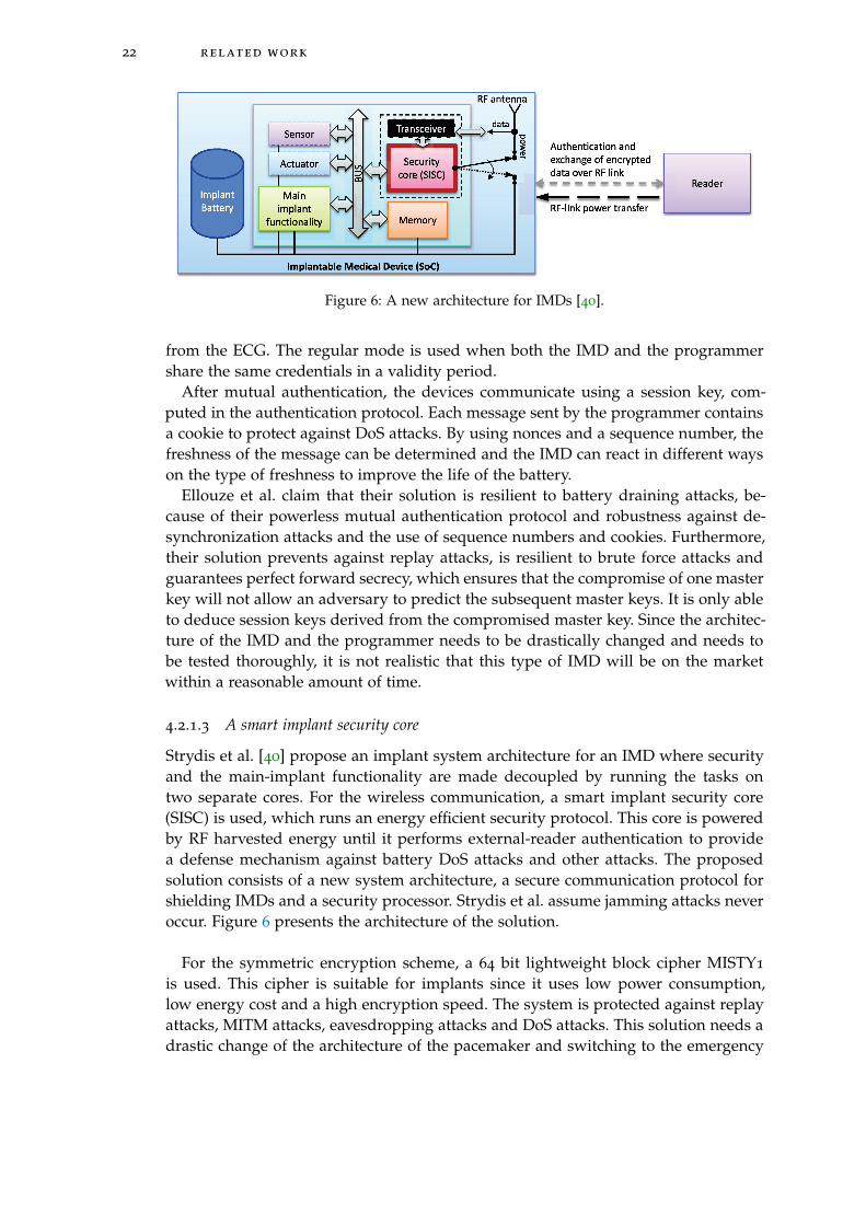
4.2.2.4 The Shield
Gollakota et al. [17] present a design in which an external device, called the shield,is placed between the IMD and the other party (e.g. a programmer). The architec-ture with the shield is shown in Figure 7. The shield can be worn on the body near
4.2 proxy vs non-proxy communication 25
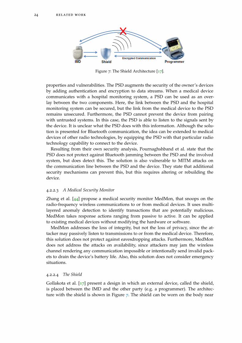
Figure 8: A full duplex radio [17].
an implanted device. It uses a physical-layer mechanism for securing its communi-cation with the IMD and a standard cryptographic channel to communicate withother authorized endpoints. To provide confidentiality for the IMD’s transmissions,the shield continuously listens for those transmissions and jams them so that theycannot be decoded by eavesdroppers. To protect the IMD against commands fromunauthorized endpoints, the shield listens for unauthorized transmissions address-ing the IMD and jams them. A full-duplex radio (Figure 8) is built together witha jamming antenna and a receive antenna, as a small wearable device. This systemprovides both confidentiality for IMD’s transmissions and protects IMDs against com-mands from unauthorized parties, all without modifying the IMD. The shield worksas a relay between the IMD and the programmer. It receives and jams IMD messagesat the same time, so others cannot decode them. It encrypts the IMD message andsends it to the legitimate programmer. All commands from the programmer shouldbe encrypted and sent to the shield first, then the shield sends legitimate commandsto the IMD. In this situation, the IMDs do not need to change in their design, but theprogrammers. Because of the encryption of the communication between the program-mer and the shield and since the messages from the IMD are jammed, confidentialityof the IMD messages is achieved. However, for commands from the programmer tothe IMD, confidentiality is not achieved. Moreover, the full duplex radio does notprovide specific support for access in emergency situations.
Ellouze et al. [13] state that the shield jams every unauthenticated packet, so theverification of its checksum at the IMD level fails. This does not prevent the IMDfrom losing energy to read forged packets. Sending several unauthenticated packetscan have battery draining as a consequence.
4.2.2.5 The IMDGuard
Xu et al. [43] present a solution with an ON/OFF switch to control security protec-tions and switch between emergency and non-emergency situations. They notice twochallenges in this configuration: first, no secret should be pre-deployed inside theIMD. In this way situations where the user is unable to recall the secret and needs torekey the IMD are avoided. Second, there has to be a reliable method to prevent an
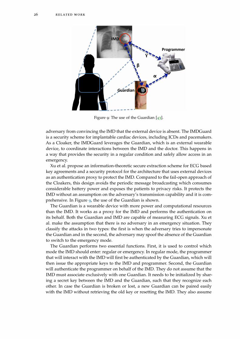
26 related work
Figure 9: The use of the Guardian [43].
adversary from convincing the IMD that the external device is absent. The IMDGuardis a security scheme for implantable cardiac devices, including ICDs and pacemakers.As a Cloaker, the IMDGuard leverages the Guardian, which is an external wearabledevice, to coordinate interactions between the IMD and the doctor. This happens ina way that provides the security in a regular condition and safely allow access in anemergency.
Xu et al. propose an information-theoretic secure extraction scheme for ECG basedkey agreements and a security protocol for the architecture that uses external devicesas an authentication proxy to protect the IMD. Compared to the fail-open approach ofthe Cloakers, this design avoids the periodic message broadcasting which consumesconsiderable battery power and exposes the patients to privacy risks. It protects theIMD without an assumption on the adversary’s transmission capability and it is com-prehensive. In Figure 9, the use of the Guardian is shown.
The Guardian is a wearable device with more power and computational resourcesthan the IMD. It works as a proxy for the IMD and performs the authentication onits behalf. Both the Guardian and IMD are capable of measuring ECG signals. Xu etal. make the assumption that there is no adversary in an emergency situation. Theyclassify the attacks in two types: the first is when the adversary tries to impersonatethe Guardian and in the second, the adversary may spoof the absence of the Guardianto switch to the emergency mode.
The Guardian performs two essential functions. First, it is used to control whichmode the IMD should enter: regular or emergency. In regular mode, the programmerthat will interact with the IMD will first be authenticated by the Guardian, which willthen issue the appropriate keys to the IMD and programmer. Second, the Guardianwill authenticate the programmer on behalf of the IMD. They do not assume that theIMD must associate exclusively with one Guardian. It needs to be initialized by shar-ing a secret key between the IMD and the Guardian, such that they recognize eachother. In case the Guardian is broken or lost, a new Guardian can be paired easilywith the IMD without retrieving the old key or resetting the IMD. They also assume
4.2 proxy vs non-proxy communication 27
that the Guardian has a list of legitimate programmers and their corresponding pub-lic keys that will be used in case of non-emergency mode.
The basic IMD protocol for this system is as follows. The IMD periodically wakesup to determine whether there is a request from the programmer. When the IMDreceives a request, the IMD sends its ID and a random nonce to the programmer andstarts a timer to wait for the Guardian. If the Guardian is present and responds duringthe timer, the regular condition protocol mode will run. When the Guardian doesnot respond before the timer times out, the IMD will run the emergency conditionprotocol.
Rostami et al. [38] show that this protocol is vulnerable to MITM attacks, since theeffective key length of the key used in the encryption can be reduced from 129 bitsto 86 bits. Nowadays, it is possible to brute force this key with available equipment.Furthermore, Ellouze et al. [13] show that the system is vulnerable to DoS attacks, byreplaying a certain response of the guardian. Replayed messages should be decryptedby the IMD before it can decide to reject it or not. With this type of attack, it is possibleto drain the battery.
4.2.2.6 Analysis of proxy-based solutions
Denning et al. [9] study a fundamental gap between the development of technicalmechanisms that could protect the security of medical devices and the security de-fenses that all parties, including the patients and doctors, will accept. They suggestthree relevant security properties for IMDs: authorized clinical access, emergency ac-cess and security in the sense that no unauthorized person should be able to changesettings or view information on the patient’s IMD.
They present four different technical security approaches as a strategy to find thebalance between security for IMDs and safety for the patient in case of an emergency.The first approach consists of using passwords, which is a tradition in the securitycommunity and natural to investigate, but difficult to carry and to access in case ofemergencies. The second category consists of additional patient body modifications,which can be for example a tattoo that serves as a password. The third consists of achange in behavior of the patient, an example of this is to ask the patient to carry anaccess card. The fourth and last approach is passive with respect to the patient. Anexample of this is using biometrics.
Participants are asked for their opinion about the following security mechanisms:medical alert bracelets, visible tattoos, UV-visible tattoos, wristbands, a criticallyaware IMD with no extra modifications and proximity bootstrapping. Although mostmechanisms are clear from their name, proximity bootstrapping needs some furtherexplanation. This system consists of an external device that is used by the medicalstaff. By placing it close to the patient, a temporary key is shared between the deviceand the IMD. Compared to the other ideas, this system does not burden the patient,since he or she does not have to participate in this.
Denning et al. conclude that the password and body modification solutions werethe least favorite. Both the wristband with emergency and warning functionality aspatient passive solutions as proximity bootstrapping were preferred by the patients.One major comment was that participants did not like the idea of wearing or seeingsomething that would remind them of their condition. This could be upsetting. Mostof the participants had difficulties with wearing something all the time under differ-
28 related work
ent conditions. Also cultural and historical associations had as a consequence thatcertain solutions were not liked by the participants. Denning et al. conclude that thepsychological effects of the technology should be minimized.
4.3 emergency access
This section describes several solutions for accessing an IMD in case of an emergency.
4.3.1 Emergency access for close range communication
Rasmussen et al. [36] present a solution for emergency access for proximity basedaccess control. In the emergency mode, it is assumed that the authorization tokenis not available. In most existing systems, wireless communication is only possiblewhen the IMD is activated by a magnetic switch. Rasmussen et al. claim that thesephysical backdoors have many drawbacks. They suggest a new solution in which thesecurity range should be much smaller (2-4 cm) than in the normal mode of opera-tion. If a malicious reader is inside the security range when the IMD is in emergencymode, the reader has free access by design. They state that token-based approacheshave several drawbacks, since it does not protect against the loss or theft of the token.
4.3.2 Emergency access for solutions without a proxy
Ellouze et al. [12] describe that the RFID reader is used to interact with the WISP toexecute the powerless mutual authentication protocol. In emergency situations, thesame way of mutual authentication is used as the first time the programmer tries toaccess the IMD without having preshared credentials. This is achieved when the IMDand programmer share a biometric key, which is dynamically and securely generatedduring access starting from the ECG.
Strydis et al. [40] define a way to get fail-open access in close proximity to theimplant. This is possible by the use of a magnetic switch. They argue that this shouldbe sufficient for next-generation IMDs, but they also state that an adversary mayhave significantly powerful equipment at his or her disposal capable of changing thesecurity mode in case of using a magnetic switch. Also, systems using this techniquemay be prone to accidental mode switching when in presence of relatively strongmagnetic fields.
4.3.3 Emergency access for solutions with a proxy
The Cloaker can be removed from the patient in case of an emergency [10]. When thishappens, the doctor can access the IMD with previously unauthorized commercialprogrammers. By this operation, immediate, emergency open access is enabled.
The Personal Security Device provides a fail-open property in case of an emergency[34]. Unbounded access to the device can be granted by turning off the PSD. Theystate that this mechanism is needed, since life-critical medical devices should alwaysbe available in case of an emergency.
4.3 emergency access 29
Xu et al. [43] present two modes of operation: a regular mode and an emergencymode. If the Guardian is present and responds during the timer, the regular conditionprotocol mode will run. When the Guardian does not respond before the timer timesout, the IMD will run the emergency condition protocol. This means that to get accessto the IMD in case of an emergency, it is sufficient to remove the Guardian from thebody of the patient. During the emergency condition protocol, the IMD checks if theprogrammer is able to send a response that is expected in this emergency mode. Inthis mode, every programmer should be able to communicate with the IMD.
4.3.4 Emergency-based solutions
There are several systems that focus on solutions for emergency situations. In thiscase, no distinction is made between a regular or an emergency mode, but the currentmode is specifically suitable for emergencies.
4.3.4.1 Heart-to-heart
Rostami et al. [39] present the solution Heart-to-heart for emergency situations. Innon-emergency situation, when a patient is receiving routine medical care, they sug-gest the medical personnel to retrieve device-specific keys. In emergency situationsor a situation when a patient is traveling abroad, Heart-to-heart can be usefull for asecondary authentication mechanism. Rostami et al. present a way to use electrocar-diograms (ECG) as an authentication mechanism to ensure that only authorized ex-ternal medical device controllers will make contact with the IMD. A new technique isdeveloped for extracting time-varying randomness from ECG signals together witha new cryptographic device pairing protocol that uses this randomness to protectagainst attacks. In this system, a programmer will make contact with the IMD only ifit has significant physical contact with the patient’s body. Authentication to the IMDlapses once the programmer loses physical contact with the patient. This solution en-forces a touch-to-access policy using a time-varying biometric called a physiologicalvalue (PV). Both the programmer and the IMD take their own reading of the PV. Ifboth readings are nearly equal, the programmer obtains access to the IMD.
The IMD consists of a microcontroller, an ECG analog A/D front end and a wirelesssensor modem, so current IMDs should be modified. Rostami et al. state that theirsystem is secure against jamming and replay attacks, but they only tested brieflyagainst remote heart rate monitoring results. They do not address DoS attacks andeavesdropping.
4.3.4.2 Biometric-based access control
Hei et al. [22] propose a light-weight secure access control scheme for IMDs duringemergencies, using the patient’s biometric information to prevent unauthorized ac-cess to IMDs and to achieve authentication. The scheme consists of two levels. Thefirst one employs some basic biometric information of the patient and is lightweight.This consists of fingerprints’ pattern, height and eye color. The second level utilizedpatient’s iris data for authentication and this combination of two levels should beeffective. Having a low false acceptance rate, a false rejection rate and small memoryand computation overheads, this is presented as a very effective scheme.

30 related work
Because of severe resource constraints of IMDs, as energy supply, processing andstorage, traditional security schemes are not directly applicable. As an example, anIMD from 2002 has only 8kb storage. In this scheme, clinical personnel do not needto have or know a key. They only need devices to measure the biometric propertiesof the patient. In non-emergency situations, an IMD reader needs to pass an authen-tication process in order to access an IMD.
Hei et al. see that in emergency situations, biometric data can be destroyed, asfingerprints in case of a fire. However, they assume that in this case, help for theIMD is secondary and other medical treatments are more important. Because of thelack of cryptography, it is possible to eavesdrop during communication between anIMD and a programmer. Furthermore, no technique is used to prevent DoS attacks.However, iris image verification technique is unpractical, because a specific camerais required to capture the patient’s iris [13]. In addition, eye illnesses for aged peoplecan cause many false positives and negatives during authentication of the patient’sIMD.
4.3.5 Break-The-Glass
Break-The-Glass suggests to use a system with maximum freedom and maximumresponsibility [16]. Maximum freedom stands for the property that the system mustprovide mechanisms for the users to access the requested information at all times,whenever it is needed. Maximum responsibility means that the system must providemechanisms to show the user an alert message, when he or she is trying to accessinformation he or she is not authorized to see.
Ferreira et al. [16] state that the BTG principle can be implemented in the followingway. When a user does a request to the system, the authorization model verifieswhether the user has access to the requested information. If the model returns ’yes’,the user gets immediate access. In case of ’no’, the user is shown that he or shecan still break the glass and he or she will be notified that all his or her actions arerecorded from then. The user decides to break the glass or leave the system. In caseof breaking, a hierarchy model verifies who has to be notified and continues. Fromthen all notifications and user actions are registered automatically.
4.4 discussion
In this chapter, several solutions for securing the IMD are presented. For each sys-tem, we looked at the architecture of the system and its functionality compared tothe architecture described in Chapter 2, its resistance against the attacks mentionedin Chapter 3 and the way it handles emergency access. In the next three table, wecompared the aspects of the architecture, attacks and the emergency mode for tensystems described in this chapter. Table 2 shows that only solutions with a change inthe hardware components of the IMD are able to prevent against battery draining. Innone of the systems that use a proxy, it is possible to prevent battery draining. It isalso remarkable that four out of ten system do not talk about battery draining at all.This suggests that the designer of the new system did not take this into considerationand the system will probaly not be able to prevent battery draining attacks.

4.4 discussion 31
We can conclude that no current system is able to prevent all the five types ofattacks. It is remarkable that only two systems consider all types of attacks and thatmost systems only worry about active attacks and do not take eavesdropping intoaccount. Because of this, it is hard to get an overview of all types of systems andtheir possibilities. Furthermore, only half of the systems have proofs for some securityaspects. Other systems state that they are secure against certain types of attacks, bygiving an indication or without further explanation. From this, we can conclude thatcurrent research lacks in considering all relevant security aspects.
From the table, we can see that most systems have an emergency mode whereweaker or less security is used. Three systems do not have a specific emergencymode and will operate in their regular mode during emergencies. The differencesand similarities between the security modes of the systems are hard to describe,since some systems only state that there is an emergency mode or shortly give adescription, while others give extensive protocols. It is hard to compare these differ-ent approaches.

32
re
la
te
dw
or
k
Table 2: A comparison of existing solutions.
Legendn/a: not mentioned in the research
V: proven to be protectedV*: stated to be protected
x: vulnerable
Properties
SystemsProximity Block cipher RF energy harvesting SISC PSD MedMon The Shield IMDGuard H2H Biometric
Using a proxy no no no no yes yes yes yes no no
Battery draining V* n/a V V n/a x x x n/a n/a
Modify the IMD hardware no no yes yes no no no no yes no
Emergency mode yes no yes yes yes no no yes yes yes
Eavesdropping attacks n/a n/a n/a V* n/a x V n/a n/a n/a
MITM attacks V* n/a n/a V* x V n/a x V* n/a
Replay attacks V* n/a V V n/a V* n/a V* V* n/a
DoS attacks V* n/a V V x x n/a x n/a n/a
Jamming attacks n/a n/a n/a x x x V V V* n/a
5R E Q U I R E M E N T S A N D A S S U M P T I O N S
In this chapter, we define all assumptions and requirements for an optimal systemsolution. Assumptions and requirements are categorized in the categories general,emergency access and energy consumption. We show that these requirements aredifficult to implement at the same time. For this reason, two types of system solutionsare introduced at the end of this chapter.
5.1 general assumptions
The assumptions for an optimal solution are listed in Table 3. All assumptions aregeneral asumptions (GA) and are not related to emergency access and energy con-sumption. These general assumptions are based on how the system works and onthe environment where the systems are used.
For GA1, the first assumption in Table 3, we assume that programmers are storedin a locked room that is only accessible by authorized medical staff. They are onlyused by the staff that is authorized to treat patients and is trusted. GA2 is about thelocation where the patient is treated. We assume that the patient is treated in thesame hospital for regular treatments. GA3 assumes that no medical staff memberwill misuse a valid programmer on purpose to change the behavior of the pacemaker.Staff members are authorized and screened beforehand. GA4 assumes that the hos-pital makes use of a back-end system. This can be a local system or can be connectedto the Internet. Details about the security of a connection from the back-end to theInternet are out of the scope of this research. This back-end system is needed to storethe cryptographic keys. In case of the use of a telemonitoring system at the home ofthe patient, the back-end system needs to be reached by the telemonitoring systemover the Internet. GA5 is about contact between a patient and an attacker. Attacks onpatients where the attacker can touch the patient and that will have consequences onthe pacemaker or its behavior are out of scope. GA6 is based on the fact that the Fed-eral Communications Commission [15] stated that a transmission is always startedby a device external to the body. GA7 assumed that a treatment takes place once in 6
to 9 months, but it can happen more frequently if necessary.
5.2 requirements for an optimal solution
For an optimal solution, we can define various requirements. General requirements(GR) are based on security principles and on the environment where the systemsare used. They should hold in general situations and during general treatments, butnot during emergencies. Requirements for emergency access (ER) and energy con-sumption (ECR) are based on the challenges presented in Chapter 3. A list of all therequirements is presented in Table 4.
GR1, GR2 and GR3 are related to access by authorized entities. The programmershould only communicate with a pacemaker implanted in a patient’s body. More im-
33
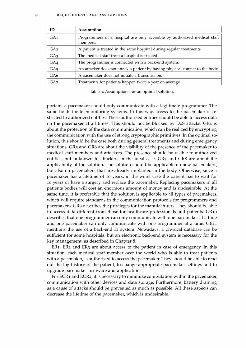
34 requirements and assumptions
ID Assumption
GA1 Programmers in a hospital are only accesible by authorized medical staffmembers.
GA2 A patient is treated in the same hospital during regular treatments.
GA3 The medical staff from a hospital is trusted.
GA4 The programmer is connected with a back-end system.
GA5 An attacker does not attack a patient by having physical contact to the body.
GA6 A pacemaker does not initiate a transmission.
GA7 Treatments for patients happen twice a year on average.
Table 3: Assumptions for an optimal solution.
portant, a pacemaker should only communicate with a legitimate programmer. Thesame holds for telemonitoring systems. In this way, access to the pacemaker is re-stricted to authorized entities. These authorized entities should be able to access dataon the pacemaker at all times. This should not be blocked by DoS attacks. GR4 isabout the protection of the data communication, which can be realized by encryptingthe communication with the use of strong cryptographic primitives. In the optimal so-lution, this should be the case both during general treatments and during emergencysituations. GR5 and GR6 are about the visibility of the presence of the pacemaker tomedical staff members and attackers. The presence should be visible to authorizedentities, but unknown to attackers in the ideal case. GR7 and GR8 are about theapplicability of the solution. The solution should be applicable on new pacemakers,but also on pacemakers that are already implanted in the body. Otherwise, since apacemaker has a lifetime of 10 years, in the worst case the patient has to wait for10 years or have a surgery and replace the pacemaker. Replacing pacemakers in allpatients bodies will cost an enormous amount of money and is undesirable. At thesame time, it is preferable that the solution is applicable to all types of pacemakers,which will require standards in the communication protocols for programmers andpacemakers. GR9 describes the privileges for the manufacturers. They should be ableto access data different from those for healthcare professionals and patients. GR10
describes that one programmer can only communicate with one pacemaker at a timeand one pacemaker can only communicate with one programmer at a time. GR11
mentions the use of a back-end IT system. Nowadays, a physical database can besufficient for some hospitals, but an electronic back-end system is necessary for thekey management, as described in Chapter 8.
ER1, ER2 and ER3 are about access to the patient in case of emergency. In thissituation, each medical staff member over the world who is able to treat patientswith a pacemaker, is authorized to access the pacemaker. They should be able to readout the log history of the patient, to change appropriate pacemaker settings and toupgrade pacemaker firmware and applications.
For ECR1 and ECR2, it is necessary to minimize computation within the pacemaker,communication with other devices and data storage. Furthermore, battery drainingas a cause of attacks should be prevented as much as possible. All these aspects candecrease the lifetime of the pacemaker, which is undesirable.
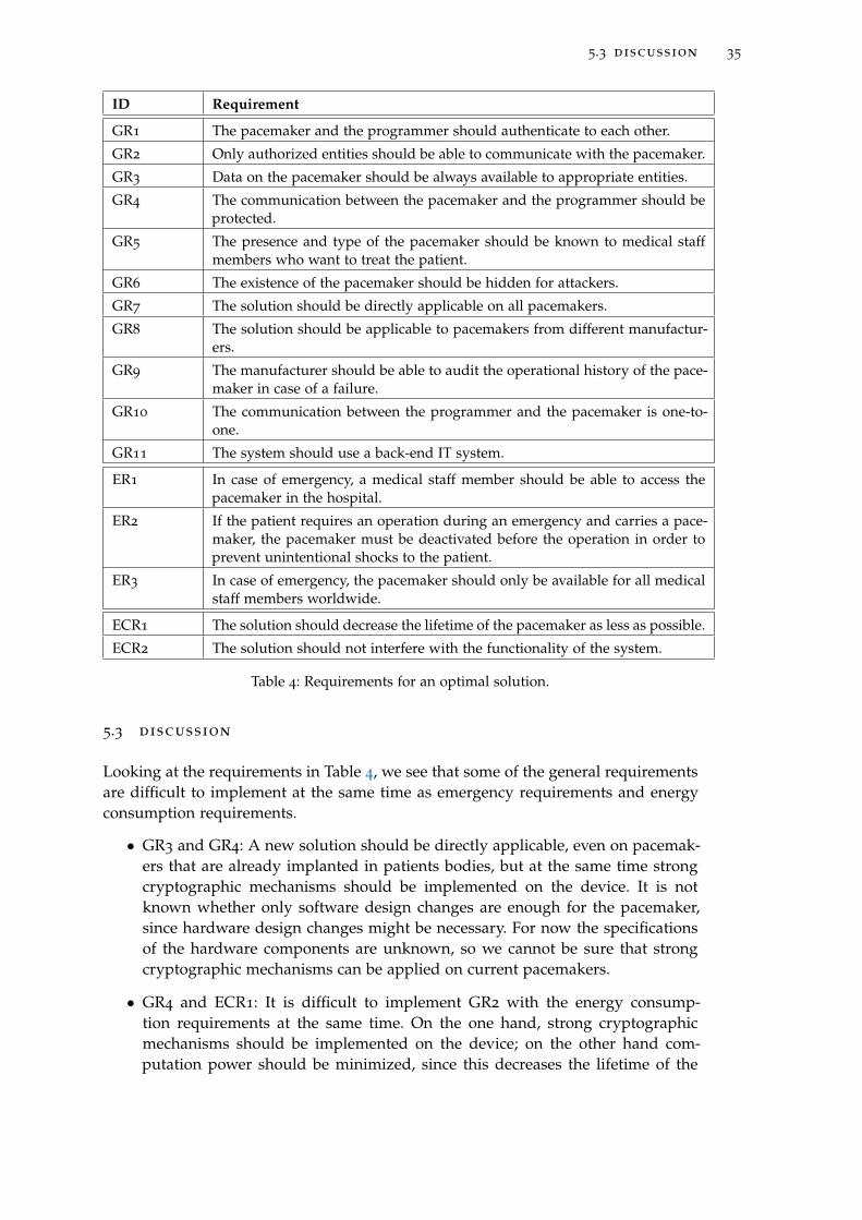
5.3 discussion 35
ID Requirement
GR1 The pacemaker and the programmer should authenticate to each other.
GR2 Only authorized entities should be able to communicate with the pacemaker.
GR3 Data on the pacemaker should be always available to appropriate entities.
GR4 The communication between the pacemaker and the programmer should beprotected.
GR5 The presence and type of the pacemaker should be known to medical staffmembers who want to treat the patient.
GR6 The existence of the pacemaker should be hidden for attackers.
GR7 The solution should be directly applicable on all pacemakers.
GR8 The solution should be applicable to pacemakers from different manufactur-ers.
GR9 The manufacturer should be able to audit the operational history of the pace-maker in case of a failure.
GR10 The communication between the programmer and the pacemaker is one-to-one.
GR11 The system should use a back-end IT system.
ER1 In case of emergency, a medical staff member should be able to access thepacemaker in the hospital.
ER2 If the patient requires an operation during an emergency and carries a pace-maker, the pacemaker must be deactivated before the operation in order toprevent unintentional shocks to the patient.
ER3 In case of emergency, the pacemaker should only be available for all medicalstaff members worldwide.
ECR1 The solution should decrease the lifetime of the pacemaker as less as possible.
ECR2 The solution should not interfere with the functionality of the system.
Table 4: Requirements for an optimal solution.
5.3 discussion
Looking at the requirements in Table 4, we see that some of the general requirementsare difficult to implement at the same time as emergency requirements and energyconsumption requirements.
• GR3 and GR4: A new solution should be directly applicable, even on pacemak-ers that are already implanted in patients bodies, but at the same time strongcryptographic mechanisms should be implemented on the device. It is notknown whether only software design changes are enough for the pacemaker,since hardware design changes might be necessary. For now the specificationsof the hardware components are unknown, so we cannot be sure that strongcryptographic mechanisms can be applied on current pacemakers.
• GR4 and ECR1: It is difficult to implement GR2 with the energy consump-tion requirements at the same time. On the one hand, strong cryptographicmechanisms should be implemented on the device; on the other hand com-putation power should be minimized, since this decreases the lifetime of the
36 requirements and assumptions
pacemaker. Cryptographic mechanisms require of a lot of computations, so theperformance of various hardware components should be improved to maintainthe current lifetime of the pacemaker.
• GR3 and ER1 and ER3: On the one hand, the data should be always availableto authorized entities, in general the cardiologist and pacemaker technicianswho treat the patient. However, the number of authorized entities should beextended in case of an emergency. It is difficult to make medical staff membersauthorized entities and to give them access. It is possible to extend authoriza-tion to more medical staff member in the hospital where the patient gets his orher regular treatments, but for medical staff in other hospitals and even in othercountries, this is a challenge. In this situation, we have to deal with differenttrust domains which makes it harder. At the moment, there is no worldwidemedical database that could save this type of information and this probablywill not be there on short term.
Because of these issues, we need to make some trade-offs and thus we present twosolutions to solve this problem. The first solution presented in Chapter 6 is a solu-tion which is directly implementable for implanted pacemakers. This solution makesuse of a proxy which is placed between the programmer and the pacemaker. Thisproxy contains a jammer, which only allows communication between the proxy andthe pacemaker but blocks all the traffic from other devices to the pacemaker. Withoutusing any form of encryption of the communication between the proxy and the pace-maker, this solution does not require any changes of the design of the pacemaker.Encryption of the communication between the proxy and the programmer is needed.In the next chapter, we present the system design of the solution together with thedesign of the proxy and the security protocol for the communication between theprogrammer and the proxy. We also present a solution for access in emergency situa-tions.
In Chapter 7, we present a solution which does not require the use of the proxy.The use of an external device is undesirable, because it can be lost, stolen, broken orforgotten by the patient. We define a security protocol together with an analysis of itscorrectness and we make an analysis on the ciphers that may be used in combinationwith the protocol.
Important part of both solutions is key management. Key generation methods de-pend on the capability of devices, which is not straightforward for resource con-strained devices. The management of these keys requires that keys are stored on asafe place. Since programmers can contain malware, this is not an appropriate placeto store them. Furthermore, in emergency situations the pacemaker should still beavailable. In Chapter 8, details about key management are discussed and Chapter9 presents a new emergency access solution which does not use the cryptographickeys.
6P R O X Y- B A S E D S O L U T I O N
In this chapter, we present our solution that is directly applicable on already im-planted pacemakers. By making use of a proxy, secure communication can be guar-anteed, except for emergency situations where fail open access is provided. Togetherwith our formulated assumptions and requirements for this solution, the architec-ture of the system is presented including the technical requirements of the proxy.Furthermore, a security protocol is presented that is used for the communication be-tween the proxy and the programmer. In Chapter 8, we present details about the keymanagement for this solution.
6.1 assumptions
For this proxy-based solution all general assumptions (GA1 to GA7) from Section 4.1hold, since these are listed as general assumptions. A few additional assumptionshave to be made related to the design of the new system and the fact that it should bepossible to implement this immediately on already implanted devices. The assump-tions concern the use of a proxy (PA) and emergency access (PEA). These additionalassumptions are presented in Table 5.
PA1 requires a setting in which the distance between the proxy and the pacemakeris small. This is necessary to prevent that the pacemaker willl communicate withother devices than the proxy. This can be achieved when the proxy has the form ofa necklace for example. PA2 is an extension of GA5, in which an attacker does notphysically attack a patient. PEA1 can be assumed for now, since treatment is given ina hospital environment. An attacker carrying his or her own equipment in a hospitalwill be noticed, since current equipment is too large to hide. It is possible that in thefuture this may no longer be true.
6.2 requirements
Considering the requirements presented in Table 4, we can state the following. Thegeneral requirements that hold are GR1, GR2, GR4, GR5, GR7, GR8, GR9 and GR11.The proxy-based solution is able to meet all these requirements. This will becomeclear in the following sections of this chapter when the architecture and securitymechanisms are discussed. There are two requirements GR3 and GR6 that cannot berealized. GR3 has to do with the availability of the pacemaker, which cannot be guar-anteed because of possible DoS attacks. This system does not have a mechanism toprevent all types of DoS attacks. Although the proxy can be made in a way that an at-tacker does not notice the necklace, an attacker with the right equipment does noticethe pacemaker, even when he or she is not able to authenticate. GR6 is not achieved,since attackers will always notice the existence of the pacemaker, when they have theright equipment. GR10 is replaced by requirement PGR2 presented in Table 6, sinceGR10 does not consider the existence of a proxy. PGR2 dscribes the communication
37
38 proxy-based solution
ID Assumption
PA1 The proxy is a wearable device located close to the pacemaker.
PA2 The attacker does not try to physically remove the proxy.
PEA1 There is very little chance an attacker is around during an emergency treat-ment.
Table 5: Assumptions for a proxy-based solution
ID Requirement
PGR1 All communication between a programmer and a pacemaker should pass theproxy.
PGR2 The communication between the programmer and the proxy is one-to-oneduring a treatment session.
PGR3 The communication between the pacemaker and the proxy is one-to-one.
PTR1 The proxy is able to execute cryptographic operations and to store crypto-graphic keys.
PTR2 The programmer is able to execute cryptographic operations.
PTR3 The back-end should store cryptographic keys.
Table 6: Requirements for a proxy-based solution.
between the programmer and a proxy during a treatment session. In a session, a pro-grammer can only communicate with one proxy and a proxy can only communicatewith one programmer at the same time. PGR3 states that the communication betweena pacemaker and a proxy is always one-to-one. This has to do with the fact that thesedevices are linked to each other during the first treatment. Both ER1 and ER2 hold,since the pacemaker can be accessed by everyone in case of an emergency situation.This has to do with the architecture of the system and is explained in the next sec-tion. ER3 does not hold, since an attacker also has access during an emergency. Bothenergy consumption related requirements ECR1 and ECR2 hold because the proxytakes over the heavy computations from the pacemaker.
The following general requirements (PGR) and technical requirements (PTR) in Ta-ble 6 are added because of the use of a proxy. The general requirements are generalin the sense that they are applicable on general situations and during general treat-ments. They do not hold during emergencies.
Note that the requirements for the programmer also hold for the telemonitoringsystem. PGR1 specifies how the communication goes between the programmer, proxyand pacemaker. The proxy should block the traffic to the pacemaker from othersources than itself. The proxy has the task to only let the pacemaker indirectly com-municate with authorized entities. The architecture is further explained in the nextsection. PGR2 describes that one programmer can only communicate with one proxyat the time and one proxy can only communicate with one programmer at the time.This is comparable with GR10, which describes the same for the pacemaker insteadof the proxy. PTR1 and PTR2 require specific technical functionalities to provide au-thentication and secure communication both for the proxy and the programmer. As
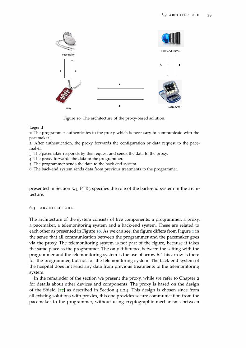
6.3 architecture 39
Figure 10: The architecture of the proxy-based solution.
Legend1: The programmer authenticates to the proxy which is necessary to communicate with thepacemaker.2: After authentication, the proxy forwards the configuration or data request to the pace-maker.3: The pacemaker responds by this request and sends the data to the proxy.4: The proxy forwards the data to the programmer.5: The programmer sends the data to the back-end system.6: The back-end system sends data from previous treatments to the programmer.
presented in Section 5.3, PTR3 specifies the role of the back-end system in the archi-tecture.
6.3 architecture
The architecture of the system consists of five components: a programmer, a proxy,a pacemaker, a telemonitoring system and a back-end system. These are related toeach other as presented in Figure 10. As we can see, the figure differs from Figure 1 inthe sense that all communication between the programmer and the pacemaker goesvia the proxy. The telemonitoring system is not part of the figure, because it takesthe same place as the programmer. The only difference between the setting with theprogrammer and the telemonitoring system is the use of arrow 6. This arrow is therefor the programmer, but not for the telemonitoring system. The back-end system ofthe hospital does not send any data from previous treatments to the telemonitoringsystem.
In the remainder of the section we present the proxy, while we refer to Chapter 2
for details about other devices and components. The proxy is based on the designof the Shield [17] as described in Section 4.2.2.4. This design is chosen since fromall existing solutions with proxies, this one provides secure communication from thepacemaker to the programmer, without using cryptographic mechanisms between
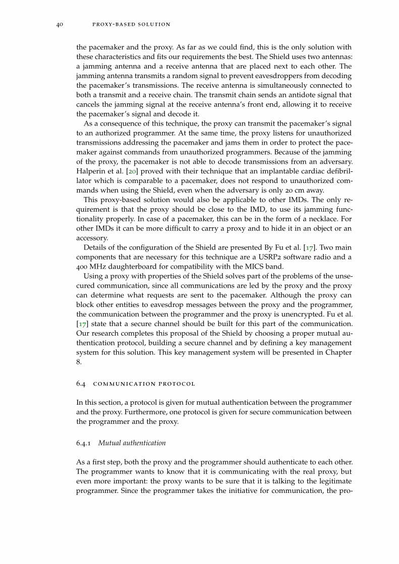
40 proxy-based solution
the pacemaker and the proxy. As far as we could find, this is the only solution withthese characteristics and fits our requirements the best. The Shield uses two antennas:a jamming antenna and a receive antenna that are placed next to each other. Thejamming antenna transmits a random signal to prevent eavesdroppers from decodingthe pacemaker’s transmissions. The receive antenna is simultaneously connected toboth a transmit and a receive chain. The transmit chain sends an antidote signal thatcancels the jamming signal at the receive antenna’s front end, allowing it to receivethe pacemaker’s signal and decode it.
As a consequence of this technique, the proxy can transmit the pacemaker’s signalto an authorized programmer. At the same time, the proxy listens for unauthorizedtransmissions addressing the pacemaker and jams them in order to protect the pace-maker against commands from unauthorized programmers. Because of the jammingof the proxy, the pacemaker is not able to decode transmissions from an adversary.Halperin et al. [20] proved with their technique that an implantable cardiac defibril-lator which is comparable to a pacemaker, does not respond to unauthorized com-mands when using the Shield, even when the adversary is only 20 cm away.
This proxy-based solution would also be applicable to other IMDs. The only re-quirement is that the proxy should be close to the IMD, to use its jamming func-tionality properly. In case of a pacemaker, this can be in the form of a necklace. Forother IMDs it can be more difficult to carry a proxy and to hide it in an object or anaccessory.
Details of the configuration of the Shield are presented By Fu et al. [17]. Two maincomponents that are necessary for this technique are a USRP2 software radio and a400 MHz daughterboard for compatibility with the MICS band.
Using a proxy with properties of the Shield solves part of the problems of the unse-cured communication, since all communications are led by the proxy and the proxycan determine what requests are sent to the pacemaker. Although the proxy canblock other entities to eavesdrop messages between the proxy and the programmer,the communication between the programmer and the proxy is unencrypted. Fu et al.[17] state that a secure channel should be built for this part of the communication.Our research completes this proposal of the Shield by choosing a proper mutual au-thentication protocol, building a secure channel and by defining a key managementsystem for this solution. This key management system will be presented in Chapter8.
6.4 communication protocol
In this section, a protocol is given for mutual authentication between the programmerand the proxy. Furthermore, one protocol is given for secure communication betweenthe programmer and the proxy.
6.4.1 Mutual authentication
As a first step, both the proxy and the programmer should authenticate to each other.The programmer wants to know that it is communicating with the real proxy, buteven more important: the proxy wants to be sure that it is talking to the legitimateprogrammer. Since the programmer takes the initiative for communication, the pro-
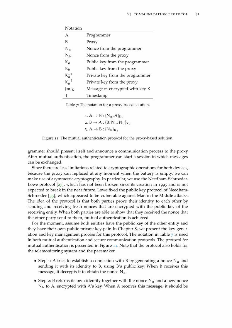
6.4 communication protocol 41
Notation
A Programmer
B Proxy
Na Nonce from the programmer
Nb Nonce from the proxy
Ka Public key from the programmer
Kb Public key from the proxy
K−1a Private key from the programmer
K−1b Private key from the proxy
{m}K Message m encrypted with key K
T Timestamp
Table 7: The notation for a proxy-based solution.
1. A→ B : {Na,A}Kb
2. B→ A : {B,Na,Nb}Ka
3. A→ B : {Nb}Kb
Figure 11: The mutual authentication protocol for the proxy-based solution.
grammer should present itself and announce a communication process to the proxy.After mutual authentication, the programmer can start a session in which messagescan be exchanged.
Since there are less limitations related to cryptographic operations for both devices,because the proxy can replaced at any moment when the battery is empty, we canmake use of asymmetric cryptography. In particular, we use the Needham-Schroeder-Lowe protocol [27], which has not been broken since its creation in 1995 and is notexpected to break in the near future. Lowe fixed the public key protocol of Needham-Schroeder [35], which appeared to be vulnerable against Man in the Middle attacks.The idea of the protocol is that both parties prove their identity to each other bysending and receiving fresh nonces that are encrypted with the public key of thereceiving entity. When both parties are able to show that they received the nonce thatthe other party send to them, mutual authentication is achieved.
For the moment, assume both entities have the public key of the other entity andthey have their own public-private key pair. In Chapter 8, we present the key gener-ation and key management process for this protocol. The notation in Table 7 is usedin both mutual authentication and secure communication protocols. The protocol formutual authentication is presented in Figure 11. Note that the protocol also holds forthe telemonitoring system and the pacemaker.
• Step 1: A tries to establish a connection with B by generating a nonce Na andsending it with its identity to B, using B’s public key. When B receives thismessage, it decrypts it to obtain the nonce Na.
• Step 2: B returns its own identity together with the nonce Na and a new nonceNb to A, encrypted with A’s key. When A receives this message, it should be
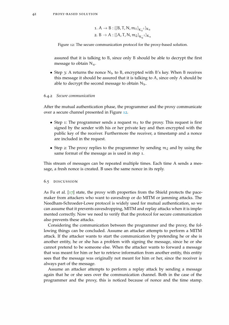
42 proxy-based solution
1. A→ B : {{B, T ,N,m1}K−1a}Kb
2. B→ A : {{A, T ,N,m2}K−1b}Ka
Figure 12: The secure communication protocol for the proxy-based solution.
assured that it is talking to B, since only B should be able to decrypt the firstmessage to obtain Na.
• Step 3: A returns the nonce Nb to B, encrypted with B’s key. When B receivesthis message it should be assured that it is talking to A, since only A should beable to decrypt the second message to obtain Nb.
6.4.2 Secure communication
After the mutual authentication phase, the programmer and the proxy communicateover a secure channel presented in Figure 12.
• Step 1: The programmer sends a request m1 to the proxy. This request is firstsigned by the sender with his or her private key and then encrypted with thepublic key of the receiver. Furthermore the receiver, a timestamp and a nonceare included in the request.
• Step 2: The proxy replies to the programmer by sending m2 and by using thesame format of the message as is used in step 1.
This stream of messages can be repeated multiple times. Each time A sends a mes-sage, a fresh nonce is created. B uses the same nonce in its reply.
6.5 discussion
As Fu et al. [17] state, the proxy with properties from the Shield protects the pace-maker from attackers who want to eavesdrop or do MITM or jamming attacks. TheNeedham-Schroeder-Lowe protocol is widely used for mutual authentication, so wecan assume that it prevents eavesdropping, MITM and replay attacks when it is imple-mented correctly. Now we need to verify that the protocol for secure communicationalso prevents these attacks.
Considering the communication between the programmer and the proxy, the fol-lowing things can be concluded. Assume an attacker attempts to perform a MITMattack. If the attacker wants to start the communication by pretending he or she isanother entity, he or she has a problem with signing the message, since he or shecannot pretend to be someone else. When the attacker wants to forward a messagethat was meant for him or her to retrieve information from another entity, this entitysees that the message was originally not meant for him or her, since the receiver isalways part of the message.
Assume an attacker attempts to perform a replay attack by sending a messageagain that he or she sees over the communication channel. Both in the case of theprogrammer and the proxy, this is noticed because of nonce and the time stamp.
6.5 discussion 43
Even if the attacker has some knowledge about the composition of the message, it ishard to guess the correct nonce together with a correct timestamp.
It is possible to perform certain types of DoS attacks on the proxy, but this haslimited influence on the pacemaker. The programmer only accepts and forwardsmessages coming from the authorized programmer, so messages from other pro-grammers are blocked. The proxy should only be available during treatments in ahospital and we assumed that there is a very small chance that an attacker is around,because of the phsyical security of the hospital and the size of current programmersor self-made equipment of an attacker. Since the proxy is an external device, thereare fewer limitations on the battery than in case of the pacemaker. A DoS attackcan cause battery draining of the proxy, but the battery can be replaced at any timewithout any surgery. It is not clear how much energy is consumed every time thepacemaker wakes up when a programmer tries to reach the proxy. Since all devicescommunicate on the same frequency, the pacemaker probably wakes up when it no-tices something on the frequency. Depending on the energy consumption for wakingup, this might have battery draining as a consequence.
Looking at the requirements stated in this chapter, we see that all the general re-quirements, described in Section 6.2, are met. The secure communication is achievedbecause of the mutual authentication part of the protocol and the secure channel thatis built. Furthermore, no changes on the pacemaker are necessary because of the useof the proxy. Also, the system is applicable on pacemakers from all manufacturers.Nevertheless, we had to make some trade-offs for this solution, to make it applicableon already implanted pacemakers. One of these trade-offs is unsecured communica-tion in case of an emergency, since this is for now the most efficient way to avoidkey management details. However, the largest risk of this solution is that it does notwork when the proxy is lost, stolen, broken or just forgotten by the patient. This putsa large responsibility on the patient, which is undesirable. Furthermore, patients arenot willing to wear additional devices and research showed that they are not awareof any risks or do not take these risks serious [9]. Because of this, we prefer a solutionthat does not use a proxy. A solution without a proxy is presented in the next chapter.

7S H A R E D S E C R E T B A S E D S O L U T I O N
In this chapter, we present our new solution that is based on a shared secret betweenthe programmer and the pacemaker. This solution does not make use of a proxy toguarantee protected communication. It uses security protocols for the communicationbetween the pacemaker and the programmer and requires at least software modifi-cations on current devices but probably also hardware changes. In the following sec-tions, the assumptions and requirements are presented together with our designedcommunication protocol. A proof of the correctness of this protocol is given togetherwith an extensive analysis of the cipher that will be used. Key management detailsare explained in Chapter 8. Emergency access proposals are described in Chapter 9.The chapter is concluded with a discussion section.
7.1 assumptions
For this solution, all the assumptions hold as listed in Section 5.1. For now we canmake the assumption that the chance an attacker is around during an emergency isvery small, but it is difficult to predict how this will be in a decade. When program-mers will become smaller and attackers get more knowledge about making their ownequipment, it can be more likely that attackers are around in emergency situationsand in hospitals. This is the reason why this assumption PEA1 is listed in Section 6.1,but not stated explicitly in this chapter.
7.2 requirements
Considering the requirements from Table 4, we can observe that most of the require-ments hold for this situation. GR1 and GR2 focus on authentication and authorizedentities, which is guaranteed in this solution by the techniques presented in Section7.4. The continuous availability in GR3 cannot be guaranteed since the solution pre-sented in this chapter is not able to prevent all types of DoS attacks. The securitymentioned in GR4 is achieved by the protocol presented in Section 7.4 and GR5
holds because of the solution, which standardizes communication protocols. For thisreason, there is no need for different types of programmers. GR6 about the visibilityof the pacemaker cannot be realized, since an attacker can notice the pacemaker ifhe or she has the right equipment. GR7 about the applicability of the solution oncurrent pacemakers cannot be guaranteed, since this solution needs the use of strongcryptographic mechanisms and it is not known if already implanted pacemakersare able to use these mechanisms. It is possible that hardware changes are required.GR8 is applicable, but requires an official standard that needs to be implementedby all manufacturers. Furthermore, manufacturers can audit the pacemaker so GR9
holds. GR10 about the one-to-one communication is still valid, since there is no multi-communication feature added to the design. The existence of the back-end systemmentioned in GR11 should also hold because of the use of cryptographic keys that
45

46 shared secret based solution
ID Requirement
TR1 The pacemaker should be able to store a secret of 160 bits.
TR2 The pacemaker should be able to store 128 bit cryptographic keys.
TR3 The pacemaker should be able to perform the IDEA cipher.
TR4 The pacemaker should be able to perform Sha-1 hash operations.
Table 8: Technical requirements for a shared secret solution.
should be stored in the back-end system. The applicability of medical requirementsER1, ER2 and ER3 is discussed in Chapter 9 in which emergency access solutionsare presented. Both energy consumption requirements ECR1 and ECR2 related to thelifetime and the functionality are met as best as possible. This will be presented inthis chapter and in Chapter 8.
Besides these requirements, there are a few technical requirements related to thepacemaker that are presented in Table 8. The need for TR1, TR2 and TR4 is shortlyexplained in this chapter, but more in detail in Chapter 8. This has to do with the factthat these technical requirements are related to key generation. According to TR1,the pacemaker should be able to store a secret of 160 bits. This has to do with thekey generation phase which is discussed in Chapter 8. This secret is shared with theback-end system of the hospital and the telemonitoring system at home and its use isfurther explained in Chapter 8. TR2 states that the pacemaker should be able to storecryptographic keys from a certain length that is secure enough. This length is set to128 bits as required by the cipher that is used for this solution. Most block ciphers usea key of length 128 bits and is at the moment strong enough to prevent brute forceattacks [41]. Storage of only a few cryptographic keys is necessary, since keys are onlystored temporarily. TR3 focus on all the operations related to the IDEA cipher whichthe pacemaker should execute. The reason for the use of the IDEA cipher is explainedin Section 7.6. TR4 is about the ability to perform a Sha-1 hash. This is necessary forthe key generation process as explained in Chapter 8. Both the prorgammer andthe telemonitoring system should be able to perform the same operations and storethe same keys, but since these are computers with strong computational power andstorage space, we do not state these requirements here explicitly.
7.3 architecture
The architecture of this solution, presented in Figure 13, consists of a pacemaker anda programmer which are directly communicating with each other. This is exactlythe same as the current situation as presented in Figure 1. Both the programmerand the telemonitoring system are able to communicate directly with the pacemaker.No proxy comes in between to regulate the communication between the pacemakerand another device as in Figure 10. The programmer and the telemonitoring systemare connected with the back-end system of the hospital, which stores confidentialinformation about the encryption of the communication. Although the devices maychange in software and hardware design, the overall architecture stays the same.
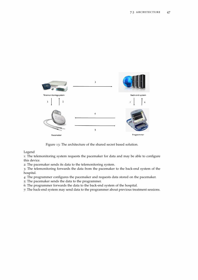
7.3 architecture 47
Figure 13: The architecture of the shared secret based solution.
Legend1: The telemonitoring system requests the pacemaker for data and may be able to configurethis device.2: The pacemaker sends its data to the telemonitoring system.3: The telemonitoring forwards the data from the pacemaker to the back-end system of thehospital.4: The programmer configures the pacemaker and requests data stored on the pacemaker.5: The pacemaker sends the data to the programmer.6: The programmer forwards the data to the back-end system of the hospital.7: The back-end system may send data to the programmer about previous treatment sessions.
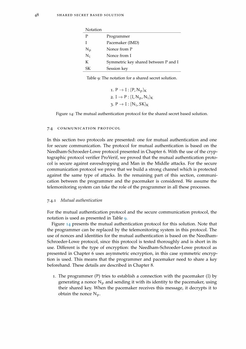
48 shared secret based solution
Notation
P Programmer
I Pacemaker (IMD)
Np Nonce from P
Ni Nonce from I
K Symmetric key shared between P and I
SK Session key
Table 9: The notation for a shared secret solution.
1. P → I : {P,Np}K
2. I→ P : {I,Np,Ni}K
3. P → I : {Ni,SK}K
Figure 14: The mutual authentication protocol for the shared secret based solution.
7.4 communication protocol
In this section two protocols are presented: one for mutual authentication and onefor secure communication. The protocol for mutual authentication is based on theNeedham-Schroeder-Lowe protocol presented in Chapter 6. With the use of the cryp-tographic protocol verifier ProVerif, we proved that the mutual authentication proto-col is secure against eavesdropping and Man in the Middle attacks. For the securecommunication protocol we prove that we build a strong channel which is protectedagainst the same type of attacks. In the remaining part of this section, communi-cation between the programmer and the pacemaker is considered. We assume thetelemonitoring system can take the role of the programmer in all these processes.
7.4.1 Mutual authentication
For the mutual authentication protocol and the secure communication protocol, thenotation is used as presented in Table 9.
Figure 14 presents the mutual authentication protocol for this solution. Note thatthe programmer can be replaced by the telemonitoring system in this protocol. Theuse of nonces and identities for the mutual authentication is based on the Needham-Schroeder-Lowe protocol, since this protocol is tested thoroughly and is short in itsuse. Different is the type of encryption: the Needham-Schroeder-Lowe protocol aspresented in Chapter 6 uses asymmetric encryption, in this case symmetric encryp-tion is used. This means that the programmer and pacemaker need to share a keybeforehand. These details are described in Chapter 8.
1. The programmer (P) tries to establish a connection with the pacemaker (I) bygenerating a nonce Np and sending it with its identity to the pacemaker, usingtheir shared key. When the pacemaker receives this message, it decrypts it toobtain the nonce Np.
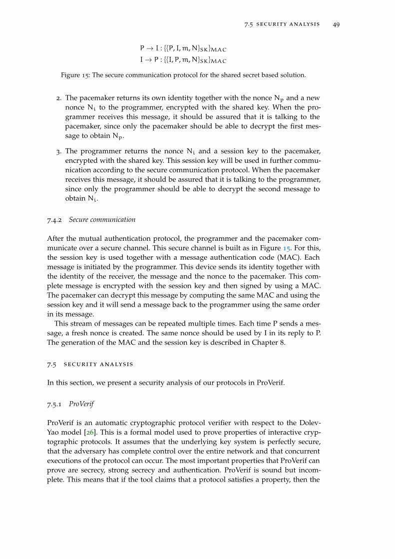
7.5 security analysis 49
P → I : {{P, I,m,N}SK}MAC
I→ P : {{I,P,m,N}SK}MAC
Figure 15: The secure communication protocol for the shared secret based solution.
2. The pacemaker returns its own identity together with the nonce Np and a newnonce Ni to the programmer, encrypted with the shared key. When the pro-grammer receives this message, it should be assured that it is talking to thepacemaker, since only the pacemaker should be able to decrypt the first mes-sage to obtain Np.
3. The programmer returns the nonce Ni and a session key to the pacemaker,encrypted with the shared key. This session key will be used in further commu-nication according to the secure communication protocol. When the pacemakerreceives this message, it should be assured that it is talking to the programmer,since only the programmer should be able to decrypt the second message toobtain Ni.
7.4.2 Secure communication
After the mutual authentication protocol, the programmer and the pacemaker com-municate over a secure channel. This secure channel is built as in Figure 15. For this,the session key is used together with a message authentication code (MAC). Eachmessage is initiated by the programmer. This device sends its identity together withthe identity of the receiver, the message and the nonce to the pacemaker. This com-plete message is encrypted with the session key and then signed by using a MAC.The pacemaker can decrypt this message by computing the same MAC and using thesession key and it will send a message back to the programmer using the same orderin its message.
This stream of messages can be repeated multiple times. Each time P sends a mes-sage, a fresh nonce is created. The same nonce should be used by I in its reply to P.The generation of the MAC and the session key is described in Chapter 8.
7.5 security analysis
In this section, we present a security analysis of our protocols in ProVerif.
7.5.1 ProVerif
ProVerif is an automatic cryptographic protocol verifier with respect to the Dolev-Yao model [26]. This is a formal model used to prove properties of interactive cryp-tographic protocols. It assumes that the underlying key system is perfectly secure,that the adversary has complete control over the entire network and that concurrentexecutions of the protocol can occur. The most important properties that ProVerif canprove are secrecy, strong secrecy and authentication. ProVerif is sound but incom-plete. This means that if the tool claims that a protocol satisfies a property, then the
50 shared secret based solution
property is satisfied. When the tool cannot prove a property, it tries to reconstruct anattack. This is an execution trace of the protocol that falsifies the desired property. Itcan give false attacks in this case, but then it is not able to prove the property.
The base of ProVerif lies in pi-calculus [1]. This is a process calculus which can dealwith processes that communicate and can consider the execution of several processesin parallel. It is primitive in the sense that it does not contain primitives as numbers,booleans or functions. The notion of name is important in pi-calculus. A name canbe a communication channel and a variable. There are various constructs of the pi-calculus: interaction, composition, restriction, replication, match and nil. Because ofthe basic structure of pi-calculus, it is easy to extend this calculus. One of theseextensions is spi-calculus, designed to represent cryptographic protocols. It providesa setting to analyse security protocols. It is possible to express security guarantees asequivalences between spi calculus processes. This is achieved by the introduction ofencryption and decryption constructs. ProVerif is a command-line tool which acceptsthe language pi-calculus and therefore also the spi-calculus.
7.5.2 Protocol verification
Now the security analysis is presented.
Protocol
For the analysis, only the protocol for mutual authentication as in Figure 14 is con-sidered. For this protocol, two tests are done: one for mutual authentication and onefor secrecy of the session key. The security of the secure channel is not tested withProVerif, since this depends on the security of the mutual authentication protocol.If the session key is not revealed during the mutual authentication protocol, a se-cure channel can be built with the session key and the MAC as presented in Figure15. No eavesdropping can happen and no MITM attack either, because of the formof encryption. Especially replay attacks cannot take place, because of the use of afresh nonce in every request from the programmer to the pacemaker. This protocolis tested in ProVerif on mutual authentication and secrecy of the session key sent inthe third message. For the syntax of ProVerif, we refer to the manual [26]. As a basis,we defined both protocols in ProVerif according to the communication stream.
Specification
For both tests on mutual authentication and secrecy, we implement the mutual au-thentication protocol as a basis. We define a free channel, the entities P and I (forthe programmer and the pacemaker) and two functions for symmetric encryptionand symmetric decryption. The session key is defined as a secret and has the label’private’. Details can be found in Appendix A in Listings 1 and 2. The processes for Pand I are defined by the messages that are coming in and the messages that are sentout. Furthermore, the processes contain the encryption and decryption functions forcomposing and decrypting messages. These processes are executed multiple times inparallel by the statement ((!P) | (!I)) to see if multiple sessions reveal some informa-tion during the mutual authentication phase. More details on the syntax of ProVerifcan be found in the manual [26].

7.5 security analysis 51
Properties
For secrecy, we only need to test on "query attacker: secret" to see if the attacker canretrieve the secret, which is the session key in this case, through the protocol. Fur-thermore, we explicitly state that we do not need to test on leakage of the symmetrickey.
For mutual authentication, we test on one to one correspondence. This tests if anevent M is always preceded by an event N and if every trace contains at least asmany N-events as M-events. This is tested for specific lines in the protocol by placingit between a begin and an end statement. For the mutual authentication protocol, thefollowing should be tested:
1. P → I : {P,Np}K
I: begin(I,P,Np)
2. I→ P : {I,Np,Ni}K
P: end(I,P,Np)
P: begin(P,I,Ni)
3. P → I : {Ni,SK}KI: end(P,I,Ni)
Now we test if each event in which the programmer receives nonce Np from thepacemaker is really preceded by an action from the pacemaker where it sends thenonce Np. The same is done for nonce Ni. By begin(P,I,Ni) and end(P,I,Ni) is checkedif receiving Ni implies that Ni is really sent by P. This property is the same as themathematical definition of injectivity. Now we can test mutual authentication, byspecifying the following queries in ProVerif:
query evinj: end(x,y,z) ==> evinj:begin(x,y,z)query evinj: end2(x,y,z) ==> evinj:begin2(x,y,z)
The first query tests authentication from I to P and the second query tests authen-tication from P to I. ProVerif explicitly tests if an attacker cannot mess with differentsessions to reveal information about the encrypted data.
Results
In Appendix A, Listing 1 presents the input for testing for mutual authentication inProVerif. In Listing 2, the output for ProVerif is given. We see that authentication forboth parties is satisfied, since the result for both queries is true. This means that afterthe execution of the mutual authentication protocol, both parties can be sure that theyare communicating with the entity they think they communicate with. For testing onsecrecy, the session key that is sent from the programmer to the pacemaker in thethird message is considered. Appendix A contains the input for ProVerif in Listing 3.Listing 4 presents the output from ProVerif and shows that the property is satisfiedfor this protocol, since ProVerif outputs true for the related query.
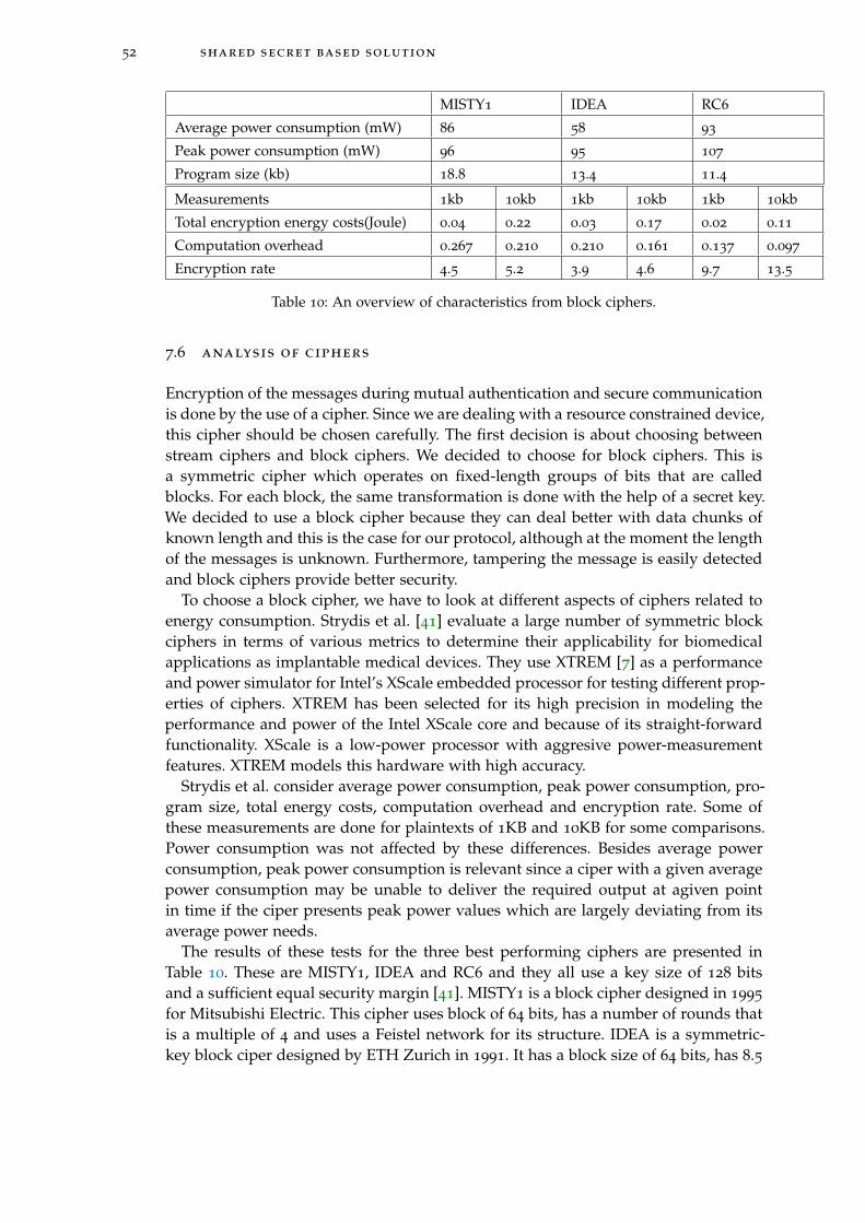
52 shared secret based solution
MISTY1 IDEA RC6
Average power consumption (mW) 86 58 93
Peak power consumption (mW) 96 95 107
Program size (kb) 18.8 13.4 11.4
Measurements 1kb 10kb 1kb 10kb 1kb 10kb
Total encryption energy costs(Joule) 0.04 0.22 0.03 0.17 0.02 0.11
Computation overhead 0.267 0.210 0.210 0.161 0.137 0.097
Encryption rate 4.5 5.2 3.9 4.6 9.7 13.5
Table 10: An overview of characteristics from block ciphers.
7.6 analysis of ciphers
Encryption of the messages during mutual authentication and secure communicationis done by the use of a cipher. Since we are dealing with a resource constrained device,this cipher should be chosen carefully. The first decision is about choosing betweenstream ciphers and block ciphers. We decided to choose for block ciphers. This isa symmetric cipher which operates on fixed-length groups of bits that are calledblocks. For each block, the same transformation is done with the help of a secret key.We decided to use a block cipher because they can deal better with data chunks ofknown length and this is the case for our protocol, although at the moment the lengthof the messages is unknown. Furthermore, tampering the message is easily detectedand block ciphers provide better security.
To choose a block cipher, we have to look at different aspects of ciphers related toenergy consumption. Strydis et al. [41] evaluate a large number of symmetric blockciphers in terms of various metrics to determine their applicability for biomedicalapplications as implantable medical devices. They use XTREM [7] as a performanceand power simulator for Intel’s XScale embedded processor for testing different prop-erties of ciphers. XTREM has been selected for its high precision in modeling theperformance and power of the Intel XScale core and because of its straight-forwardfunctionality. XScale is a low-power processor with aggresive power-measurementfeatures. XTREM models this hardware with high accuracy.
Strydis et al. consider average power consumption, peak power consumption, pro-gram size, total energy costs, computation overhead and encryption rate. Some ofthese measurements are done for plaintexts of 1KB and 10KB for some comparisons.Power consumption was not affected by these differences. Besides average powerconsumption, peak power consumption is relevant since a ciper with a given averagepower consumption may be unable to deliver the required output at agiven pointin time if the ciper presents peak power values which are largely deviating from itsaverage power needs.
The results of these tests for the three best performing ciphers are presented inTable 10. These are MISTY1, IDEA and RC6 and they all use a key size of 128 bitsand a sufficient equal security margin [41]. MISTY1 is a block cipher designed in 1995
for Mitsubishi Electric. This cipher uses block of 64 bits, has a number of rounds thatis a multiple of 4 and uses a Feistel network for its structure. IDEA is a symmetric-key block ciper designed by ETH Zurich in 1991. It has a block size of 64 bits, has 8.5
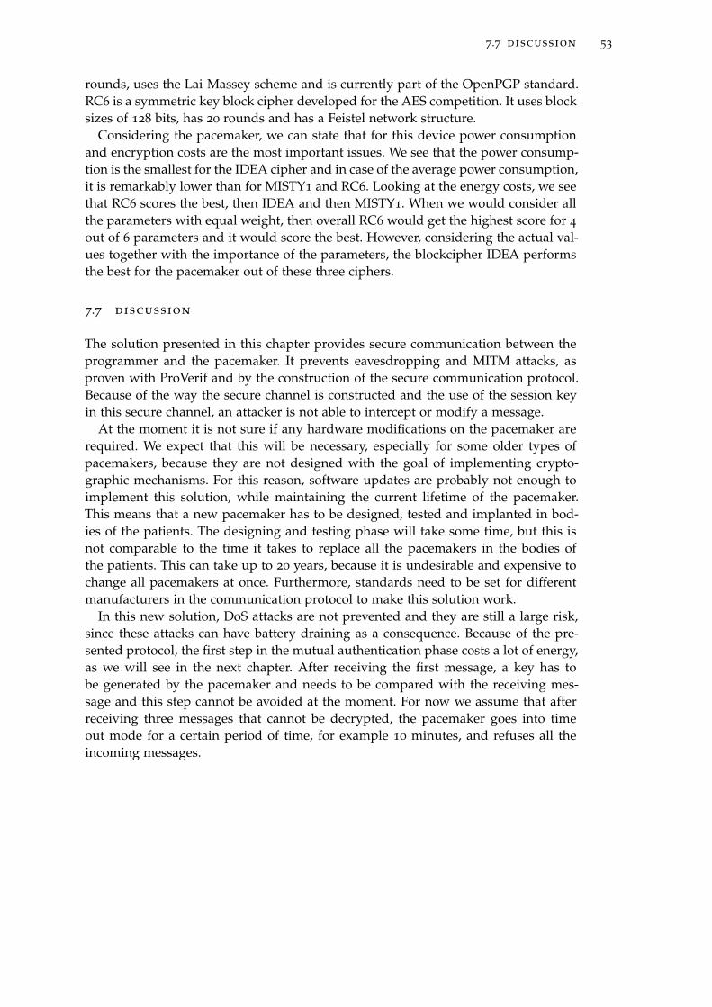
7.7 discussion 53
rounds, uses the Lai-Massey scheme and is currently part of the OpenPGP standard.RC6 is a symmetric key block cipher developed for the AES competition. It uses blocksizes of 128 bits, has 20 rounds and has a Feistel network structure.
Considering the pacemaker, we can state that for this device power consumptionand encryption costs are the most important issues. We see that the power consump-tion is the smallest for the IDEA cipher and in case of the average power consumption,it is remarkably lower than for MISTY1 and RC6. Looking at the energy costs, we seethat RC6 scores the best, then IDEA and then MISTY1. When we would consider allthe parameters with equal weight, then overall RC6 would get the highest score for 4
out of 6 parameters and it would score the best. However, considering the actual val-ues together with the importance of the parameters, the blockcipher IDEA performsthe best for the pacemaker out of these three ciphers.
7.7 discussion
The solution presented in this chapter provides secure communication between theprogrammer and the pacemaker. It prevents eavesdropping and MITM attacks, asproven with ProVerif and by the construction of the secure communication protocol.Because of the way the secure channel is constructed and the use of the session keyin this secure channel, an attacker is not able to intercept or modify a message.
At the moment it is not sure if any hardware modifications on the pacemaker arerequired. We expect that this will be necessary, especially for some older types ofpacemakers, because they are not designed with the goal of implementing crypto-graphic mechanisms. For this reason, software updates are probably not enough toimplement this solution, while maintaining the current lifetime of the pacemaker.This means that a new pacemaker has to be designed, tested and implanted in bod-ies of the patients. The designing and testing phase will take some time, but this isnot comparable to the time it takes to replace all the pacemakers in the bodies ofthe patients. This can take up to 20 years, because it is undesirable and expensive tochange all pacemakers at once. Furthermore, standards need to be set for differentmanufacturers in the communication protocol to make this solution work.
In this new solution, DoS attacks are not prevented and they are still a large risk,since these attacks can have battery draining as a consequence. Because of the pre-sented protocol, the first step in the mutual authentication phase costs a lot of energy,as we will see in the next chapter. After receiving the first message, a key has tobe generated by the pacemaker and needs to be compared with the receiving mes-sage and this step cannot be avoided at the moment. For now we assume that afterreceiving three messages that cannot be decrypted, the pacemaker goes into timeout mode for a certain period of time, for example 10 minutes, and refuses all theincoming messages.


8K E Y M A N A G E M E N T
This chapter describes the key management we developed for the solutions presentedin Chapter 6 and Chapter 7. This is done by using the key management lifecycle pre-sented by Posea [33], which is drawn in Figure 16. The following stages are importantin this process: (1) key generation, (2) key storage, (3) key distribution, (4) key usage,(5) key change and (6) key expiration, archival and destruction. For both solutions,each of these stages is discussed. The main focus is on the key generation stage ofthe shared secret based solution, since we developed a new way to generate dynamicsymmetric keys for medical devices.
8.1 proxy-based solution
In our architecture, the programmer, the telemonitoring system and the proxy need apublic-private key pair to enable secure communication between them. In this section,the key management for the proxy-based solution is presented according to the sixstages.
Key generation
Since the Needham-Schroeder-Lowe protocol suggests RSA keys for asymmetric en-cryption, we decided to use them in this system. During the first treatment, the pro-grammer generates three asymmetric key pairs: one key pair for the programmer, onefor the telemonitoring system and one for the proxy. This is done by using the Diffie-Hellman Key Agreement Method presented in a related RFC [37]. Details about thismethod can be found in this RFC.
Key storage
The key storage process is presented in Figure 17. The telemonitoring system andthe programmer are connected to the back-end system. For this reason, the proxy isdrawn seperated from the other devices. After generating the three key pairs in (1)for the programmer, the telemonitoring system and the proxy, the programmer sendsthese key pairs to other devices in (2). The key pair for the proxy is sent to the proxyand the public key for the proxy is also sent to the back-end system. For the proxy,the key is saved in a hardware security module (HSM). This compouting componentmanages digital keys for authentication. In (2), the programmer also sends the keypairs for the telemonitoring system and the programmer to the back-end system ofthe hospital. Furthermore, the programmer sends the public key from the program-mer and the telemonitoring system to the proxy. This happens in plaintext, sincethese keys are public and can be read by everyone. When these key pairs are sent,the programmer removes all the created pairs in (3).
55
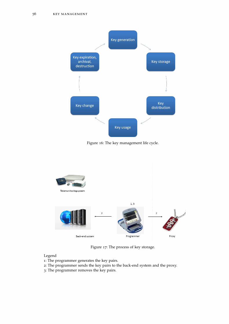
56 key management
Figure 16: The key management life cycle.
Figure 17: The process of key storage.
Legend1: The programmer generates the key pairs.2: The programmer sends the key pairs to the back-end system and the proxy.3: The programmer removes the key pairs.

8.1 proxy-based solution 57
Key distribution
Since for each patient, the devices that are involved in secure communication arethe programmer, the telemonitoring system and the proxy, the doctor is able to dothe key distribution manually. There is no reason to automate this process. This isdone by a pacemaker technician, since we assumed that we trust the medical staffin the hospital. For the distribution from the programmer to the proxy a distancebounding protocol is used as described before. The key for the telemonitoring canbe sent encrypted from the back-end system to the telemonitoring system over theInternet with a secure channel. The private key of the telemonitoring system onlyhas to be on the system during a monitoring session. At the start of this session, thetelemonitoring system can connect with the back-end system and temporarily get thekey. After the session, the telemonitoring system should erase the private key.
Key usage
To avoid key disclosure while the system is in use, it is good to perform all cryp-tographic operations in a physically isolated dedicated environment, offered by forexample an HSM. For this reason, we advise that the proxy, programmer and tele-monitoring system have such an HSM. Further research has to be done to determinewhat type of HSM fits in a proxy, since the proxy has size limits. But at least the pro-grammer and the telemonitoring system can contain such a module to perform allcryptographic operations during sessions with the pacemaker and prevent malwareto influence the encrypted communication.
Key change
In case a key is compromised or expired, a new key pair has to be generated. Fora programmer and a telemonitoring system, this can be done immediately by theprogrammer and keys can be directly transferred to the back-end system. But for thepacemaker, the patient has to come to the hospital where the programmer generatesa new key pair for his or her proxy. When the proxy is lost, stolen or broken, ithas to be replaced by a new one. In this case, the programmer destroys the old keypair and generate a new key pair. The process of key management of the keys isthen repeated. When a patient is treated in another hospital, it is considered as anemergency situation. The proxy is temporarily removed from the patient and there isno key exchange between the programmer and the proxy.
Key expiration, archival and destruction
The expiration date for the key pair is set to two years, according to the requirementsfrom NIST [3]. After this period of time, the whole key management cycle will berepeated. But first the expired key pair need to be destructed. There is no need toarchive them, since these expired keys will not play a role in further session anymore.

58 key management
Notation
K Secret
C Counter
X Time step in seconds
T0 Unix time to start counting time steps
Table 11: The notation for a Time-Based One-Time Password.
8.2 shared secret based solution
In this section, the key management for the shared secret based solution is presentedaccording to the six stages.
Key generation
In the proxy-based solution, the system uses static keys that are replaced every twoyears. The use of static keys is undesirable because of possible disclosure of thekeys. The use of dynamic keys is prefered and is the case in the shared secret basedsolution.
As a basis, the Diffie Hellman key agreement scheme is used between the program-mer and the pacemaker to establish a shared secret together. This secret is then partof the input to generate the dynamic symmetric key that is used by the programmer,pacemaker and telemonitoring system to communicate. This symmetric key is basedon the Time-Based One-Time Password (TOTP) [29]. This is a password that can beused only once and is based on a shared secret and the current time. The secret andthe timer are the input for a hash function, from which a key is generated. The TOTPis based on a HMAC-Based One-Time Password (HOTP) [28], which uses a counterinstead of a timer. The use of a counter is less secure and a timer is more practical forthis solution. For computing a TOTP, the notation in Table 11 is used.
The TOTP is computed according to the following equation:
TOTP = HOTP(K, T) = Truncate(HMAC− SHA1(K, T))
T and HMAC are defined as follows:
T =Current Unixtime− T0
X
HMAC(K, T) = H((K XOR opad)|H((K XOR ipad)|T)),
where opad and ipad stand for outer padding and inner padding. Both are one-block-long hexadecimal constants, where opad differs from ipad. The values do notinfluence the solution in a certain way, but are there to provide different inputs for thehash function. The hash function that is used in this HMAC is a Sha-1 hash. AlthoughSha-1 has a weakness with regards to collisions, this does not affect the security ofthe HMAC. HMAC resistance does not rely on resistance to collisions [28].
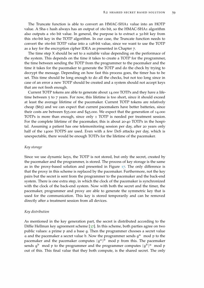
8.2 shared secret based solution 59
The Truncate function is able to convert an HMAC-SHA1 value into an HOTPvalue. A Sha-1 hash always has an output of 160 bit, so the HMAC-SHA1 algorithmalso outputs a 160 bit value. In general, the purpose is to extract a 32-bit key fromthis 160-bit key in the TOTP algorithm. In our case, the Truncate function needs toconvert the 160-bit TOTP value into a 128-bit value, since we want to use the TOTPas a key for the encryption cipher IDEA as presented in Chapter 7.
The time step X should be set to a suitable value depending on the performace ofthe system. This depends on the time it takes to create a TOTP for the programmer,the time between sending the TOTP from the programmer to the pacemaker and thetime it takes for the pacemaker to generate the TOTP and do the check by trying todecrypt the message. Depending on how fast this process goes, the timer has to beset. This time should be long enough to do all the checks, but not too long since incase of an error a new TOTP should be created and a system should not accept keysthat are not fresh enough.
Current TOTP tokens are able to generate about 14.000 TOTPs and they have a life-time between 5 to 7 years. For now, this lifetime is too short, since it should exceedat least the average lifetime of the pacemaker. Current TOTP tokens are relativelycheap ($65) and we can expect that current pacemakers have better batteries, sincetheir costs are between $35.000 and $45.000. We expect that the generation of 14.000
TOTPs is more than enough, since only 1 TOTP is needed per treatment session.For the complete lifetime of the pacemaker, this is about 20-40 TOTPs in the hospi-tal. Assuming a patient has one telemonitoring session per day, after 20 years onlyhalf of the 14000 TOTPS are used. Even with a few DoS attacks per day, which isunexpectable, there would be enough TOTPs for the lifetime of the pacemaker.
Key storage
Since we use dynamic keys, the TOTP is not stored, but only the secret, created bythe pacemaker and the programmer, is stored. The process of key storage is the sameas in the proxy-based solution and presented in Figure 17. The only difference isthat the proxy in this scheme is replaced by the pacemaker. Furthermore, not the keypairs but the secret is sent from the programmer to the pacemaker and the back-endsystem. There is one extra step, in which the clock of the pacemaker is synchronizedwith the clock of the back-end system. Now with both the secret and the timer, thepacemaker, programmer and proxy are able to generate the symmetric key that isused for the communication. This key is stored temporarily and can be removeddirectly after a treatment session from all devices.
Key distribution
As mentioned in the key generation part, the secret is distributed according to theDiffie Hellman key agreement scheme [37]. In this scheme, both parties agree on twopublic values: a prime p and a base g. Then the programmer chooses a secret valuea and the pacemaker a secret value b. Now the programmer sends ga mod p to thepacemaker and the pacemaker computes (ga)b mod p from this. The pacemakersends gb mod p to the programmer and the programmer computes (gb)a mod p
out of this. This final value that they both compute, is the shared secret. The only

60 key management
restriction is that the secret is 160 bits. This distribution of the secret can happen overan insecure channel, since both p and g are public.
The timer of the pacemaker can be synchronized with the back-end system duringthe first treatment.
Key usage
To avoid key disclosure while the system is in use, it is good to perform all crypto-graphic operations in a physically isolated dedicated environment. We propose thatthis is done by an HSM. So the pacemaker needs to contain a HSM or a compo-nent with similar capabilities. Furthermore, the programmer and the telemonitoringsystem needs such an HSM, as well.
Key change
In case of a disclosure of the secret, a new secret has to be generated between thepacemaker and the programmer. As a consequence, the patient has to visit the hos-pital for this process. In case of an emergency, a programmer from another hospitalmay synchronize with the pacemaker. The details of this process are explained inChapter 9. Then a new secret is established which works together with the correcttime from the back-end system of the hospital. This secret and time can be used as aone time key and are stored only during the session on the pacemaker or the back-end system, since it is unlikely that the patient will come back to this same hospitalfor more treatments. In this rare case, the key generation process can happen againby generating a new secret. The secret is valid for a short period of time which shouldbe long enough for the complete treatment.
Key expiration, archival and destruction
Secrets expire after 2 years of use. After this period, the pacemaker and program-mer need to establish a new secret with the Diffie Hellman key agreement scheme.The old secret can be destructed, when a new secret is generated. Secrets created inemergencies are removed from the pacemaker and the programmer directly after thetreatment, since they do not need to be stored for a longer period of time.
8.3 construction of the session key and the mac
For the secure channel of the shared secret based solution, a session key and a MACare necessary. These are created for every session the pacemaker establishes with aprogrammer or a telemonitoring system and are removed from the pacemaker at theend of each session. Computations with the session key are done in the HSM of thedevices. The session key is exchanged at the end of the protocol by the programmer.It is generated according to the key generation algorithm of the IDEA cipher, whichis not further explained here.
The MAC that is used for integrity of the messages during the secure commu-nication protocol is made by the use of a universal hash function. For this it uses
8.3 construction of the session key and the mac 61
the algorithm UMAC as propsed in RFC 4418 [24]. This is a very fast and relativelylightweight algorithm to generate MACs and possible to combine with various typeof block ciphers. It relies on addition of 32-bit and 64-numbers and multiplication of32-bit numbers. These operations are well-supported by contemporary machines. Theonly cryptographic component that is used, is the block cipher for generating pseu-dorandom pads and internal key material. We advise to use it in combination withthe IDEA cipher. The default block cipher is AES, but this block cipher is relativelymore heavy than IDEA.


9E M E R G E N C Y A C C E S S S O L U T I O N S
In this chapter, we present the emergency access approaches for the systems pre-sented in Chapter 6 and Chapter 7. For the proxy-based system, we present onesolution that fits all the requirements described in Chapter 6. This solution will al-ways work, because of the design of the system and the possibility to remove layers ofsecurity easily. For the shared secret based system presented in Chapter 7, we presentour new solution in Section 9.2, where the pacemaker functions as an emergency de-tector. Our work is the first in giving concrete parameters and a method of detectingemergencies. However, this solution has the limitation that not all emergency situa-tions can be recognized and covered. For this reason, some alternative solutions arepresented that can be used to authenticate to the system. They increase the successof accessing the pacemaker in case of an emergency.
9.1 emergency solution for the proxy-based system
During an emergency, a patient visits a hospital that is close by. Depending on his orher location, this can be A) the hospital he or she regularly visits or B) a hospital inanother city or even in another country where he or she has never been before. In caseA, the pacemaker can be accessed in the same way as during regular treatments andthe system is the same as in Figure 10. In case B, the proxy has to communicate with aprogrammer it does not know. Both the proxy and the programmer do not have eachothers public key. It takes time to exchange public keys in a safe way, which is notpreferred in an urgent situation. We remark that in case of an emergency, safety ofthe patient is more important than security of the communication. In this situation,the proxy is temporarily removed. The programmer and the pacemaker communi-cate as systems that are in use nowadays, without encryption of the communication.After the treatment, the proxy can be reattached to the body of the patient and thepacemaker is protected again.
The system architecture for this situation is presented in Figure 18, where only aprogrammer and a pacemaker are involved. The logs of the treatment are stored inthe hospital where the patient is treated. We assume that the patient should transferthe logs from this data to the hospital where he or she is regularly treated. In general,this information is not exchanged between the hospitals without help of the patient.Furthermore, during the next regular treatment, the cardiologist should check thelogs from the emergency that are stored in the pacemaker and check if the settingsof the pacemaker are correct.
9.2 emergency solution for the shared secret based system
In this section, we present a new solution for emergency access to the pacemakerwhere the pacemaker takes the role of an emergency detector. Since it is difficult toguarantee a detection system that covers 100% of the emergencies, the use of a second
63

64 emergency access solutions
Figure 18: The architecture in an emergency situation.
Legend1: The programmer configures the pacemaker and requests data stored on the pacemaker.2: The pacemaker sends the data to the programmer.
way to authenticate to the system might be needed. For this reason, some alternativesare presented as well.
9.2.1 The pacemaker as an emergency detector
In the shared secret based system presented in Chapter 7, security is not an additionallayer on a removable device as it is for the proxy-based system. As a consequence,there is no easy way to access the pacemaker in case of an emergency when a patientis not near to the hospital where he or she is regularly treated. This has to do with thefact that the elements that are necessary to generate keys are only stored on the pace-maker and the back-end system of the hospital where the patient is regularly treated.During an emergency, the pacemaker should be immediately accessible by a medicalstaff member in any part of the world. Although we want to prevent unauthorizedaccess to the pacemaker even in case of an emergency, safety of the patient goesabove all. No time can be lost by retrieving the correct key. In our system, we createthe possibility for a pacemaker to synchronize again with a programmer during anemergency by establishing a new secret and follow the process of key managementas described in Chapter 8.
The principle is that access control is based on the condition of the heart andthat the pacemaker can operate in two modes: a regular mode and an emergencymode. When the heart is in a condition where the pacemaker is able to support it,there is no immediate access needed by other parties. This is the regular mode andsecurity mechanisms are provided. In case the heart functions abnormally and thepacemaker is not able to correct this behavior, help by medical staff is needed. Nowthe pacemaker goes into emergency mode. This mode is explained in the remainder
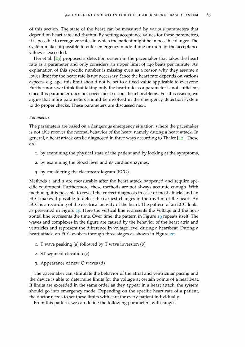
9.2 emergency solution for the shared secret based system 65
of this section. The state of the heart can be measured by various parameters thatdepend on heart rate and rhythm. By setting acceptance values for these parameters,it is possible to recognize states in which the patient might be in possible danger. Thesystem makes it possible to enter emergency mode if one or more of the acceptancevalues is exceeded.
Hei et al. [23] proposed a detection system in the pacemaker that takes the heartrate as a parameter and only considers an upper limit of 140 beats per minute. Anexplanation of this specific number is missing even as a reason why they assume alower limit for the heart rate is not necessary. Since the heart rate depends on variousaspects, e.g. age, this limit should not be set to a fixed value applicable to everyone.Furthermore, we think that taking only the heart rate as a parameter is not sufficient,since this parameter does not cover most serious heart problems. For this reason, weargue that more parameters should be involved in the emergency detection systemto do proper checks. These parameters are discussed next.
Parameters
The parameters are based on a dangerous emergency situation, where the pacemakeris not able recover the normal behavior of the heart, namely during a heart attack. Ingeneral, a heart attack can be diagnosed in three ways according to Thaler [42]. Theseare:
1. by examining the physical state of the patient and by looking at the symptoms,
2. by examining the blood level and its cardiac enzymes,
3. by considering the electrocardiogram (ECG).
Methods 1 and 2 are measurable after the heart attack happened and require spe-cific equipment. Furthermore, these methods are not always accurate enough. Withmethod 3, it is possible to reveal the correct diagnosis in case of most attacks and anECG makes it possible to detect the earliest changes in the rhythm of the heart. AnECG is a recording of the electrical activity of the heart. The pattern of an ECG looksas presented in Figure 19. Here the vertical line represents the Voltage and the hori-zontal line represents the time. Over time, the pattern in Figure 19 repeats itself. Thewaves and complexes in the figure are caused by the behavior of the heart atria andventricles and represent the difference in voltage level during a heartbeat. During aheart attack, an ECG evolves through three stages as shown in Figure 20:
1. T wave peaking (a) followed by T wave inversion (b)
2. ST segment elevation (c)
3. Appearance of new Q waves (d)
The pacemaker can stimulate the behavior of the atrial and ventricular pacing andthe device is able to determine limits for the voltage at certain points of a heartbeat.If limits are exceeded in the same order as they appear in a heart attack, the systemshould go into emergency mode. Depending on the specific heart rate of a patient,the doctor needs to set these limits with care for every patient individually.
From this pattern, we can define the following parameters with ranges.
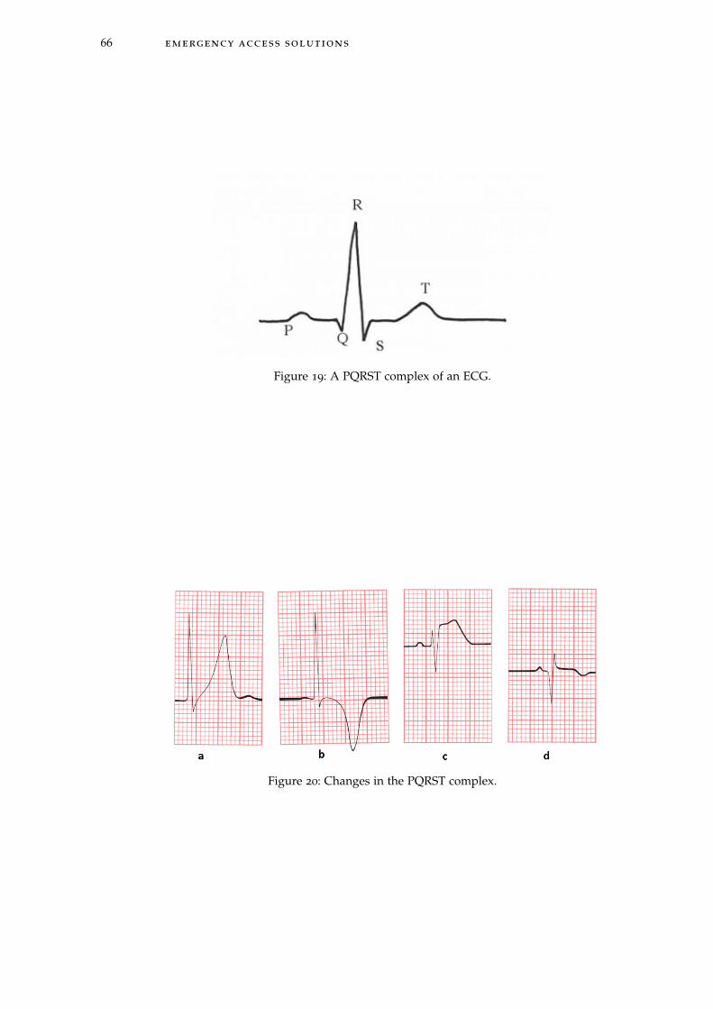
66 emergency access solutions
Figure 19: A PQRST complex of an ECG.
Figure 20: Changes in the PQRST complex.

9.2 emergency solution for the shared secret based system 67
• The height of the T wave. This parameter can have a positive Voltage value or anegative value. By defining an upper limit and a lower limit for the T wave, wecan check if this limit is exceeded. Both limits are determined by the doctor foreach patient, since it depends on the height of T waves in a regular condition. Itis reasonable that a certain percentage is set that the T wave is allowed to differfrom the regular situation.
• The ST segment elevation. As a consequence of a T wave peak and a T waveinversion, the ST segment will elevate. Now we can measure if it elevates com-pared to the previous heart beat. This parameter is a boolean with the valueTrue if ST segment elevation happens and False if it does not happen.
• A new Q wave. After ST segment elevation, a new Q wave can appear. Thisparameter is a boolean with value True if a new Q wave appears and False ifno new Q wave appears.
Another parameter that has to be measured, is the heart rate itself. An upper limitand lower limit should be set for this parameter, since in case of an extremely lowor extremely high heart rate a medical staff member should be able to access thepacemaker directly. This is done by the doctor for each patient seperately and isdetermined by considering a certain percentage that the heart rate may differ fromthe heart rate in a regular situation.
As shortly explained, the system enters an emergency mode when it discovers anemergency situation. To be more specific, the emergency mode is reached, when thefollowing logical formula gives "True" as an output:
emergency = heart rate > upper limit1 ∨ heart rate < lower limit1∨
(T wave > upper limit2 ∧ T wave < lower limit2
∧Appearance of ST segment elevation ∧ NewQwave)
This check can be done every minute for example to control the heart rate and torecognize patterns of a possible emergency situation.
Now that the parameters are defined, we can explain how the system functions inemergency mode with the help of a finite state diagram.
Finite state diagram
The finite state diagram related to these states is presented in Figure 21. As explainedbefore, there are two modes of the system: an emergency mode and a non-emergencymode. In the non-emergency mode, the pacemaker can only communicate with de-vices that are able to authenticate to the programmer. But when a pacemaker noticesan emergency, the system should go into emergency mode. In this mode, the pace-maker can synchronize with a programmer and establish a secure connection. Thestates related to the emergency mode are the following.
• Protected: in this state, the pacemaker is only accesible by authentication andthe communication is encrypted. It can only communicate with the program-mer that is meant for regular treatments.
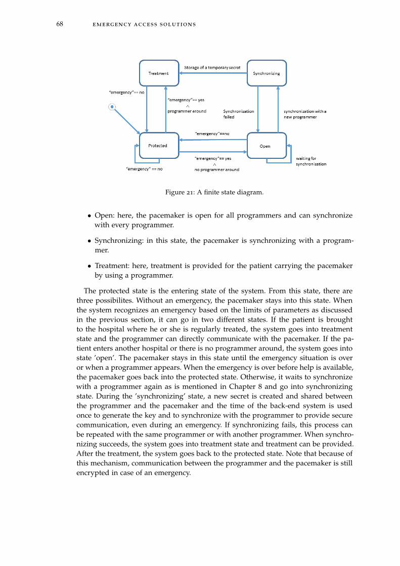
68 emergency access solutions
Figure 21: A finite state diagram.
• Open: here, the pacemaker is open for all programmers and can synchronizewith every programmer.
• Synchronizing: in this state, the pacemaker is synchronizing with a program-mer.
• Treatment: here, treatment is provided for the patient carrying the pacemakerby using a programmer.
The protected state is the entering state of the system. From this state, there arethree possibilites. Without an emergency, the pacemaker stays into this state. Whenthe system recognizes an emergency based on the limits of parameters as discussedin the previous section, it can go in two different states. If the patient is broughtto the hospital where he or she is regularly treated, the system goes into treatmentstate and the programmer can directly communicate with the pacemaker. If the pa-tient enters another hospital or there is no programmer around, the system goes intostate ’open’. The pacemaker stays in this state until the emergency situation is overor when a programmer appears. When the emergency is over before help is available,the pacemaker goes back into the protected state. Otherwise, it waits to synchronizewith a programmer again as is mentioned in Chapter 8 and go into synchronizingstate. During the ’synchronizing’ state, a new secret is created and shared betweenthe programmer and the pacemaker and the time of the back-end system is usedonce to generate the key and to synchronize with the programmer to provide securecommunication, even during an emergency. If synchronizing fails, this process canbe repeated with the same programmer or with another programmer. When synchro-nizing succeeds, the system goes into treatment state and treatment can be provided.After the treatment, the system goes back to the protected state. Note that because ofthis mechanism, communication between the programmer and the pacemaker is stillencrypted in case of an emergency.
9.2 emergency solution for the shared secret based system 69
False positives and negatives
It is important to minimize false positives and false negatives in this solution. Inthis system, false positives are situations in which the pacemaker goes in emergencymode, when there is no emergency. This can happen when the heart rate is high orlow or other parameters exceed a limit, but the patient is not experiencing a difficultsituation. Now resynchronization is possible in a situation where this is not necessary.In case an attacker is around, he or she is able to access and connect. The number offalse positives should be minimized by choosing the limits for the parameters verycarefully. During the occurence of a false negative, the patient is in an emergency,but the device does not recognize the emergency. Therefore, access is necessary, butthe pacemaker does not recognize an emergency mode. This can be the case whenthere is an emergency because of non-related heart problems. This is a problem, sincethe pacemaker has to be turned off during some surgeries. However, at the momentthere is no easy way to stop the pacemaker from functioning. And this is also a goodproperty, because it should not be easy for an attacker to turn of the pacemaker.
9.2.2 Alternatives
There are several possible emergency solutions that solve the problem of false posi-tives and false negatives, since it is not dependent on measurements, but on externalcomponents and systems. In all solutions there is a better way to secure that onlymedical staff members access the pacemaker in case of an emergency. However, itmight take too much time to access the pacemaker, since the medical staff is depend-ing on other parties or systems.
Smartcard
The first solution is that the patient carries a paper card or smartcard in his or herwallet with an access code to access the pacemaker in case of an emergency. Thesecards can be standardized and can be a replacement of cards that patients are carry-ing in their wallet with the type of the pacemaker and the manufacturer. In this case,access is guaranteed by sending the code on the smartcard from the programmer tothe pacemaker, but it is also possible that an attacker steals the wallet with the cardand gets access in the same way. Furthermore, the card has the property that it canbe lost, stolen or broken and that in case of an emergency, it is not available. In thiscase, access would not be possible. This is the main reason why an external object ordevice will never be an optimal emergency solution.
Alarm line
Another solution is the use of an alarm line system. Each country already has analarm line system, this service can be added to this system. This alarm line can haveaccess to a database with all the secrets and timers and will be able to generate theTOTP. The alarm line is unique for each country. In case of an emergency, the medicalstaff has to call to the alarm line of the country where the patient is from.
The process can happen for example as follows: The doctor calls the alarm numberby phone and the insurance company checks this caller id. If it appears in a database

70 emergency access solutions
with phone numbers from a hospital, it sends a key to access the pacemaker to thehospital by fax. By responding this call with a fax, we can be sure this key arrivesat the hospital. It does not make sense if an attacker spoofs the caller id, since he orshe will never receive the key from the fax. Now this key can be used to encrypt themessage from the programmer to the pacemaker to start authentication.
Positive aspects is the fact that there are multiple verifications by the caller idand the fax, to be sure it is a medical staff member and no attacker. Furthermore, itneeds a local database for each country at the alarm service. A negative aspect is thatthe solution may take a large amount of time. It takes time to call, to search in thedatabase and to pass the TOTP. Furthermore, since the TOTP is a 128-bit key, it isdifficult to give this by fax. Another possibility is to send it over the Internet, but thisrequires strong encryption of the data sent.
Global key management system
The ideal solution to retrieve emergency access only for authorized entities and forother problems (e.g. an electronic patient health record) would be an electronic globalkey management system. When all hospitals worldwide have access to this globalsystem, it is possible to define who has access at what moments. With such a system,it would be easy to ask for keys in any part of the world, at each hospital that isconnected to the database. By looking for the identity of the patient, the secret andthe timer could be immediately retrieved and the key could be determined. This canbe done in a few seconds and would only depend on the availability of the database.There are not that many disadvantages to this solution, the only thing is that at thispoint in time, it is not realistic to have such a database. It is already hard enoughto have a national patient health record system, a global database would be muchharder, because standards related to database systems, but also access control rightsneed to be set worldwide.
10C O N C L U S I O N S & F U T U R E W O R K
In this chapter, we present the conclusions of the work performed for this thesis. Fur-thermore we discuss possible directions for future work related to implementationdetails of the solution and emergency access solutions.
10.1 conclusion
In this thesis, we tried and answered the research question "How can we define a systemthat provides confidentiality and integrity of sensitive information during the communicationbetween a pacemaker and a legitimate programmer, while ensuring availability of informationin case of an emergency?". The goal is to find an optimal system that fulfils the require-ments and see what possible emergency access solutions are applicable. This researchquestion is split up in two subquestions namely:
1. What system can provide confidentiality and integrity of sensitive information duringcommunication between a pacemaker and a legitimate programmer?
2. How can emergency access be assured in this system?
To answer the first subquestion, we had the following approach. We defined a listof requirements for an optimal solution. Considering these requirements, it was im-mediately clear that it was hard to meet different requirements at the same time. Thelargest challenge was the fact that certain properties could not be assured withouthaving knowledge about the exact components that were in the pacemaker. Sincepacemakers are property of the manufacturers and they are each others competitors,manufacturers were not willing to give details about the architecture and communi-cation protocols of the devices. This led to the decision to come up with two differenttypes of solutions: one that is directly applicable on the current pacemaker and sec-ond that may require changes in the pacemaker design, but fits more requirements.
The solution that is directly applicable, is a proxy-based solution based on TheShield [17]. From the list of requirements we formulated for this solution, we de-cided to use the Needham-Schroeder-Lowe protocol to guarantee secure communi-cation between the programmer, proxy and pacemaker. Although most requirementsare met, the use of a proxy as a solution is considered as not to be a desirable solu-tion. Since the external device can be lost, stolen or broken, the additional securitylayer is not always guaranteed. For this reason, a shared secret based solution is pre-sented without a proxy. For this solution, we defined a list of requirements and wedesigned a mutual authentication protocol and a secure channel. This communica-tion protocol is based on a combination of the lightweight block cipher IDEA andthe use of Time-Based One-Time Passwords (TOTP) as an encryption key. This keymanagement method related to the TOTP is a new way to make use of a dynamickey solution instead of the use of static keys which is frequently suggested.
The second subquestion is answered by presenting a new system in which thepacemaker behaves as an emergency detector. Our system constantly measures var-
71
72 conclusions & future work
ious parameters of the heart and when one or more of these parameters exceed alimit, the pacemaker goes into emergency mode. In this mode, the pacemaker is ableto synchronize again with another programmer. This type of solution avoids the useof a central key management scheme or an external wearable object that the patientneeds to carry to access the pacemaker in case of an emergency. Our work is the firstin giving concrete parameters and a method of detecting emergencies.
10.2 future work
This work addresses future research in two main areas: the implementation detailsof the solution and a specification of the emergency access solution.
10.2.1 Implementation details
To implement the solution presented in Chapter 7, the current architecture of thepacemaker needs to be studied carefully. Research has to be done to investigate ifthe necessary components are available and what will be the effect of the securitymechanisms on the performance and the lifetime of the device. The needed type andcapacity of the battery has to be determined together with the type of processor andother relevant components. With these estimations a prototype needs to be build tomeasure the performance. In this research, it was not possible to make a start on thispart, since manufacturers were not willing to participate. Since at the moment hardlyany security mechanisms are implemented in medical devices we advise manufac-turers to work together with researchers who studied security aspects to guaranteethe security properties of medical devices in the future. Furthermore, standardisingparts of the communication process and the capabilities of the components of IMDswould make it more easy to address security related difficulties. Organizations thatdefine standards in this area could play an important role here.
10.2.2 Emergency access
For the emergency access solution, where the pacemaker plays the role of an emer-gency detector, it is important to develop a way to determine the limits of the pa-rameters in the emergency detection system. Here, the number of false positives andfalse negatives should be as small as possible. To complete this solution, it shouldbe determined how to respond in case of a false negative. In our presented solution,this is an open problem. An option is to introduce a second backdoor in the systemto cover most false positives, but it is hard to cover 100% of the cases.

B I B L I O G R A P H Y
[1] M. Abadi and A. D. Gordon. A calculus for cryptographic protocols: The spicalculus. December 1996.
[2] D. Abraham, G. Dolan, G. Double, and J. Stevens. Transaction security system.IBM Systems Journal, 30(2):206–229, 1991.
[3] E. Barker, W. Barker, W. Burr, W. Polk, and M. Smid. Recommendation for keymanagement - part 1: General. NIST Special Publication 800-57, 2007.
[4] C. Beck, D. Masny, W. Geiselmann, and G. Bretthauer. Block cipher based secu-rity for severely resource-constrained implantable medical devices. In ISABEL’11 Proceedings of the 4th International Symposium on Applied Sciences in Biomedicaland Communication Technologies, October 2011.
[5] S. Brands and D. Chaum. Distance-bounding protocols (extended abstract). InEUROCRYPT93, Lecture Notes in Computer Science 765, pages 344–359. Springer-Verlag, 1993.
[6] W. Burleson, S. S. Clark, B. Ransford, and K. Fu. Design challenges for secureimplantable medical devices. In DAC ’12 Proceedings of the 49th Annual DesignAutomation Conference, pages 12–17, June 2012.
[7] G. Contreras, M. Martonosi, J. Peng, R. Ju, and G. Lueh. Xtrem: A power simu-lator for the intel xscale core. LCTES’04, pages 115–125, 2004.
[8] Council Directive. 90/395/eec. Official Journal of the European Communities, June1990.
[9] T. Denning, A. Borning, B. Friedman, B. T. Gill, T. Kohno, and W. Maisel. Pa-tients, pacemakers, and implantable defibrillators: Human values and securityfor wireless implantable medical devices. In CHI ’10, Proceedings of the SIGCHIConference on Human Factors in Computing Systems, pages 917–926, 2010.
[10] T. Denning, K. Fu, and T. Kohno. Absence makes the heart grow fonder: Newdirections for implantable medical device security. In HOTSEC’08 Proceedings ofthe 3rd conference on Hot topics in security, 2008.
[11] EBAY. Pacemaker programmer, http://www.ebay.com/bhp/pacemaker-programmer, March 2014.
[12] N. Ellouze, M. Allouche, H. B. Ahmed, S. Rekhis, and N. Boudriga. Securingimplantable cardiac medical devices: Use of radio frequency energy harvesting.In TrustED ’13 Proceedings of the 3rd international workshop on Trustworthy embeddeddevices, pages 35–42, November 2013.
[13] N. Ellouze, M. Allouche, H. B. Ahmed, S. Rekhis, and N. Boudriga. Security ofimplantable medical devices: limits, requirements, and proposals. Security andCommunication Networks Journal, November 2013.
73

74 bibliography
[14] Ettus Research. Usrp products, https://www.ettus.com/product, March 2014.
[15] Federal Communications Commission. Mics medical implant communicationservices. FCC 47CFR95.601-95.673 Subpart E/I Rules for MedRadio Services, 2013.
[16] A. Ferreira, R. Cruz-Correia, L. Antunes, P. Farinha, E. Oliveira-Palhares, D. W.Chadwick, and A. Costa-Pereira. How to break access control in a controlledmanner. In CBMS ’06 Proceedings of the 19th IEEE Symposium on Computer-BasedMedical Systems, pages 847–854, 2006.
[17] S. Gollakota, H. Hassanieh, B. Ransford, D. Katabi, and K. Fu. They can hearyour heartbeats: Non-invasive security for implantable medical devices. In SIG-COMM ’11 Proceedings of the ACM SIGCOMM 2011 conference, pages 2–13, 2011.
[18] Government Accountability Office. Medical Devices: FDA Should Expand Its Con-sideration of Information Security for Certain Types of Devices, August 2012.
[19] S. A. P. Haddad, R. P. M. Houen, and W. A. Serdijn. The evolution of pacemakers.Engineering in Medicine and Biology Magazine, IEEE, 25(3), May/June 2006.
[20] D. Halperin, T. Heydt-Benjamin, B. Ransford, and S. Clark. Pacemakers and im-plantable cardiac defibrillators: Software radio attacks and zero-power defenses.In Security and Privacy (SP), 2008 IEEE Symposium, pages 129–142, May 2008.
[21] Heart Rhythm Society. Pacemakers, http://www.hrsonline.org/patient-resources/patient-information-sheets#axzz2wwarxdxr, March 2014.
[22] X. Hei and X. Du. Biometric-based two-level secure access control for im-plantable medical devices during emergencies. In INFOCOM, 2011 ProceedingsIEEE, pages 346 –350, April 2011.
[23] X. Hei, X. Du, J. Wu, and F. Hu. Defending resource depletion attacks on im-plantable medical devices. Global Telecommunications Conference, pages 1–5, De-cember 2010.
[24] T. Krovetz. Umac: Message authentication code using universal hashing. RFC4418, March 2006.
[25] U. Lakshmanadoss, A. Shah, and J. J. Daubert. Telemonitoring of the pacemaker.In Modern Pacemakers - Present and Future. InTech, Rijeka, 2011.
[26] B. Lanchet, B. Smyth, and V. Cheval. Proverif 1.88pl1: Automatic cryptographicprotocol verifier. June 2014.
[27] G. Lowe. An attack on the needham-schroeder public key authentication proto-col. Information Processing Letters, 56(3):131–136, November 1995.
[28] D. M’Raihi, M. Bellare, F. Hoornaert, D. Naccache, and O. Ranen. Hotp: Anhmac-based one-time password algorithm. RFC 4226, December 2005.
[29] D. M’Raihi, S. Machani, M. Pei, and J. Rydell. Totp: Time-based one-time pass-word algorithm. RFC 6238, May 2011.

bibliography 75
[30] OWASP Attacks. https://www.owasp.org/index.php/category:attack. April2014.
[31] OWASP Threat Agent. https://www.owasp.org/index.php/category:threat_agent.April 2014.
[32] OWASP Vulnerability. https://www.owasp.org/index.php/category:vulnerability.April 2014.
[33] S. Posea. Renewal Periods for Cryptographic Keys. 2012.
[34] V. Pournaghshband, M. Sarrafzadeh, and P. Reiher. Securing legacy mobile med-ical devices. MobiHealth, 2012.
[35] R. Needham and M. Schroeder. Using encryption for authentication in largenetworks of computers. Communications of the ACM, 21(12):993–999, December1978.
[36] K. B. Rasmussen, C. Castelluccia, T. Heydt-Benjamin, and S. Capkun. Proximity-based access control for implantable medical devices. In CSS ’09 Proceedings ofthe 16th ACM conference on Computer and communications security, pages 410–419,November 2009.
[37] E. Rescorla. Diffie-hellman key agreement method. RFC 2631, June 1999.
[38] M. Rostami, W. Burleson, and F. K. A. Juels. Balancing security and util-ity in medical devices? In Design Automation Conference (DAC), 2013 50thACM/EDAC/IEEE, pages 1–6, May 2013.
[39] M. Rostami, A. Juels, and F. Koushanfar. Heart-to-heart (h2h): Authenticationfor implanted medical devices. In CCS ’13 Proceedings of the 2013 ACM SIGSACconference on Computer & communications security, pages 1099–1112, November2013.
[40] C. Strydis, R. M. Seepers, P. Peris-Lopez, D. Siskos, and I. Sourdis. A systemarchitecture, processor, and communication protocol for secure implants. ACMTransactions on Architecture and Code Optimization, 10(4), December 2013.
[41] C. Strydis, D. Zhu, and G.N.Gaydadjiev. Profiling of symmetric-encryption algo-rithms for a novel biomedical-implant architecture. 5th Conference on CumputingFrontiers, pages 231–240, May 2008.
[42] M. S. Thaler. The Only EKG book you’ll ever need. Lippincott Williams & Wilkins,2007.
[43] F. Xu, Z. Qin, C. C. Tan, B. Wang, and Q. Li. Imdguard: Securing implantablemedical devices with the external wearable guardian. In INFOCOM, 2011 Pro-ceedings IEEE, pages 1862–1870, April 2011.
[44] M. Zhang, A. Raghunathan, and N. K. Jha. Medmon: Securing medical de-vices through wireless monitoring and anomaly detection. IEEE Transactions onBiomedical Ciruits and Systems, 7(6):871–881, December 2013.

76 bibliography
[45] M. Zhang, A. Raghunathan, and N. K. Jha. Towards trustworthy medical devicesand body area networks. In Design Automation Conference (DAC), 2013 50th ACM/ EDAC / IEEE, pages 1–6, May 2013.
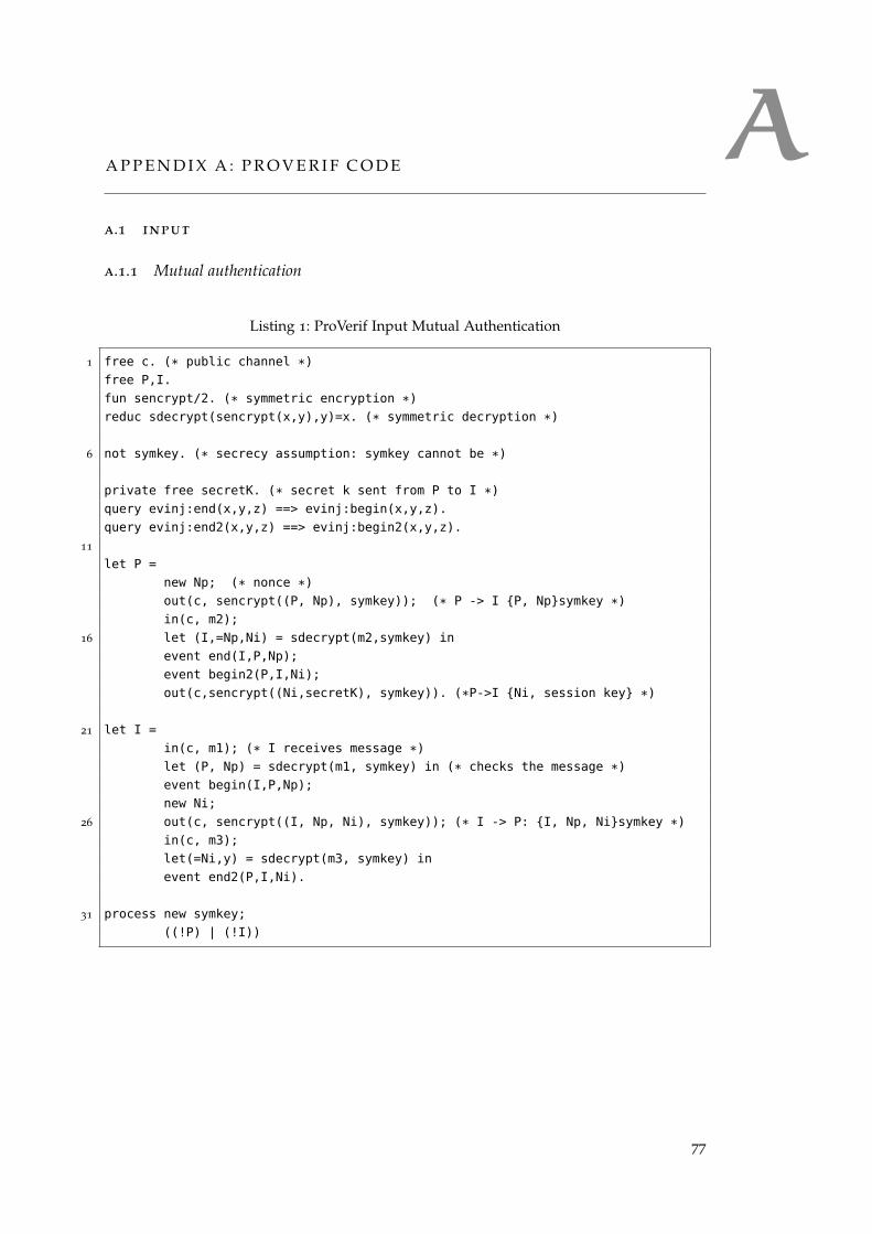
AA P P E N D I X A : P R O V E R I F C O D E
a.1 input
a.1.1 Mutual authentication
Listing 1: ProVerif Input Mutual Authentication
1 free c. (* public channel *)
free P,I.
fun sencrypt/2. (* symmetric encryption *)
reduc sdecrypt(sencrypt(x,y),y)=x. (* symmetric decryption *)
6 not symkey. (* secrecy assumption: symkey cannot be *)
private free secretK. (* secret k sent from P to I *)
query evinj:end(x,y,z) ==> evinj:begin(x,y,z).
query evinj:end2(x,y,z) ==> evinj:begin2(x,y,z).
11
let P =
new Np; (* nonce *)
out(c, sencrypt((P, Np), symkey)); (* P -> I {P, Np}symkey *)
in(c, m2);
16 let (I,=Np,Ni) = sdecrypt(m2,symkey) in
event end(I,P,Np);
event begin2(P,I,Ni);
out(c,sencrypt((Ni,secretK), symkey)). (*P->I {Ni, session key} *)
21 let I =
in(c, m1); (* I receives message *)
let (P, Np) = sdecrypt(m1, symkey) in (* checks the message *)
event begin(I,P,Np);
new Ni;
26 out(c, sencrypt((I, Np, Ni), symkey)); (* I -> P: {I, Np, Ni}symkey *)
in(c, m3);
let(=Ni,y) = sdecrypt(m3, symkey) in
event end2(P,I,Ni).
31 process new symkey;
((!P) | (!I))
77
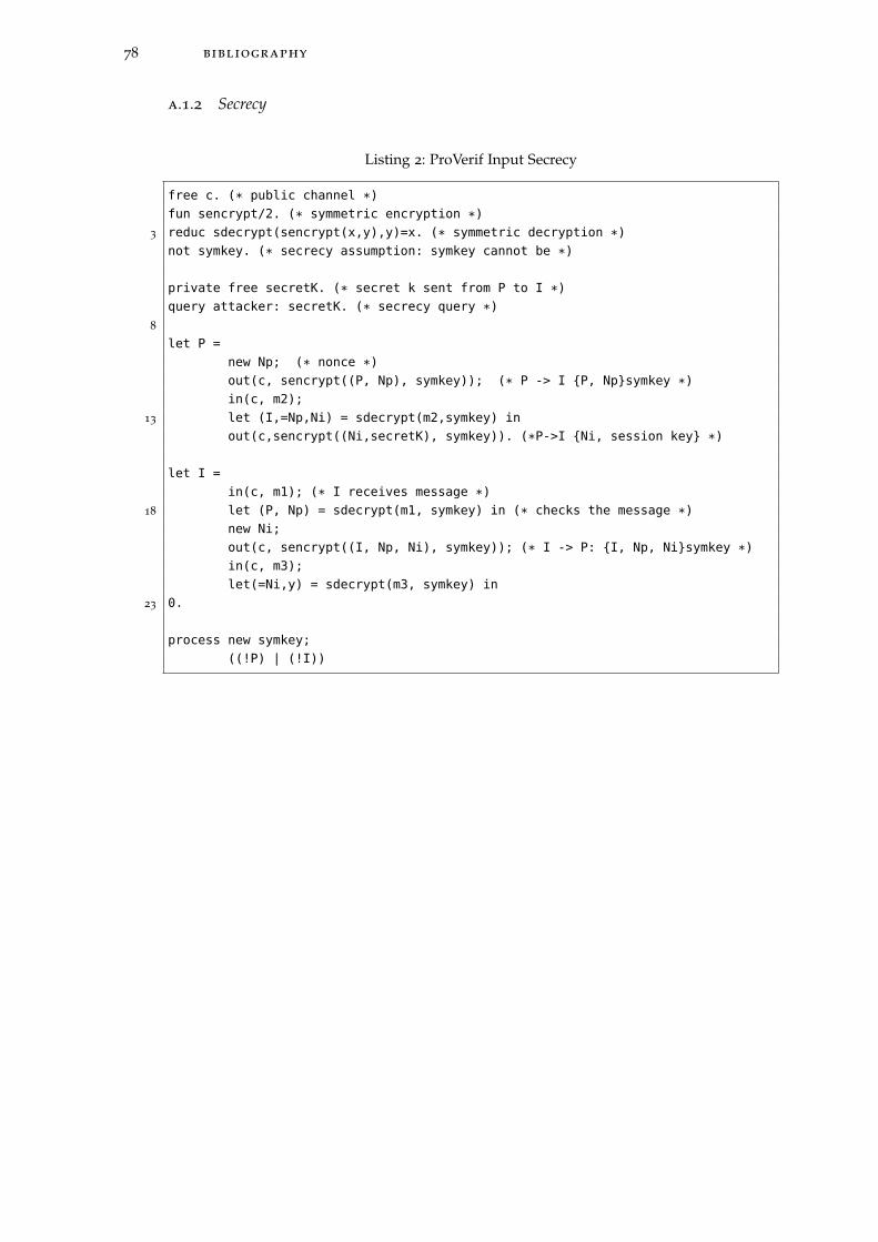
78 bibliography
a.1.2 Secrecy
Listing 2: ProVerif Input Secrecy
free c. (* public channel *)
fun sencrypt/2. (* symmetric encryption *)
3 reduc sdecrypt(sencrypt(x,y),y)=x. (* symmetric decryption *)
not symkey. (* secrecy assumption: symkey cannot be *)
private free secretK. (* secret k sent from P to I *)
query attacker: secretK. (* secrecy query *)
8
let P =
new Np; (* nonce *)
out(c, sencrypt((P, Np), symkey)); (* P -> I {P, Np}symkey *)
in(c, m2);
13 let (I,=Np,Ni) = sdecrypt(m2,symkey) in
out(c,sencrypt((Ni,secretK), symkey)). (*P->I {Ni, session key} *)
let I =
in(c, m1); (* I receives message *)
18 let (P, Np) = sdecrypt(m1, symkey) in (* checks the message *)
new Ni;
out(c, sencrypt((I, Np, Ni), symkey)); (* I -> P: {I, Np, Ni}symkey *)
in(c, m3);
let(=Ni,y) = sdecrypt(m3, symkey) in
23 0.
process new symkey;
((!P) | (!I))
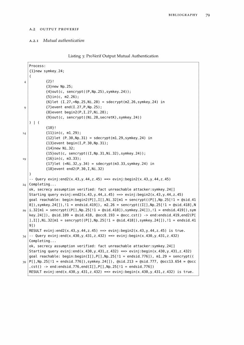
bibliography 79
a.2 output proverif
a.2.1 Mutual authentication
Listing 3: ProVerif Output Mutual Authentication
Process:
{1}new symkey_24;
(
4 {2}!
{3}new Np_25;
{4}out(c, sencrypt((P,Np_25),symkey_24));
{5}in(c, m2_26);
{6}let (I_27,=Np_25,Ni_28) = sdecrypt(m2_26,symkey_24) in
9 {7}event end(I_27,P,Np_25);
{8}event begin2(P,I_27,Ni_28);
{9}out(c, sencrypt((Ni_28,secretK),symkey_24))
) | (
{10}!
14 {11}in(c, m1_29);
{12}let (P_30,Np_31) = sdecrypt(m1_29,symkey_24) in
{13}event begin(I,P_30,Np_31);
{14}new Ni_32;
{15}out(c, sencrypt((I,Np_31,Ni_32),symkey_24));
19 {16}in(c, m3_33);
{17}let (=Ni_32,y_34) = sdecrypt(m3_33,symkey_24) in
{18}event end2(P_30,I,Ni_32)
)
-- Query evinj:end2(x_43,y_44,z_45) ==> evinj:begin2(x_43,y_44,z_45)
24 Completing...
ok, secrecy assumption verified: fact unreachable attacker:symkey_24[]
Starting query evinj:end2(x_43,y_44,z_45) ==> evinj:begin2(x_43,y_44,z_45)
goal reachable: begin:begin2(P[],I[],Ni_32[m1 = sencrypt((P[],Np_25[!1 = @sid_41
8]),symkey_24[]),!1 = endsid_419]), m2_26 = sencrypt((I[],Np_25[!1 = @sid_418],N
29 i_32[m1 = sencrypt((P[],Np_25[!1 = @sid_418]),symkey_24[]),!1 = endsid_419]),sym
key_24[]), @sid_109 = @sid_418, @occ8_193 = @occ_cst() -> end:endsid_419,end2(P[
],I[],Ni_32[m1 = sencrypt((P[],Np_25[!1 = @sid_418]),symkey_24[]),!1 = endsid_41
9])
RESULT evinj:end2(x_43,y_44,z_45) ==> evinj:begin2(x_43,y_44,z_45) is true.
34 -- Query evinj:end(x_430,y_431,z_432) ==> evinj:begin(x_430,y_431,z_432)
Completing...
ok, secrecy assumption verified: fact unreachable attacker:symkey_24[]
Starting query evinj:end(x_430,y_431,z_432) ==> evinj:begin(x_430,y_431,z_432)
goal reachable: begin:begin(I[],P[],Np_25[!1 = endsid_776]), m1_29 = sencrypt((
39 P[],Np_25[!1 = endsid_776]),symkey_24[]), @sid_213 = @sid_777, @occ13_654 = @occ_cst() -> end:endsid_776,end(I[],P[],Np_25[!1 = endsid_776])
RESULT evinj:end(x_430,y_431,z_432) ==> evinj:begin(x_430,y_431,z_432) is true.
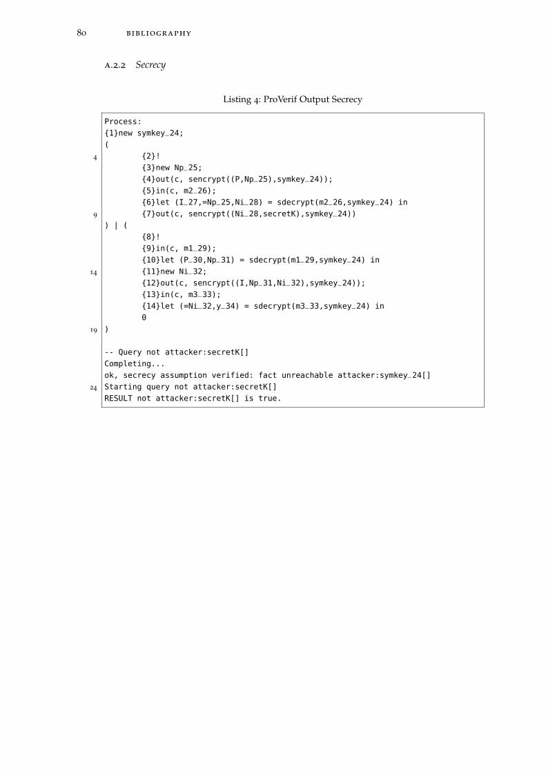
80 bibliography
a.2.2 Secrecy
Listing 4: ProVerif Output Secrecy
Process:
{1}new symkey_24;
(
4 {2}!
{3}new Np_25;
{4}out(c, sencrypt((P,Np_25),symkey_24));
{5}in(c, m2_26);
{6}let (I_27,=Np_25,Ni_28) = sdecrypt(m2_26,symkey_24) in
9 {7}out(c, sencrypt((Ni_28,secretK),symkey_24))
) | (
{8}!
{9}in(c, m1_29);
{10}let (P_30,Np_31) = sdecrypt(m1_29,symkey_24) in
14 {11}new Ni_32;
{12}out(c, sencrypt((I,Np_31,Ni_32),symkey_24));
{13}in(c, m3_33);
{14}let (=Ni_32,y_34) = sdecrypt(m3_33,symkey_24) in
0
19 )
-- Query not attacker:secretK[]
Completing...
ok, secrecy assumption verified: fact unreachable attacker:symkey_24[]
24 Starting query not attacker:secretK[]
RESULT not attacker:secretK[] is true.