Embed Size (px)
Citation preview

A Rule-based Approach to the Implementation ofBusiness Processes in Normalized Systems
Diogo R. FerreiraInstituto Superior Tecnico (IST)University of Lisbon, Portugal
E-mail: [email protected]
Pedro SimoesInstituto Superior Tecnico (IST)University of Lisbon, Portugal
E-mail: [email protected]
Abstract—The theory of Normalized Systems addresses theproblem of developing information systems that can evolve overtime, by guaranteeing that each new feature can be implementedwith a limited number of changes that does not depend onthe actual size of the system. The theory is supported by asoftware architecture that includes a set of five distinct elementsto implement the application logic. One of those elements isthe workflow element, which represents a sequence of actionsand can be used to implement process behavior based on statemachines. In this work, we propose a different approach tothe implementation of process behavior in Normalized Systems.Specifically, the approach is based on the use of rules and eventsas fine-grained elements to build complex behavior. Our previousexperience in the retail industry suggests that such approach iscapable of dealing with the increasing complexity of businessprocesses in that sector. We also discuss some details regardingthe implementation of this new architecture on top of a populartechnological platform and its supporting tools.
Keywords—Normalized Systems, Workflow and Business Pro-cesses, ECA Rules
I. INTRODUCTION
Normalized Systems (NS) [1] is a software engineeringapproach to the development of business information systems,with a special focus on supporting the evolvability of suchsystems. In particular, NS theory requires that it must bepossible to implement any added functionality with a fixednumber of changes, in order to guarantee system-theoreticstability over time [2]. If implementing a new feature requiresan unbounded set of changes, or a number of changes thatdepends on the size of the system, then this is referred to asa combinatorial effect. These effects are undesirable because,as the system grows over time, it will become too difficultand costly to change it. NS theory is a means to avoidcombinatorial effects by design.
This is achieved by adopting a set of design principles and asoftware architecture that is based on the following elements:
• Data element – represents a data entity with primitivefields and possible references to other data entities.
• Action element – represents a functional task that con-sumes and produces data entities as input and output.
• Connector element – encapsulates I/O operations withexternal systems during the execution of an action.
• Workflow element – represents a sequence of actionswhich are called in a stateful way, by keeping statebetween consecutive calls.
• Trigger element – encapsulates the activation of an actionor workflow in an automatic or periodic way.
NS theory ensures stability and evolvability with respect toa set of anticipated changes to these elements. Specifically,NS theory supports incremental changes such as creatingadditional Data elements, creating additional Action elements,adding Actions to Workflow elements, etc.1 Through extensiveuse of the principle of version transparency (whereby anelement can be replaced by a new version without breakingother elements), it can be shown formally that this set ofanticipated changes can be performed on a normalized systemwithout the occurrence of combinatorial effects [2].
A. Problem statementOne of the key elements in this software architecture is the
Workflow element, which allows the embedding of processlogic in a normalized system. Traditionally, this process logicis specified as a state machine that defines a sequencing ofActions, and where the execution of each Action brings theprocess from a previous state into a new state. In this work,we argue that the implementation of process logic in this wayactually goes against some of the fundamental principles onwhich NS theory is built, namely:
• the principle of having a fine-grained modular structurewhich can accommodate changes without requiring anextensive system overhaul;
• the principle of having low coupling between elementsso that a change in one element has the least potential torequire a change in another element.
As a composition of Actions, the Workflow element is acoarse-grained construct when compared to the other elementsin the software architecture. It is also a factor of couplingbetween Actions, since these must bring the workflow from aninitial state to a desired final state, with every state in betweenbeing both the output state of an Action and the input state ofanother Action. This creates a tightly coupled set of Actionswhich, in general, will be difficult to reuse in other workflowsor even in different versions of the same workflow. If there isa change in the process logic, then this change may create acombinatorial effect that depends on the size of the workflow.
1In this paper we use capitalized words (e.g. Action) when we refer tospecific elements in the software architecture of NS. We use non-capitalizedwords (e.g. action) to refer to general concepts beyond the context of NS.

B. Contribution
The goal of this work is to support changes in process logicwhile avoiding those combinatorial effects. For this purpose,we extend the software architecture of normalized systemswith two complementary perspectives: the structural perspec-tive, and the behavioral perspective. While the structuralperspective is based on the usual Data and Action elements,the behavioral perspective introduces new elements, namelythe Event element and the Rule element. As will be shown,Events and Rules are the behavioral counterpart of structuralelements such as Data and Actions. The purpose of introducingthese new elements is to create a fine-grained structure forimplementing process behavior. This is illustrated by meansof an application scenario in the retail industry, and we alsodiscuss some details regarding its implementation.
C. Paper structure
The paper is organized as follows: Sections II and IIIdiscuss two important principles that justify the need for thebehavioral perspective and also the use of events and rules.Section IV shows that these rules are conceptually similarto traditional ECA rules. Section V describes the proposedarchitecture, its software elements, the anticipated changes onthose elements, and their run-time interactions. Section VIdescribes the application scenario in the retail industry wherethe proposed architecture supports several changes to a salesprocess. Finally, Section VII discusses the implementation ofa new development framework for normalized systems basedon the proposed architecture.
II. DUALITY OF STRUCTURE AND BEHAVIOR
In the late 1970s, Data Flow Diagrams (DFDs) [3], [4] be-came a popular tool for system analysis and design. Basically,DFDs described the data flows across system functions; in theYourdon/DeMarco notation [3], functions were represented ascircles and data flows were represented as arrows betweencircles. For this technique to be effective, it required thesystem to be properly divided into a set of functions; therefore,having a correct functional decomposition of the system wasas important as having a correct specification of the data flows.In other words, the structural and behavioral perspectives ofthe system were developed in tandem.
Later developments in object-oriented modeling and de-sign [5] have seen such functional decomposition being refinedinto class diagrams, which brought a significant advance inthe structural perspective. On the other hand, the behavioralperspective was being developed more in the realm of processmodeling and workflow management [6], although withoutsettling on a standard language, as each workflow system usedits own modeling language. The development of UML [7]brought the structural and behavioral perspectives under acommon umbrella, but in separate diagrams; and the effortsto define a standard process modeling language eventually ledto BPMN [8], which has some similarities to UML ActivityDiagrams, but has been growing to address specific needsrelated to the modeling of business processes.
The point that we would like to make here is that theneed for functional decomposition (structural perspective) andprocess modeling (behavioral perspective) have always beenpresent in system analysis and design. One cannot go withoutthe other, and if in NS theory the structural perspectiveis addressed with Data and Action elements for functionaldecomposition, the same cannot be said about the behavioralperspective, where it lacks an equivalent set of fine-grainedelements. In this work, we introduce Events and Rules inthe behavioral perspective, as the dual elements of Data andActions in the structural perspective.
III. DUALITY OF STATES AND EVENTS
In the original NS theory [1], processes are modeled asa state machine where the transition between states takesplace through the execution of Actions. Therefore, a statecorresponds to the moment in time when the execution ofan Action has just finished but the execution of the followingAction has not yet begun. In this context, the execution of aAction plays the same role as an event that causes a transitionfrom one state to another. There is one such event between anytwo consecutive states, and there is always a state between twoconsecutive events. This mutual relationship between statesand events is illustrated in Figure 1.
State a State b State cEvent 1 Event 2... ...Event 3
Fig. 1. States and events
The duality between states and events also exists in otherprocess modeling languages. For example, in Petri nets [9]there are places and transitions which play a similar role tothe states and events depicted in Figure 1 (even the notationis similar, since places are drawn as circles and transitions areusually drawn as thick bars or rectangles).
This means that whatever behavior that is specified as aset of states can also be described by focusing instead onthe events between those states. The two descriptions areequivalent, and this duality has led to two different approachesto process modeling, namely graph-based approaches that arebased on states and activities, and rule-based approaches thatare based on events and rule processing. A survey of thesemodeling approaches can be found in [10].
For the purpose of modeling process behavior in normalizedsystems, the difference between the graph-based approach andthe rule-based approach can become significant. The graph-based approach favors the definition of the process as a whole,leading to a coarse-grained construct (e.g. a workflow engine,or the Workflow element) that controls process execution fromend to end. On the other hand, the rule-based approach favorsa decentralized, piecewise definition of the process, where thebehavior emerges from the collective effect of the applicationof several rules. These rules (and their firing events) are fine-grained constructs that can be combined in several ways toimplement a variety of workflow patterns.

IV. ECA RULES
The idea of using Event-Condition-Action (ECA) rules todefine and implement process behavior goes back to the 1990s,with pioneering works such as TriGSflow [11], WIDE [12],SWORDIES [13], and EVE [14]. Since then, several authorshave proposed and discussed the benefits of using ECA rulesfor describing and implementing business processes [15]–[17].Among these benefits, there are some characteristics of ECArules that are widely recognized and that are of special interestin the context of normalized systems:
• ECA rules are inherently flexible in the sense that theycan be changed or adapted to new requirements, and itmight even be possible to do this without interruptingrunning processes.
• ECA rules deal with error handling and exceptions in anatural way. Since errors and exceptions are also events,the rules to handle them can be defined in a similar wayto any other rule.
• In traditional graph-based approaches, the transition to anew state usually occurs upon completion of an activity.However, with a rule-based approach it is possible for asingle activity to be the source of multiple events, withnew rules being fired at any point during execution.
Basically, an ECA rule has the following form:
ON event IF condition THEN action
This means that when a certain event occurs, a condition isevaluated and, if the condition is true, some action is invoked.When the action raises an event, another rule will be fired,creating a chain of actions and events that is the basis forimplementing sequential behavior.
Other common workflow patterns, such as those foundin [18], can also be implemented. For example, an AND-split(parallelism) can be implemented with two rules that are firedby the same event but execute different actions. As anotherexample, a XOR-split (branching) can be implemented withtwo rules that react to the same event but the condition of one
rule is the logical negation of the other, so that only one actionwill be performed.
In some application scenarios, it may be useful to extendECA rules with multiple events, multiple conditions, and/ormultiple actions. With multiple events it is possible, forexample, to have AND-joins (synchronization), such as havinga rule that is fired only after two different events have occurred;with multiple conditions it is possible to have more elaborateexpressions to decide whether to execute an action or not;and with multiple actions it is no longer necessary to definemultiple rules when several activities must be done in responseto the same event/condition.
In our proposed architecture, we will use these extensions ina purely AND-logic, meaning that every event must occur andevery condition must be true in order to execute every action;otherwise, no action will be executed at all. An OR-logic canbe built by defining multiple, alternative rules (i.e. rules thatrespond to different events, or rules that respond to the sameevent but have different conditions). At this point, it shouldbe noted that the firing of rules is non-deterministic, i.e. thereis no predefined order for the evaluation of rules that are firedby the same event/condition.
V. PROPOSED ARCHITECTURE
Figure 2 illustrates the proposed architecture, which com-prises a structural perspective and a behavioral perspective.The structural perspective contains the standard Data andAction elements from NS theory, which provide a fine-grainedstructure for the functional decomposition of a system. Onthe other hand, the behavioral perspective introduces the newEvent and Rule elements to provide a fine-grained structurefor the implementation of process behavior.
The standard Connector and Trigger elements are alsoincluded, albeit in different perspectives. The Connector el-ement supports the interaction with external systems; sinceConnectors are called by Actions, they have been includedin the structural perspective. On the other hand, the Triggercaptures events of interest from the outside; since Triggers
ActionData Event Rule
Connector Trigger
Data store
Externalsystem
Structure Behavior
produces/consumes raises
creates
fires
invokes
carries
uses
Existing elements in NS theory
New elements
Fig. 2. Overview of the proposed architecture

FieldElement
Type : string
DataElement
Fields : FieldElement[]
Element
Name : stringVersion : integer
ActionElement
Data : DataElement[]Events : EventElement[]
execute()
EventElement
Data: DataElement[]
ConditionElement
Events : EventElement[]
evaluate()
RuleElement
Events : EventElement[]Conditions : ConditionElement[]Actions : ActionElement[]
Fields
Events
Data
Events
Data
Conditions
Actions
Events
* * * *
*
*
*
*
Existing elements in NS theory
New elements
{ (Event ϵ Condition) ˄ (Condition ϵ Rule) => (Event ϵ Rule)}
Fig. 3. Class diagram with inheritance and aggregation relationships
instantiate Events that fire Rules, they have been included inthe behavioral perspective.
The way these elements interact with each other can bedescribed as follows:
• Actions manipulate Data. Data elements can be bothconsumed and produced by Actions, as in standard NStheory. However, here we introduce another kind ofoutput from Actions: Events.
• Actions raise Events. The most common scenario is foran Action to raise an Event upon completion. However,it is also possible for an Action to generate Events at anypoint during its execution.
• Events carry Data. An Event has a payload comprisingzero, one, or more Data elements. Such Data are insertedin the Event when it is created. Once the Event is raised,its payload can no longer be changed.
• Events fire Rules. Once an event is raised, there may bezero, one, or more Rules that are listening for that Event.All such rules will be evaluated concurrently, in non-deterministic order.
• Rules have Conditions. Conditions are logical expressionsover the content of Data elements carried by Events. If aRule has multiple conditions, all those expressions mustevaluate to true for the Rule to execute its Actions.
• Rules invoke Actions. A Rule may execute a set of one ormore Actions. Execution is asynchronous, meaning thatthe Rule invokes each Action and returns immediatelywithout waiting for the Action to complete.
• Rules pass Data as input to Actions. When a Rule invokesan Action, it may pass zero, one, or more Data elementsas input. Each of these Data elements must have beenbrought to the Rule by one of its firing Events.
• Connectors and Triggers support external interactions.Connectors support interactions initiated from the inside,and Triggers support interactions initiated from the out-
side. Asynchronous interaction patterns such as request-response and solicit-response [19] can be implementedthrough a combination of Triggers and Connectors.
Figure 3 provides a more detailed view of these elementsand the relationships between them. For brevity, only inheri-tance and aggregation relationships are shown; Connector andTrigger elements have also been left out.
One of the fundamental principles of NS theory is versiontransparency [2], and this principle is supported here by havingall elements descend from the base class Element, whichprovides a Name and Version.
A number of subclasses are derived from this base class.There are two additional elements that have been included tofurther refine this structure: one is the Field element, which is acomponent of the Data element, and the other is the Conditionelement, which is a building block of Rules.
In the Data element, the purpose of having Fields is tosupport changes in data types and also the addition/removalof Fields in a Data element, which are common changes inpractice. In the Condition element, there is a list of Eventsto indicate which Events (actually, their Data) will be neededto evaluate the Condition. If a Rule has a Condition and thatCondition needs certain Events, then these Events must belongto the set of firing Events of that Rule. We indicated thisrestriction with a constraint in the diagram.
For each element depicted in Figure 3, the list of anticipatedchanges is as follows:
• Field element – change of data type;• Data element – addition and removal of Fields;• Event element – addition and removal of Data;• Action element – addition and removal of Data and
Events;• Condition element – addition and removal of Fields;• Rule element – addition and removal of Events, Condi-
tions and Actions.

From this description, it may appear that we support boththe addition and removal of elements, while the original NStheory supports only additions and treats removals as a matterof garbage collection [20]. In fact, what we support here isthe removal of a reference from a list or array of references.The element itself continues to exist while there are referencesto it. When the last reference is removed, it can be garbagecollected, as advocated by standard NS theory.
VI. APPLICATION SCENARIO
To illustrate how the proposed architecture can be appliedin practice, we turn to our previous experience in the retailindustry. For many years, the retail industry was a relativelystraightforward type of business, but the introduction of pro-motional campaigns and customer loyalty programs signifi-cantly increased the complexity of this business. Nowadays,the retail industry is characterized as being a highly dynamicbusiness environment, where there is a constant struggle tomaintain a leading edge over competitors. In terms of ITand supporting systems, it is common to spend several weeksor even months on the implementation of a new feature, tobe used in a customer engagement campaign that lasts onlytwo weeks or even less. NS theory seems to be a perfect fitto deal with the fast pace at which requirements change inthis scenario, especially when focusing on the promotions andcustomer loyalty systems.
A. Sales process without promotions
In the first stage of this case study, we focus on a salesprocess without any promotional campaigns. The goal is toidentify the basic software elements that will also be used insubsequent stages, where the sales process grows in complex-ity as promotional campaigns are added.
The process will have to interact with an external point-of-sale (POS) system2, which raises different kinds of events:
• BeginSaleEvent – this marks the beginning of a salestransaction, and is equivalent to the beginning of a newtransaction in a database system.
• AddProductEvent – this marks the moment when a prod-uct is added to the sales basket. It can also be usedto remove products from the basket, if the quantity isnegative. Usually, a product is introduced (or cancelled)by scanning a barcode or by manual input on the POSkeypad. Other variants involve the manual introductionof quantity, dynamic barcodes (for multiple units of thesame product in a single pack) and weight scales (forproducts sold by weight).
• RequestTotalEvent – when all products have been intro-duced in the basket and the customer is ready to pay, thePOS system requires an intermediate operation with thepurpose of calculating all the sales subtotals and presentthe final value to the customer.
2For an example of a POS system, see e.g.: https://www.toshibatec-ris.com/products overseas/pos system/. (TOSHIBA TEC Retail Information Systemsis currently a leading provider of POS solutions after having acquired IBM’sPOS terminal business in 2012.)
• AddPaymentEvent – when the sale has been paid, thePOS system requires the execution of an operation toregister the payment and update the basket accordingly.
• EndSaleEvent – this marks the end of a sales transaction,and is equivalent to a commit in a database system.
Table I shows these Events together with the Rules that theyfire, the Actions invoked by those Rules, and the output Eventsraised by those Actions.
TABLE IELEMENTS FOR THE SALES PROCESS
POS Event Rule Action Raised Events
BeginSaleEvent BeginSaleRule BeginSaleActionBeginSaleSuccessBeginSaleFail
AddProductEvent AddProductRule AddProductActionAddProductSuccessAddProductFail
RequestTotalEvent RequestTotalRule RequestTotalActionRequestTotalSuccessRequestTotalFail
AddPaymentEvent AddPaymentRule AddPaymentActionAddPaymentSuccessAddPaymentFail
EndSaleEvent EndSaleRule EndSaleActionEndSaleSuccessEndSaleFail
At this stage, the process is mostly concerned with the man-agement of data in the basket. These data can be representedas one or more Data elements as shown in Figure 4. TheAddProductAction appends a new SalesLine to the Basket, andthe AddPaymentAction sets the PaymentLine in the Basket.
SalesLinesPayment
Basket
SalesLines : SalesLine[]Payment : PaymentLineTotal : decimal
SalesLine
Barcode : stringDescription : stringQuantity : decimalUnitPrice : decimal
PaymentLine
Code : stringDescription : stringValue : decimal
*
Fig. 4. Data elements for the sales basket (simplified)
B. Sales process with direct discounts
In the second stage of this case study, we modify the salesprocess to include the possibility of having direct discountson some products. These are the simplest kind of promotionsin the retail sector, so they are a good candidate to illustratean incremental evolution of the previous process.
Typically, the way to implement direct discounts in the retailindustry is to have a list of existing promotions and, givena particular basket, to look for applicable promotions to theproducts contained in that basket. For this purpose, we need tointroduce a new Data element to represent a direct promotion.In addition, the Basket will now have two more attributes andeach SalesLine may have a reference to a Promotion. The newdata elements are illustrated in Figure 5.
The implementation of direct discounts requires the intro-duction of two new Rules. A first Rule checks whether there

*
M4SalesLines
Basket.Version2
SalesLines : SalesLine[]Payment : PaymentLineSubTotal : decimalDiscountTotal : decimalTotal : decimal
SalesLine.Version2
Barcode : stringDescription : stringQuantity : decimalUnitPrice : decimalPromotion : PromotionDiscount : decimal
Promotion
Code : stringBarcode : stringType: {percentage|value|fixedprice}Discount : decimal
Promotion
Fig. 5. Data elements for direct discount promotions
is a promotion for a product (SalesLine) that has just beenadded to the Basket. If a promotion is found, then a secondRule applies the discount to that SalesLine. Table II shows thenew elements to be added to the sales process.
TABLE IIADDITIONAL ELEMENTS FOR DIRECT DISCOUNTS
Event Rule Action Raised Events
AddProductSuccess FindPromotionRule FindPromotionActionFindPromotionSuccessFindPromotionFail
FindPromotionSuccess ApplyPromotionRule ApplyPromotionActionApplyPromotionSuccessApplyPromotionFail
C. Sales process with “take x, pay y” promotions
In the third stage of this case study, we focus on thepossibility of having a different type of promotion which takesinto account multiple sales lines in the basket. This type ofpromotions are usually called basket promotions.
The “take x, pay y” promotion is a well-known basketpromotion that allows a customer to buy x units of a certainproduct but pay only a fraction (y/x) of their total price. Thisis implemented by having two dedicated fields: one is theTakeQuantity field which stores the minimum product quantitythat must exist in the basket in order to apply this promotion;the other field is OfferQuantity, which defines how muchquantity is offered to the customer every time the promotionis applied. Applying this promotion results in a discount beingadded to one or more sales lines.
Since individual sales lines can be canceled during a sale,the application of this promotion must occur at a later stageof the sale transaction, when the amount of products in thebasket can no longer change. Therefore, this promotion mustbe applied on the RequestTotalEvent, after all products havebeen scanned and the basket is considered closed.
With the introduction of this new promotion, the possibilityof having multiple promotions targeted at the same productarises and a conflict can occur. Therefore, promotions mustbe prioritized, which requires the use of a Priority field. Thecalculation of direct discount promotions as products are beingscanned can be maintained but, when the total is requested,other promotions can prevail, overriding the existing directdiscount promotions.
For example, given two promotions targeted at the sameproduct – a direct promotion offering a 10% discount with
*
SalesLines
Basket.Version2
SalesLines : SalesLine[]Payment : PaymentLineSubTotal : decimalDiscountTotal : decimalTotal : decimal
SalesLine.Version2
Barcode : stringDescription : stringQuantity : decimalUnitPrice : decimalPromotion : PromotionDiscount : decimal
DirectDiscountPromotion
Type: {percentage|value|fixedprice}Discount : decimal
TakeXPayYPromotion
TakeQuantity : integerOfferQuantity : integer
Promotion.Version2
Code : stringBarcode : stringPriority : integer
Promotion
Fig. 6. Data elements for “take x, pay y” promotions
priority 2; and a “take 3, pay 2” promotion with priority 1(higher priority) – then the direct discount of 10% will beoffered at each input of such product, but if there are 3 unitsor more of that product in the basket, the second promotionwill replace the first promotion when the total is requested.
The implementation of basket promotions requires a refac-toring of the data elements in order to introduce a new versionof the Promotion data element that can support both types ofpromotions, as illustrated in Figure 6.
In particular, the new Promotion element contains the fieldsthat are common to both promotions (Code for the promotioncode, and Barcode for the product code) as well as anadditional field to indicate Priority. For direct promotions, theType and Discount fields continue to exist, but are now placedin a subclass of Promotion. The same happens with “take x,pay y” promotions, which have their own separate subclasswith TakeQuantity and OfferQuantity fields.
Finally, to support basket promotions it is necessary tointercept the RequestTotalEvent and execute intermediate ac-tions to find and apply matching promotions based on productquantities, before the actual total is calculated by RequestTo-talAction. Table III shows the changes to the process.
TABLE IIICHANGES TO SUPPORT BASKET PROMOTIONS
Event Rule Action Raised Events
RequestTotalEvent FindBasketPromRule FindBasketPromActionFindBasketPromSuccessFindBasketPromFail
FindBasketPromSuccess ApplyBasketPromRule ApplyBasketPromActionApplyBasketPromSuccessApplyBasketPromFail
ApplyBasketPromSuccess RequestTotalRule RequestTotalActionRequestTotalSuccessRequestTotalFail
VII. IMPLEMENTATION
Originally, the development framework for normalized sys-tems was implemented over a J2EE platform based on Javatechnology and structured as a 4-Tier Web application ar-chitecture [1]. Unfortunately, this reference implementationis not publicly available, making it difficult for the widercommunity to understand how the concepts of NS theory can

be transformed into actual application code. Our approachin this work was to develop a prototype implementation ofthe proposed architecture by leveraging the rapid prototypingcapabilities of the .NET Framework and Visual Studio.
In particular, the C# programming language, the .NETFramework, and the Visual Studio IDE were chosen for thefollowing main reasons:
• the .NET compilers and certain components of the .NETFramework have been recently open-sourced3;
• it is possible to achieve a tight integration with VisualStudio through its SDK4 and extensibility tools;
• it provides sophisticated code-generation capabilitiesthrough the use of T4 templates5;
• in general, this platform and its tools offer great capabil-ities for rapid application development (RAD).
A. Defining the software elements
In our implementation, the software elements (Data, Ac-tions, Events, Rules, etc.) are defined in an XML6 file which isthen validated against an XSD7 schema definition. This XSDschema defines each element as a complexType that containsattributes and sequences of other elements. For example, theData element extends a base type Element (which providesName and Version), and contains a sequence of Field Ele-ments. In essence, the XSD schema enforces the inheritanceand aggregations relationships shown earlier in Figure 3.
A series of integrity constraints are also enforced after XSDvalidation. For example, one of such constraints is the oneindicated in Figure 3: if an Event belongs to a Condition, andthe Condition belongs to a Rule, then the Event must alsobelong to the Rule. Some constraints could have been verifiedusing key and keyref mechanisms available in XSD. However,for more complicated constraints, such as the one above, itbecomes more convenient to check them using C# and LINQ8.With LINQ, we write queries over object collections in orderto verify that the element definitions are free of errors.
The process of translating the XML descriptor file intoactual application code involves a series of stages as illustratedin Figure 7:
1) Syntactic checks: the XML descriptor file is saved with a.nsd extension and is validated against the XSD schema.
2) Definition instantiation: the elements in the XML de-scriptor file are instantiated as C# objects using XMLdeserialization.
3) Semantic checks: integrity constraints are verified on theobject instances with the help of C# and LINQ.
4) Template expansion: the source code is generated withthe application of T4 templates to the object instancescreated from the XML descriptor file.
3Project “Roslyn” on GitHub.4Software Development Kit (SDK)5Text Template Transformation Toolkit (T4)6Extensible Markup Language (XML)7XML Schema Definition (XSD)8Language-Integrated Query (LINQ)
Stage 1: Syntactic check
Stage 2: Definition instantiation
Stage 3: Semantic checks
Stage 4: Template expansion
XSD validation
XML deserialization
C# + LINQ
T4 -> C# code
XML descriptor(.nsd file)
Schemadefinition(.xsd file)
Source code
(.cs file)
T4 template(.tt file)
Fig. 7. Processing stages for code generation
B. Template expansion
Once the first three stages are complete, the element defi-nitions have been transformed into C# objects in memory. Wethen use a set of T4 templates (one for each type of element)to generate the source code for the application. Initially, weconsidered the option of using XSLT9 to generate the sourcecode from the XML descriptor file, but T4 revealed to be moreadequate in this scenario.
In essence, a T4 template is a mixture of text blocks andcontrol blocks that specify how to generate an output text file.For example, a T4 template can generate multiple repetitionsof the same text block by means of a control block with aloop. The generated output can be a text file of any kind, suchas a Web page, a resource file, or program source code in anylanguage. A T4 template can therefore be seen as a “program”that generates source code.
In our T4 template, both the text blocks (the source codeto be generated) and the control blocks (the instructions togenerate the code) are written in C#. The T4 template isprocessed by special component available in Visual Studio,called TextTemplatingFilePreprocessor. Given the T4 template anda set of C# objects (the element definitions), the TextTemplating-FilePreprocessor generates the source code for the applicationbased on the properties of those objects.
C. Custom tool
The four stages depicted in Figure 7 are implemented ina custom tool that we developed for Visual Studio. Thiscustom tool is invoked whenever there is a change to theXML descriptor file. In this case, it re-generates the applicationsource code automatically.
9Extensible Stylesheet Language Transformations (XSLT)
The custom tool was developed as a COM10 componentthat implements the IVsSingleFileGenerator interface. Throughthis interface, a custom tool transforms a single input fileinto a single output file. When the input file is saved, thecustom tool is instantiated and Visual Studio calls its Generatemethod, passing a reference to an IVsGeneratorProgress callbackinterface that the tool can use to report its progress. This isused to provide feedback on the expansion process.
The output generated by the custom tool (i.e. the appli-cation source code) is added to the project together with adependency to the input descriptor file.
D. Visual Studio extensions
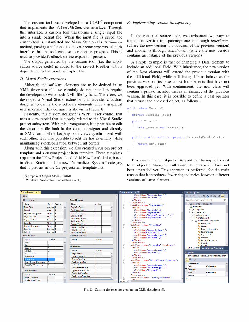
Although the software elements are to be defined in anXML descriptor file, we certainly do not intend to requirethe developer to write such XML file by hand. Therefore, wedeveloped a Visual Studio extension that provides a customdesigner to define those software elements with a graphicaluser interface. This designer is shown in Figure 8.
Basically, this custom designer is WPF11 user control thatuses a view model that is closely related to the Visual Studioproject subsystem. With this arrangement, it is possible to editthe descriptor file both in the custom designer and directlyin XML form, while keeping both views synchronized witheach other. It is also possible to edit the file externally whilemaintaining synchronization between all editors.
Along with this extension, we also created a custom projecttemplate and a custom project item template. These templatesappear in the “New Project” and “Add New Item” dialog boxesin Visual Studio, under a new “Normalized Systems” categorythat is present in the C# project/item template list.
10Component Object Model (COM)11Windows Presentation Foundation (WPF)
E. Implementing version transparency
In the generated source code, we envisioned two ways toimplement version transparency: one is through inheritance(where the new version is a subclass of the previous version)and another is through containment (where the new versioncontains an instance of the previous version).
A simple example is that of changing a Data element toinclude an additional Field. With inheritance, the new versionof the Data element will extend the previous version withthe additional Field, while still being able to behave as theprevious version (its base class) for elements that have notbeen upgraded yet. With containment, the new class willcontain a private member that is an instance of the previousversion. In this case, it is possible to define a cast operatorthat returns the enclosed object, as follows:
public class Version2{
private Version1 _base;
public Version2(){
this._base = new Version1();}
public static implicit operator Version1(Version2 obj){
return obj._base;}
}
This means that an object of Version2 can be implicitly castto an object of Version1 in all those elements which have notbeen upgraded yet. This approach is preferred, for the mainreason that it introduces fewer dependencies between differentversions of same element.
Fig. 8. Custom designer for creating an XML descriptor file

F. Customizations and harvesting
The generated code is a skeleton for the target application,and the developer will need to add custom code to the project.Rather than changing the generated code (which will be re-generated at each new change to the XML descriptor file),any custom code is kept in separate source files. The C#language provides a convenient mechanism to allow this codeseparation: using partial classes [21] it is possible to have aclass definition split across multiple source files.
All of the generated C# classes are declared as partialto provide the possibility of being extended with additionalsource files that the developer adds to the project. Thismethod of using partial classes when dealing with generatedcode is available since .NET Framework 2.0 and is a well-established practice nowadays. For example, it is used byWinForms, WPF, ASP.NET Web Forms, and many other toolsand designers available in the Visual Studio environment.
Using C# with partial classes avoids having to deal with theproblem of harvesting [22], which consists in extracting anycustom code from a previous version and re-inserting it into anew version of the application. In our framework, harvestingis unnecessary for the following reasons:
• there is no need to edit the generated source code to injectcustom code;
• there is no need to have anchor points because the customcode resides in a separate file;
• the custom code will not be lost with a new expansionof the descriptor file.
G. Rule engine
The application code (with both the generated and thecustom code) is compiled and linked to a library that pro-vides common functionality for all target applications basedon our implementation framework. An essential part of thatcommon functionality is the rule engine, i.e. the componentthat manages the execution of the target application at run-time. This rule engine is based on an event queue on a ruleinstantiation mechanism, as depicted in Figure 9.
Rule 1Rule 1
Rule 1Rule 1
Rule 1Rule 1
Rule 1Rule 1
Rule 1Rule 1
Rule 1Rule 2
Event 2
Event 1
Event 1
Eventqueue
Action
Incomingevents
Ruleinstantiation
corr. idcorr. id
corr. id
corr. id
select bycorr. id
new instance
Fig. 9. Rule engine
First, we consider the scenario where each Rule is fired bya single Event. In this case, the rule engine retrieves an Eventfrom the queue (in FIFO12 order) and searches for Rules thatare waiting for such Event. It then instantiates such Rules,evaluates their Conditions, and invokes their Actions if theConditions yield true. In turn, these Actions will generate newEvents that will be added to the queue. In the meantime, theprevious Rule instances can be discarded.
For Rules that are waiting for multiple Events, the Rule isinstantiated upon the occurrence of the first Event, and suchinstance is left alive, waiting for the remaining events to arrive(no Conditions are evaluated at this point). The next Event toarrive must have the same correlation id as the first Eventin order to be associated with that particular Rule instance.Once all of the required Events with the same correlation idhave arrived, the Rule instance is fired, i.e. its Conditions areevaluated and its Actions are invoked.
When a Rule instance invokes an Action, it passes its owncorrelation id to the Action. In turn, the Action will insertthis correlation id into any Events that it generates duringits execution. This same correlation id will be used as thecorrelation id for any new Rule instances that are created fromsuch Events. In general, Rule instances are selected by thecorrelation id of the incoming Event. If no Rule instance withsuch correlation id exists, a new one is created.
The use of correlation ids is an import mechanism in serviceinteractions [23], where it is often necessary to associate anincoming message with a specific service instance. Here weuse this mechanism to associate an incoming Event with a Ruleinstance. This allows multiple instances of the same businessprocess to be active at the same time, since the Events andRules from one process instance are managed separately fromthe Events and Rules of other process instances.
VIII. CONCLUSION
In this paper we have proposed an improved architecture forNormalized Systems based on the idea of using ECA rules toimplement process behavior. This is in contrast with currentNS theory, which uses a graph-based approach to control pro-cess execution. There has been an ongoing debate in the pasttwo decades about the advantages of implementing businessprocesses with rule-based vs. graph-based approaches. Withoutgetting too much into that debate, we observe that a rule-based approach fits better with the fundamental principles ofNS theory, which strives for low-coupling and aims at a fine-grained structure to support changes.
Using an application scenario that draws on practical ex-perience in the retail industry, we have illustrated how thisrule-based approach facilitates the accommodation of changesto a business process and supports its increasing complexityover time. Our current and future work is focused on a proto-type implementation of the proposed architecture by takingadvantage of specific features of the C# language and theextensibility of its development environment in order to bringthe benefits of NS theory to a wider range of applications.
12First in, first out (FIFO)

REFERENCES
[1] H. Mannaert and J. Verelst, “Normalized systems: Re-creating infor-mation technology based on laws for software evolvability,” Koppa,Belgium, 2009.
[2] H. Mannaert, J. Verelst, and K. Ven, “The transformation of require-ments into software primitives: Studying evolvability based on systemstheoretic stability,” Science of Computer Programming, vol. 76, no. 12,pp. 1210–1222, 2011.
[3] T. DeMarco, Structured Analysis and System Specification. PrenticeHall, 1979.
[4] C. Gane and T. Sarson, Structured Systems Analysis: Tools and Tech-niques. Prentice Hall, 1979.
[5] J. Rumbaugh, M. Blaha, W. Premerlani, F. Eddy, and W. Lorensen,Object-oriented modeling and design. Prentice Hall, 1991.
[6] D. Georgakopoulos, M. Hornick, and A. Sheth, “An overview ofworkflow management: From process modeling to workflow automationinfrastructure,” Distributed and Parallel Databases, vol. 3, no. 2, pp.119–153, April 1995.
[7] G. Booch, J. Rumbaugh, and I. Jacobson, The Unified Modeling Lan-guage User Guide. Addison Wesley, 1999.
[8] D. Miers and S. A. White, BPMN Modeling and Reference Guide.Future Strategies Inc., 2008.
[9] W. M. P. van der Aalst, “The application of Petri nets to workflowmanagement,” Journal of Circuits, Systems and Computers, vol. 8, no. 1,pp. 21–66, 1998.
[10] R. Lu and S. Sadiq, “A survey of comparative business process modelingapproaches,” in Business Information Systems, ser. LNCS, vol. 4439.Springer, 2007, pp. 82–94.
[11] G. Kappel, B. Proll, S. Rausch-Schott, and W. Retschitzegger, “TriGS-flow: Active object-oriented workflow management,” in Proceedings ofthe 28th Hawaii International Conference on System Sciences, vol. 2,1995, pp. 727–736.
[12] S. Ceri, P. Grefen, and G. Sanchez, “WIDE – a distributed architecturefor workflow management,” in 7th International Workshop on ResearchIssues in Data Engineering, 1997.
[13] R. Endl, G. Knolmayer, and M. Pfahrer, “Modeling processes andworkflows by business rules,” in 1st European Workshop on Workflow
and Process Management. Zurich, Switzerland: Swiss Federal Instituteof Technology (ETH), October 1998.
[14] A. Geppert and D. Tombros, “Event-based distributed workflow execu-tion with EVE,” in Proceedings of the IFIP International Conferenceon Distributed Systems Platforms and Open Distributed Processing(Middleware ’98). Springer, 1998, pp. 427–442.
[15] A. Goh, Y.-K. Koh, and D. Domazet, “ECA rule-based support forworkflows,” Artificial Intelligence in Engineering, vol. 15, no. 1, pp.37–46, 2001.
[16] J. Bae, H. Bae, S.-H. Kang, and Y. Kim, “Automatic control of workflowprocesses using ECA rules,” IEEE Transactions on Knowledge and DataEngineering, vol. 16, no. 8, pp. 1010–1023, 2004.
[17] F. Bry, M. Eckert, P.-L. Patranjan, and I. Romanenko, “Realizingbusiness processes with ECA rules: Benefits, challenges, limits,” inPrinciples and Practice of Semantic Web Reasoning, ser. LNCS, vol.4187. Springer, 2006, pp. 48–62.
[18] W. van der Aalst, A. ter Hofstede, B. Kiepuszewski, and A. Barros,“Workflow patterns,” Distributed and Parallel Databases, vol. 14, no. 1,pp. 5–51, 2003.
[19] M. Brambilla, S. Ceri, M. Passamani, and A. Riccio, “Managing asyn-chronous Web services interactions,” in IEEE International Conferenceon Web Services, 2004, pp. 80–87.
[20] H. Mannaert, J. Verelst, and K. Ven, “Towards evolvable softwarearchitectures based on systems theoretic stability,” Software: Practiceand Experience, vol. 42, no. 1, pp. 89–116, 2012.
[21] K. Czarnecki, M. Antkiewicz, and C. H. P. Kim, “Multi-level customiza-tion in application engineering,” Communnications of the ACM, vol. 49,no. 12, pp. 60–65, December 2006.
[22] G. Oorts, P. Huysmans, P. De Bruyn, H. Mannaert, J. Verelst, andA. Oost, “Building evolvable software using normalized systems theory:A case study,” in 47th Hawaii International Conference on SystemSciences, 2014, pp. 4760–4769.
[23] W. M. P. van der Aalst, A. J. Mooij, C. Stahl, and K. Wolf, “Serviceinteraction: Patterns, formalization, and analysis,” in Formal Methods
for Web Services, ser. LNCS, vol. 5569. Springer, 2009, pp. 42–88.


![Sequence Partitioning for Process Mining with ... - web.ist.utl.ptweb.ist.utl.pt/~diogo.ferreira/papers/walicki11sequence.pdf · A wide range of process mining techniques [4] has](https://img.dokumen.tips/doc/110x75/60098efabe7b15544f1b64a5/sequence-partitioning-for-process-mining-with-webistutlptwebistutlptdiogoferreirapapers.jpg)


![Quicksort [1] - web.tecnico.ulisboa.pt](https://img.dokumen.tips/doc/110x75/616e6693728d08375f4dafac/quicksort-1-web-.jpg)
