Embed Size (px)
Citation preview
A RESEARCH ON MANUFACTURING DEFECTS AND DECAY BY GLAZE LOSS IN HISTORICAL PORTUGUESE AZULEJOS
RELATÓRIO 24/2011 – NPC/NMM

A RESEARCH ON MANUFACTURING DEFECTS AND DECAY BY GLAZE LOSS IN HISTORICAL PORTUGUESE AZULEJOS
RELATÓRIO 24/2011 – NPC/NMM
Lisboa • Janeiro de 2011
DEPARTAMENTO DE MATERIAISNúcleo de Materiais Pétreos e Cerâmicos Núcleo de Materiais Metálicos
Proc. 0205/11/17684Proc. 0204/11/17692
I&D MATERIAIS
Plano de Investigação Programada do LNEC

LNEC- Procº 0205/11/17684 Procº 0204/11/17692
I
A RESEARCH ON MANUFACTURING DEFECTS
AND DECAY BY GLAZE LOSS IN PORTUGUESE AZULEJOS
SYNOPSIS
Portuguese glazed ceramic tiles- azulejos- are a distinctive mark of Portuguese culture. However they suffer from several pathologies that result in the loss of the glaze and, with it, of the pictorial layer. The few sources available about azulejo decay consistently point to the crystallization of soluble salts as a major cause of glaze detachments. But a review of azulejo pathologies throughout Portugal has shown that, although the presence of water is always associated with decay by glaze detachment, water is merely an aggent that may, or may not, result in widespread decay. Observations lead us to hypothesize a correlation between forms of decay usually associated with the crystallization of soluble salts and manufacturing defects. A supposition advanced for future verification was that, when challenged by aggressive conditions, azulejos without defects could remain macroscopically impervious while contiguous tiles with even minor defects of certain kinds would progressively suffer extensive glaze loss. That condition could arise even when the influence of soluble salts was seemingly negligible. Hence the importance of a clear understanding of the cracking patterns and other defects and how they influence decay.
INVESTIGAÇÃO SOBRE DEFEITOS DE FABRICO E DEGRADAÇÃO FÍSICA
EM AZULEJOS HISTÓRICOS PORTUGUESES
RESUMO
Os azulejos constituem um traço distintivo da cultura portuguesa, mas estão sujeitos a diversas patologias de que resulta a queda do vidrado e, com ele, da camada pictórica. As poucas fontes existentes referem a cristalização de sais solúveis como causa primordial desses processos. Mas um conjunto de inspecções realizadas em Portugal mostrou que, embora a presença de água seja um traço comum aos processos de degradação, a água constitui apenas um agente que pode, ou não, causar um dano rápido. As observações realizadas conduziram-nos a reconhecer uma correlação entre alguns defeitos de fabrico e muitas das formas de degradação atribuídas exclusivamente à presença de sais solúveis. Segundo a hipótese então formulada, os azulejos sem defeitos poderiam manter-se macroscopicamente indemnes, enquanto que azulejos aparentemente idênticos com pequenos defeitos de determinados tipos, alguns dos quais invisíveis à observação, podiam, quando sujeitos às mesmas condições, sofrer processos rápidos de alteração e perda do vidrado mesmo quando a presença de sais parece diminuta. Donde a importância de estudar os defeitos de fabrico e a maneira como influenciam a degradação. É esse o tema central da investigação relatada neste Relatório.

LNEC – Procº 0205/11/17684 Procº 0204/11/17692
II
A RESEARCH ON MANUFACTURING DEFECTS
AND DECAY BY GLAZE LOSS IN PORTUGUESE AZULEJOS
PAGE INDEX Page1- AN INTRODUCTION TO THE THEME………………………………… 12- METHOD………………………………………………………………….. 5 2.1- Observations by optical microscopy…………………………. 8 2.2- Observations by Scanning Electron Microscopy…………… 6 2.3- Ageing tests……………………………………………………. 73- CRAZING…………………………………………………………………. 9 3.1- Microscopic study……………………………………………… 9 3.2- Ageing tests……………………………………………………. 144- GLAZE DELAMINATION BY SHIVERING……………………………. 16 4.1- An introduction to shivering…………………………………… 16 4.2- Microscopic study……………………………………………… 17 4.3- Ageing tests……………………………………………………. 205- FERRUGINOUS GLAZE STAINING…………………………………… 226- CONCLUDING REMARKS…………………………..…………………. 25 Acknowledgements 26 Bibliographical references 26

LNEC- Procº 0205/11/17684 Procº 0204/11/17692
III
A RESEARCH ON MANUFACTURING DEFECTS AND DECAY BY GLAZE LOSS IN PORTUGUESE AZULEJOS
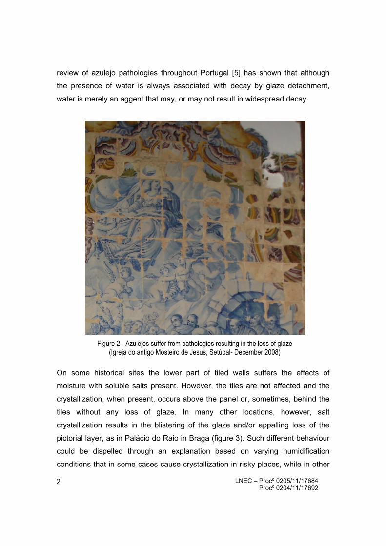
FIGURE INDEX Figure 1 – Azulejos are a distinctive mark of Portuguese culture (Igreja do Terço, Barcelos) 1Figure 2 – Azulejos suffer from pathologies resulting in the loss of glaze
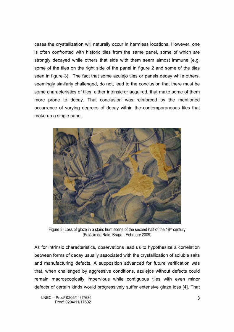
(Igreja do antigo Mosteiro de Jesus, Setúbal - December 2008) 2Figure 3 – Loss of glaze in a stairs hunt scene of the second half of the 18th century
(Palácio do Raio, Braga - February 2009) 3Figure 4 – Cracking systems are often confusing with optical imaging ... 6Figure 5 – LNEC’s JEOL JSM-6400 7Figure 6 – A selection of Types I and II samples for study through artificial ageing tests 8Figure 7 – A pattern of crazing highlighted by efflorescence 9Figure 8 – BSE images of an azulejo cross section showing crazing cracks propagating
vertically into the clay body 11Figure 9 – BSE view of a crazing crack propagating in the glaze/biscuit interface
and close-up X-ray maps of Carbon and Silicon 12
Figure 10 – SEI images of sample Az02/11 showing crazing cracks propagating down into the biscuit with side branching and sideways into the glaze/biscuit interface 12
Figure 11– Efflorescence in a crazed tile (Coimbra Old University- photographed 2008) 13Figure 12 – Delamination of the glaze from the biscuit in a severe case of Type II crazing 14Figure 13 – Delamination of the crazed glaze from the biscuit after cycles of accelerated ageing 15Figure 14 – One step of the graphic result of a numerical model of a propagating glaze delamination 16Figure 15- SEM (BSE) images showing the glaze delaminated by shivering depicting
the characteristic wavy morphology its propagation almost exclusively through the ceramic body 17
Figure 16 – A typical decay morphology probably indicating that the tiles were initially shivered to the edges (Viseu Cathedral- May 2010) 18
Figure 17 – 17th century tile with a round lacuna inside the glaze area 18Figure 18 – Glaze delamination over a biscuit recess that does not reach the edges 19Figure 19 – A pin-hole through the glaze provides a direct evaporation route
from the ceramic body to the exterior 19
Figure 20 – Typical glaze loss through efflorescence under a shivering delamination (the position of the evaporation pin-hole is imprinted on the ceramic body) 20
Figure 21 – 3D optical surface profile of a sample after two cycles of accelerated ageing. The raised area of delaminated glaze and its breakage are evident.
21
Figure 22 – Evolution until breakage of a simulated glaze delamination with a through pore 21Figure 23 – Glaze bubbles in an azulejo (BSE) 22Figure 24 – A tile affected with a pathology that stains the white majolica compared to a sound tile 23Figure 25 – Microscopic images of a stained tile seen from the top and in section 23Figure 26 – Those bubbles accessible from the surface can demonstrably be filled from there 24


LNEC – Procº 0205/11/17684 Procº 0204/11/17692
1
A RESEARCH ON MANUFACTURING DEFECTS
AND DECAY BY GLAZE LOSS IN PORTUGUESE AZULEJOS
1- AN INTRODUCTION TO THE THEME
Figure 1 - Azulejos are a distinctive mark of Portuguese culture (Igreja do Terço, Barcelos)
Portuguese glazed ceramic tiles - azulejos - are a distinctive mark of Portuguese
culture (figure 1). The conservation of the Baroque churches, palaces and even
gardens calls for the conservation of the azulejo panels that decorate them.
However they suffer from several pathologies that result in the loss of the glaze
and, with it, of the pictorial layer (figure 2).
The available literature about decay of historic azulejos [1,2,3] consistently points
to the crystalization of soluble salts as a major cause of glaze detachment. But a
LNEC – Procº 0205/11/17684 Procº 0204/11/17692
2
review of azulejo pathologies throughout Portugal [5] has shown that although
the presence of water is always associated with decay by glaze detachment,
water is merely an aggent that may, or may not result in widespread decay.
Figure 2 - Azulejos suffer from pathologies resulting in the loss of glaze (Igreja do antigo Mosteiro de Jesus, Setúbal- December 2008)
On some historical sites the lower part of tiled walls suffers the effects of
moisture with soluble salts present. However, the tiles are not affected and the
crystallization, when present, occurs above the panel or, sometimes, behind the
tiles without any loss of glaze. In many other locations, however, salt
crystallization results in the blistering of the glaze and/or appalling loss of the
pictorial layer, as in Palácio do Raio in Braga (figure 3). Such different behaviour
could be dispelled through an explanation based on varying humidification
conditions that in some cases cause crystallization in risky places, while in other
LNEC – Procº 0205/11/17684 Procº 0204/11/17692
3
cases the crystallization will naturally occur in harmless locations. However, one
is often confronted with historic tiles from the same panel, some of which are
strongly decayed while others that side with them seem almost immune (e.g.
some of the tiles on the right side of the panel in figure 2 and some of the tiles
seen in figure 3). The fact that some azulejo tiles or panels decay while others,
seemingly similarly challenged, do not, lead to the conclusion that there must be
some characteristics of tiles, either intrinsic or acquired, that make some of them
more prone to decay. That conclusion was reinforced by the mentioned
occurrence of varying degrees of decay within the contemporaneous tiles that
make up a single panel.
Figure 3- Loss of glaze in a stairs hunt scene of the second half of the 18th century (Palácio do Raio, Braga - February 2009)
As for intrinsic characteristics, observations lead us to hypothesize a correlation
between forms of decay usually associated with the crystallization of soluble salts
and manufacturing defects. A supposition advanced for future verification was
that, when challenged by aggressive conditions, azulejos without defects could
remain macroscopically impervious while contiguous tiles with even minor
defects of certain kinds would progressively suffer extensive glaze loss [4]. That

LNEC – Procº 0205/11/17684 Procº 0204/11/17692
4
condition could arise even when the influence of soluble salts was seemingly
negligible. Hence the importance of a clear understanding of the cracking
patterns and other defects that is the main theme of the present research report.
As for acquired characteristics, observations also lead us to suspect that a
physical damage, as for instance the breakage resulting from an impact or the
insertion of a nail, could soften a spot from where decay would progress that
would not have occurred otherwise. We call this “the first damage hypothesis”
and it explains why often tiles decay from the edges by twos, threes and fours, as
in figure 3. In this particular case, a first damage could result from the
interference between tiles caused by hydric expansion. The propagation of decay
from a damaged area is being studied presently and will be the subject of a future
publication.
LNEC – Procº 0205/11/17684 Procº 0204/11/17692
5
2- METHOD
During 2009-2010 inspection visits were made to a number of monuments and
sites with relevant sets of 17th and 18th centuries azulejos [5]. The visits aimed at
collecting data on the degradation of tiles as well as on the prevailing
environmental conditions that might have caused the onset of decay. The sites
ranged from South Portugal (Alentejo) to the Northern Province of Minho.
Degradation forms were classified as presumably resulting from damage caused
by human action or mechanical interference of any form (that is, decay that would
not have occurred in the existing conditions, if some form of interference with the
tiles had not taken place), and decay that presumably followed manufacturing
defects (that is, decay that given the existing conditions would necessarily occur
because the tiles had an in-built weakness but would not if that weakness was
not present). This last sort of decay was considered of interest to correlate with
manufacturing defects detected by microscopic observation.
The method comprised microscopic observation of defects (both optical and
electronic) and the simulation of decay through ageing tests with salt
crystallization.
2.1- Observation by Optical Microscopy (OM)
Tile defects were studied by OM using both a binocular microscope Meiji- EMZ-
TR and a petrographic microscope Zeiss Axioplan MC-100. However, it must be
borne in mind that very thin cracking is not always apparent. The biscuits of early
Portuguese tiles are usually of a very light colour, so as to avoid impairing the
whiteness of the majolica, and thus the exact boundary between glaze and
biscuit may be difficult to pinpoint by OM while the true extension and path of thin
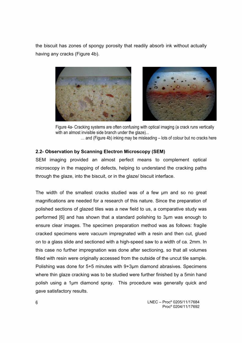
cracks is not easily disclosed (figure 4a) particularly when they propagate
horizontally in the glaze-biscuit interface.
The use of penetrating inks may be helpful but may also be problematic because
LNEC – Procº 0205/11/17684 Procº 0204/11/17692
6
the biscuit has zones of spongy porosity that readily absorb ink without actually
having any cracks (Figure 4b).
Figure 4a- Cracking systems are often confusing with optical imaging (a crack runs vertically with an almost invisible side branch under the glaze)...
… and (Figure 4b) inking may be misleading – lots of colour but no cracks here
2.2- Observation by Scanning Electron Microscopy (SEM)
SEM imaging provided an almost perfect means to complement optical
microscopy in the mapping of defects, helping to understand the cracking paths
through the glaze, into the biscuit, or in the glaze/ biscuit interface.
The width of the smallest cracks studied was of a few μm and so no great
magnifications are needed for a research of this nature. Since the preparation of
polished sections of glazed tiles was a new field to us, a comparative study was
performed [6] and has shown that a standard polishing to 3μm was enough to
ensure clear images. The specimen preparation method was as follows: fragile
cracked specimens were vacuum impregnated with a resin and then cut, glued
on to a glass slide and sectioned with a high-speed saw to a width of ca. 2mm. In
this case no further impregnation was done after sectioning, so that all volumes
filled with resin were originally accessed from the outside of the uncut tile sample.
Polishing was done for 5+5 minutes with 9+3μm diamond abrasives. Specimens
where thin glaze cracking was to be studied were further finished by a 5min hand
polish using a 1μm diamond spray. This procedure was generally quick and
gave satisfactory results.

LNEC – Procº 0205/11/17684 Procº 0204/11/17692
7
The SEM used was LNEC’s JEOL JSM-6400 with a X-ray EDS detector INCA
X’sight from Oxford Instruments (figure 5).
Backscattered electrons (BSE) imaging was usually preferred because the lead-
rich glaze is enhanced, ensuring clear boundaries. The samples were coated
with Au/Pd (80/20) so that Carbon was only present in the sample and in the
filling resin. The resin-filled voids show as very dark areas in the image and the
use of EDS (X-ray mapping of C) can confirm that these are indeed filled with
organic resin and are thus accessible from the surface of the glaze or from the
side of the glaze-biscuit interface through paths that may, or may not, appear in
the final sections. EDS X-ray mapping of Silicon was also used because that
element is only absent from the voids and the resin-filled cracks.
Figure 5- LNEC’s JEOL JSM-6400
2.3- Ageing tests
Simulated ageing tests were performed through wet/dry cycles. A complete
report on these tests and their results will be given in another medium, but a
synopsis is necessary to this report.
Two sorts of samples were prepared for test: Type I- small ca. 35-45 sq.cm
pieces were cut from azulejos - these were chosen so that the glaze area would
include the defect to be studied; and Type II- squares of biscuit of approximately
50 sq.cm over which 0.74 mm thick glass was glued with epoxy resin in a way
LNEC – Procº 0205/11/17684 Procº 0204/11/17692
8
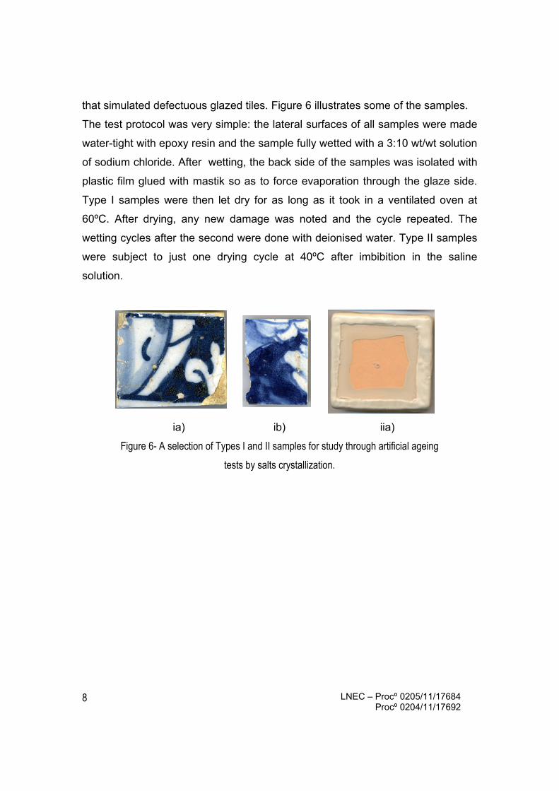
that simulated defectuous glazed tiles. Figure 6 illustrates some of the samples.
The test protocol was very simple: the lateral surfaces of all samples were made
water-tight with epoxy resin and the sample fully wetted with a 3:10 wt/wt solution
of sodium chloride. After wetting, the back side of the samples was isolated with
plastic film glued with mastik so as to force evaporation through the glaze side.
Type I samples were then let dry for as long as it took in a ventilated oven at
60ºC. After drying, any new damage was noted and the cycle repeated. The
wetting cycles after the second were done with deionised water. Type II samples
were subject to just one drying cycle at 40ºC after imbibition in the saline
solution.
ia) ib) iia)
Figure 6- A selection of Types I and II samples for study through artificial ageing
tests by salts crystallization.
LNEC – Procº 0205/11/17684 Procº 0204/11/17692
9
3- CRAZING
3.1- Microscopic study
When a tile cools after the second firing and if the thermal expansion coefficients
of the glaze and the biscuit are not finely tuned, the glaze top may contract
substantially more than the biscuit. Then the ceramic body exerts through the
interface a homogeneous traction on the glaze. Glass cannot respond elastically
and will crack. The fissures propagate sideways, until a crack meets another at
an app 90º angle, and vertically until the tension is relieved [7]. This situation
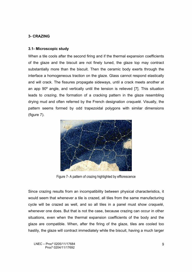
leads to crazing, the formation of a cracking pattern in the glaze resembling
drying mud and often referred by the French designation craquelé. Visually, the
pattern seems formed by odd trapezoidal polygons with similar dimensions
(figure 7).
Figure 7- A pattern of crazing highlighted by efflorescence
Since crazing results from an incompatibility between physical characteristics, it
would seem that whenever a tile is crazed, all tiles from the same manufacturing
cycle will be crazed as well, and so all tiles in a panel must show craquelé,
whenever one does. But that is not the case, because crazing can occur in other
situations, even when the thermal expansion coefficients of the body and the
glaze are compatible. When, after the firing of the glaze, tiles are cooled too
hastily, the glaze will contract immediately while the biscuit, having a much larger

LNEC – Procº 0205/11/17684 Procº 0204/11/17692
10
thermal mass, will have a delayed response. And so, crazing may occur during
cooling even though it might not have occurred had the cooling been slower. For
that reason, some tiles that cooled faster may be crazed, while others are not.
There can also be a delayed crazing caused by moisture intake. When tiles are
wetted, and particularly when tiles that are applied to the walls suffer cycles of
wetting and drying, the biscuit will expand due to the intake of water, but the
glaze will not take any appreciable amount of water and thus the body will apply
on the glaze a homogeneous traction that may result in a crazing pattern.
Although in this case crazing occurs months, years or even decades after
manufacturing, it may still be considered as a result of the manufacturing process
because, as was recognized since the phenomena involved were understood, a
good fit is one where in normal conditions the glaze is in slight compression so
that the wetting of the biscuit will result in a state nearing a null interfacial stress.
Crazing is, thus, a widespread phenomenon with several possible remote causes
but only one apparent result: the formation of the characteristic tile-pattern.
However a microscopic study reveals the occurrence of two very different cases:
one where the cracks cross the glaze-biscuit interface vertically and propagate
forward into the body; and one where once the interface is reached the cracks
change direction and propagate transversally through the interface. There are
also cases of mixed propagation where the stresses are relieved through both a
vertical and an interfacial propagation.
On another medium our group disclosed the results of a simulation of azulejo
crazing [4] with a numerical model based on a Delft lattice [8] on a MATLAB
environment. The simulation predicted that, when the bond between the glaze
and the biscuit is considerably stronger than the cohesion of the biscuit itself (as
is often the case) the cracks originating in the glaze will initially propagate
vertically into the biscuit, eventually with side branches inside the ceramic body in

LNEC – Procº 0205/11/17684 Procº 0204/11/17692
11
bad cases of crazing. When, however, the bond between glaze and biscuit is
relatively lower than the cohesion of the biscuit, the cracking will follow the path
of less resistance under the glaze and detach it locally from the biscuit. The
SEM-based research confirmed the predictions and further gave evidence of the
paths followed and of cases where both kinds of propagation co-exist in the same
tile.
Figure 8 shows the path of vertical propagation of individual crazing cracks in one
of our samples. This is the simplest case, where cracks propagate down for a
length that does not usually exceed double the glaze width, without branching.
We named these: Type I crazing cracks.
Figure 8- BSE images of an azulejo cross section showing crazing cracks propagating vertically into the ceramic body (sample Az02/07)
Figure 9a shows crazing in a case where the cracks propagate into the biscuit
but mostly in the glaze/biscuit interface (the slide was prepared from a sample of
the tile illustrated in figure 7). The SEM images clearly show the vertical
development of the crack that distorted a gas bubble, propagating sideways
under the glaze. Using the fact that the impregnation with resin filled the
accessible voids, figure 9b depicts an X-ray map of Carbon, marking positively
the path into the biscuit, and figure 9c a similar map of Silicon, which is a
negative marker of voids and often shows the cracking patterns in a more clear
way. We named these: Type II crazing cracks.

LNEC – Procº 0205/11/17684 Procº 0204/11/17692
12
Figure 9a- BSE view of a crazing crack propagating in the glaze/biscuit interface and close-up X-ray maps of Carbon (9b) and Silicon (9c)- sample Az02/06
Not all tiles craze down, either into the biscuit, or else sideways under the glaze.
In some, both paths offer routes of similar resistance and thus cracks propagate
both down and sideways. Figure 10 illustrates two views taken on a single tile
illustrating the double path.
Figure 10 – SEI images of sample Az02/11 showing crazing cracks propagating down into the biscuit with side branching (9a) and sideways into the glaze/biscuit interface (9b)
In the particular case of the tile illustrated in figure 10, the biscuit had a confusing
BSE image and so it had to be polished for 5+5 minutes with 1μm diamond grit
and secondary electron imaging (SEI) had to be used to achieve an acceptable
result. This particular tile was ultimately seen to have a cracking system that
LNEC – Procº 0205/11/17684 Procº 0204/11/17692
13
actually spanned its whole width at some spots and was widely colonized by
filamentous fungi. The cases of mixed propagation like this one must be
considered as Type II crazing because, as shall be shown next, that is the type
resulting in a more immediate risk to the preservation of the tile.
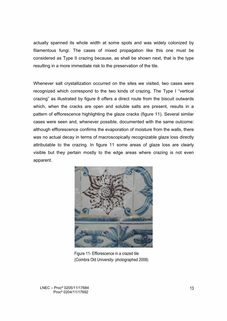
Whenever salt crystallization occurred on the sites we visited, two cases were
recognized which correspond to the two kinds of crazing. The Type I “vertical
crazing” as illustrated by figure 8 offers a direct route from the biscuit outwards
which, when the cracks are open and soluble salts are present, results in a
pattern of efflorescence highlighting the glaze cracks (figure 11). Several similar
cases were seen and, whenever possible, documented with the same outcome:
although efflorescence confirms the evaporation of moisture from the walls, there
was no actual decay in terms of macroscopically recognizable glaze loss directly
attributable to the crazing. In figure 11 some areas of glaze loss are clearly
visible but they pertain mostly to the edge areas where crazing is not even
apparent.
Figure 11- Efflorescence in a crazed tile (Coimbra Old University- photographed 2008)

LNEC – Procº 0205/11/17684 Procº 0204/11/17692
14
Type II crazing that propagates horizontally is a different matter altogether. Since
it runs into the glaze-biscuit interface, it causes a partial delamination of the
mosaic patches of glaze. And so Type II crazing as illustrated in figure 9
originates a mosaic of “glaze islands” that are already partly detached from the
biscuit. The hidden crystallization of salts or any other physical process causing
shear stresses in the interface (moisture or thermal cycles, or maybe even
vibration) may conceivably contribute to the propagation of damage resulting in a
patchy mosaic-like detachment (figure 12). In this form of decay, a clean
relatively smooth biscuit surface results with a characteristic polyhedral glaze
boundary resulting from the detachment of full crazing “islands” or parts thereof.
Often this sort of crazing is also highlighted by efflorescence, particularly
whenever the loss of glaze is yet minimal, but it will likely, in time, lead to glaze
detachments and thus calls for remedial measures without which all the glaze
may eventually be lost.
Figure 12- Delamination of the glaze from the biscuit in a severe case of Type II crazing (Igreja dos Terceiros de S. Francisco, Viseu- May 2010)
3.2- Ageing tests
We simulated the decay of tiles with crazing in the laboratory through accelerated
ageing tests with salt solutions, as described in Chapter 2.3, obtaining the
LNEC – Procº 0205/11/17684 Procº 0204/11/17692
15
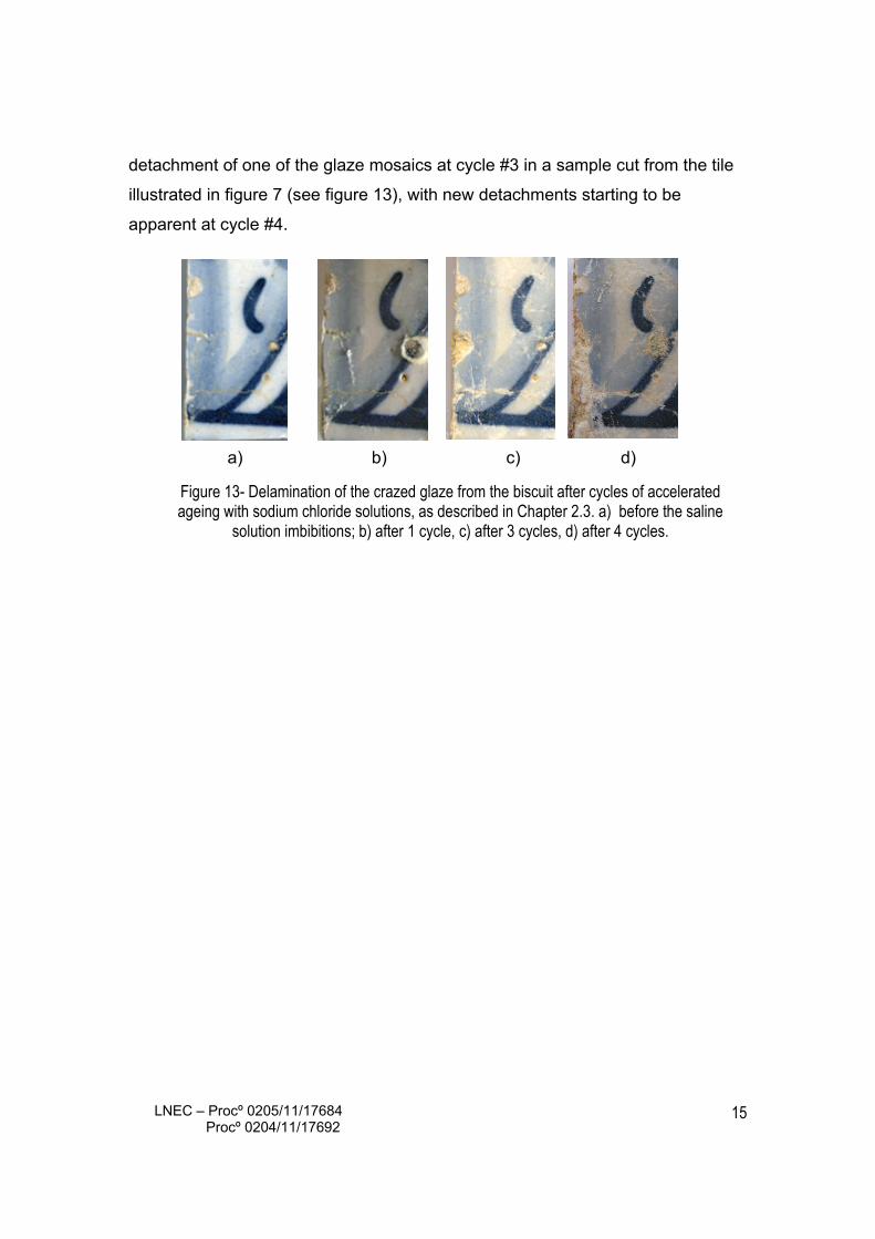
detachment of one of the glaze mosaics at cycle #3 in a sample cut from the tile
illustrated in figure 7 (see figure 13), with new detachments starting to be
apparent at cycle #4.
a) b) c) d)
Figure 13- Delamination of the crazed glaze from the biscuit after cycles of accelerated ageing with sodium chloride solutions, as described in Chapter 2.3. a) before the saline
solution imbibitions; b) after 1 cycle, c) after 3 cycles, d) after 4 cycles.
LNEC – Procº 0205/11/17684 Procº 0204/11/17692
16
4- GLAZE DELAMINATION BY SHIVERING
4.1- An introduction to shivering
A less known but potentially more noxious manufacturing defect than crazing is
shivering, which stems from the opposite situation: the thermal expansion
coefficient of the glaze is not tuned to that of the biscuit in a way that during the
cooling phase, after the second firing, the ceramic body contracts considerably
more than the glaze. Due to the resulting compression tensions, the glaze may
suffer small nicks on the edges or detach from the biscuit (glaze delamination).
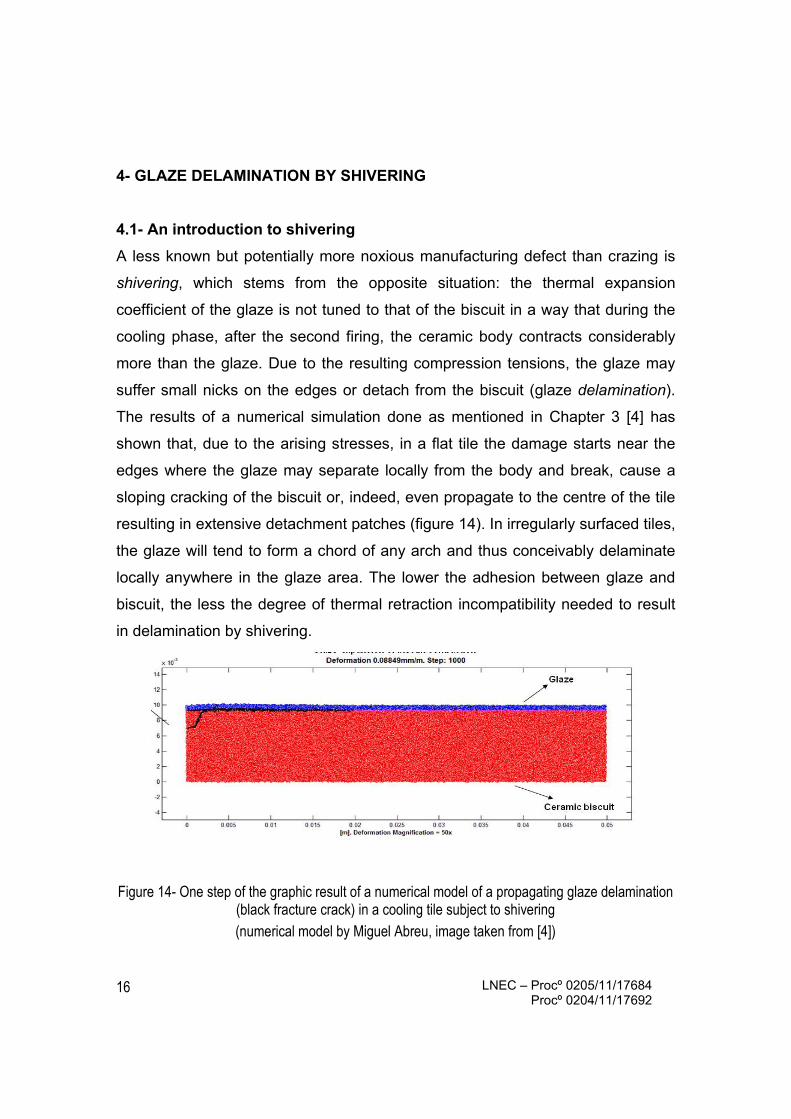
The results of a numerical simulation done as mentioned in Chapter 3 [4] has
shown that, due to the arising stresses, in a flat tile the damage starts near the
edges where the glaze may separate locally from the body and break, cause a
sloping cracking of the biscuit or, indeed, even propagate to the centre of the tile
resulting in extensive detachment patches (figure 14). In irregularly surfaced tiles,
the glaze will tend to form a chord of any arch and thus conceivably delaminate
locally anywhere in the glaze area. The lower the adhesion between glaze and
biscuit, the less the degree of thermal retraction incompatibility needed to result
in delamination by shivering.
Figure 14- One step of the graphic result of a numerical model of a propagating glaze delamination (black fracture crack) in a cooling tile subject to shivering (numerical model by Miguel Abreu, image taken from [4])
LNEC – Procº 0205/11/17684 Procº 0204/11/17692
17
4.2- Microscopic study
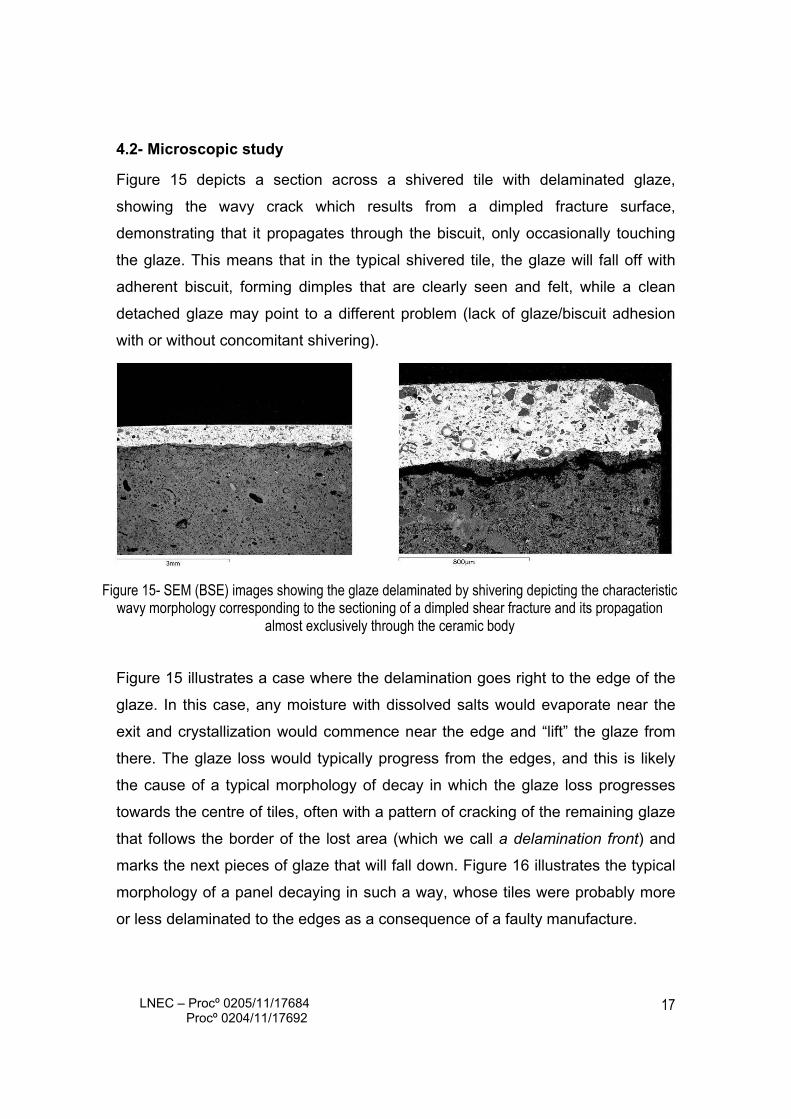
Figure 15 depicts a section across a shivered tile with delaminated glaze,
showing the wavy crack which results from a dimpled fracture surface,
demonstrating that it propagates through the biscuit, only occasionally touching
the glaze. This means that in the typical shivered tile, the glaze will fall off with
adherent biscuit, forming dimples that are clearly seen and felt, while a clean
detached glaze may point to a different problem (lack of glaze/biscuit adhesion
with or without concomitant shivering).
Figure 15- SEM (BSE) images showing the glaze delaminated by shivering depicting the characteristic wavy morphology corresponding to the sectioning of a dimpled shear fracture and its propagation
almost exclusively through the ceramic body
Figure 15 illustrates a case where the delamination goes right to the edge of the
glaze. In this case, any moisture with dissolved salts would evaporate near the
exit and crystallization would commence near the edge and “lift” the glaze from
there. The glaze loss would typically progress from the edges, and this is likely
the cause of a typical morphology of decay in which the glaze loss progresses
towards the centre of tiles, often with a pattern of cracking of the remaining glaze
that follows the border of the lost area (which we call a delamination front) and
marks the next pieces of glaze that will fall down. Figure 16 illustrates the typical
morphology of a panel decaying in such a way, whose tiles were probably more
or less delaminated to the edges as a consequence of a faulty manufacture.
LNEC – Procº 0205/11/17684 Procº 0204/11/17692
18
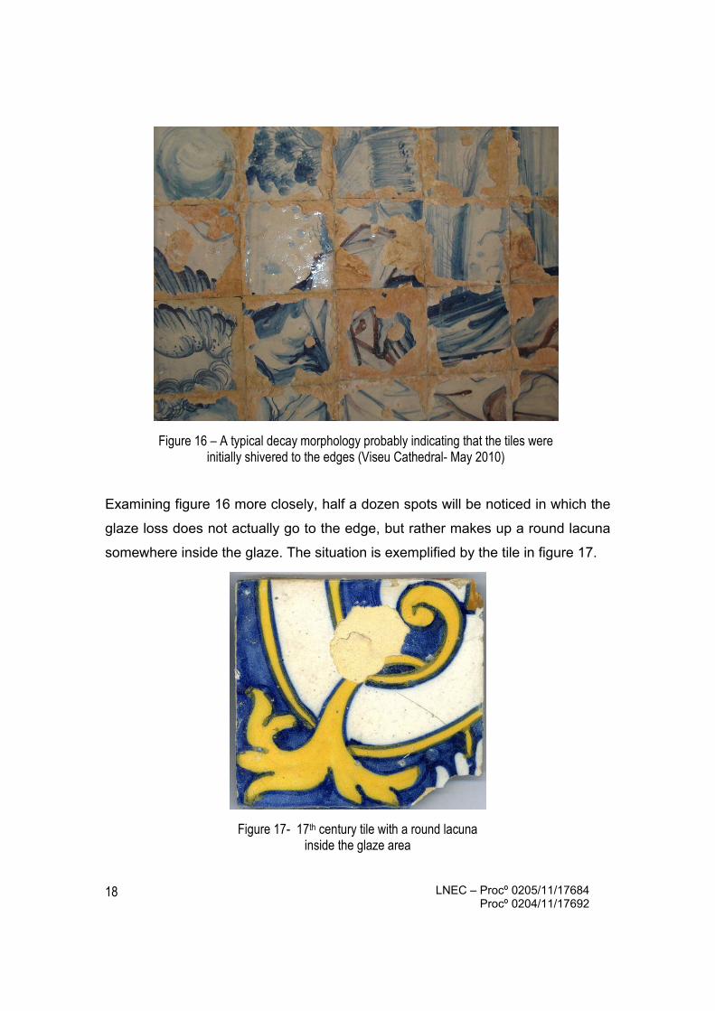
Figure 16 – A typical decay morphology probably indicating that the tiles were initially shivered to the edges (Viseu Cathedral- May 2010)
Examining figure 16 more closely, half a dozen spots will be noticed in which the
glaze loss does not actually go to the edge, but rather makes up a round lacuna
somewhere inside the glaze. The situation is exemplified by the tile in figure 17.
Figure 17- 17th century tile with a round lacuna inside the glaze area

LNEC – Procº 0205/11/17684 Procº 0204/11/17692
19
This case corresponds to shivering delaminations which only affect an area
inside the glaze and do not go to the edge, as exemplified by the longitudinal cut
of figure 18. It is an important cause of decay, as will be seen next.
Figure 18a- Part of a longitudinal cut in a shivered tile showing a glaze delamination over a recess that does not reach the edges (marked by a grey line); 18b- detail under the optical microscope
The situation illustrated in figure 18, though alarming, may go unnoticed for
decades or even centuries if the azulejo panels are on dry walls. But when the
walls are wet, the biscuit will absorb moisture and expand, while the glaze does
not. When the expansion of the ceramic body overcomes any residual
compression that the glaze may retain, the glaze will be put in traction and
eventually crack. When the biscuit dries and contracts, the glaze will lift.
Eventually pieces will break off.
When the glaze has pin-holes (figure 19) these provide an evaporative route to
the water wetting the ceramic body. If that water contains soluble salts, as it in
general does, crystallization will occur under the pin-hole, in the empty space
between the biscuit and the glaze. The agglomeration of salt will eventually start
lifting the glaze, forming a bubble that, in time, breaks resulting in an immediate
roundish lacuna that may have an area exceeding 1 sq.cm. Whenever
delaminated glaze remains at its boundaries, the process will proceed and the
lacuna will slowly widen until most of the glaze is lost (figure 20a, b).
Figure 19- A pin-hole through the glaze provides a direct evaporation route from the ceramic body to the exterior

LNEC – Procº 0205/11/17684 Procº 0204/11/17692
20
As said before, such cases need the previous occurrence of shivering
delamination and a pin-hole through the glaze. After the lacuna is formed, the
imprint of the original pin-hole can sometimes be recognized on the remaining
biscuit, often with rings of salt crystallization around it, giving testimony of the
process that lead to it (see, for instance, figure 20 a).
Figure 20a- Typical glaze loss through efflorescence under a shivering delamination (the position of the evaporation pin-hole is imprinted on the ceramic body) and (20b) grazing view of another
area of the same panel making the delamination apparent (Madre de Deus Convent, Lisbon- July 2009)
4.3- Ageing tests
Shivering is an insidious manufacturing defect that, given the proper conditions,
may lead to extensive glaze losses in a relatively short lapse of time and so this
case, quite common but, to our knowledge, misunderstood and as yet
undescribed in scientific literature until now as a source of decay of azulejos, has
been of considerable interest to us. We simulated this phenomenon in the
laboratory through accelerated ageing tests with salt solutions, both on the
naturally delaminated tile shown in figure 18a and in simulated tiles made from
thin sheets of glass with pin-holes across that were glued on their periphery to
ceramic bodies (as described in chapter 2.3 and shown in figure 6). On both
cases the bubbling behaviour was observed, eventually leading to the loss of
LNEC – Procº 0205/11/17684 Procº 0204/11/17692
21
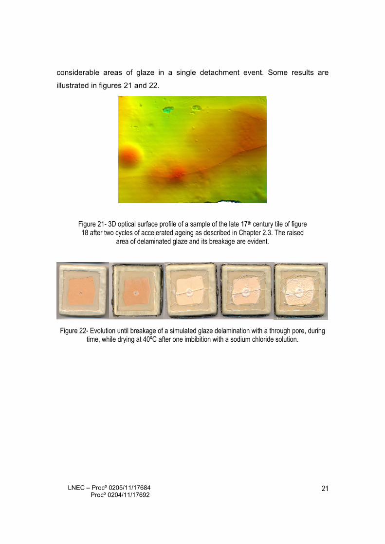
considerable areas of glaze in a single detachment event. Some results are
illustrated in figures 21 and 22.
Figure 21- 3D optical surface profile of a sample of the late 17th century tile of figure 18 after two cycles of accelerated ageing as described in Chapter 2.3. The raised
area of delaminated glaze and its breakage are evident.
Figure 22- Evolution until breakage of a simulated glaze delamination with a through pore, during time, while drying at 40ºC after one imbibition with a sodium chloride solution.
LNEC – Procº 0205/11/17684 Procº 0204/11/17692
22
5- FERRUGINOUS GLAZE STAINING
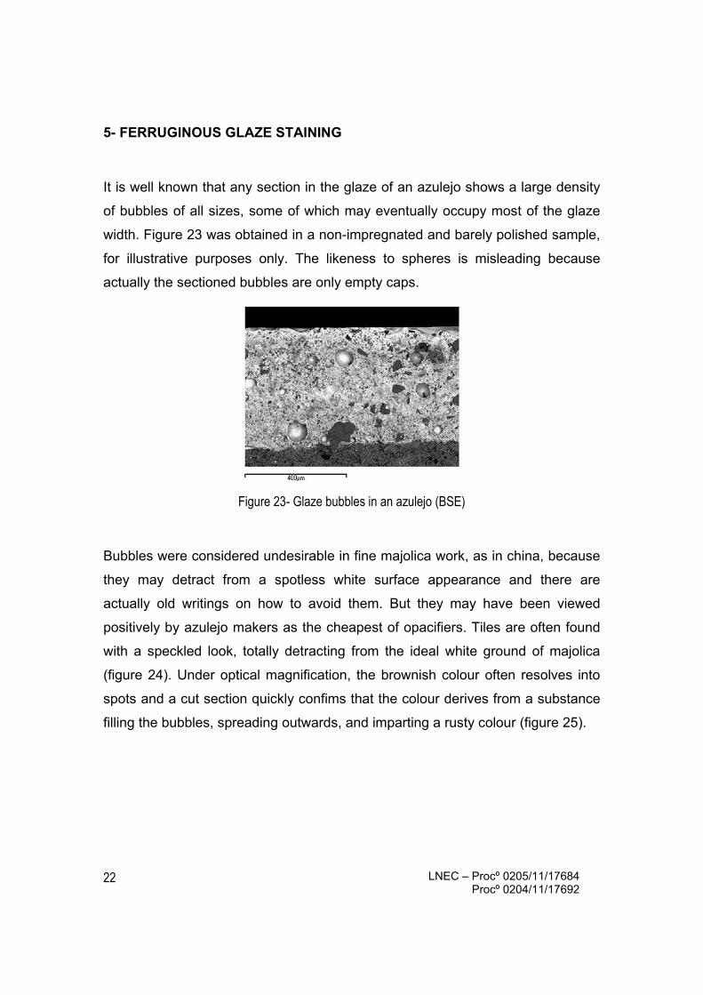
It is well known that any section in the glaze of an azulejo shows a large density
of bubbles of all sizes, some of which may eventually occupy most of the glaze
width. Figure 23 was obtained in a non-impregnated and barely polished sample,
for illustrative purposes only. The likeness to spheres is misleading because
actually the sectioned bubbles are only empty caps.
Figure 23- Glaze bubbles in an azulejo (BSE)
Bubbles were considered undesirable in fine majolica work, as in china, because
they may detract from a spotless white surface appearance and there are
actually old writings on how to avoid them. But they may have been viewed
positively by azulejo makers as the cheapest of opacifiers. Tiles are often found
with a speckled look, totally detracting from the ideal white ground of majolica
(figure 24). Under optical magnification, the brownish colour often resolves into
spots and a cut section quickly confims that the colour derives from a substance
filling the bubbles, spreading outwards, and imparting a rusty colour (figure 25).
LNEC – Procº 0205/11/17684 Procº 0204/11/17692
23
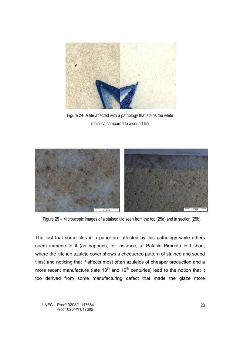
Figure 24- A tile affected with a pathology that stains the white
majolica compared to a sound tile
Figure 25 – Microscopic images of a stained tile seen from the top (25a) and in section (25b)
The fact that some tiles in a panel are affected by this pathology while others
seem immune to it (as happens, for instance, at Palacio Pimenta in Lisbon,
where the kitchen azulejo cover shows a chequered pattern of stained and sound
tiles) and noticing that if affects most often azulejos of cheaper production and a
more recent manufacture (late 18th and 19th centuries) lead to the notion that it
too derived from some manufacturing defect that made the glaze more

LNEC – Procº 0205/11/17684 Procº 0204/11/17692
24
permeable than is usually the case and afforded paths from the exterior to the
interior of the glaze bubbles.
A simple check was performed on samples prepared for SEM work that were
purposedly not re-impregnated after cutting. Then, any bubbles filled with resin
have to have been filled from the exterior, even if the entry path is not evident in
the final section used for viewing. Figure 26a depicts an example in secondary
electrons imaging (SEI) in which the resin-filled bubbles are conspicuously black.
Figure 26b shows the same in the so-called topographic mode (BSE-TOP), in
which those resin-filled bubbles come out flat contrarily to those that are not
connected to the glaze surface and show as caps. Finally figure 26c depicts the
X-ray map of Carbon in another area of the same slide in which three bubbles
near the glaze/biscuit interface are seen to be filled with resin and thus prove to
be connected to the surface of the tile.
Figure 26- Those bubbles accessible from the surface (and potentially stained with a brownish inclusion) can demonstrably be filled from the surface with impregnating resin and clearly distinguished
in SEI (left), BSE-TOP mode (center) and in an X-ray map of Carbon of another area of Sample Az02/03

LNEC – Procº 0205/11/17684 Procº 0204/11/17692
25
6- CONCLUDING REMARKS
Although a wall wet with infiltrations carrying soluble salts is the near cause of
decay of many historic Portuguese azulejo panels, there are insidious far causes
stemming from an array of manufacturing defects that were, so to say, built-in
and subsequently lay in waiting for conditions favourable to the onset of decay.
The understanding of this fact is of the utmost importance for conservation work.
It is not enough to reintegrate lacunae: when dangerous tile defects are present
they must also be addressed, even when hidden, for a restoration to be durable.
If preventive interventions are considered, it would be of capital importance to
detect those defects that render tiles fragile so as to make it possible to apply
corrective measures to ensure, as far as technologically possible, that the
concurrence of factors leading to decay is avoided at all times for the sake of
preservation of the heritage values.
The survey of decay forms on relevant heritage sites together with the
microscopic study of manufacturing defects on Portuguese azulejos and
laboratory simulations allowed relating decay with some defects and
understanding how a situation originating centuries before may, much later, lead
to decay and often total loss of the painted glazed layer when certain adverse
conditions occur.
The knowledge achieved is now being used on a larger research programme to
simulate the several situations in the laboratory, where the parameters may be
controlled, aiming to confirm hypotheses and improve the scientific knowledge
about azulejos and hopefully contributing, in the near future, to the full
understanding of the onset of decay. This will foster the development of counter
measures allowing to intervene on the decaying panels, as well as on those at
risk, to help ensure the full longevity that glazed tiles were supposed to enjoy.
LNEC – Procº 0205/11/17684 Procº 0204/11/17692
26
Acknowledgements
SEM / EDS operator : Ana Paula Menezes
Preparation of slides with polished sections: Luís Figueiredo Nunes
Bibliographic references 1 ESTEVES, L. - Os grandes problemas da conservação e restauro do azulejo. Revista Azulejo 8/11, Museu Nacional do Azulejo, Lisbon, 2003, pp 21-38. 2 FIGUEIREDO, M.O- Estudo e caracterização de materiais cerâmicos culturais: o paradigma azulejar., 2003, ibid pp 11-19. 3 BORGES, C. et al. - Monitoring the removal of soluble salts from ancient tiles by ion chromatography. J. of Chromatography A, 770, 1997, pp 195-201. 4 MIMOSO, J-M et al. – Decay of historic azulejos in Portugal: an assessment of research needs, in Proc. Int. Sem. Conservation of glazed ceramic tiles - research and practice, LNEC, Lisbon, April 15-16, 2009. 5 MIMOSO, J-M – Levantamento em obra de patologias em azulejos históricos- visitas realizadas em 2009-2010”, LNEC Research report 22 / 2010 DM, Lisbon, January 2011 6 NUNES, L. – Preparação de superfícies polidas em materiais porosos, Nota Técnica 06/2011 DM, LNEC, 2011. 7 YOSHIKAWA, T. - Study on Crack Propagating and Its Pattern in Powder Solution Due to Desiccating Shrinkage. Proc.31st Int. Conf. on Computers and Industrial Eng, 2000. 8 SCHLANGEN, E. & GARBOCZI, E. - Fracture simulation of concrete using lattice models:
computational aspects in Eng. Fracture Mech. Vol.57 nº 2/3, 1997, pp319-332.
Lisboa, Janeiro de 2011


Divisão de Divulgação Científica e Técnica - LNEC