Embed Size (px)
Citation preview
Appendix C SCHEDULE 1 Page 1 of 37
CT1204G021
A. REQUIREMENTS AND SPECIFICATIONS FOR PREVENTIVE MAINTENANCE
1 OBJECTIVES OF PREVENTIVE MAINTENANCE 2 TOOLS & SPARE PARTS
3 SCOPE OF WORK 4 WEEKLY & MONTHLY STATISTICAL & MANAGEMENT REPORT
APPENDIX A EQUIPMENT LIST APPENDIX B
PREVENTIVE MAINTENANCE CHECKLIST INDEX & EXAMPLE OF PREVENTIVE MAINTENANCE CHECKLIST
APPENDIX C EXAMPLE OF A MONTHLY PREVENTIVE MAINTENANCE SCHEDULE APPENDIX D WEEKLY & MONTHLY STATISTICAL & MANAGEMENT REPORTS B. REQUIREMENTS AND SPECIFICATIONS FOR FIRST LINE MAINTENANCE 1. GENERAL 2. OBJECTIVES OF FIRST LINE MAINTENANCE 3. SCOPE OF WORK 4. TOOLS AND SPARE PARTS 5. LIST OF EQUIPMENT

Appendix C SCHEDULE 1 Page 2 of 37
CT1204G021
C. General Requirements 1. COMPANY PROFILES 2. TENDERER PROPOSED MANPOWER STRUCTURE 3. TENDERER PROPOSED SUB-CONTRACTOR LIST 4. EXPERIENCES
5. EXIT PLAN
D. PERFORMANCE, PENALTY AND WARRANTY E. EXIT PLAN

Appendix C SCHEDULE 1 Page 3 of 37
CT1204G021
A. REQUIREMENTS AND SPECIFICATIONS FOR PREVENTIVE MAINTENANCE
1 OBJECTIVES OF PREVENTIVE MAINTENANCE 1.1 General Description 1.1.1 It is envisioned that the Contractor will provide all the necessary manpower, tools and
materials to perform all PM and repair works in AFT6. 1.1.2 Although the works will be performed during normal office hours, the Contractor will be
required to work on weekends, public holidays as well as normal office hours if required by SAS.
1.1.3 The Contractor is expected to be able to rely on the support from its workshops/factory
whenever the need arises. 1.2 Objectives 1.2.1 The Contractor is expected to achieve the following :
a) High equipment serviceability rate. b) Reduce spare parts usage. c) Maintain the equipment at a presentable state. d) Complete all minor repair and major repair of critical equipment within 24 hours
and major repairs of non-critical equipment within 36 hours. 2. SCOPE OF WORK The contractor is required to carry out preventive maintenance of the MHS equipment as
per the equipment schedule. To carry out repairs as required. The equipment shall include PLCs and replacement of
preloaded ICS client terminals SATS is ISO and OSHA certified. The contractor needs to follow all ISO 14001, 9001,
OSHA requirements and keep relevant records for inspection. 2. TOOLS & SPARE PARTS 2.1 The tools needed to carry out all jobs are to be provided by the Contractor. Borrowing of
specialised tools from SAS Maintenance can be arranged but this is subjected to availability. This cannot be used as an excuse for delay in the works that the Tenderer is required to carry out.
2.2 SAS shall purchase and issue the spare parts to the Tenderer.

Appendix C SCHEDULE 1 Page 4 of 37
CT1204G021
2.3 SAS shall first consider purchasing & using spares supplied by the Tenderer provided that the quality and prices are not higher than those from other suppliers.
2.4 The Contractor shall work closely with SAS and advise SAS’ store personnel on
components that they are expected to use. Shortage of spare parts cannot be used as an excuse for non-availability of the matchines. This will only be waived if the failure cannot actually be predicted during PM.
2.5 All part replaced must be original parts from the original manufacturer. This will only be
waived with approval from SAS. 3. WEEKLY & MONTHLY STATISTICS & MANAGEMENT REPORTS 3.1 The Contractor must provide statistical report on the 1
st day of the week reporting on the
events & work done during the previous week. Sample copies of the report are shown in Appendix D.
3.2 The Contractor must provide a monthly statistical report by the 10
th day of each month,
providing detail summary of the events & work done during the previous month. Sample is shown in Appendix D.
3.3 Detail information on the spare usage & manhours incurred for all the equipment in AFT6
must be readily accessible. Upon request, the Contractor must be able to extract the information from a computerised database.
3.4 The Contractor must also provide a detail PM schedule for the next month. The report must
also include the major components that will be changed. This will enable the store to purchase the spare parts in time for the change.
Appendix C SCHEDULE 1 Page 5 of 37
CT1204G021
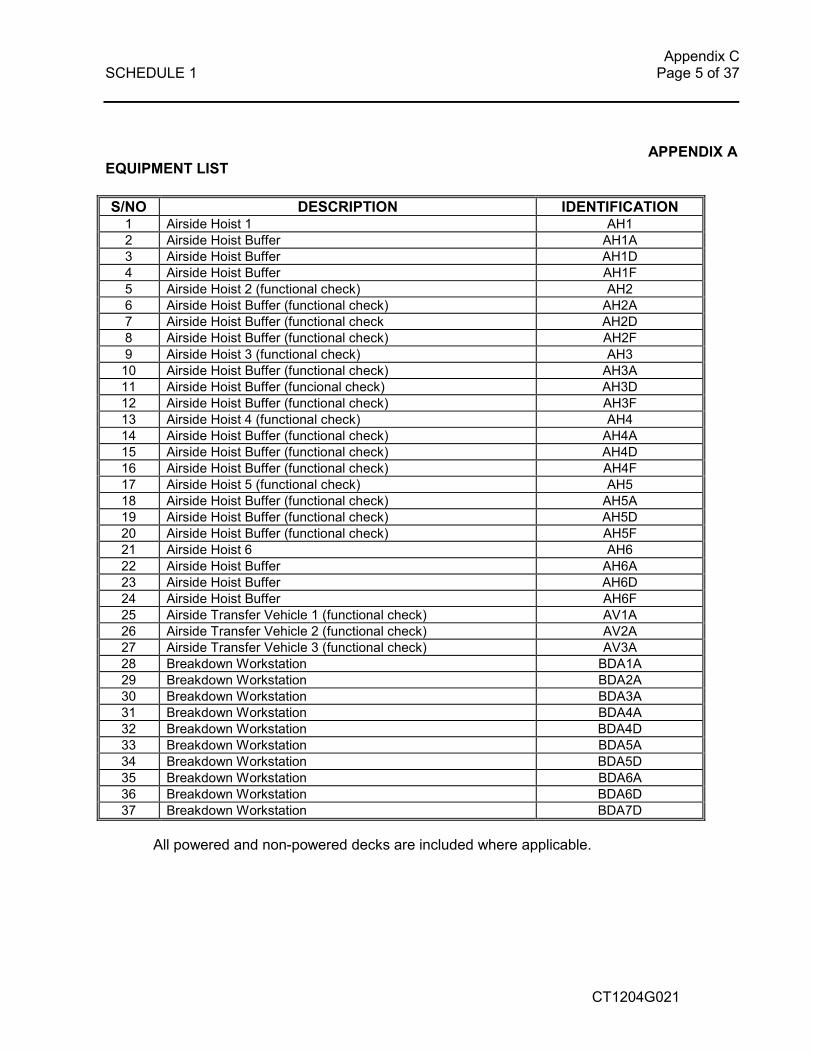
APPENDIX A EQUIPMENT LIST
S/NO DESCRIPTION IDENTIFICATION 1 Airside Hoist 1 AH1 2 Airside Hoist Buffer AH1A 3 Airside Hoist Buffer AH1D 4 Airside Hoist Buffer AH1F 5 Airside Hoist 2 (functional check) AH2 6 Airside Hoist Buffer (functional check) AH2A 7 Airside Hoist Buffer (functional check AH2D 8 Airside Hoist Buffer (functional check) AH2F
9 Airside Hoist 3 (functional check) AH3 10 Airside Hoist Buffer (functional check) AH3A 11 Airside Hoist Buffer (funcional check) AH3D 12 Airside Hoist Buffer (functional check) AH3F 13 Airside Hoist 4 (functional check) AH4 14 Airside Hoist Buffer (functional check) AH4A 15 Airside Hoist Buffer (functional check) AH4D 16 Airside Hoist Buffer (functional check) AH4F 17 Airside Hoist 5 (functional check) AH5 18 Airside Hoist Buffer (functional check) AH5A 19 Airside Hoist Buffer (functional check) AH5D 20 Airside Hoist Buffer (functional check) AH5F 21 Airside Hoist 6 AH6
22 Airside Hoist Buffer AH6A 23 Airside Hoist Buffer AH6D 24 Airside Hoist Buffer AH6F 25 Airside Transfer Vehicle 1 (functional check) AV1A 26 Airside Transfer Vehicle 2 (functional check) AV2A 27 Airside Transfer Vehicle 3 (functional check) AV3A 28 Breakdown Workstation BDA1A 29 Breakdown Workstation BDA2A 30 Breakdown Workstation BDA3A 31 Breakdown Workstation BDA4A 32 Breakdown Workstation BDA4D 33 Breakdown Workstation BDA5A 34 Breakdown Workstation BDA5D
35 Breakdown Workstation BDA6A 36 Breakdown Workstation BDA6D 37 Breakdown Workstation BDA7D
All powered and non-powered decks are included where applicable.

Appendix C SCHEDULE 1 Page 6 of 37
CT1204G021
S/NO DESCRIPTION IDENTIFICATION 38 Built Up Workstation BUA1D 39 Built Up Workstation BUA2D 40 Built Up Workstation BUA3D 41 Bridge Vehicle (functional check) BV1F 42 Direct Delivery DA1A-1
43 Direct Delivery DA1A-2 44 Direct Delivery DB1A 45 Direct Delivery DC1D-1 46 Direct Delivery DC1D-2 47 Truckdock ED1D 48 Elevating Vehicle EV1A 49 Elevating Vehicle EV1X 50 Elevating Vehicle EV2A 51 Elevating Vehicle EV2X 52 Elevating Vehicle EV3A 53 Elevating Vehicle EV3X 54 Transfer Lanes FD1A 55 Transfer Lanes FD2D
56 Highway HW1 57 Highway HW2 58 Highway HW3 59 Highway HW4 60 Highway HW5 61 Highway HW6 62 Highway HW7 63 Import Truckdock ID1A 64 Landside Hoist LH1 65 Landside Hoist Buffer LH1A 66 Landside Hoist Buffer LH1D 67 Landside Hoist LH2 68 Landside Hoist LH3 69 Landside Hoist Buffer LH3A
70 Landside Hoist Buffer LH3D 71 Landside Hoist LH4 72 Landside Hoist Buffer LH4A 73 Landside Hoist Buffer LH4D 74 Landside Hoist LH5

Appendix C SCHEDULE 1 Page 7 of 37
CT1204G021
S/NO DESCRIPTION IDENTIFICATION 75 Landside Hoist Buffer LH5A 76 Landside Hoist Buffer LH5D 77 Landside Hoist LH6 78 Landside Hoist Buffer LH6A 79 Landside Hoist Buffer LH6D 80 Q lanes QA-1 81 Q lanes QA-2 82 Q lanes QA-3 83 Q lanes QA-4 84 Refrigerated Q lanes RQ1A 85 Spine SP1 86 Spine SP2 87 Spine SP3
88 Spine SP4 89 Spine SP5 90 Spine SP6 91 Spine SP7 92 Spine SP8 93 Spine SP9 94 Transfer lanes TD-1 95 Transfer lanes TD-2 96 Transfer lanes TD-3 97 Interface Decks D level TI1D-1 98 Interface Decks D level TI1D-2 99 Interface Decks F level TI1F-1 100 Interface Decks F level TI1F-2
101 Transfer Vehicles TV1A 102 Transfer Vehicles TV1D 103 Transfer Vehicles TV2A 104 Transfer Vehicles TV2D 105 Transfer Vehicles TV3A 106 Vulnerable Cage UVC 107 Workstation Transfer Vehicle WV1D 108 Workstation Transfer Vehicle WV2D 109 Workstation Transfer Vehicle WV3D 110 Floor Goods Hoist FG1 111 Floor Goods Hoist FG2 112 Floor Goods Hoist FG3 113 Stacker Vehicle SSV1 114 Stacker Vehicle SSV2
115 Stacker Vehicle SSV3 116 Shuttle Vehicle SV 117 ASRS Bin Hoist (functional check) SSV BH1 118 ASRS Bin Hoist (functional check) SSV BH2 119 ASRS Bin Hoist SSV BH3 120 ASRS Bin Hoist SSV BH4 121 System 1 - A Level Conveyors
Appendix C SCHEDULE 1 Page 8 of 37
CT1204G021
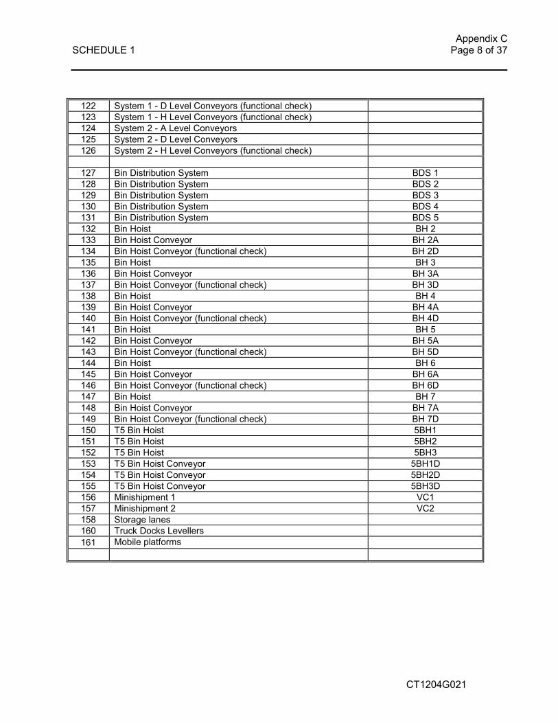
122 System 1 - D Level Conveyors (functional check) 123 System 1 - H Level Conveyors (functional check) 124 System 2 - A Level Conveyors 125 System 2 - D Level Conveyors 126 System 2 - H Level Conveyors (functional check)
127 Bin Distribution System BDS 1 128 Bin Distribution System BDS 2 129 Bin Distribution System BDS 3 130 Bin Distribution System BDS 4 131 Bin Distribution System BDS 5 132 Bin Hoist BH 2 133 Bin Hoist Conveyor BH 2A 134 Bin Hoist Conveyor (functional check) BH 2D
135 Bin Hoist BH 3 136 Bin Hoist Conveyor BH 3A 137 Bin Hoist Conveyor (functional check) BH 3D 138 Bin Hoist BH 4 139 Bin Hoist Conveyor BH 4A 140 Bin Hoist Conveyor (functional check) BH 4D 141 Bin Hoist BH 5 142 Bin Hoist Conveyor BH 5A 143 Bin Hoist Conveyor (functional check) BH 5D 144 Bin Hoist BH 6 145 Bin Hoist Conveyor BH 6A 146 Bin Hoist Conveyor (functional check) BH 6D 147 Bin Hoist BH 7
148 Bin Hoist Conveyor BH 7A 149 Bin Hoist Conveyor (functional check) BH 7D 150 T5 Bin Hoist 5BH1 151 T5 Bin Hoist 5BH2 152 T5 Bin Hoist 5BH3 153 T5 Bin Hoist Conveyor 5BH1D 154 T5 Bin Hoist Conveyor 5BH2D 155 T5 Bin Hoist Conveyor 5BH3D 156 Minishipment 1 VC1 157 Minishipment 2 VC2 158 Storage lanes 160 Truck Docks Levellers
161 Mobile platforms
Appendix C SCHEDULE 1 Page 9 of 37
CT1204G021
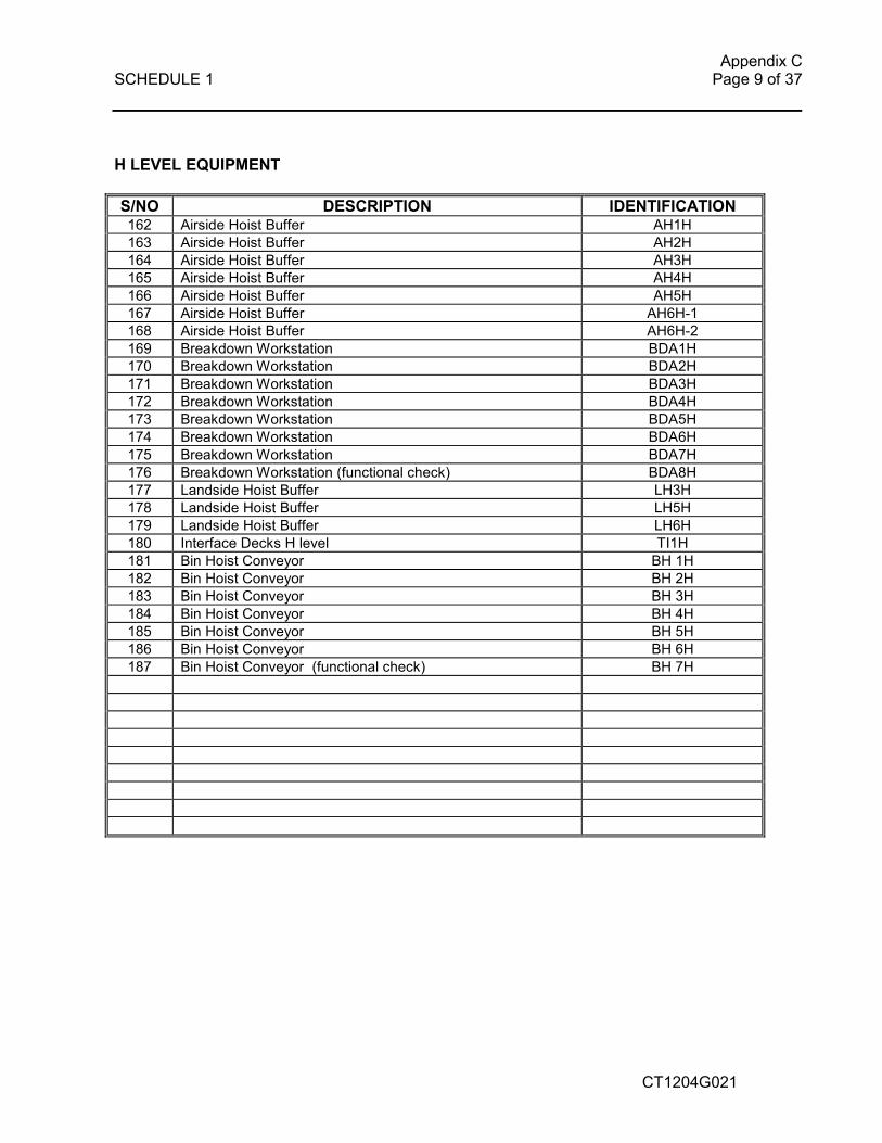
H LEVEL EQUIPMENT
S/NO DESCRIPTION IDENTIFICATION 162 Airside Hoist Buffer AH1H 163 Airside Hoist Buffer AH2H 164 Airside Hoist Buffer AH3H 165 Airside Hoist Buffer AH4H 166 Airside Hoist Buffer AH5H 167 Airside Hoist Buffer AH6H-1 168 Airside Hoist Buffer AH6H-2 169 Breakdown Workstation BDA1H 170 Breakdown Workstation BDA2H 171 Breakdown Workstation BDA3H 172 Breakdown Workstation BDA4H 173 Breakdown Workstation BDA5H 174 Breakdown Workstation BDA6H
175 Breakdown Workstation BDA7H 176 Breakdown Workstation (functional check) BDA8H 177 Landside Hoist Buffer LH3H 178 Landside Hoist Buffer LH5H 179 Landside Hoist Buffer LH6H 180 Interface Decks H level TI1H 181 Bin Hoist Conveyor BH 1H 182 Bin Hoist Conveyor BH 2H 183 Bin Hoist Conveyor BH 3H 184 Bin Hoist Conveyor BH 4H 185 Bin Hoist Conveyor BH 5H 186 Bin Hoist Conveyor BH 6H 187 Bin Hoist Conveyor (functional check) BH 7H
Appendix C SCHEDULE 1 Page 10 of 37
CT1204G021
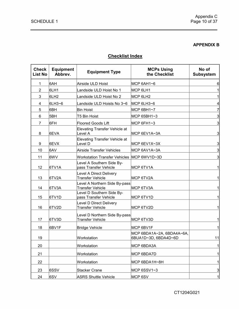
APPENDIX B
Checklist Index
Check List No
Equipment Abbrev.
Equipment Type MCPs Using the Checklist
No of Subsystem
1 6AH Airside ULD Hoist MCP 6AH1~6 6
2 6LH1 Landside ULD Hoist No 1 MCP 6LH1 1
3 6LH2 Landside ULD Hoist No 2 MCP 6LH2 1
4 6LH3~6 Landside ULD Hoists No 3~6 MCP 6LH3~6 4
5 6BH Bin Hoist MCP 6BH1~7 7
6 5BH T5 Bin Hoist MCP 65BH1~3 3
7 6FH Floored Goods Lift MCP 6FH1~3 3
8 6EVA Elevating Transfer Vehicle at Level A MCP 6EV1A~3A 3
9 6EVX Elevating Transfer Vehicle at Level D MCP 6EV1X~3X 3
10 6AV Airside Transfer Vehicles MCP 6AV1A~3A 3
11 6WV Workstation Transfer Vehicles MCP 6WV1D~3D 3
12 6TV1A Level A Southern Side By-pass Transfer Vehicle MCP 6TV1A 1
13 6TV2A Level A Direct Delivery Transfer Vehicle MCP 6TV2A 1
14 6TV3A Level A Northern Side By-pass Transfer Vehicle MCP 6TV3A 1
15 6TV1D Level D Southern Side By-pass Transfer Vehicle MCP 6TV1D 1
16 6TV2D Level D Direct Delivery Transfer Vehicle MCP 6TV2D 1
17 6TV3D Level D Northern Side By-pass Transfer Vehicle MCP 6TV3D 1
18 6BV1F Bridge Vehicle MCP 6BV1F 1
19 Workstation MCP 6BDA1A~2A, 6BDA4A~6A, 6BUA1D~3D, 6BDA4D~6D 11
20 Workstation MCP 6BDA3A 1
21 Workstation MCP 6BDA7D 1
22 Workstation MCP 6BDA1H~8H 1
23 6SSV Stacker Crane MCP 6SSV1~3 3
24 6SV ASRS Shuttle Vehicle MCP 6SV 1

Appendix C SCHEDULE 1 Page 11 of 37
CT1204G021
25 6BDS Bin Disrtibution System MCP BDS1~10 10
26 6BIO Bin Input/Output Station MCP 6BH1A~7A, 6BH1D~7D, 6BH1H~7H 24
27 6MiniSM Minishipment Vertical Carousel MCP 6V1A~2A, 6V1~2D 2
28 6FRD Friction Roller Deck
All FRDs at Level A, B, D, E, F, H
29 6HW & 6AHD High Way Decks & Airside ULD Hoist Interfacing Decks
MCP 6HW1~7, 6AH1A~6A, 6AH1D~6D, 6AH1F~6F, 6AH1H~6H 31
30 6LHD Landside ULD Hoist Interfacing Decks
MCP 6LH1A, 6LH3A~6A, 6LH1D, 6LH3D~6D, 6LH3H~6H 14
31 6QA ULD Queue Lane MCP 6QA-1~4 4
32 6RQ1A Refrigerated Queue Lane MCP RQ1A 1
33 Level A & D Direct Delivery Workstation-1 MCP 6DA1A-1, 6DC1D-1 2
34 Level A & D Direct Delivery Workstation-2 MCP 6DA1A-2, 6DC1D-2 2
35 Level A Northern Side Direct Delivery Workstation MCP 6DB1A 1
36 Level D Northern Side Direct Delivery Workstation MCP 6DD1D 1
37 6ID1A Scissors Lifts at Level A MCP 6ID1A~3A 3
38 6ED1D Scissors Lifts at Level D MCP 6ED1D~3D 3
39 6FD Truck Dock at Level A & D MCP 6FD1A, 6FD1D 2
40 LH1 Interface Decks MCP 6LH1A & 6LH1D
41 6TD Transfer Decks MCP 6TD1~3 3
42 Interfacing Decks Between T5 & T6
MCP 6TI1D-1, 6TI1F-1, 6TI1F-2, 6TI1H 4
43 Interfacing Decks Between T5 & T6 6TI1D-2 1
44 6SP Spineline Decks MCP 6SP1~9 9
Appendix C SCHEDULE 1 Page 12 of 37
CT1204G021
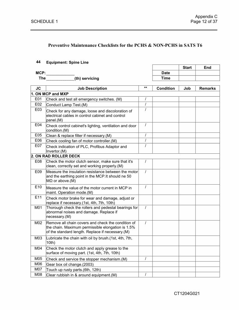
Preventive Maintenance Checklists for the PCHS & NON-PCHS in SATS T6
44 Equipment: Spine Line
Start End MCP: _____________ Date The _____________(th) servicing Time
JC Job Description ** Condition Job Remarks
1. ON MCP and MXP E01 Check and test all emergency switches. (M) / E02 Conduct Lamp Test.(M) / E03 Check for any damage, loose and discoloration of
electrical cables in control cabinet and control panel.(M)
/
E04 Check control cabinet's lighting, ventilation and door
condition.(M)
/
E05 Clean & replace filter if necessary.(M) / E06 Check cooling fan of motor controller.(M) / E07 Check indication of PLC, Profibus Adaptor and
Invertor.(M)
/
2. ON RAD ROLLER DECK E08 Check the motor clutch sensor, make sure that it's
clean, correctly set and working properly.(M) /
E09 Measure the insulation resistance between the motor and the earthing point in the MCP.It should ne 50 MΩ or above.(M)
/
E10 Measure the value of the motor current in MCP in maint. Operation mode.(M)
/
E11 Check motor brake for wear and damage, adjust or replace if necessary.(1st, 4th, 7th, 10th)
M01 Thorough check the rollers and pedestal bearings for abnormal noises and damage. Replace if necessary.(M)
/
M02 Remove all chain covers and check the condition of the chain. Maximum permissible elongation is 1.5% of the standard length. Replace if necessary.(M)
/
M03 Lubricate the chain with oil by brush.(1st, 4th, 7th, 10th)
M04 Check the motor clutch and apply grease to the surface of moving part. (1st, 4th, 7th, 10th)
M05 Check and service the stopper mechanism.(M) / M06 Gear box oil change.(2003) M07 Touch up rusty parts.(6th, 12th) M08 Clear rubbish in & around equipment.(M) /

Appendix C SCHEDULE 1 Page 13 of 37
CT1204G021
3. ON RAD WHEEL DECK
E12 Check the motor clutch sensor, make sure that it's clean, correctly set and working properly with the clutch engaged/disengaged.(M)
/
E13 Clean and check that all the ULD movement sensors are activated when covered with a hand. Also check the installation of sensors and sensor cables.(M)
/
E14 Measure the insulation resistance between the motor and the earthing point in the MCP.It should be 50 MΩ or above.(M)
/
E15 Measure the value of the motor current in MCP in maint. Operation mode.(M)
/
E16 Check motor brake for wear and damage, adjust or replace if necessary.(1st, 4th, 7th, 10th)
M09 Remove all walkways and thoroughly check the rotation of wheels for abnomal noises.(M)
/
M10 Check the condition of wheel chains. Maximum permissible elongation is 1.5% of the standard length. Replace if necessary.(M)
/
M11 Check the tension of wheel drive chains. Adjust with the chain tensioner if necessary.(M)
/
M12 Lubricate all the chains with the oil by brush.(1st, 4th, 7th, 10th)
M13 Check the motor clutch and apply grease to the surface of moving part. (1st, 4th, 7th, 10th)
M14 Check and service the stopper mechanism.(M) / M15
Using the special tool to lift up the roller frame, check the condition of the center shaft for the wheel drive and carry out: 1) clean dirt. 2) check for deformation. 3) tuch up rusty part or apply anti-rust oil (NP-3).(1st, 4th, 7th, 10th)
M16 Gear box oil change.(2003) M17 Touch up rusty parts.(6th, 12th) M18 Clear rubbish in & around equipment.(M) /
4. ON RAD CAM LIFTING MECHANISM E17 Check that the upper and lower position proximity
sensors are clean, correctly set and working properly with the cam shaft rotated. Adjust if necessary. (M)
/
E18 Check the motor clutch sensor, make sure that it's
clean, correctly set and working properly with a metal piece brought closely.(M)
/
E19 Measure the insulation resistance between the motor
and the earthing point in the MCP.It should be 50 MΩ or above.(M)
/
E20 Measure the value of the motor current in MCP in maint. Operation mode.(M)
/

Appendix C SCHEDULE 1 Page 14 of 37
CT1204G021
E21 Check motor brake for wear and damage, adjust or replace if necessary.(1st, 4th, 7th, 10th)
M19 Check the cam chaft assembly for abnormal noises
and interference with the cam rotated. (M)
/
M20 Check the condition of cam and cam follower, carry out: 1) clean dirt and rust. 2) check for deformation. 3) touch up rusty parts or apply anti-rust oil (NP-3). 4) grease cam followers (8 places).(1st, 4th, 7th, 10th)
M21
Check the condition of lower frame, guiding device and cam shaft, carry out: 1) clean dirt and rust. 2) check for deformation. 3) touch up rusty parts or apply anti-rust oil (NP-3).(1st, 4th, 7th, 10th)
M22
Reinstall the roller deck with the special tool and put back the walkways. Check for abnormal noises, interference and vibration with each motor operated.(M)
/
M23 Gear box oil change.(2003)
5. ON OMNIMAT QUEUE CONVEYOR E22 Check that the upper and lower position proximity
sensors are clean, correctly set and working properly with the cam shaft rotated. Adjust if necessary. (M)
/
E23 Check both roller deck and lifting deck drive motor clutch sensors, make sure that they are clean, correctly set and working properly with a metal piece brought closely.(M)
/
E24 Measure the insulation resistance between the motors and the earthing point in the MCP. They should be 50 MΩ or above.(M)
/
E25 Measure the value of both motor current in MCP in maint. Operation mode.(M)
/
E26 Check motor brakes for wear and damage, adjust or replace if necessary.(1st, 4th, 7th, 10th)
M28 Grease lifting guide rollers.(6th, 12th)
M29 Grease cam shaft bearing units by grease gun.(6th, 12th)
M30 Check the condition of all drive chains. Maximum permissible elongation is 1.5% of the standard length. Adjust chain tensioner or replace if necessary.(M)
/
M31 Lubricate all the roller chains.(1st, 4th, 7th, 10th)
M32 Grease bearings of chain tensioners.(1st, 4th, 7th, 10th)
M33 Roller deck and lifting deck drive motor gear boxes oil change. (2003)
M34 Clear rubbish in & around equipment.(M) / M35 Check all fasteners are properly tensioned.(M) /
Appendix C SCHEDULE 1 Page 15 of 37
CT1204G021
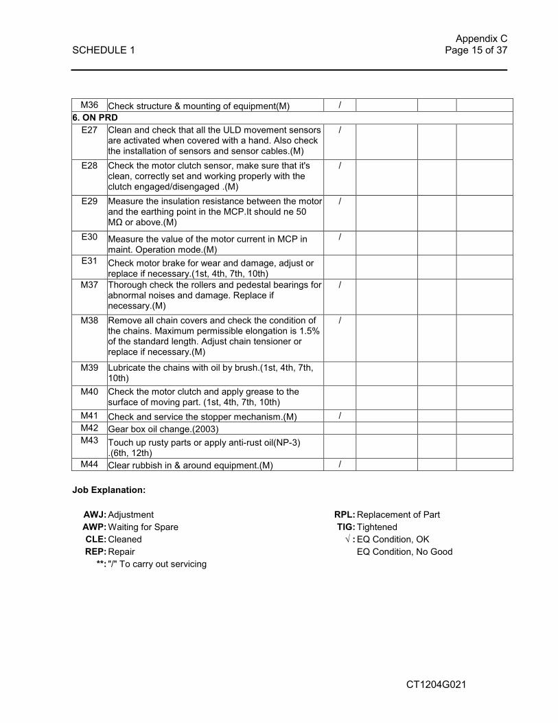
M36 Check structure & mounting of equipment(M) /
6. ON PRD E27 Clean and check that all the ULD movement sensors
are activated when covered with a hand. Also check the installation of sensors and sensor cables.(M)
/
E28 Check the motor clutch sensor, make sure that it's clean, correctly set and working properly with the clutch engaged/disengaged .(M)
/
E29 Measure the insulation resistance between the motor and the earthing point in the MCP.It should ne 50 MΩ or above.(M)
/
E30 Measure the value of the motor current in MCP in maint. Operation mode.(M)
/
E31 Check motor brake for wear and damage, adjust or replace if necessary.(1st, 4th, 7th, 10th)
M37 Thorough check the rollers and pedestal bearings for abnormal noises and damage. Replace if necessary.(M)
/
M38 Remove all chain covers and check the condition of the chains. Maximum permissible elongation is 1.5% of the standard length. Adjust chain tensioner or replace if necessary.(M)
/
M39 Lubricate the chains with oil by brush.(1st, 4th, 7th, 10th)
M40 Check the motor clutch and apply grease to the surface of moving part. (1st, 4th, 7th, 10th)
M41 Check and service the stopper mechanism.(M) / M42 Gear box oil change.(2003) M43 Touch up rusty parts or apply anti-rust oil(NP-3)
.(6th, 12th)
M44 Clear rubbish in & around equipment.(M) /
Job Explanation:
AWJ: Adjustment RPL: Replacement of Part
AWP: Waiting for Spare TIG: Tightened
CLE: Cleaned √ : EQ Condition, OK
REP: Repair EQ Condition, No Good **: "/" To carry out servicing
Appendix C SCHEDULE 1 Page 16 of 37
CT1204G021
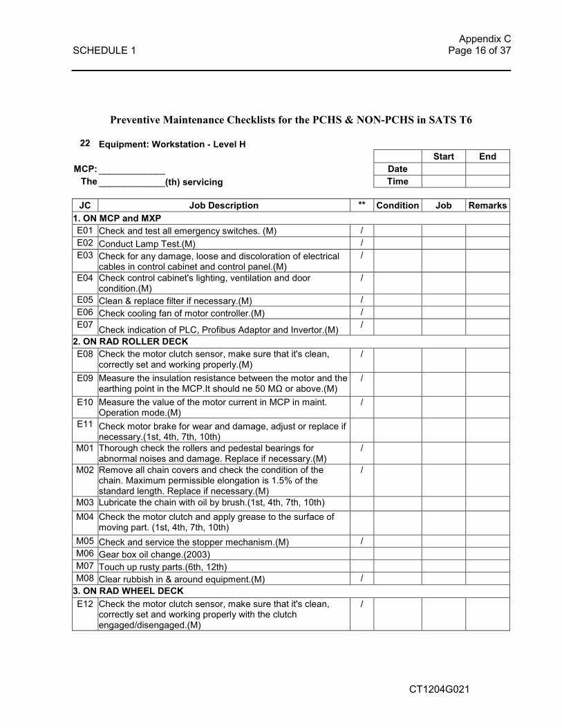
Preventive Maintenance Checklists for the PCHS & NON-PCHS in SATS T6
22 Equipment: Workstation - Level H
Start End MCP: _____________ Date The _____________(th) servicing Time
JC Job Description ** Condition Job Remarks
1. ON MCP and MXP E01 Check and test all emergency switches. (M) / E02 Conduct Lamp Test.(M) / E03 Check for any damage, loose and discoloration of electrical
cables in control cabinet and control panel.(M)
/
E04 Check control cabinet's lighting, ventilation and door
condition.(M) /
E05 Clean & replace filter if necessary.(M) / E06 Check cooling fan of motor controller.(M) / E07
Check indication of PLC, Profibus Adaptor and Invertor.(M) /
2. ON RAD ROLLER DECK E08 Check the motor clutch sensor, make sure that it's clean,
correctly set and working properly.(M) /
E09 Measure the insulation resistance between the motor and the earthing point in the MCP.It should ne 50 MΩ or above.(M)
/
E10 Measure the value of the motor current in MCP in maint. Operation mode.(M)
/
E11 Check motor brake for wear and damage, adjust or replace if necessary.(1st, 4th, 7th, 10th)
M01 Thorough check the rollers and pedestal bearings for abnormal noises and damage. Replace if necessary.(M)
/
M02 Remove all chain covers and check the condition of the chain. Maximum permissible elongation is 1.5% of the standard length. Replace if necessary.(M)
/
M03 Lubricate the chain with oil by brush.(1st, 4th, 7th, 10th)
M04 Check the motor clutch and apply grease to the surface of moving part. (1st, 4th, 7th, 10th)
M05 Check and service the stopper mechanism.(M) / M06 Gear box oil change.(2003) M07 Touch up rusty parts.(6th, 12th) M08 Clear rubbish in & around equipment.(M) /
3. ON RAD WHEEL DECK
E12 Check the motor clutch sensor, make sure that it's clean, correctly set and working properly with the clutch engaged/disengaged.(M)
/
Appendix C SCHEDULE 1 Page 17 of 37
CT1204G021
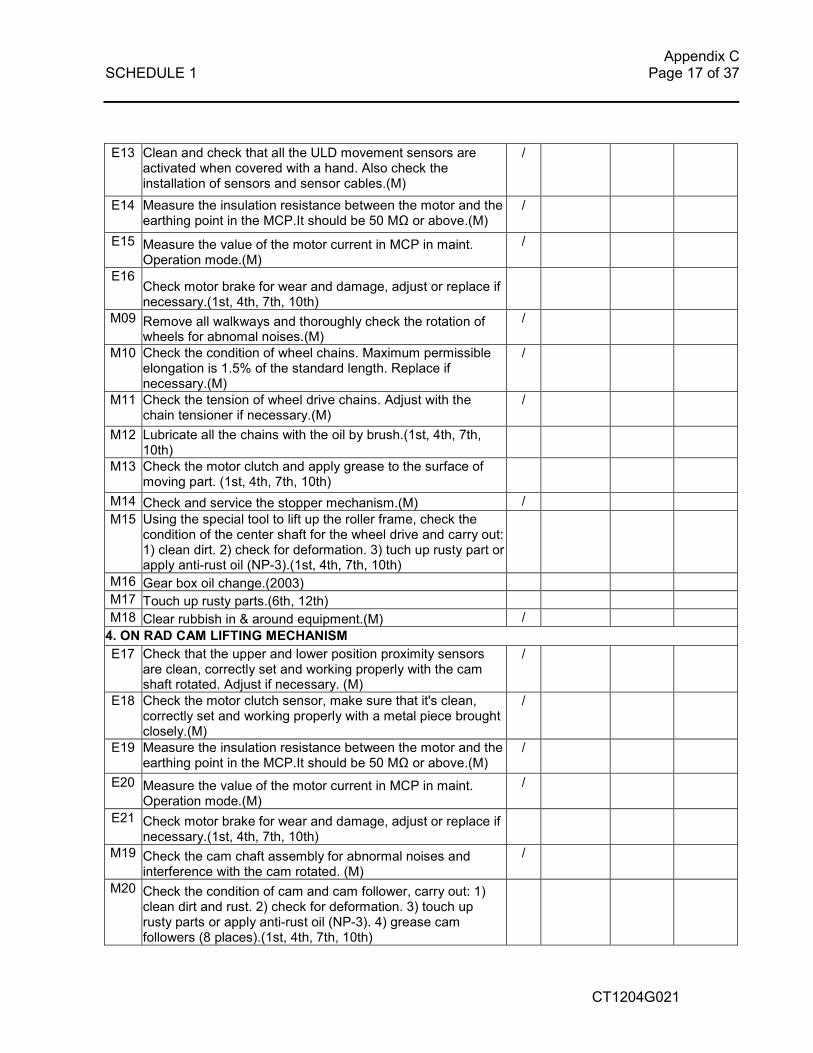
E13 Clean and check that all the ULD movement sensors are activated when covered with a hand. Also check the installation of sensors and sensor cables.(M)
/
E14 Measure the insulation resistance between the motor and the earthing point in the MCP.It should be 50 MΩ or above.(M)
/
E15 Measure the value of the motor current in MCP in maint. Operation mode.(M)
/
E16 Check motor brake for wear and damage, adjust or replace if necessary.(1st, 4th, 7th, 10th)
M09 Remove all walkways and thoroughly check the rotation of wheels for abnomal noises.(M)
/
M10 Check the condition of wheel chains. Maximum permissible elongation is 1.5% of the standard length. Replace if necessary.(M)
/
M11 Check the tension of wheel drive chains. Adjust with the chain tensioner if necessary.(M)
/
M12 Lubricate all the chains with the oil by brush.(1st, 4th, 7th, 10th)
M13 Check the motor clutch and apply grease to the surface of moving part. (1st, 4th, 7th, 10th)
M14 Check and service the stopper mechanism.(M) / M15 Using the special tool to lift up the roller frame, check the
condition of the center shaft for the wheel drive and carry out: 1) clean dirt. 2) check for deformation. 3) tuch up rusty part or apply anti-rust oil (NP-3).(1st, 4th, 7th, 10th)
M16 Gear box oil change.(2003) M17 Touch up rusty parts.(6th, 12th) M18 Clear rubbish in & around equipment.(M) /
4. ON RAD CAM LIFTING MECHANISM E17 Check that the upper and lower position proximity sensors
are clean, correctly set and working properly with the cam shaft rotated. Adjust if necessary. (M)
/
E18 Check the motor clutch sensor, make sure that it's clean,
correctly set and working properly with a metal piece brought closely.(M)
/
E19 Measure the insulation resistance between the motor and the
earthing point in the MCP.It should be 50 MΩ or above.(M) /
E20 Measure the value of the motor current in MCP in maint. Operation mode.(M)
/
E21 Check motor brake for wear and damage, adjust or replace if necessary.(1st, 4th, 7th, 10th)
M19 Check the cam chaft assembly for abnormal noises and
interference with the cam rotated. (M)
/
M20 Check the condition of cam and cam follower, carry out: 1) clean dirt and rust. 2) check for deformation. 3) touch up rusty parts or apply anti-rust oil (NP-3). 4) grease cam followers (8 places).(1st, 4th, 7th, 10th)

Appendix C SCHEDULE 1 Page 18 of 37
CT1204G021
M21 Check the condition of lower frame, guiding device and cam shaft, carry out: 1) clean dirt and rust. 2) check for deformation. 3) touch up rusty parts or apply anti-rust oil (NP-3).(1st, 4th, 7th, 10th)
M22 Reinstall the roller deck with the special tool and put back the
walkways. Check for abnormal noises, interference and vibration with each motor operated.(M)
/
M23 Gear box oil change.(2003)
5. ON PRD E22 Clean and check that all the ULD movement sensors are
activated when covered with a hand. Also check the installation of sensors and sensor cables.(M)
/
E23 Check the motor clutch sensor, make sure that it's clean, correctly set and working properly with the clutch engaged/disengaged .(M)
/
E24 Measure the insulation resistance between the motor and the earthing point in the MCP.It should ne 50 MΩ or above.(M)
/
E25 Measure the value of the motor current in MCP in maint. Operation mode.(M)
/
E26 Check motor brake for wear and damage, adjust or replace if necessary.(1st, 4th, 7th, 10th)
M24 Thorough check the rollers and pedestal bearings for abnormal noises and damage. Replace if necessary.(M)
/
M25 Remove all chain covers and check the condition of the chains. Maximum permissible elongation is 1.5% of the standard length. Adjust chain tensioner or replace if necessary.(M)
/
M26 Lubricate the chains with oil by brush.(1st, 4th, 7th, 10th)
M27 Check the motor clutch and apply grease to the surface of moving part. (1st, 4th, 7th, 10th)
M28 Check and service the stopper mechanism.(M) / M29 Gear box oil change.(2003) M30 Touch up rusty parts or apply anti-rust oil(NP-3) .(6th, 12th) M31 Clear rubbish in & around equipment.(M) /
6. ON SISSORS LIFT ROLLER DECK E27 Clean and check that all the ULD movement sensors are
activated when covered with a hand. Also check the installation of sensors and sensor cables.(M)
/
E28 Check the motor clutch sensor, make sure that it's clean, correctly set and working properly with the clutch engaged/disengaged .(M)
/
E29 Measure the insulation resistance between the motor and the earthing point in the MCP.It should ne 50 MΩ or above.(M)
/
E30 Measure the value of the motor current in MCP in maint. Operation mode.(M)
/
E31 Check motor brake for wear and damage, adjust or replace if necessary.(1st, 4th, 7th, 10th)
M32 Thorough check the rollers and pedestal bearings for abnormal noises and damage. Replace if necessary.(M)
/
Appendix C SCHEDULE 1 Page 19 of 37
CT1204G021
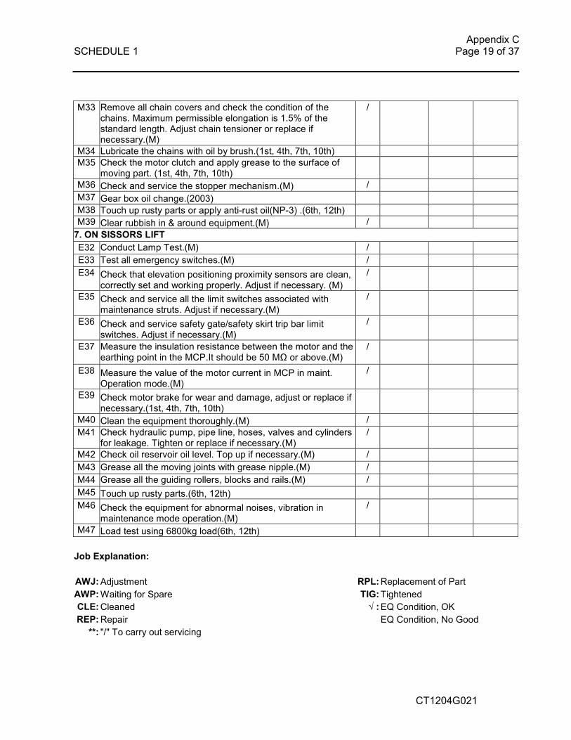
M33 Remove all chain covers and check the condition of the chains. Maximum permissible elongation is 1.5% of the standard length. Adjust chain tensioner or replace if necessary.(M)
/
M34 Lubricate the chains with oil by brush.(1st, 4th, 7th, 10th) M35 Check the motor clutch and apply grease to the surface of
moving part. (1st, 4th, 7th, 10th)
M36 Check and service the stopper mechanism.(M) / M37 Gear box oil change.(2003) M38 Touch up rusty parts or apply anti-rust oil(NP-3) .(6th, 12th) M39 Clear rubbish in & around equipment.(M) /
7. ON SISSORS LIFT E32 Conduct Lamp Test.(M) /
E33 Test all emergency switches.(M) /
E34 Check that elevation positioning proximity sensors are clean, correctly set and working properly. Adjust if necessary. (M)
/
E35 Check and service all the limit switches associated with maintenance struts. Adjust if necessary.(M)
/
E36 Check and service safety gate/safety skirt trip bar limit switches. Adjust if necessary.(M)
/
E37 Measure the insulation resistance between the motor and the earthing point in the MCP.It should be 50 MΩ or above.(M)
/
E38 Measure the value of the motor current in MCP in maint. Operation mode.(M)
/
E39 Check motor brake for wear and damage, adjust or replace if necessary.(1st, 4th, 7th, 10th)
M40 Clean the equipment thoroughly.(M) /
M41 Check hydraulic pump, pipe line, hoses, valves and cylinders for leakage. Tighten or replace if necessary.(M)
/
M42 Check oil reservoir oil level. Top up if necessary.(M) /
M43 Grease all the moving joints with grease nipple.(M) /
M44 Grease all the guiding rollers, blocks and rails.(M) /
M45 Touch up rusty parts.(6th, 12th)
M46 Check the equipment for abnormal noises, vibration in maintenance mode operation.(M)
/
M47 Load test using 6800kg load(6th, 12th)
Job Explanation:
AWJ: Adjustment RPL: Replacement of Part AWP: Waiting for Spare TIG: Tightened
CLE: Cleaned √ : EQ Condition, OK
REP: Repair EQ Condition, No Good **: "/" To carry out servicing

Appendix C SCHEDULE 1 Page 20 of 37
CT1204G021
Preventive Maintenance Checklists for the PCHS & NON-PCHS in SATS T6
29 Equipment: Highway Decks and Airside ULD Hoist Interfacing Decks
Start End MCP: _____________ Date The _____________(th) servicing Time
JC Job Description ** Condition Job Remarks
1. ON MCP and MXP E01 Check and test all emergency switches. (M) / E02 Conduct Lamp Test.(M) / E03 Check for any damage, loose and discoloration of electrical
cables in control cabinet and control panel.(M)
/
E04 Check control cabinet's lighting, ventilation and door
condition.(M)
/
E05 Clean & replace filter if necessary.(M) / E06 Check cooling fan of motor controller.(M) / E07
Check indication of PLC, Profibus Adaptor and Invertor.(M) /
2. ON RAD ROLLER DECK E08 Check the motor clutch sensor, make sure that it's clean,
correctly set and working properly.(M) /
E09 Measure the insulation resistance between the motor and the earthing point in the MCP.It should ne 50 MΩ or above.(M)
/
E10 Measure the value of the motor current in MCP in maint. Operation mode.(M)
/
E11 Check motor brake for wear and damage, adjust or replace if necessary.(1st, 4th, 7th, 10th)
M01 Thorough check the rollers and pedestal bearings for abnormal noises and damage. Replace if necessary.(M)
/
M02 Remove all chain covers and check the condition of the chain. Maximum permissible elongation is 1.5% of the standard length. Replace if necessary.(M)
/
M03 Lubricate the chain with oil by brush.(1st, 4th, 7th, 10th)
M04 Check the motor clutch and apply grease to the surface of moving part. (1st, 4th, 7th, 10th)
M05 Check and service the stopper mechanism.(M) / M06 Gear box oil change.(2003) M07 Touch up rusty parts.(6th, 12th) M08 Clear rubbish in & around equipment.(M) /
3. ON RAD WHEEL DECK E12 Check the motor clutch sensor, make sure that it's clean,
correctly set and working properly with the clutch engaged/disengaged.(M)
/

Appendix C SCHEDULE 1 Page 21 of 37
CT1204G021
E13 Clean and check that all the ULD movement sensors are activated when covered with a hand. Also check the installation of sensors and sensor cables.(M)
/
E14 Measure the insulation resistance between the motor and the earthing point in the MCP.It should be 50 MΩ or above.(M)
/
E15 Measure the value of the motor current in MCP in maint. Operation mode.(M)
/
E16 Check motor brake for wear and damage, adjust or replace if necessary.(1st, 4th, 7th, 10th)
M09 Remove all walkways and thoroughly check the rotation of wheels for abnomal noises.(M)
/
M10 Check the condition of wheel chains. Maximum permissible elongation is 1.5% of the standard length. Replace if necessary.(M)
/
M11 Check the tension of wheel drive chains. Adjust with the chain tensioner if necessary.(M)
/
M12 Lubricate all the chains with the oil by brush.(1st, 4th, 7th, 10th)
M13 Check the motor clutch and apply grease to the surface of moving part. (1st, 4th, 7th, 10th)
M14 Check and service the stopper mechanism.(M) / M15
Using the special tool to lift up the roller frame, check the condition of the center shaft for the wheel drive and carry out: 1) clean dirt. 2) check for deformation. 3) tuch up rusty part or apply anti-rust oil (NP-3).(1st, 4th, 7th, 10th)
M16 Gear box oil change.(2003) M17 Touch up rusty parts.(6th, 12th) M18 Clear rubbish in & around equipment.(M) /
4. ON RAD CAM LIFTING MECHANISM E17 Check that the upper and lower position proximity sensors are
clean, correctly set and working properly with the cam shaft rotated. Adjust if necessary. (M)
/
E18 Check the motor clutch sensor, make sure that it's clean,
correctly set and working properly with a metal piece brought closely.(M)
/
E19 Measure the insulation resistance between the motor and the
earthing point in the MCP.It should be 50 MΩ or above.(M) /
E20 Measure the value of the motor current in MCP in maint. Operation mode.(M)
/
E21 Check motor brake for wear and damage, adjust or replace if
necessary.(1st, 4th, 7th, 10th)
M19 Check the cam chaft assembly for abnormal noises and
interference with the cam rotated. (M)
/
M20 Check the condition of cam and cam follower, carry out: 1) clean dirt and rust. 2) check for deformation. 3) touch up rusty parts or apply anti-rust oil (NP-3). 4) grease cam followers (8

Appendix C SCHEDULE 1 Page 22 of 37
CT1204G021
places).(1st, 4th, 7th, 10th)
M21 Check the condition of lower frame, guiding device and cam shaft, carry out: 1) clean dirt and rust. 2) check for deformation. 3) touch up rusty parts or apply anti-rust oil (NP-3).(1st, 4th, 7th, 10th)
M22 Reinstall the roller deck with the special tool and put back the
walkways. Check for abnormal noises, interference and vibration with each motor operated.(M)
/
M23 Gear box oil change.(2003)
5. ON PRD E22 Clean and check that all the ULD movement sensors are
activated when covered with a hand. Also check the installation of sensors and sensor cables.(M)
/
E23 Check the motor clutch sensor, make sure that it's clean, correctly set and working properly with the clutch engaged/disengaged .(M)
/
E24 Measure the insulation resistance between the motor and the earthing point in the MCP.It should ne 50 MΩ or above.(M)
/
E25 Measure the value of the motor current in MCP in maint. Operation mode.(M)
/
E26 Check motor brake for wear and damage, adjust or replace if necessary.(1st, 4th, 7th, 10th)
M24 Thorough check the rollers and pedestal bearings for abnormal noises and damage. Replace if necessary.(M)
/
M25 Remove all chain covers and check the condition of the chains. Maximum permissible elongation is 1.5% of the standard length. Adjust chain tensioner or replace if necessary.(M)
/
M26 Lubricate the chains with oil by brush.(1st, 4th, 7th, 10th)
M27 Check the motor clutch and apply grease to the surface of moving part. (1st, 4th, 7th, 10th)
M28 Check and service the stopper mechanism.(M) / M29 Gear box oil change.(2003) M30 Touch up rusty parts or apply anti-rust oil(NP-3) .(6th, 12th) M31 Clear rubbish in & around equipment.(M) / M32 Load test on whole subsystem using 6800kg load(6th, 12th)
Job Explanation:
AWJ: Adjustment RPL: Replacement of Part AWP: Waiting for Spare TIG: Tightened
CLE: Cleaned √ : EQ Condition, OK
REP: Repair EQ Condition, No Good **: "/" To carry out servicing

Appendix C SCHEDULE 1 Page 23 of 37
CT1204G021
Appendix C
From : To :
Date Serv no. Abbrev Equipment Type M D Date Serv no. Abbrev Equipment Type M D10-Oct-02 16 6AH2 Airside Hoist 4 F 13-Oct-02Thu 16 6AH2A Interface Decks-Level A Sun Non-service day
0800-1700 16 FRD Storage Lanes A26A-A31A
13 6BDA5D Workstation-Level D 4 F
16 6AH2D Interface Decks-Level D 3 F
13 6AH2F Interface Decks-Level F 3 F Date Serv no. Abbrev Equipment Type M D13 6AH2H Interface Decks-Level H 5 F 14-Oct-02 15 5BH1-2 T5 Bin Hoist (inclusive of BIO) 6 F
Mon 15 6BDS1 BDS Conveyors 6 F
15 6BDS2 BDS Conveyors 6 F
Date Serv no. Abbrev Equipment Type M D 15 6BDS3 BDS Conveyors 6 F
11-Oct-02 13 6LH6 Landside Hoist 3 F
Fri 13 6LH6A Interface Decks-Level A 3 F Date Serv no. Abbrev Equipment Type M D0800-1700 13 6LH6D Interface Decks-Level D 3 F 15-Oct-02 16 6EV1X Elevating Transfer Vehicle-Level D 6 F
13 6LH6H Interface Decks-Level H 3 F Tue 16 FRD Storage Lanes 5-12, Level D-Level H F
15 6BDS6 BDS Conveyors 4 F 0800-1700 16 6TD-1 Transfer Decks 4 F
15 6BDS7 BDS Conveyors 5 F 16 FRD Storage Lanes L06D-L29D F
15 6BH3 Bin Hoist (inclusive of BIO) 3 F 13 6SP1 Spine Line Conveyors 6 F
13 6BDA1H Workstation-Level H F
13 6TI1H T5 Interface Level H 6 F
Date Serv no. Abbrev Equipment Type M D 13 6LH2 Landside Hoist 2 F
12-Oct-02 5 FRD Storage Lanes 6L17B-6L32B 8 H Note: EV2X domain to cover up to 15.
Sat 5 FRD Storage Lanes 6L37B-6L71B 8
Note: EV1A/2A should be available for
the servicing. Date Serv no. Abbrev Equipment Type M D16-Oct-02 16 6QA-1 Queue Lane 4 F
Wed 16 6EV1A Elevating Transfer Vehicle-Level A 5 F
0800-1700 16 FRD B-Level, 6L10B-15B F
16 6BDA1A Workstation-Level A 4 F
13 6BDA4D Workstation-Level D 4 F
13 6FH1-2 Floored Goods Lift 7 F
Note:
the 9th(Oct.-Nov.) PM Schedule for the MHS at SATS T6
13-Nov-0210-Oct-02
5 F
EV2A's domain to be extended to lane 17.


Appendix C SCHEDULE 1 Page 25 of 37
CT1204G021
Appendix D 1. OVERALL WEEKLY STATISTICAL REPORT 1.1 Equipment Serviceability
Equipment : Serviceability : PM Hours : Remarks e.g. spare part used etc
:
1.2 The above is to be tabulated for all equipment in AFT6 as follows :
Equipment Serviceability PM Hours Remarks
1.3 Preventive Maintenance Summary 1.3.1 PM Hours
PM hours (office hours) : PM hours (after office hours) : Total PM Hours :
1.4 Repair 1.4.1 Repair Hours
Repair hours (office hours) : Repair hours (after office hours) : Total Repair Hours :
1.5 Completed servicing checklist for the week. 1.6 Attendance Sheet.
Appendix C SCHEDULE 1 Page 26 of 37
CT1204G021
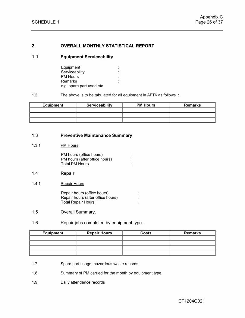
2 OVERALL MONTHLY STATISTICAL REPORT 1.1 Equipment Serviceability
Equipment : Serviceability : PM Hours : Remarks e.g. spare part used etc
:
1.2 The above is to be tabulated for all equipment in AFT6 as follows :
Equipment Serviceability PM Hours Remarks
1.3 Preventive Maintenance Summary 1.3.1 PM Hours
PM hours (office hours) : PM hours (after office hours) : Total PM Hours :
1.4 Repair 1.4.1 Repair Hours
Repair hours (office hours) : Repair hours (after office hours) : Total Repair Hours :
1.5 Overall Summary. 1.6 Repair jobs completed by equipment type.
Equipment Repair Hours Costs Remarks
1.7 Spare part usage, hazardous waste records 1.8 Summary of PM carried for the month by equipment type.
1.9 Daily attendance records

Appendix C SCHEDULE 1 Page 27 of 37
CT1204G021
B. REQUIREMENTS AND SPECIFICATIONS FOR FIRST LINE MAINTENANCE OF THE MATERIAL HANDLING SYSTEM AT SATS AIRFREIGHT TERMINAL 6
1. GENERAL 1.3 The First Line (breakdown maintenance) of the MHS at AFT 5 and 6 is currently
carried out by SATS and contractor staff. 2 OBJECTIVES OF MAINTENANCE CONTRACT 2.1 General Description 2.1.1 It is expected that the Contractor will provide the necessary manpower and tools to
support the first line (breakdown) maintenance and minor repair works in AFT 5 and 6.
2.1.2 The work is to be done over three shifts, the contractor will be required to work on
weekends and public holidays. 2.1.3 The Contractor is expected to be able to obtain manpower from other areas if the
need arises. 2.2 Objectives 2.2.1 The Contractor is expected to achieve the following :
e) High equipment serviceability rate. f) Reduce spare parts usage. c) Complete all minor repair and assist in major repair of all equipment
3 SCOPE OF WORK 3.1 ATTENDING TO BREAKDOWNS 3.1.1 The men are expected to attend to breakdowns whenever operation of
maintenance staff reports such breakdowns. The contractor is expected to provide qualified and skilled technicians to perform this work and skilled technicians to perform this work.
3.1.3 The Contractor shall follow closely the manufacturer’s recommendation in the
recovery of breakdowns. They shall follow instructions from the duty chargehand stationed at the control room.

Appendix C SCHEDULE 1 Page 28 of 37
CT1204G021
3.1.4 The work would be primarily recovery from breakdowns by resetting, adjustment or moving of ULDs. However maintenance breakdown support also includes minor repairs and assistance in major repairs where necessary.
3.1.5 The Contractor may be required to operate the equipment to retrieve urgent
shipments or to hasten the movement of ULDs. These will be part of the contract cost.
3.1.5 The Contractor shall ensure that key staff working in the terminal are contactable at all times. They are required to carry walkie talkies (these will be provided by SAS). When requested to attend to breakdowns by SAS staff they should respond with minimum delay. They should also be contactable after office hours by pager or handphone for investigation or emergencies.
3.1.6 There should be a person responsible for the scheduling and welfare of the men.
An engineer or supervisor shall be reachable by handphone in case the men do not turn up for duty.
4. TOOLS AND SPARE PARTS 4.1 The tools needed to carry out all jobs are to be provided by the Contractor
for their men. Borrowing of specialized tools from SAS can be arranged but is subject to availability. This cannot be an excuse for delay in the works that the Contractor is required to carry out.
4.2 SAS shall supply all spares and consumables.
Appendix C SCHEDULE 1 Page 29 of 37
CT1204G021
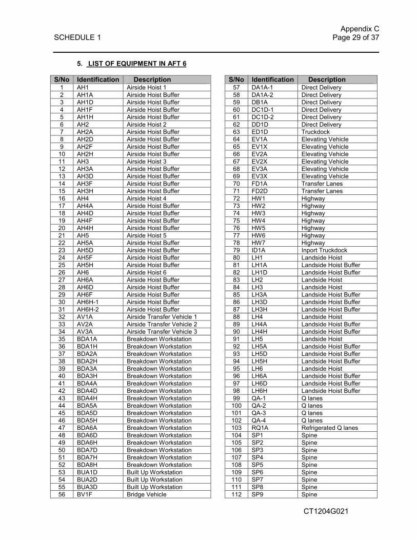
5. LIST OF EQUIPMENT IN AFT 6
S/No Identification Description S/No Identification Description 1 AH1 Airside Hoist 1 57 DA1A-1 Direct Delivery 2 AH1A Airside Hoist Buffer 58 DA1A-2 Direct Delivery 3 AH1D Airside Hoist Buffer 59 DB1A Direct Delivery 4 AH1F Airside Hoist Buffer 60 DC1D-1 Direct Delivery 5 AH1H Airside Hoist Buffer 61 DC1D-2 Direct Delivery 6 AH2 Airside Hoist 2 62 DD1D Direct Delivery 7 AH2A Airside Hoist Buffer 63 ED1D Truckdock 8 AH2D Airside Hoist Buffer 64 EV1A Elevating Vehicle 9 AH2F Airside Hoist Buffer 65 EV1X Elevating Vehicle 10 AH2H Airside Hoist Buffer 66 EV2A Elevating Vehicle 11 AH3 Airside Hoist 3 67 EV2X Elevating Vehicle 12 AH3A Airside Hoist Buffer 68 EV3A Elevating Vehicle 13 AH3D Airside Hoist Buffer 69 EV3X Elevating Vehicle 14 AH3F Airside Hoist Buffer 70 FD1A Transfer Lanes 15 AH3H Airside Hoist Buffer 71 FD2D Transfer Lanes 16 AH4 Airside Hoist 4 72 HW1 Highway 17 AH4A Airside Hoist Buffer 73 HW2 Highway 18 AH4D Airside Hoist Buffer 74 HW3 Highway 19 AH4F Airside Hoist Buffer 75 HW4 Highway 20 AH4H Airside Hoist Buffer 76 HW5 Highway 21 AH5 Airside Hoist 5 77 HW6 Highway 22 AH5A Airside Hoist Buffer 78 HW7 Highway 23 AH5D Airside Hoist Buffer 79 ID1A Inport Truckdock 24 AH5F Airside Hoist Buffer 80 LH1 Landside Hoist 25 AH5H Airside Hoist Buffer 81 LH1A Landside Hoist Buffer 26 AH6 Airside Hoist 6 82 LH1D Landside Hoist Buffer 27 AH6A Airside Hoist Buffer 83 LH2 Landside Hoist 28 AH6D Airside Hoist Buffer 84 LH3 Landside Hoist 29 AH6F Airside Hoist Buffer 85 LH3A Landside Hoist Buffer 30 AH6H-1 Airside Hoist Buffer 86 LH3D Landside Hoist Buffer 31 AH6H-2 Airside Hoist Buffer 87 LH3H Landside Hoist Buffer 32 AV1A Airside Transfer Vehicle 1 88 LH4 Landside Hoist 33 AV2A Airside Transfer Vehicle 2 89 LH4A Landside Hoist Buffer 34 AV3A Airside Transfer Vehicle 3 90 LH4H Landside Hoist Buffer 35 BDA1A Breakdown Workstation 91 LH5 Landside Hoist 36 BDA1H Breakdown Workstation 92 LH5A Landside Hoist Buffer 37 BDA2A Breakdown Workstation 93 LH5D Landside Hoist Buffer 38 BDA2H Breakdown Workstation 94 LH5H Landside Hoist Buffer 39 BDA3A Breakdown Workstation 95 LH6 Landside Hoist 40 BDA3H Breakdown Workstation 96 LH6A Landside Hoist Buffer 41 BDA4A Breakdown Workstation 97 LH6D Landside Hoist Buffer 42 BDA4D Breakdown Workstation 98 LH6H Landside Hoist Buffer 43 BDA4H Breakdown Workstation 99 QA-1 Q lanes 44 BDA5A Breakdown Workstation 100 QA-2 Q lanes 45 BDA5D Breakdown Workstation 101 QA-3 Q lanes 46 BDA5H Breakdown Workstation 102 QA-4 Q lanes 47 BDA6A Breakdown Workstation 103 RQ1A Refrigerated Q lanes 48 BDA6D Breakdown Workstation 104 SP1 Spine 49 BDA6H Breakdown Workstation 105 SP2 Spine 50 BDA7D Breakdown Workstation 106 SP3 Spine 51 BDA7H Breakdown Workstation 107 SP4 Spine 52 BDA8H Breakdown Workstation 108 SP5 Spine 53 BUA1D Built Up Workstation 109 SP6 Spine 54 BUA2D Built Up Workstation 110 SP7 Spine 55 BUA3D Built Up Workstation 111 SP8 Spine 56 BV1F Bridge Vehicle 112 SP9 Spine

Appendix C SCHEDULE 1 Page 30 of 37
CT1204G021
S/No Identification Description S/No Identification Description 113 TD-1 Transfer lanes 162 BH 2 Bin Hoist 114 TD-2 Transfer Lanes 163 BH 2A Bin Hoist Conveyor 115 TD-3 Transfer Lanes 164 BH 2D Bin Hoist Conveyor 116 TI1D-1 Interface Decks D level 165 BH 2H Bin Hoist Conveyor 117 TI1D-2 Interface Decks D level 166 BH 3 Bin Hoist 118 TI1F-1 Interface Decks F level 167 BH 3A Bin Hoist Conveyor 119 TI1F-2 Interface Decks F level 168 BH 3D Bin Hoist Conveyor 120 TI1H Interface Decks H level 169 BH 3H Bin Hoist Conveyor 121 TV1A Transfer Vehicles 170 BH 4 Bin Hoist 122 TV1D Transfer Vehicles 171 BH 4A Bin Hoist Conveyor 123 TV2A Transfer Vehicles 172 BH 4D Bin Hoist Conveyor 124 TV2D Transfer Vehicles 173 BH 4H Bin Hoist Conveyor 125 TV3A Transfer Vehicles 174 BH 5 Bin Hoist 126 TV3D Transfer Vehicles 175 BH 5A Bin Hoist Conveyor 127 UVC Vulnerable Cage 176 BH 5D Bin Hoist Conveyor 128 WV1D Workstn Transfer Vehicle 177 BH 5H Bin Hoist Conveyor 129 WV2D Workstn Transfer Vehicle 178 BH 6 Bin Hoist 130 WV3D Workstn Transfer Vehicle 179 BH 6A Bin Hoist Conveyor 131 FG1 Floor Goods Hoist 180 BH 6D Bin Hoist Conveyor 132 FG2 Floor Goods Hoist 181 BH 6H Bin Hoist Conveyor 133 FG3 Floor Goods Hoist 182 BH 7 Bin Hoist 134 SSV1 Stacker Vehicle 183 BH 7A Bin Hoist Conveyor 135 SSV2 Stacker Vehicle 184 BH 7D Bin Hoist Conveyor 136 SSV3 Stacker Vehicle 185 BH 7H Bin Hoist Conveyor 137 SV Shuttle Vehicle 186 5BH1 T5 Bin Hoist 138 SSV BH1 ASRS Bin Hoist 187 5BH2 T5 Bin Hoist 139 SSV BH2 ASRS Bin Hoist 188 5BH3 T5 Bin Hoist 140 SSV BH3 ASRS Bin Hoist 189 5BH1D T5 Bin Hoist Conveyor 141 SSV BH4 ASRS Bin Hoist 190 5BH2D T5 Bin Hoist Conveyor 142 Aisle1 - A Level Conveyors 191 5BH3D T5 Bin Hoist Conveyor 143 Aisle1 - D Level Conveyors 192 VC1 Minishipment 1 144 Aisle1 - H Level Conveyors 193 VC2 Minishipment 2 145 Aisle2 - A Level Conveyors 194 Storage lanes 146 Aisle2 - D Level Conveyors 195 Truckdock levellers 147 Aisle2 - H Level Conveyors 148 BDS 1 Bin Distribution System 149 BDS 2 Bin Distribution System 150 BDS 3 Bin Distribution System 151 BDS 4 Bin Distribution System 152 BDS 5 Bin Distribution System 153 BDS 6 Bin Distribution System 154 BDS 7 Bin Distribution System 155 BDS 8 Bin Distribution System 156 BDS 9 Bin Distribution System 157 BDS 10 Bin Distribution System 158 BH 1 Bin Hoist 1 159 BH 1D Bin Hoist Conveyor 160 BH 1A Bin Hoist Conveyor 161 BH 1H Bin Hoist Conveyor

Appendix C SCHEDULE 1 Page 31 of 37
CT1204G021
C. General Requirements
1. Company Profiles
2. Tendrer Proposed Manpower Structure
3. Tenderer Proposed Sub-Contractor List
4. Experiences
Appendix C SCHEDULE 1 Page 32 of 37
CT1204G021
1. COMPANY PROFILE
Contractor must provide the company profile during the tender submission, stating their expertise and the financial performance of the company over the last 3 years. Expertise on the maintenance of large scale Material Handling System should also be highlighted.
2. TENDERER PROPOSED MANPOWER STRUCTURE
2.1 Preventive Maintenance:
Contractor must provide a proposed manpower structure stating the number of staff to be employed. They must at least be categorised into engineers, supervisors, electrical technicians & mechanical technicians. The men provided shall be technically qualified with a minimum of NTC2 or equivalent qualification. They should have working experience on automated systems PLCs and preferably with AFT 6 MHS experience. The Contractor must also indicate the number of supporting staff that the Contractor can rely upon to support SAS in the event that the site staff is unable to cope with the amount of repair job given. Names & credential of engineers & supervisors to be employed for this contract must be included. The breakdown of men required for each servicing type shall be quoted and this will be stated in the contract.
2.2 First Line:
The Contractor is to provide a proposed manpower structure for first line support stating the names and number of men employed for this contract. There may be penalties imposed if the men are redeployed unless due to resignations.
The men provided shall be technically qualified with a minimum of NTC2 or equivalent qualification. They should have working experience on automated systems PLCs and preferably with AFT 6 MHS experience. They should be conversant with the systems in use for troubleshooting specifically SCADA, and PLC software, The men shall also be familiar with inverter drives and smart sensors so that they would be able to make adjustments on laser scanner systems and inverter drives when the settings are out. They would be expected to be able to change ICS client PCs preloaded with ICS software and test that the clients are working properly.
2.3 Combined Maintenance The contractor shall quote for the number of men required to support the combined contract. The contractor may be asked to top up the number of men if SAS determines that the number of men is insufficient, this will be the basis on the number of men required for the contract. The contractor is allowed to redeploy his men between preventive and first line maintenance however at all times the agreed number of men for first line support shall

Appendix C SCHEDULE 1 Page 33 of 37
CT1204G021
be fixed. The daily attendance shall be submitted and if there is any shortfall SAS shall be entitiled to claim the manhours shortfall through free repair manhours.
3. TENDERER PROPOSED SUB-CONTRACTOR LIST
Contractor is expected to provide a list of sub-contractors which will be used to maintain SAS MHS. The list will include the name of the company as well as the type of jobs that these subcontractors will be called upon to do. The list of subcontractors shall be submitted to SAS for approval.
4. EXPERIENCES
Contractor is expected to provide a list of experiences that the company has done for the past 10 years. Tenderer should highlight experiences that are relevant towards the maintenance of SAS Material Handling System. Tenderer should highlight experiences that are relevant towards the maintenance of PLCs and PCs.
Appendix C SCHEDULE 1 Page 34 of 37
CT1204G021
D. PERFORMANCE, PENALTY AND WARRANTY OVERALL
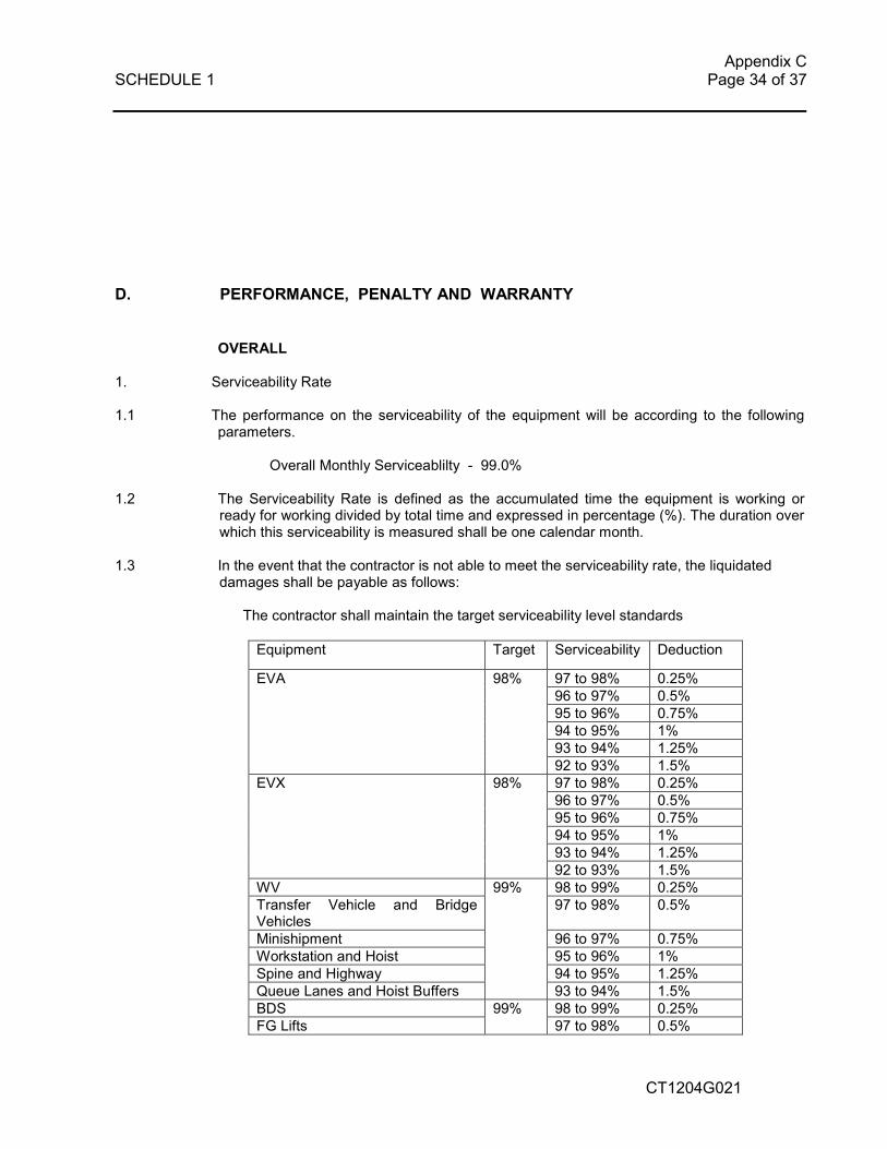
1. Serviceability Rate
1.1 The performance on the serviceability of the equipment will be according to the following
parameters.
Overall Monthly Serviceablilty - 99.0% 1.2 The Serviceability Rate is defined as the accumulated time the equipment is working or
ready for working divided by total time and expressed in percentage (%). The duration over which this serviceability is measured shall be one calendar month.
1.3 In the event that the contractor is not able to meet the serviceability rate, the liquidated
damages shall be payable as follows:
The contractor shall maintain the target serviceability level standards Equipment Target Serviceability Deduction
97 to 98% 0.25% 96 to 97% 0.5% 95 to 96% 0.75% 94 to 95% 1% 93 to 94% 1.25%
EVA 98%
92 to 93% 1.5% 97 to 98% 0.25% 96 to 97% 0.5% 95 to 96% 0.75% 94 to 95% 1% 93 to 94% 1.25%
EVX 98%
92 to 93% 1.5% WV 98 to 99% 0.25% Transfer Vehicle and Bridge Vehicles
97 to 98% 0.5%
Minishipment 96 to 97% 0.75% Workstation and Hoist 95 to 96% 1% Spine and Highway 94 to 95% 1.25% Queue Lanes and Hoist Buffers
99%
93 to 94% 1.5% BDS 98 to 99% 0.25% FG Lifts
99% 97 to 98% 0.5%

Appendix C SCHEDULE 1 Page 35 of 37
CT1204G021
Stacker 96 to 97% 0.75% 95 to 96% 1% 94 to 95% 1.25%
93 to 94% 1.5% The penalty for not meeting the above will be 0.25% of the contract cost for each percentage point below the serviceability level standard up to a maximum 1.5% of the total contract cost.
1.4 If the serviceability targets are not met for more then three months, it will be grounds for termiantion of the contract.
2.1 Preventive Maintenance
a. Adherence to PM schedule
If the contactor fails to start the PM on an equipment on time, SAS willl be entitle to claim $50 for each incident. If the PM is not completed on time SAS will claim $50 per incident. If any PM is postphoned due to contractor request, it must be completed within one subject to availability as confirmed by SAS.
b. Maximum spares usage during PM shall be $3000 per month. SAS approval must
be sought for any change of spare parts.
2.2 First Line Maintenance
a. The expected response time to reach site when activated and the contractors staff is available and not attending to any breakdowns shall be 10 mins.
If the response time failure per month exceeds more then three times per shift as confirmed and endorsed by the contractors supervisor and SAS a penalty of $50 will be imposed.
b. The number for men required per shift shall be three ie 3 men at all times. . c. The Contractor is required to have sufficient men for first line maintenance support
so that the men can be rotated for duty. If any men (as rostered) do not report for work, liquidated damages of $200 per shift per man will be imposed.
d. If the contractors men are late by more than 1 hr, liquidated damages of $50 will be
imposed.
2.3 Repeated LDs
If the same LDs are imposed for two months consecutively the LD quantum will be increase by 25% and increase by 25% every successive month the same LD is imposed until the contractor has improved his service level. eg First month $50 Second month 1.25x50 = $62.5 Third month 1.5x50 = $75

Appendix C SCHEDULE 1 Page 36 of 37
CT1204G021
etc If the contractor again fails the same SLA the LD quantum will keep on increasing y 25% Ie First month $50 Second month 1.25x50 = $62.50 Third month 0
Fourth month 1.5x50 = $75 3. WARRANTY
3.1 There should not be failure of the equipment within 24 hrs after the equipment servicing,
unless it is due to a failure of a component which SAS has decided not to change. The contractor is required to rectify the fault immediately upon notification at no cost to SAS.
3.2 If the repair job for the repeated failre is performed by SAS, the Contractor shall reimburse SAS for the cost of labour and materials incurred in rectifying the fault through service credits in the form of free repair manhours. The labour cost shall be based on the Contractors manhour rates. All repairs and parts supplied by the contractor if any shall have a 12 month warranty.
4. PERFORMANCE REVIEW 4.1 A montlhy performance review meeting will be conducted. The contractor will need to
prepare the monthly serviceability report including the breakdown to individual equipment type. They will also need to identify the top ten recurring breakdowns, top ten breakdown which result in long downtime and the top five contributing faults which result in the low serviceability of eachy equipment type.
4.2 Analysis of the reason for the above will be discussed and preventive actions expected. 4.3 This shall not replace the daily briefings and ad hoc meetings that may be arranged.
These can be as often as weekly if there are major problems to resolve.

Appendix C SCHEDULE 1 Page 37 of 37
CT1204G021
E. EXIT PLAN 1. Introduction
The exit plan is required to ensure there is a smooth hand over to the next appointed contractor. A time duration of three months is required to ensure this. The notice starts when the contractor is notified.
2. Handover The contractor will prepare a record of transfer which will be used to document each individual item transferred to the client’s control. The list should be itemised to record all items.
3. Training Training shall be supplied to the new contractor for a period of two months prior to the start
of the new contract with the new contractor. The training shall include work attachment.