Embed Size (px)
Citation preview
A Regulated Incremental Conductance (r-INC) MPPT Algorithm for Photovoltaic System
Thusitha Randima Wellawatta, Young-Tae Seo, Hong-Hee Lee and Sung-Jin Choi
School of Electrical Engineering, University of Ulsan, Ulsan, South Korea [email protected]
Maximum power point tracking techniques play an important role in improving the efficiency of photovoltaic generation system. Among various schemes, the incremental conductance (INC) method is mostly discussed in literature because of its superb tracking ability in irradiance and temperature changes. However, because the conventional INC algorithms adopt a simple duty-cycle updating law that is mainly based on the polarity information of the peak-power evaluation function, it is not possible to maximize the performance in transient as well as steady-state conditions. In order to mitigate above limitations, this paper proposes a novel regulated INC (r-INC) method. Just as a compensator in an automatic control system, it applies a digital filtering to the evaluation function and enhances the power tracking capability. Mathematical modeling of the new MPPT system also has been presented to aid the optimized design process. Comparative test results with a 120W boost peak power tracker verify the superiority of the proposed method over the conventional ones.
Keywords— Solar power generation, Maximum power point trackers, Photovoltaic systems, Linear feedback control systems
I. INTRODUCTION
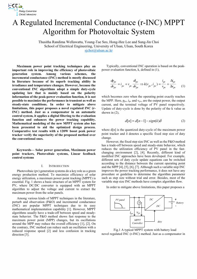
Photovoltaic (pv) generation systems do a key role as a green energy production method. To maximize efficiency of solar energy utilization, a maximum power point tracking (MPPT) is essential. Fig. 1 shows a basic structure of an MPPT system for PV, where DC/DC converter is equipped with an MPPT algorithm to adjust the voltage and current to extract the maximum power from the solar panels.
Among various kinds of MPPT techniques in the literature, perturb and observation (P&O) and incremental conductance (INC) are popular MPPT techniques due to its easy mathematical implementation capability [1]. However, MPPT algorithms usually have a trade-off between speed and steady-state behavior. The P&O method shows fast response to the maximum power point (MPP) changes, but its oscillations around the MPP may reduce the overall efficiency [1], [2]. On the contrary, INC method can reduce such an oscillation with a reduced response speed [2] and less confusion in tracking direction [3].
Typically, conventional INC operation is based on the peak-power evaluation function, k, defined in (1),
( , )
pv pv pv pv
pv pv pv pvpv pv pv pv
dp di i ii v k v i
dv dv v v
Δ= + = + Δ (1)
which becomes zero when the operating point exactly reaches the MPP. Here, ppv, ipv and vpv, are the output power, the output current, and the terminal voltage of PV panel respectively. Update of duty-cycle is done by the polarity of the k value as shown in (2),
δ)(]1[][ ksignndnd −−= (2)
where d[n] is the quantized duty-cycle of the maximum power point tracker and δ denotes a specific fixed step size of duty change.
However, the fixed step size INC as well as the P&O method has a trade-off between speed and steady-state behavior, which reduces the utilization efficiency of PV panel in the fast-changing environment [2], [4]. Recently, different kind of modified INC approaches have been developed. For example, different sets of duty cycle update equations can be switched according to the distance between the current operating point and the MPP [4], [5], [6], [7]. Although such a variable step INC improves the power tracking performance, it does not have any procedure or guideline to determine the algorithm parameter such as step size without trial and error. Besides, most of the variable step size INC methods have complex algorithm flow.
In order to mitigate above limitations, this paper proposes a
PV panel DC
DCBattery
MPPTController
V
ipv vpv
duty
-
+
Fig.1 A typical MPPT system with battery load
novel regulated INC (r-INC) method. Just as a compensator in
an automatic control system, it utilizes the delayed error information of the evaluation function and enhances the power tracking capability. A systematic design procedure for the algorithm parameters also has been presented with mathematical modeling and controller design.
II. PROPOSED METHOD
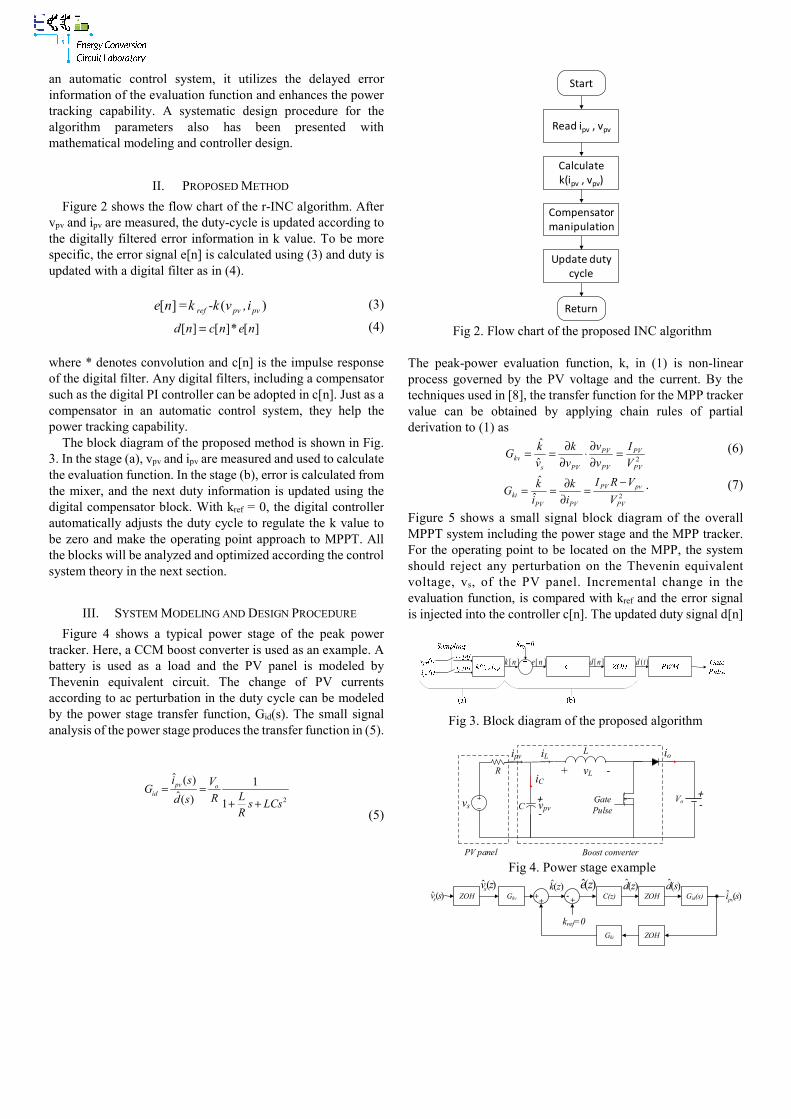
Figure 2 shows the flow chart of the r-INC algorithm. After vpv and ipv are measured, the duty-cycle is updated according to the digitally filtered error information in k value. To be more specific, the error signal e[n] is calculated using (3) and duty is updated with a digital filter as in (4).
i,v-k=kne pvpvref )(][ (3)
[ ] [ ]* [ ]d n c n e n= (4)
where * denotes convolution and c[n] is the impulse response of the digital filter. Any digital filters, including a compensator such as the digital PI controller can be adopted in c[n]. Just as a compensator in an automatic control system, they help the power tracking capability.
The block diagram of the proposed method is shown in Fig. 3. In the stage (a), vpv and ipv are measured and used to calculate the evaluation function. In the stage (b), error is calculated from the mixer, and the next duty information is updated using the digital compensator block. With kref = 0, the digital controller automatically adjusts the duty cycle to regulate the k value to be zero and make the operating point approach to MPPT. All the blocks will be analyzed and optimized according the control system theory in the next section.
III. SYSTEM MODELING AND DESIGN PROCEDURE
Figure 4 shows a typical power stage of the peak power tracker. Here, a CCM boost converter is used as an example. A battery is used as a load and the PV panel is modeled by Thevenin equivalent circuit. The change of PV currents according to ac perturbation in the duty cycle can be modeled by the power stage transfer function, Gid(s). The small signal analysis of the power stage produces the transfer function in (5).
2
ˆ ( ) 1ˆ( ) 1
pv oid
i s VG
LRd s s LCsR
= =+ +
(5)
Fig 2. Flow chart of the proposed INC algorithm
The peak-power evaluation function, k, in (1) is non-linear process governed by the PV voltage and the current. By the techniques used in [8], the transfer function for the MPP tracker value can be obtained by applying chain rules of partial derivation to (1) as
2ˆ
ˆ
PV
PV
PV
PV
PVskv V
I
v
v
v
k
v
kG =
∂∂⋅
∂∂== (6)
2ˆ
ˆ
PV
pvPV
PVPVki V
VRI
i
k
i
kG
−=
∂∂== . (7)
Figure 5 shows a small signal block diagram of the overall MPPT system including the power stage and the MPP tracker. For the operating point to be located on the MPP, the system should reject any perturbation on the Thevenin equivalent voltage, vs, of the PV panel. Incremental change in the evaluation function, is compared with kref and the error signal is injected into the controller c[n]. The updated duty signal d[n]
][nk ][ne ][nd )(td
Fig 3. Block diagram of the proposed algorithm
vs
R
L
C vpv
+ vL -
ipv iL io
iC
+-Vo+
-
PV panel Boost converter
Gate Pulse
Fig 4. Power stage example
Gid(s)ZOHC(z)- . +Gkv
Gki
)(ˆ svs )(ˆ sipv
)(ˆ zk )(ˆ zd )(ˆ sd+ . +
kref=0
)(zeZOH
ZOH
)(ˆ zvs
Start
Read ipv , vpv
Calculate k(ipv , vpv)
Compensator manipulation
Update duty cycle
Return

Fig 5. Overall small signal block diagram
(a) Root locus and Bode plot of C(s)
(b) Step response to kref
Fig 6. Compensator design
generates a continuous duty-cycle by error signal. By automatic control theory such as block reduction techniques and root locus positioning, digital controller design can be performed to maximize the MPPT performance.
To check the feasibility of the proposed scheme, schematic of PSIM simulation is implemented as in Fig. 7. Specification of a PV module and the power stage parameters are shown in Table 1. After, an analog PID compensator C(s) has been designed using MATLAB sisotool as shown in Fig.6, the digital MPPT compensator C(z) has been obtained by s-to-z domain transformation. Thus C(z), in (8) is calculated to be a 2nd order z-transform function and its coefficients are also shown in Table 1. While the steady-state tracking performance of the
(a) Power stage
(b) Compensator based INC MPPT system Fig 7. PSIM simulation schematic
system is determined by measuring the MPPT efficiency using the formula in (9) according to the EN50530 standard [9], the transient responses are measured by power output undershoot and 1% settling time in response to the step irradiance changes. The integration time in the efficiency formula is taken as Tm.
1 2
0 1 21 2
1 2
( )1
b b z b zC z
a z a z
− −
− −
+ +=+ +
(8)
Table 1: Simulation parameter
Category Parameter Value
PV panel BP MSX 120
Pmax 120W Vmpp 33.7V
Impp 3.56A
Voc 42.1V
Isc 3.87A
Shunt res. 1000Ω
Series res. 0.0015 Ω
Power circuit
C 22uF
L 56uH
Vo 48V
fsw 100kHz
Controller C(z)
fs 10kHz
b0 0.1541
b1 -0.1262
b2 0.0221
a1 -1
a2 0

=m
m
T mpp
T sense
dtP
dtPη (9)
IV. SIMULATION RESULTS
For further verifications, the proposed method has been
compared with the two previous schemes – P&O and fixed step INC– and simulation results are shown in Fig. 8. Note that all

curves are plotted in power (W) vs. time (sec). Simulation has been performed between 200 and 1000W/m2 insolation and 20oC temperature with 0.1msec sampling time. The MPPT efficiency has been measured as a moving average. Here, Pmax denotes the maximum achievable output power from the PV panel and Psense represents the instantaneous output power from the PV panel. Some critical changes of simulation waveforms are magnified and marked as A, B, C, and D in Fig. 8, respectively. The magnifications of individual figures are made at below instants.
A – 1000 to 200 W/m2 step changes of insolation. B – Constant insolation (200 W/m2) start to increase linearly. C – Peak of the sinusoidal insolation (1000 W/m2). D – Minimum of the sinusoidal insolation (200 W/m2). E – 20 to 30oC temperature step change with 1000 W/m2 constant insolation.
The error in the output power, (Pmax - Psense) is indicated by
Perror. In the tests of the conventional algorithms, voltage perturbation size of the P&O and duty-cycle resolution for the fixed step INC had been set to 0.006 V and 0.01, respectively. In simulation results, the undershoot and settling time is observed in 1000 to 200 W/m2 step changes (magnification “A”). The average power oscillations at MPP is obtained by averaging the Perror.
According to results in Table 2, the lowest undershoot is achieved by the proposed algorithm. Although the settling time becomes a little bit longer than before, the power oscillation around the MPP is substantially reduced and thus efficiency is improved. These results reflect that the proposed digitally compensated INC shows comparatively better performance than the conventional methods.
V. CONCLUSION
In this paper, we proposed a new digital filter-based INC algorithm. In this method, a PID digital controller automatically adjusts the duty cycle to regulate the evaluation function to be zero and make the operating point approach to MPPT. The new MPPT algorithm has been compared with the P&O and the fixed step INC in a PSIM simulation as well as hardware setups. According to the comparison results, the proposed method has improved performance in transient response as well as the steady state MPPT efficiency.
REFERENCES [1] D. Sera, L. Mathe, T. Kerekes, S. V. Spataru, and R. Teodorescu, On the
Perturb-and-Observe and Incremental Conductance MPPT Methods for PV Systems, “IEEE Journal of Photovoltaics,” Vol. 3, No. 3, pp. 1070–1078, July 2013.
[2] N.E. Zakzouk, M.A. Elsaharty, A.K. Abdelsalam, A.A. Helal, and B.W. Williams, “Improved performance low-cost incremental conductance PV MPPT technique,” IET Renewable Power Generation, Vol. 10, No. 4, pp. 561–574, 2016.
[3] M.A. Elgendy, B. Zahawi, and D.J. Atkinson, "Assessment of the Incremental Conductance Maximum Power Point Tracking Algorithm," IEEE Transactions on Sustainable Energy, vol. 4, no. 1, pp. 108-117, Jan. 2013.
[4] Y.T. Chen, Z.H. Lai, and R.H. Liang, “A Novel Auto-scaling Variable Step-size MPPT Method for a PV System,” Solar Energy, Vol.102, pp. 247–256, 2014.
[5] F. Liu, S. Duan, F. Liu, B. Liu, and Y. Kang, "A Variable Step Size INC MPPT Method for PV Systems," IEEE Transactions on Industrial Electronics,” Vol. 55, no. 7, pp.2622-2628, July 2008.
[6] Y. Tian, B. Xia, Z. Xu, and W. Sun, "Modified Asymmetrical Variable Step Size Incremental Conductance Maximum Power Point Tracking Method for Photovoltaic Systems", Journal of Power Electronics, Vol. 14, No. 1, pp. 156-164, Jan. 2014.
[7] Q. Mei, M. Shan, L. Liu, and J.M. Guerrero, “A Novel Improved Variable Step-Size Incremental-Resistance MPPT Method for PV Systems,” IEEE Trans. on Industrial Electronics, vol. 58, no. 6, pp. 2427- 2434, June 2011.
[8] E. M. Ahmed, M. Shoyama, “Stability study of variable step size incremental conductance/impedance MPPT for PV systems”, Proceedings of 8th International Conference on Power Electronics (ICPE 2011) - ECCE Asia, May-Jun. 2011.
[9] EN 50530, Overall Efficiency of Grid Connected Photovoltaic Inverters, BSI, 2013.
Table 2: comparison of system performance
Condition MPPT method Undershoot
(% PPV)
1%
Settling time (s)
Avg. power oscillations
at MPP (W)
MPPT efficiency η
(%)
Irradiance 1000→200W/m2
200C Tm =0.3s
P&O 13.54 0.0009 0.1732 99.77
Fixed step INC 23.56 0.0007 0.2651 99.65
Proposed INC 11.92 0.0013 0.1032 99.87