Embed Size (px)
Citation preview

RP256
A REDETERMINATION OF THE CONSTANT OFGRAVITATION
By Paul R. Heyl
ABSTRACTA redetermination of the constant of gravitation has boon made using the
torsion balance in vacuo. The large masses were steel cylinders weighing about66 kg, and the small masses spheres of gold, platinum, and optical glassfinal result obtained is 6.670 X10"8 cm3 g" 1 sec."2
.
While the results obtained appeared to differ slightly with small balls of gold,platinum, or glass, it was shown by a special experiment with the form of torsionbalance used by Eotvos that this is not to be attributed to difference in material.
CONTENTSPage
I. Introduction 12441. The nature of the constant of gravitation 12442. Summary of earlier measurements 12453. Work of Boys 12454. Work of Braun 12465. Organization of the present work L247
II. Plan of method 1247III. Description of apparatus 1248
1. Observation room 12482. The large masses 12493. The supporting system 12504. The small masses 1251
5. The moving system 12526. The container 12547. The optical system 12558. Measurements of time 1256
9. Measurements of length 1258IV. Mathematical theory 1257
1. The attraction of a finite cylinder at any external point 1257
2. Formula for time of swing 1 269
V. Method of observing 1275
1. Centering adjustments 1275
2. Length measurements 1277
(a) Horizontal 1277
(6) Vertical 1279
3. Time measurementsJ279
VI. Computations ' -s-
VII. Results1. Gold balls
2. Platinum balls £84
3. Glass balls - v »
4. Mean value - s\'
5. Discussion of results - V,
J
VIII. The specific attraction of platinum and glass ->.
IX. Summary and general conclusions - WW1243

1244 Bureau of Standards Journal of Research ivoi.s
I. INTRODUCTION
1. THE NATURE OF THE CONSTANT OF GRAVITATION
The constant of gravitation is the multiplying factor G in the
formula
F=G^ (1)
giving the force F of gravitational attraction between two masses Mand m, with a distance d between their centers of attraction.
This constant of nature is one of the few that best deserve the
name. It is known to be independent of the nature of the attracting
materials to a precision of 6 parts in 10. 1 It is known to be inde-
pendent of the temperature to a precision of about 1 part in 10,000. 2
It appears also to be unaffected by the presence of different materials
in the space between the attracting bodies. 3
In theoretical importance the constant of gravitation ranks withthe velocity of light and Planck's constant of action. In Einstein's
theory of gravitation it appears in a formula for the curvature of
space due to the density of distribution of matter.4 It undoubtedlyhas some intimate connection not yet understood with the ultimatestructure of the universe.
Practically this constant is of importance as it enables us to de-termine the mean density of the sun and of the other planets of thesolar system.
In thus applying the constant of gravitation it should be pointedout that we are making an assumption—that this constant is thesame between the earth and the sun as between two bodies on theearth's surface. The arbitrary nature of this assumption becomesclear when, following Einstein, we regard gravitation as due to spacecurvature arising from the presence of matter. We are, in fact,assuming space to be everywhere equally resistant to deformation.We do know that the constant of gravitation is approximately thesame at several points on the earth's surface, and there is no. reasonto suspect the contrary; but we do not know that the same will holdtrue for different radii, as between the earth and the moon, or evenbetween the center and the surface of the earth.But if we are wrong in this assumption it is of little practical im-
portance. Our estimates of the masses of the heavenly bodies mightbe in error, yet their mutual attractions and relative motions wouldstill be the same. However, in the case of a body moving in a verytone elliptical orbit, such as a periodic comet, there might be a smalldifferential perturbation from this cause.And we are not entirely without evidence that our estimate of the
mass oi the sun, at least, is not grossly erroneous. The Einsteins nit of the lines m the solar spectrum depends on the solar mass.\\ bile experimental evidence on this point is not of the highest pre-cision, it is perhaps safe to say that our estimate of the mass of thesun is not in error by as much as 20 per cent
iE^w>^X^^'^-^ 1922-
' '« Wn, Blteungsbertchta dor Preiiaa, Akad.'d. w'iss.; Feb. 8, 1917.

He^ Constant of Gravitation 1 245
2. SUMMARY OF EARLIER MEASUREMENTSAn excellent summary of experimental work on the constant of
gravitation may be found in Poynting's article "Gravitation" in theEncyclopaedia Bntannica (11th ed.). To this is to he added a ref-erence to the work of Cremieu (Comptes rendus, vol. in V]) 653713; 1905, and vol. 149, p. 700; 1909)
J'
'
The value accepted for this constant for the last 30 fears baa restedupon the independent work of Boys and of Braun.8 These twoexperimenters obtained results agreeing to 4 significant Bguree6.658 X10-s cm3 g- 1 sec.- 2
, but because then individual values vaiieAm the third figure (by as much as 4 units in Braun's work and by2 units in that of Boys) Poynting, in his discussion of the subject,adopts the value 6.66 X10⁻⁸
, subject to an uncertainty of 1 umf inthe third figure.
3. WORK OF BOYS
Because of the importance of the work of Boys and of' Braun it
will be well to consider their experiments in more detail. Bo! h usedthe torsion balance, which has been employed in one form or anotherby half a dozen different experimenters since the days of Cavendi-h,but each employed a different arrangement.
Boys, guided by theoretical considerations which show that a shortbeam may, under certain conditions, give increased sensitivity,
constructed his apparatus so that the horizontal distance betweencenters of the small masses was 1 inch and that between centers of
the large masses 6 inches. Since with centers of all masses at thesame level the proximity of a large mass to both small ones wouldlargely wipe out the increased sensitivity arising from the short
beam, Boys arranged the masses in pairs, one large and one small
mass in each pair, the two pairs being at different levels.
The large masses used by Boys weighed about 7.4 kg each and the
small masses each about 2.65 g.
Boys did not use a vacuum in his apparatus; in fact, he stated in
his published paper (p. 70) that he was sure the use of a high vacuumwas out of the question. He did, however, carry out one experiment
with a hydrogen-filled apparatus, but the results were not encourag-
ing. In fact, no experimenter previous to Braun had made any
attempt to work at reduced pressure, and all had experienced trouble
from convection currents. Boys was forced to go to great lengths
in the way of screens and heat insulation in the attempt to eliminate
this difficultv.
Of the two methods of using the torsion balance, direct deflection
and time of swing, Boys used the first only. In this method the
large masses are set in a position of maximum attraction on t In-
moving system, (a, a, fig. 1.) After determining the resting point
the moving system then takes up, the large masses are moved to a
similar position with opposite turning effect (b, 6), and the resting
point again noted. Half the angle between the two positions ol the
moving system measures the deflection produced hv the mutual
attraction of the masses.
Boys aimed at a precision of 1 part in 10,000, and so designed his
apparatus as to afford the accuracy theoretically necessary to attain
• C. V. Boys, Phil. Trans. Roy. Soc. A Pt. 1 p. 1; 1895. Carl Braun, Denkschriften der k. Aka.l. -i
Wiss. (Wien), math. u. naturwiss. Classe, 64, p, loi, USJ<.

1246 Bureau of Standards Journal of Research ivoi.s
this end. -His final results, however, fell considerably short of this
precision. Omitting the experiment with the hydrogen-filled appara-
tus, he obtained the following nine results (omitting a fifth figure
given by Boys)
:
6.665 XIO"8 6.658 X 10~8
6.670 X10"8 6.653 XIO"8
6.671 XIO"8 6.658 X 1(T8
6.668 X10⁻⁸ 6.670 XIO"8
6.655 XIO"8
The mean of these values, assumed of equal weight, is 6.663, with
an extreme variation of 0.018 and an average departure from themean of 0.006. Boys remarks,
Ob f*} CUhowever, that conditions of dis-
v^ turbance varied greatly in thedifferent experiments, and heselected the fifth, sixth, sev-
enth, and eighth of the aboveseries as being most likely to
give a true value. Moreover,he seems to have assignednearly all the weight to thesixth and eighth, adopting ashis final figure 6.658 X 10"8
.
a-— ^;^- <:!" o4. WORK OF BRAUN
^ Braun used a torsion bal-
ance of larger dimensions thanthat constructed by Boys, thedistance between centers of
the small masses being about25 cm and that betweencenters of the large massesabout 42 cm. The large
f"} a ("*) (> masses weighed about 9 kg^-^ ^^ each and the small masses eachFigure 1.—Direct deflection method about 54 g. His apparatus
was arranged in the usualway, with the centers of all four masses at the same level. For along beam there is little objection to this plan.Braun was the first to perform this experiment at reduced pressure,
part of his results being obtained at 16 mm Hg and part at 4 mm Hg.Braun used both the direct deflection and the time-of-swing
methods. In the latter method the time of swing is measured withthe large masses in two positions which may be called "near" andfar. (Fig. 2.) A little study of this figure will show that in the
near position the attraction of the large masses upon the moving sys-tem is such as to accelerate the swing, while in the far position itretards it With the masses and dimensions used by Braun thedifference between the two times of swing was about 46 seconds.
Hrnun stated his results in terms of the mean density of the earthratner than of the constant of gravitation. He published results

Heyi] Constant of Gravitation 1247
of 46 separate experiments, 26 by the time-of-swing method and 20-by the method of direct deflection, the individual results beingweighted from 1 to 4. The individual results vary by as much as 4
units of the third significant figure.
5. ORGANIZATION OF THE PRESENT WORK
So well done was the work of Boys and Braun that the difficulty
of improving upon it was clearly recognized. Such a task requires
the resources of an institution rather
than of an individual. Practically /"s ^ S~*\
-every division in theBureau of Stand- \s J O""" vj {^)
,ards has contributed tangibly or in-
tangibly to the successful completion NEARof this experiment. The work wouldprobably not have been undertakenhad it not been for the encourage-
ment of the director, Dr. George K.* Burgess, whose interest in the sub-
ject dates back to his student days,
and for the like encouragement of
Dr. L. J. Briggs, chief of the division
of mechanics and sound, whose in-
terest in gravity measurements at
sea is well known. ^ms^
The completion of the undertak- Q ^ing in a reasonable time has been v-'
made possible by the cooperation of
E. R. Frisby, who has done about
90 per cent of the very laborious com-
putations and, in addition, worked
out the formulas for the time of swing. Q ODrs. H. L. Dryden, of the Bureau
of Standards, and E. W. Woolard, of
\ George Washington University, have1 rendered valuable services in check-
ing the mathematical work at differ- —
.
ent stages. I)The apparatus was constructed ^-^
almost entirely in the Bureau of PARStandards instrument shops by J. F. r n r\
Draper The task required nearly Figure 2 —Time of swing met/
e
a
dirnt
f
ilS^, hettrsiestions offered by Mr. Draper in
the course of the work.
II. PLAN OF METHOD
A studv of the work of Boys and Braun led to the conclusion thai
litttetat to be hoped for in the way of h^JJES^

1248 Bureau of Standards Journal of Research [vol.
5
done, for in Braun's experiments this objection does not hold, yet
his result by the direct-deflection method confirms that of Boys.
With the time-of-swing method the case is different. Braun says
in his published paper that the possibilities of this method muchexceed those of the other, and expresses his regret that he was unable
to make full use of them. It was therefore decided to use this
method only in the repetition of the experiment.
Of the two arrangements of the torsion balance Braun's form seemedpreferable to that of Boys for two reasons—it is easier to obtain
precision in the important measurement of the horizontal distance
between centers of the small masses when this distance is large; and
it was planned to increase greatly the size of the large masses, whichwould have made a very considerable difference of level necessary.
The general dimensions of Braun's apparatus, apart from the size
of the large masses, seemed ample for obtaining a precision of per-
haps 1 part in 10,000. The apparatus was, therefore, designed after
the general pattern of that used by Braun, with a considerable increase
in the large masses.
Three series of measurements were made, using small masses of
gold, platinum, and optical glass.
Photographic recording of the time of swing was considered, anda special form of moving film camera was constructed for this pur-pose; but it was found that with the distance to be traveled by thebeam of light (about 7 m) and the passage through 8 pieces of glass
with 2 reflections, it was difficult to obtain an image bright enoughto be photographed in motion and at the same time sharp enoughto be acciirate. It was easily possible to obtain a sharp image suffi-
ciently bright for visual observation, and it was therefore decided tomake the observations visually, and to record them by a chronograph.
III. DESCRIPTION OF APPARATUS1. OBSERVATION ROOM
As an observation room there was available the constant-temper-ature vault of the bureau, divided into two rooms, one large and onesmall. This vault is located below the East Building at a depth ofabout 12 m below ground. In addition to furnishing uniformtemperature this depth eliminated any trouble that might other-wise have arisen from moving masses near by.The torsion pendulum was set up in the small room, the floor
space of which was about 2 X 2.7 m and the height about 4 m. Theobserving apparatus was placed in the large room, the interveningbrick wall being pierced by a window about 30 cm square. A pierwas built in each room, in the small room at its center, and in thelarge room close to the far wall, the distance between centers of piersbeing about 3.5 m. At this distance calculation shows that thecllcct ol the observer's mass upon the moving system is less thanone ten-thousandth that of the two large masses. It was deemedadvisable, however, that the observer remain in the same place dur-ing the whole period of observations, rising from his chair whennecessary to attend to the chronograph at his side, but not movinghorizontally from his location.

Tleyl] Constant of Gravitation L249
The observation room proved ideal for the purpose. No vibrationwas observable, and it was possible to work bv dav with resultsequally as good, as those obtained by nierbt. Practically nil thewrork was therefore done by day.
2. THE LARGE MASSES
When it is a question of dealing with large masses in an experiment.of this kind the nature of the material becomes important, Caven-dish (and later Baily) used spheres of lead weighing nearly L60 kg.Such large masses of lead or lead alloy can hardly be trusted to main-tain their shape accurately over long periods of time. In addition,there is always the possibility of holes in the casting. To avoid thislatter difficulty several experimenters (Braun among the number).have used hollow spheres filled with mercury.
For the present work it seemed most practicable to employ steel,because of ease of accurate shaping and permanence of form. Toolsteel of about 0.90 per cent carbon was selected as being most uni-form in structure and least liable to segregation. To avoid blow-iholes and pipes a large ingot of 30 cm diameter was forged downto 20 cm and annealed for machining. This work was done at the.Washington Navy Yard.
Nearly all previous experimenters have used masses of sphericalform because of the simplicity of the calculations involved. Thepractical difficulties incident to the accurate machining of a sphereof the weight planned (over 60 kg), especially in cutting off androunding the ends, as well as the difficulty of determining accurately
the center of the sphere when mounted in place, appeared so great
that it was decided to adopt a cylindrical form, thus shifting the
burden to the broad shoulders of the mathematician.After machining the cylinders to size, their dimensions and masses
were determined, respectively, by Mr. Miller and Mr. Peffer, of the
weights and measures division. These results, in grams and centi-
meters at 20° C, are given in Table 1.
Table 1.
—
Dimensions and masses of cylinders
Cylinder mark
-
Diameter (extreme variation)f 19.4514
\ 19. 455219. 4534
/ 28. 4974
\ 28. 501228.5007
66, 302. 6
19. 472719. 47.58
19. 4743
28. 480428.485226. 4827
66, 401. G
When in place in the apparatus the cylinders are surrounded by air,
/and the attraction of a cylinder at any point will be that due to the
mass of the cylinder in vacuum minus the mass of the displaced air
jWe may consider a cylinder of this slightly reduced mass superposed
iupon a continuous and uniform distribution of air. The air being
i infinite and continuous exerts no resultant attraction at any point
/within it, and the total resultant attraction is therefore that due to

1250 Bureau of Standards Journal of Research [Vol.
the superposed cylinder. Thus the effective values of the mass and
density of the cylinder will be found by correcting for displaced air at
the temperature, pressure, and humidity existing at the time of the
experiment.. . ..
Calculation shows that for a variation in relative humidity from
57 to 86 and for the usual pressure variation the mass of air displaced
by a cylinder is constant to the first decimal place, namely, 9.9 g; and
this is also the precision to which'the masses of the cylinders are known.Applying this correction to the values given in Table 1 we obtain the
effective values given in Table 2
:
Table 2.
—
Effective masses and densities of cylinders
Cylinder mark
-
66, 292. 7
7. 8258366, 394. 7
7. 82608
Uniformity of density is an important consideration. There canhardly be any question of appreciable pipes or blowholes after thepreliminary reduction by forging, but we must consider the possibility
that by this forging the outer layers of the cylinder may have beenmade slightly denser than the center. Segregation also might cause achange in density of like distribution. As a check upon this, sampleswere taken from the bosses cut off from an end of each cylinder in thefinal stages of machining, and the density of these samples determined.Each sample had a diameter of about one-fifth that of the cylinder,and may thus be taken as representing approximately the density ofthe cylinder near its axis. Table 3 shows the comparison of thesedensities with the calculated values for the whole cylinders.
Table 3.
—
Variation in density of cylinders (in vacuum)
Cylinder mark
-
Density near axis. 7. 82557. 8270
7. 82507. 8273Calculated mean density
In no case is there a difference in density greater than about 1 partin 4,000. An approximate calculation shows that the error intro-duced in the value of the attraction by the assumption (for instance)of a uniform density of 7.8273 instead of one varying uniformly from7.8250 at the center to 7.8285 at the outer surface (with a mean of7.8273) amounts to less than 1 part in 50,000, negligible for presentpurposes.
3. SUPPORTING SYSTEMThe large masses were supported so as to be free to turn in azimuth
about a vertical axis midway between them. The general arrange-ment is shown in Figure 3

B. S. Journal of Research. RP256
Figure 3.—General arrangement of apparatui

n*vi] Constant of Gravitation1 25 1
Two 15 cm I beams wore set into the brick walls of the room with aspace of about 20 cm between them. Across these beams w as fastenedby screw clamps a steel plate 2.5 cm thick and L5 cm wide. Thiscrosspiece was pierced at the center by a hole 3.7 cm in diameterthrough which passed by a snug fit the vortical axis of the supportingsystem.
This vertical axis was capped at the upper end by a disk restingupon a ring of steel balls rolling in a channel cut in the crosspiiFastened to the upper surface of the desk was a graduated circLcm in diameter provided with a vernier reading to 0.1°.
The vertical axis carried at its lower end an arrangement of dove-tailed blocks allowing two sliding adjustments at right angles, for thepurpose of centering the cylinders with respect to the point of Bupportof the pendulum.
Fastened to the lowest of these sliding blocks was the crossbeamB (fig. 3), from the ends of which hung the cylinders .1, A. Bachcylinder was supported by three steel rods, 0.5 cm in diameter, screwedinto the cylinder by tapped holes, each hole threaded all the waydown to a flat bottom against which the flat end of the rod fitted.
Each rod was provided with a lock nut where it entered the cylinderand, near its upper end, with a turnbuckle by which the cylinder
could be leveled. The vertical adjustment of the cylinder as a wholecould be secured by raising or lowering a disk from which the three
rods hung. Each disk was supported by a bolt and nut passing
through a slot in the crossbeam B, thus permitting separate horizontal
adjustments of the cylinders.
4. THE SMALL MASSES
Small masses, spherical in shape, were used of three different
materials, gold, platinum, and optical glass. In each case the mass
was about 50 g.
This use of different materials was not prompted by any suspicion
that a specific difference in attraction might be found. Rather was
it the result of circumstances. The use of gold balls was suggested by
the employment of this metal by Boys and by the fact that Braun
used gilded balls of brass. There was no objection to this in the case
of the work of Boys, who did not employ a vacuum, and Braun men-
tions no trouble with his gilded balls; but in the present work it was
found on opening the container, after a period of several months
reouired for the observations, that the gold balls had absorbed quite
appreciable quantities of mercury, probably derived m vapor form
from the manometer connected to the container.
A second set of measurements was made with platinum halls, co»\->a
I
thinly with lacquer by dipping. No appreciable change ot weight
| was observed in this case.
A third set was made with balls of optical glass, the idea being that
holes in the interior could be detected visually.
The metallic balls were constructed from ingots which (in the case
I of gold) had been fused in a vacuum furnace to avoid eas bubbles.
The platinum ingots were fused in the oxvhvdrogeii ffame in foe
usual manner. The ingots were first rc,.i-lily h».inm-n,l into shane
, between hemispherical steel dies, as described by Boys, and t. nails
18296°—30 5

1252 Bureau of Standards Journal of Research [Vol. 6
shaped to size by a scraping process suggested by J. F. Draper, of the
bureau's instrument shops.# ,,,/',-,.
In a piece of thin sheet steel was cut a circular hole ol the diameter
desired for the finished sphere. The ball, after having been hammered
to a diameter but little in excess of the final size, was laid in this hole
and turned this way and that between the thumb and finger until it
had scraped its way through the hole. In the case of the platinum
balls this operation was conducted under water. The resulting balls
were so nearly spherical that micrometer measurements (to about
2.5 ju) could detect no variation in diameter.
In each metallic ball there was drilled a hole 1 mm in diameter and
3 mm deep, which was threaded. A piece of copper wire 6 mm long,
threaded for half its length, was screwed into the hole. The proj ecting
portion of the wire was shaped into a hook.
The glass balls were drilled with holes 1 mm in diameter and 4 mmdeep, the lower part of the whole being enlarged to a diameter of 2
mm by a dental burr. Inthis hole was inserted a dou-bled piece of copper wire,
loop downward. The spacebetween wire and glass waspacked with small scraps of
tin foil after the manner of
filling a tooth, using a bluntedneedle and fight taps from asmall hammer. The tinfoil
packing was stopped abouthalf a millimeter from thetop of the hole and the rest
of the space filled with wax.The protruding ends of thewire were joined by a trace
of solder and bent into a hook.In each case the mass of
a ball was determined beforedrilling it. At the conclu-sion of a set of measurementsthe ball was cut from the
Figure 4.
—
The moving system
suspending filament close to the hook, and reweighed with hook, knotof filament, and trace of wax used to keep the knot from slipping.The slight excess of mass over that of the solid ball was regarded forpurposes of calculation as a massive point added at the north pole ofthe ball.
5. THE MOVING SYSTEM
The moving system, or torsion pendulum, consisted of the twoI niMsscs, a light separating rod and the necessary supporting
filaments. (Fig. 4.) In the design of this system the object was tothro* as much as possible of the moment of inertia into the balls sothat the system should approximate a simple pendulum. Actuallyover 99 per cent of the moment of inertia was thus concentrated.
1I'Hioii/.ontal separating rod was of aluminum, 0.24 cm in diameter,
-it .,<) cm Long, and weighted in vacuum 2.4401 2;. Close to each end

Hevl] Constant of Gravitation l'j;,;;
was drilled a small hole through which passed the ends of a cotter winconstituting a truss These ends, after passing through the rod, werebent into hooks The cooper truss wire was 0.36 mm in diameter22.1 cm long and weighed in vacuum 0.2385 g.The balls were hung from a niece of tungsten Lamp filament, 025mm m diameter, tied to their hooks, and laid across the hooks at the
x?dsV
°
fnthe
,
C0PPer trilss ^re. In tying the filament to the hookfl ofthe balls the filament was wrapped four or five times around thehook and the end twisted around the main portion of the filamentI his.twist-was held from slipping by a trace of wax. In cutting offthe balls for the final weighing the twisted portion of the filamentwas included.The supporting filament for the moving system as a whole was also
of tungsten, 0.025 mm in diameter, commercial lamp filament annealedin hydrogen at the factory. Tungsten is preferable to silica in that if
may be confidently relied on for a long program of observations.Filaments of silica, as Boys found, occasionally break for no apparentreason, often with loss of previous observations. Moreover, tungstenmay be tied firmly to the object which it supports.Our experience indicates that tungsten is quite reliable, returning
well to its resting point after large deflections. One such filamentwas in use three years, during which the apparatus experienced I
slight earthquake.The supporting filament was about 1 m long, provided with copper
wire hooks at its ends. By the lower hook the copper truss wirehung at its apex and was fastened by a trace of wax. The upperhook was fastened to a movable torsion head contained in the chimnejof the bell jar. This device (patterned after one used by Braun)consisted of a train of wiieel work, to the slow motion end of whichthe upper hook of the supporting filament was attached. By turningthe other end of the train a very small twist could be given to the fila-
ment to correct, if necessary, for drift of the resting point. In orderto operate this device from outside without breaking the vacuum a
bar magnet was attached to the upper end of the train. P>y the use
of a large horseshoe magnet outside the chimney the requisite t\
could be given.
The train of wheel work was geared to a ratio of 3,000: 1, so thai
one complete turn of the upper end produced a twist of one-tenth i
degree in the filament.
The moving system was provided with a silvered glass mirror, about
2 cm in diameter, 1 mm thick, weighing about 0.0 g, ground and polisl
optically flat. This mirror was attached at its upper edge by a li
wax to a brass rod 1 mm in diameter. At its upper end this bn
rod was provided with a small wire loop by which it was hung from the
lower hook of the main suspension filament. The brass rod, v. here ij
passed the horizontal aluminum rod, was bent into a detour to avoid
contact. (Fig. 4.)
The total mass of the swinging system was about L02g. Liiel i
ing strength of the suspending filament u as about If
To start the moving system gravitational attraction was empl
Two bottles, each holding about 2 kg of mercurj
to the container in positions of maximum attraction tor the penduli
When the latter had been twisted to it - extenl (which n quj
about 15 minutes) the bottles were placed so as to reverse the attl
1254 Bureau of Standards Journal of Research [Vol. s
tion. By repeatedly reversing the positions of the mercury bottles
in time with the swing of the pendulum the latter could be given any
amplitude desired. In two hours time an amplitude of about 4°
could be obtained, which (at the reduced pressure employed) was
sufficient to keep the pendulum swinging for 20 hours.
6. THE CONTAINER
The container was of metal resting on a plate-glass base. Thegeneral shape is shown in Figure 3. The tall chimney was of brass,
open at the upper end, which was closed by a piece of plate glass.
This permitted observation of the magnet connected with the wheel
work. The wide lower portion of the container and the lid fitting it
were, in the series of measurements with the gold balls, of brass wrapped
with thin sheets of silicon steel for magnetic shielding. This arrange-
ment proved cumbersome, and in the measurements^ with platinum
and glass balls this part of the container was made of apiece of wrought-
iron tubing with a lid of the same material. A circular piece of iron
was laid inside the container upon the plate-glass base, thus completing
the magnetic shielding.
This precuation was necessary because of the steel cylinders, whichwhen moved from the near to the far position altered the earth's
magnetic field in the vicinity of the pendulum. Since all materials
are either paramagnetic or diamagnetic to an appreciable degree,
and since the gravitational attraction of a cylinder upon the nearest
ball was only about 0.001 dyne, it is quite possible that the effect of
the change in magnetic field upon the time of swing of the movingsystem might be comparable with that of gravitational attraction.
This suspicion was experimentally confirmed in the case of the brasscontainer used with the gold balls. Before applying the silicon steel
wrapping a bar electromagnet was mounted outside the container withone pole in the maximum attraction position with respect to one of theballs. On energizing the magnet the ball was repelled with an acceler-ation approximately equal to that produced by one of the mercury bot-tles. By raising the magnet to the level of the aluminum rod anattraction was produced. The magnetic susceptibility of gold is
— 0.15 and that of aluminum + 0.65 .
By wrapping the lower part of the container with several layers ofthin silicon steel sheet these disturbances were completely prevented.In the later form of the apparatus, used with platinum and glass balls,the wrought-iron wall of the container was similarly protective.To test the shielding more closely, measurements of time of swing
were made with the outside magnet alternately magnetized and demag-Del Lzed. The magnetic field at the outer surface of the container withthe electromagnet excited was about twelve times as strong as theearths horizontal field, as determined by the rate of vibration of asin mII compass needle. The strength of field close to one of the largesteel cylinders was about three times that of the earth's field, or one-fourth thai used for testing the shielding, and the presence or absenceof the testing field produced no effect upon the time of swing as greatas
1part hi 10,000. Any effect to be expected by moving the cylinders
must therefore be less than 1 part in 40,000.A pressure of about 2 mm of mercury was maintained in the con-
tainer, the joints of which were sealed by soft universal wax. A mer-cury barometric seal was used instead of a stopcock.

Heyl] Constant of Gravitation1 25fi
It may be of interest to record here the effect of pressure upon thedamping exhibited by the moving system. Table* gives the dumpingfactor (ratio of successive amplitudes in the same direction) at \ anouspressures.
Table 4.
Dampingfactor
Pressure,mm mer-
cury
0.70 150.84 50.85 20.85 10
.85 7
.85 5
.86 3
.87 1.5
Windows were provided at strategical points in the container forthe purpose of obtaining such measurements as the level of thecenters of the balls and the position of the filament supporting themoving system.When it was desired to raise the chimney and lid of the container a
yoke was clamped about the upper end of the chimney. From theends of this yoke two threaded rods passed up through holes in thebeam B (fig. 3) and were supported above by nuts. By turningthese nuts the upper portion of the container and the whole movingsystem could be raised or lowered slowly and steadily enough to avoidbreaking the suspension.The temperature of the container was read by means of a ther-
mometer fastened closely in parallel contact with the chimney, the
bulb touching the metal. On its outer side the bulb was shielded bya layer of cotton, the whole being bound to the chimney by strips of
adhesive tape. The temperature inside the container was assumedto be that of the metal case as shown by the thermometer.
7. THE OPTICAL SYSTEM
The basis of reference for observing the time of swing was a scale
of millimeters in the form of a pho-
tographic negative on glass, bright
lines on a dark background. (Fig.
5.) Parallel to the scale and close
to it was a broad bright band against
which could be seen the vertical cross
wire of the observing telescope.
The scale was mounted in a metal
box and illuminated from behind byseveral small electric lamps, and wasset on a pier in the observing room, 3.5 m from the torsion apparatus.
The fight from the scale passed to a reflecting prism below the l:1m<s
base of the container, which reflected it vertically upward, passing
through the iron floor of the container by a hole. The light then
encountered a second prism which reflected it horizontally to the
mirror attached to the moving system. The reflected beam retraced
Figure 5.
—
Scale and cross wire

1256 Bureau of Standards Journal of Research [Voi.s
approximately its entering path and was finally received by a tele-
scope on the observing pier, 3.5 m distant from the center of the mov-ing system. A motion of one minute of arc of the moving system
produced a shift of about 2 mm of the scale in the field of the
jpl psoooe8. MEASUREMENT OF TIME
The working standard of time was a Biefler clock set up in a
constant-temperature vault in another building of the bureau, andrated daily against the Naval Observatory signals. Its usual daily
rate was but a few hundredths of a second. Second signals fromthis clock are electrically transmitted to all parts of the bureaulaboratories.
The transits of the pendulum were recorded on a 2-pen chronograph.
One pen recorded the clock signals and the other the transits of the
scale divisions as observed by the operator.
In making the observations it was customary to adjust the resting
point of the pendulum by means of the torsion head to somewherebetween the twelfth and thirteenth centimeter marks on the scale,
and to record the transit of every millimeter from the eleventh to the
fourteenth centimeter. The calculation of the time of swing will bedescribed in a later section.
9. MEASUREMENTS OF LENGTH
The length measurements fall into two classes—those in whichapproximate values are sufficient and those requiring higher precision.As an example of the first class may be mentioned the vertical differ-
ence of level between centers of balls and cylinders. In the secondclass are found the distance between centers of balls and the distancebetween cylinders.
Measurements of the first class were made to 0.1 mm, mostly witha kathetometer. Measurements of the second class were made withan optical compass similar to that used by Boys; it consisted essen-tially of two micrometer microscopes mounted approximately parallelto each other on a rigid bar. The distance between microscopes couldbe adjusted as desired.A supporting framework of iron was clamped to the pier carrying
the torsion pendulum, and by leveling the optical compass upon thisframework the microscopes could be directed to view any two pointswhose horizontal distance apart might be desired. When the settingof the microscopes had been made the optical compass was placed inanother stand so as to view a scale below it.
This scale was made from a steel bar 2.5 dm square in cross section,provided with several platinum-faced plugs, upon which fine gradua-
|
ions were traced. Sufficient plugs were provided to give the variouslengths required. The scale was calibrated in terms of the standardmeter by Doctor Judson, of the weights and measures division of thebureau.
Steel was used as a basis for the scale rather than invar, as theexperience pi the bureau has been that invar, while low in expansion,snows much hysteresis, and is on the whole less satisfactory for sucha purpose than steel. The coefficient of steel may be higher, but it! more ,.,l,lv bo be counted upon than that of invar.

Ueyl] Constant of Gravitation\
• >- -
IV. MATHEMATICAL THEORY1. THE ATTRACTION OF A FINITE CYLINDER AT ANY EXTERNAL
The use in the Cavendish experiment of attracting bodies of otherthan a spherical shape has been rare. Boys in one of Kperime!
<&Jb
Figure 6.
—
Attraction of finite cylinder at outside point
used cylinders of gold one-fourth inch long and the same in diameter.He states that calculation showed that the attract ion of such ,m cylinderat a point at the center of one of the large balls was Less than that
which would have been exerted had the cylinder been a sphere of equalmass by 3 parts in 10,000. Small masses of cylindrical and also of
chain form were used by P. E. Shaw 6 in his work on a supposedtemperature coefficient of gravitation, but as his work was concernedwith relative rather than absolute values it was not nee
calculate the actual force. Cremieu used large cylindrical mi
but does not mention the computations.
6 P. E. Shaw, Phil. Trans. Roy. Soc, A, 216, 191G.

1258 Bureau of Standards Journal of Research [VoL 5
Calculations for nonspherical masses are not simple; in fact, the
labor involved in making a nonspherical calculation to anything buta rough approximation has rather been looked upon as prohibitive.
For practical reasons earlier mentioned it was desirable to use large
masses of cylindrical form. It was an agreeable surpriseto find that
in the case of the dimensions used it was possible to obtain a formulain zonal harmonics which converged fairly rapidly. Working to 1
part in 100,000 there were necessary only seven terms in the nearposition and six in the far position.
A formula for the attraction of a finite cylinder at any external
point has never, as far as we know, been published. It may therefore
be a convenience to future workers if the development of this formulais given somewhat in detail. The best method of procedure is to
integrate the expression for the attraction of a circular disk. (Fig. 6.)
Byerly 7 gives a formula in zonal harmonics for the potential Vof a circular disk of thickness dx, density p and radius a at any externalpoint whose coordinates are r, 0, the formula being valid if r>a.Formula (2) gives this value of V to eleven terms.
V=2ttpaGdx ^2 r
-i(f)3
p2 (coS 0)
+40)5
i3<(cos0)
-iii©7p
' (COB9)
7 /<zY+256(,rj
P^cosS)
21 f«Y T> , a
~102iW Plo(cose
+2048V7;
Pi2 (cos(>)
429 /a\ 16 „ .
" 32768 (j)P"(°ose)
, 715 /o\ 17 _ .+65536W Pl6fcos0)
2431 /a\ 19
D , „._262144W P>»(C0S V
288^; P.o(cob0)+
; My. rly, Fourier's Series, p. 155, art. 80.

Heyl) Constant of Gravitation L259
Following the notation of Figure 6 in which z is measured positivelydownward from 0, and expressing all variables in (2) in terms of 0,
n 6
a a . n———Sillr c
x = c cot
, cdddx= ——-07,
sin2
and integrating for 6 from B x to 6 2 we obtain:
o?0F= - 2irPacG sin
Kc)Tsind,Pa (c°s0)^
i0Yfsin3 0.P 4 (cos 0)d$
(fj fsin5 0.P 6 (cos 0)dO5
128
+ 2F66)Tsin79 -Ps(cosey9
-iM4G)7sin99 -p '° (cos^^Y
3
fsin 11 0.P 12 (cos 0)d0+33
2048
715
65536
2431
262144
4199
524288
(^Y' fsin 15 0.P 16 (cos 6)dd
(«Y fsin17 0.P i8 (cos0)r/0
^YTsin 19 0.P 2O (cos 9)d6
(3)
(4)

1260 Bureau of Standards Journal of Research [Voi.6
Byerly (p. 151) gives expansions of Pm (x) up to m = 8. Additional
values follow:
1
Pi 2W- 1024
Pu(x]
Pn(x)
2048
32768
Pn(x) = w-z65536
P2o(x)= 1
262144
(46189z10- 109395a:8+ 90090a:6
- 30030a:4+ 3465a;2 -63)
(676039a:12- 1939938a:10 + 2078505a:8
-1021020a:6 + 225225a:4 -18018a:2 X231)
(5014575a:14- 16900975a:12 + 22309287a:10
- 14549535a:8 + 4849845a:6 - 765765a:4
+ 45045a:2 -429)
(300540195x16- 1163381400a:14
+ 1825305300a:12- 1487285800.x10
+ 669278610a:8- 162954792a:6
+ 193.99380a:4- 875160a:2 +6435)
(2268783825a:18- 9917826435a:16
+ 18032411700a:14- 17644617900.x12
4- 10039179150a:10- 3346393050a:8
+ 624660036a:6 - 58198140a:4
+ 2078505a:2- 12155)
(34461632205a:20- 167890003050a:18
+ 347123925225a:16 -396713057400a:14
+ 273491577450a:12- 116454478140a:10
+ 30117537450a:8 -4461857400a:6
+ 334639305.x4- 9699690a;2 + 46189)
Making the necessary substitutions in formula (4) we obtain:
(5)
V=-2irPacGde
sin 9
la fj2 c J si]
lew I
sin ^3 cos2 d~ ^ dd
1 28W Isin" ^35 C°s4 e~ 30 cos2 e * 3^
E§w Jsin8 ^ (231 cos6 6>
~ 315 cos4 *o
2048
4-105 cos2 e-5)de
(6)

Heyl) Constant of Gravitation
V=-2vPacG 32768
21
2(12144
(~JI sitffl •
1201
4 6930 cos4 6 L260co+ 35)d0
(~/j |sin9 0(+(il.sOcos ,o
109395 cos8 6
H 90090 cos6 a 30030 cos4
+ 3465 cos- 0-63)<*0
+33
209715r>(c)
13
fsinU ^G76039 (>os1 *' *
1939938 cos 10
+ 2078505 cos8
-1021020 cos6
4- 225225 cos4
-lSO18cos2 + 231)</0
i|^g) ,6
Jsin^(5014575cos^67108864
+715
2147483648
2431
17179869184
-16900975 cos 12
4- 22309287 cos 10
- 14549535 cos8
+ 4849845 cos6
-765765 cos4
+ 45045 cos2 0-429)J0
(-Y' fsin 15 (300540195 cos 1 '''
6
-1163381400 cosu
+ 1825305300 cos 12
- 1487285800 cos10
+ 669278610 cos8
- 162954792 cos''
+ 19399380 cos 4
-875160 cos2
+ 6435)r/0
(-Y fsin 17 (2208783825 <
-9917826435 cos16
+ 18032411700 c
-17644617000 c
+ 10039179150 c
-334639305n ca+ 62466' s1
-58198140 cos4
+ 2078505 cos-
-12155)c/0
1261
(fi)

1262
V= - 2irPacG
Bureau of Standards Journal of Research
4199 fa\21 C
+137438953472 \cj J
sin 19 0(34461632205
cos20
- 167890003050cos18
+ 347123925225cos 16
e
-396713057400cos 14
+ 273491577450cos12
-116454478140cos 10
+ 30017537450 cos8
-4461857400 cos6
+ 334639305 cos4
-9699690 cos2
+ 46189)^0
Integrating and applying the limits X and 2
V=-2irpacG(+
+
2 f [_
log tan22_log tan
2J
16\c)C0S $2 sin2 ^2
~ cos h sin^i
l28\c) 5 COs3 $2 sin4 ^2~ 3 cos
^2 sin^:
+ similar terms of opposite sign in 6 X
2048W [2048
+ 5 cos 2 sin62 + etc
-ycos32 sin6
2
]
+32768768 \c) I
429 cos? &2 sin8 ** ~~ 693 cos5 e* sin8(9
3os32 sin8 02-35 cos 2 sin8
2 + etc.l
262144
-5148 cos72 sin 10
2+
2431 cos92 sinlo
2
18018cos5
2 sin lo
+
924 cos32 sin10
2 + 63 cos 2 sin102 + etc
33 m ]29393 cos11
2 sin120,2097152
230945—3— cos9
2 sin 122 + 7293O cos7
2 sin12
30030 cos52 sin 12
2 + 5OO5 cos3do sin12
-231 cos 2 sin 122 + etc.l
[Vol. 6

Heyl]
V=-2irpacG
Constant of Gravitation
-eTMiCDT1857
-579462 cos 11d 2 *'m
u0, I 692J a14
0|
977 1^40- cos72 sin
149, 4- 109395 cos' 0, sin" 9,
-12870 cos32 sin 14
to+429 cos : bid
+ etc.l
+2147
7
48
5
3648(9T9G94845 ^ * *»
-35102025 cos 132 sin 16
2
+ 50702925 cos 11
2 sin 162
-37182145 cos92 sin 16
2
+ 13718133 cos72 sin 16
2
- 2909907 cos52 sin
162 + 255255 cos3
2 sin16
:
-6435 cos 2 sin162 + etc.
-mSlsi©"!64822395 cosn "2 sin ' 8e
-267146840 cos 162 sin18
2
+ 452426100 cos 132 sin 18
2
-405623400 cos 112 sin 18
2
1859107250 9. . M a+ cos92 sin18
2
-59491432 cos72 sin18
2
+ QO53044 cos52 sin 18
2
_lM|560 cos3 92Sin .»(,2
+ 12155 cos 2 sin 182 + etc.J
L263
_li?9--^YT883631595+ 137438953472 \cj [_
-4083810885 cos 172 smj° 2
a-7QQA9Ai 14£ r,osl5
0o sin20 0o
cos 192 sin
20 0o
+ 7934261148 cos 152 sin20
-QA1 MQ.IUfift r.os13
0o sin20-8415125460 cos 13
2 sin206
+ 5293385370 cos 112 sin
202
-2007835830 cos92 sin20
2
+ 446185740 cos72 sin20 2
267711444cog5 ^ sin20 ,2
5
+ 2909907 cos32 sin
202
-46189 cos 2 sin20
2 + etc.J
(7)

1264 Bureau of Standards Journal of Research [Vol.5
We must now express all quantities in terms of c and of the con-
s of the cylinder.
. etan -x=
n-cos eyLl + cos ^J
cos 2= —
sin 0<
k(c
2 + h2)
x (always negative)
r^T (always positive)
Z1
cos 0i = , 2_i 7 2u (always positive)
sin di = , 2 , j 2 \ J. (always positive)
Substituting these values in formula (7)
:
— cos 2 1 + cos 0i"] H
c2 + L2 = r2
2
V=-2irPaG lal°z[\+ cos 2 1 — cos ;]
_a , r (c2+ l2
2)^+l2 (g±jffl\+hl4
10gL(c
2+w i -^ *{c
2+u2y*-iiA
=fU°g (^2 + W-log (r2 -/ 2)
+ log (n + ZO-log (n-wl
,T21Z25 70l 2\5l 2a
l77r~^rJ+77
-I-
+
2048
+ similar terms in l x and r x
hA]
429/ 27
,693/ 2
6 315/2J
32768 ' 2
+35Z 2 .
"1
77~ etcJ
21 r243lV_ 5148Z27,18018Z 2
5 924Z262144° L ^2
19 ~r~2Tr~ +
5r216
""~2
-I
63Z,H-etc
]
(8)
(9)

IJeyt]
V=-2vpaG
Constant of Gravitation
33l;!r 2939;T
2097152° L r?
,30030V 50061 "I
+__429 .iaf:i^725Zaia 57946%"
07108864 L~ r?
892835*7 2771340JV
109395V_12870yra
19r 2
' 7
7? +etcJ
+715
2147483648]7 r 9694845/ 2
15
aL ^
3510202:)/,"
r 2*>
50702925l 2n 37 i
r 227
1454953f)/ 27
,2909907//'
ra23 ^, 21
^2
255255Z23 6435/ 2
2
1Qra& ,..,.]
+2431 19 f~64822395Z 2
17 267140V7QQf\01QA
a -.35 -8817179869184 | r 2;
ra-
452426100Z213
+
405623400/a11
r 229
1859107250/ 29
9T887
59491432*a7
ra*
9063044*7 1847660*7
L2155/2 v "I
+"7? ctcJ
(9)

1266
V= -TpaG
Bureau of Standards Journal of Research [Vol. 6
+4199
1374389534722a2{
+
+
+
+
883631595£ 219
r 239
4083810885Z 217
T 37
7934261 148Z 216
r 235
8415125460£213
r 233
5293385370Z 2U
r 31' 2
2007835830/ 29
r 229
446185740Z/
r227
26771 1444Z25
5r 225
2909907Z 23
.46189
+^2
etc]
(9)
Differentiate with respect to c, noting the following relations:
r 2 =(c2 + Z22
)*l
dr 2 _ c
dc r 2
and similarly:
dr x _ c
dc ri
(10)
We obtain the following formula for the component of the forceof attraction in the direction of c, that is, perpendicular to the axisof the cylinder:
F dV2 fi
*». k .SaTh .in
ra (ra2-W +
r1 (r12-Z1
2)
+8 U6
ri5J
5ar7Z23 3L . "I
~641 ~^T9 — rr + smular terms in /i and r x
]^ "^ri3"—
t-tt + t-q +35a6 [~33£2
6 30Z23
. 5Z
1024 r,13
_^3a^f"715^_ 1001^ 3854s 35Z2 ^ , "I
16384L r 217 ' ~r7^~ +^F? t^ 1
J
-I-
231a^r4199Z29 7956/2
7,4914Z2
g 1092/.
131072L r221
r 219 +~T^ r~^
(ID

HeyC]
F=TZ = ***cG-
+
Constant of Gravitation
637 2 "] 429a" r52003l "
7? + etcJ~iois;>7,;L
124355V , 106590V 39270V 5775Vr 2
2
231/c
r,81
+ etc"1 6435a 14
["334305Va
J 33554432L
.% 1062347/ 29
554268V27
•" " ok •> 1
+1385677 2
6 14586V.
42*t , f19— +— ir +etc.
^2 ]
12155a18 ri7678835V* 59879925^"
1073741S24L
80528175V 1
r 29"a
54679625V , 19684665V>r.
ra'
3594591Z25
, 2852S5723 64357,
23 +
r%'
+ etc]
+
r2- r2
" r2
46189a18 ril9409675Z217
8589934592L37
738168900k13 619109400/2
n 293543250/,I .. 33 _ 31
+
782782007,
r227
121557 2
r221
r 2° l ly
109589487 26 6806S072
3
+ etc.]
88179a20 ri6410301057 219
68719476736L r241
71952858457 217
. 13223768580V5
r2'
'2
132237685807213
,781404507072
n
r>+
+
2772725670V 5736673S07 27 6374!'
7-231
3187041723
/••
461897, "I_-23—fetc.j
1207
(11)
As an illustration of the rapidity with which th< con-
verges, take the following simple case of the attraction of a cylinder
upon a point at the middle of its lateral surface:
a = c = 7 1= 7 2
= 10
ra= r! = 10V2
18296°—30 6

1268 Bureau of Standards Journal of Research [Vol. 5
Omitting the factor icpcG, the successive terms and their sums are
shown in Table 5.
Table 5.
—
Convergency of series
Term Value of term Sum of series
1
2
3
45
6
891011
+1. 4142136+. 1325825-. 0069053-. 0052869+. 0005735+. 0005233
-. 0000708-. 0000698+.0000105+. 0000108-. 0000017
1. 41421361. 54679611. 53989081. 53460391. 53517741. 5357007
1. 53562991. 53556011. 53557061. 53558141. 5355797
For points farther distant from the axis of the cylinder the con-
vergence is more rapid.
Equation (11) may seem formidable, but it is comparatively simple
in practical application. Inspection of the formula shows that, as
often happens in series, the first term is apparently anomalous, butthat beginning with the second term certain laws are discoverable.
Disregarding for the moment the numerical factors, it will be seenthat within the parentheses we have a series of literal terms contain-ing l 2 and r2 followed by an exactly similar series containing Z x and r x .
Moreover, as we pass down the terms of the whole equation, we find
(still disregarding the numerical factors) that there are certain modulior multiplying factors by which any term can be converted into thenext following. An example will make this clear. Take the second,third, and fourth terms of (11), bringing in the factor a2 from thegeneral factor irpa
2cG:
+a%
+a%
aV a%r 2
»+
r/>
+a8
/ 25 a%3
,
a%r 2n
r2n +
r 29 '
rf+/V
aHf a%* a%
(12)
It will bo noticed first that the term heading every column is posi-tive, and that the signs alternate as we go down the column. More-
aH 2 a2l
2
over, tlu> ((>rms in each column have a common ratio, —f or —
f
r2 T\as toe case may be. This ratio may be called the vertical modulus.
Lhere k also a common ratio running diagonally downward andtn ltl( ' n - llt
' f* orf
.,, which we may call the diagonal modulus.
And there will \>v consequently a similar horizontal modulus, % or
/(
•nence, gwen the second literal term, each succeeding literal
Ilevl] Constant of Gravitation
term may be constructed by means of the rerticd and diagonalmoduli and checked by the horizontal modulus; andhis is concerned only with a, r, and / (constants of the cylinderof the position of the balls), those moduli may be calculated oncefor all the beginning of the computation.
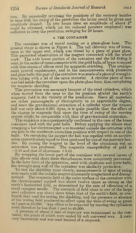
In addition to these moduli we have the QumericaJ coefficients,unity in the first term, three-eighths in the second, on, In
the third and later terms we have more than one coefficient. Table5 gives these coefficients for the first seven terms bo a Bufficienl num-ber of decimal places to secure an accuracy of l part in LOO.000 in
the value of the attraction when <z=10 cm, l\+l% 28 cm, ana c 13
cm, which correspond closely to the actual working conditions.
Table 6 .— Working coefficients
Term Coefficients
1
2
34
5
6
7
+0. 375000-. 546875
+1. 12793-2. 7493
+7.400-21.28
+0. 234375-1.02539+3. 8491-14.022+50.88
+0. 17090-1.4804+8. 6604-43.609
+0. 134.58
-1.9245+ 16.066
+0.1110-_'. 363 +0.'
The steps in the computation of the force of attraction of a finite
cylinder at any external point may now be summarized as follows:
1. From a, r 1} r2 , h, h, and c, calculate the vertical, diagonal, and
horizontal moduli.
2. Calculate the first literal term of (11).
3. Calculate the second literal term of (11).
4. By means of the moduli calculate the succeeding literal terms
(exclusive of the numerical factors).
5. Complete the calculation by applying to the literal terms the
proper numerical factors from Table 6.
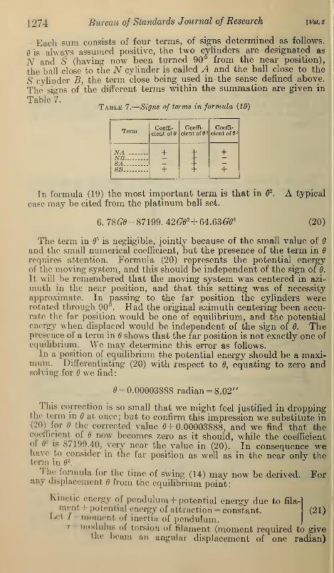
2. FORMULA FOR TIME OF SWING
We have to deal with a torsion pendulum swinging in a nonuniform
but symmetrical gravitational field, the axis of symmetry, m the
near position of the masses, coinciding with the axis oi the moving
system, and in the far position being at right angles to this axis.
Were the field uniform and parallel the formula lor the tame oi ro
would be
(13)'- 2w*\It+-2(FR)
in which / is the moment of inertia of the moving Bjretam mit+2(FR) the restoring moment per unit angular displacemen .
tM* latter exnression r is the part contributed by the modulus ..l
torsion of^themament and X(FR) the par. arudng b» the ,-,,,-
"iSft be thought that the effect of the,nonumfoimty .of the
gravitTtional1 field would disappear in the reduction of the time ol

1270 Bureau of Standards Journal of Research [Vol.5
swing to zero amplitude. As a matter of fact, such a procedure gives
a value of the constant of gravitation about 60 per cent too great.
As will shortly be shown we must substitute for R in (13) the quan-tity R(l + R/c) in the
near position, whereR/c is approximately
10/13, and in the far
position a much morecomplicated factor is
necessary. We, there-
fore, have instead of 2(FR) in (13) a quantity2(FK), where K is amore or less complicatedfunction of R, and theworking formula for the
time of swing becomes:
Vr+.2(J^K)(14)
This equation, togeth-
er with the factors Kfor the near and the far
position, may be de-rived as follows. We as-
sume the cylinder axesparallel and vertical.
Figures 7 and 8 showsections perpendicular to the axis of thecylinder. In these figures let
Figure 7.
—
Closeball plan, nearposition
B = axis of cylinder.
= center of rotation of ball.
A = neutral position of ball when0=0.
D = displaced position of ball.
c = distance between centers ofball and cylinder in neutralposition of b&W = AB.
For the near position and for the ballclose to the cylinder (fig. 7):
BD=[(OA+AB)*+OIP
- 2 (OA + AB)OD cos 0]*
= [(R + c)2 + R*-2(R + c)R cos e\'
[2.8/ B\ ~u1 + ~y ( 1 + - ) ( 1 - cos 0)
I
Figure 8.—Distant ball planv c/ J position

»rt Constant of Gravitation ] 27
1
Expanding by the binomial theorem:
BD=c[l+|(l+f)(i-ooefl
4f(1+!)Vcoea)'+ ]
DC=BD-BC=BD-c
-.[f(i+fj(i— «-J?(i gra ]
When is small2
fl4
1- COS 0=-; (l-cos0) 2 -~
Neglecting small terms involving the fourth and higher powers of 0:
i = Lift = Z>C= C[if(1 +
f)^]
Let F denote the force of attraction upon the ball at A. and Ftthat upon the ball when at D. The force F will be a function of thedistance BD between centers of cylinder and ball, though not exactlyproportional to 1/BD2
, since the cylinder is not baiycentric. Thisvariable distance BD will differ slightly from the small quantity
DC=L by the constant c; hence d{BD)=dL.Expand Fe as a function of BD by Taylor's theorem:
dF UcPFdL
+2 dUFe-F + L jt+~K TT2+
in which= F [1 + VL+V*L2 +
Tr 1 dF A T7 1 <FFV=F dL
&ndVl = 2F al?
JTT<
Since F decreases with increase of BD} j^ is negative; and since the
rate of decrease of F diminishes with increase of BD (the F curve being
concave upward)^ is positive. The usual values for these quantities
were about -0.07 for V and +0.0015 for TV We shall find it
convenient to write:
Force at D = F9= F [l-VL+V l
V+— -]
considering both V and Vx as positive. For the case of the close ball
which we are considering L is also positive.
As the ball passes from A to D its differential increase in pot
energy will be:
FedL =F [dL - VLdL + V.DdL + -...
]

1272 Bureau of Standards Journal of Research ivoi.5
For the small angle 6 and the small change in BD contemplated Vand V\ will vary but little. Integrating the last equation we obtain:
Potential energy =f[l-^VL2+ IviU~\
Applying (15):
Potential energy = ^o[|f(l +f)j^2]+
-|Fofi(i+fy (i6)
For the distant ball (fig. 8) proceeding similarly:
Expanding and neglecting small terms:
2»:-£i-f(i-|)(i~cos<>)]
DC=BD-e
2>Iift-ZX7~{lf(i-f),]
Force at D = ft =^o[1 _ yXc^Z + T^Z'dZ]
in which F and F, are considered positive and, for the distant ball, Lis oegative.
d (potential energy) = FedL =F [dL- VLdL + VxL2dL\
Potential energy =fIl-~VU+~V1u\
= -|f„B(l-fy (17)
Since (10) and (17) are identical except for sign of R, we may regardB aa positive for the close ball and negative for the distant ball, and

lleyl) Constant of Gravitation L273
with this understanding write for the potential taergy oi eynmball system in the near position:
M- 9" (is)
A typical case of the values which (18) may give may be cited fromthe platinum ball set. Denoting the two cylinders by E and U\ theball close to cylinder E by ^L and the ball close to cylinder 11 by /<',
we have:EA= +22817900*EB=-194\7G92
WA=-l9562Gd2
U7?=+23314l£02
The far position is illustrated in Figures 9 and 10, in which the
letters have the same meaning as in Figures 7 and 8. By the close ball
Figure 9.
—
Close ball plan, far
position
FIGURE 10.
—
Distant ball plan, farposition
in this case is meant that ball which is swinging from A to D to* Bid
the cylinder at B. Proceeding as in the Dear position, but keeping
terms including 6\ we find for the potential energy ot the system
including both cylinders and both balls:
Potential energy = - 2 F R( 1 - -g J J0
1274 Bureau of Standards Journal of Research [Vol. 6
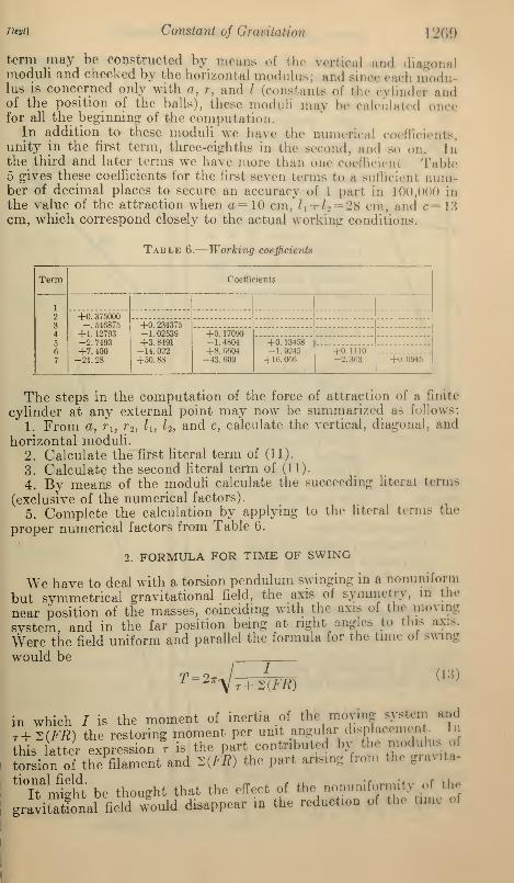
Each sum consists of four terms, of signs determined as follows.
is always assumed positive, the two cylinders are designated as
N and S (having now been turned 90° from the near position),
the ball close to the N cylinder is called A and the ball close to the
S cylinder B, the term close being used in the sense defined above.
The signs of the different terms within the summation are given in
Table?.7 , x
Table 7.
—
Signs of terms in formula (19)
Term Coeffi-
cient of 9Coeffi-
cient of 2
Coeffi-
cient of 3
NANB^
+
+
++++
+
+SASB
In formula (19) the most important term is that in 2.
case may be cited from the platinum ball set.
6. 78(75-87199. 42 Gd2 + 64. 63 Gd3
A typical
(20)
The term in 3is negligible, jointly because of the small value of
and the small numerical coefficient, but the presence of the term in
requires attention. Formula (20) represents the potential energyof the moving system, and this should be independent of the sign of 0.
It will be remembered that the moving system was centered in azi-
muth in the near position, and that this setting was of necessityapproximate. In passing to the far position the cylinders wererotated through 90°. Had the original azimuth centering been accu-rate the far position would be one of equilibrium, and the potentialenergy when displaced would be independent of the sign of 0. Thepresence of a term in shows that the far position is not exactly one ofequilibrium. We may determine this error as follows.
In a position of equilibrium the potential energy should be a maxi-mum. Differentiating (20) with respect to 0, equating to zero andsolving for we find
:
= 0.00003888 radian = 8.02"
This correction is so small that we might feel justified in droppingthe term in at once; but to confirm this impression we substitute in(20) for the corrected value 0+0.00003888, and we find that thecoefficient of now becomes zero as it should, while the coefficientof
1is 87199.40, very near the value in (20). In consequence we
have to consider in the far position as well as in the near only theterm id
2.
The formula for the time of swing (14) may now be derived.any displacement from the equilibrium point:
For
(21)
Kmctic energy of pendulum + potential energy due to fila-ment
I potential energy of attraction = constant.Let / = moment of inertia of pendulum.
t = modulus of torsion of filament (moment required to givethe beam an angular displacement of one radian)

Heyt] Constant of Gravitation\ 2flj
and (21) becomes:
i/dey i i
2\Jt) +2T d~ +
22 Craj ^-constant
Tabledfai
" P°Siti0n We find the YaIueS ° f K by IV,Vn>I,(,(l to (J9) and
Differentiating and reducing:
^+ ^Jd = (22)
an equation of the usual form for harmonic motion with a period:
In the foregoing derivation it has been assumed that the cylinderaxes are vertical. A more general calculation of a similar naturefor inclined axes shows that if the inclination of either axis is less than15' the error introduced by considering the axis vertical is less than 1
part in 100,000. The actual inclination in any experiment was muchless than this, hence the formulas for vertical axes have been usedthroughout the computations.Formula (14) applied to the near and far positions gives us two
equations for the two unknown quantities r and Qt which latter
quantity appears in F. (Seeformula (11).) Eliminating r from thesetwo equations we obtain a formula for G.
V. METHOD OF OBSERVING
1. CENTERING ADJUSTMENTS
In the foregoing discussion it is assumed that the center of rotationof the moving system is at the middle point of a straight line joiningthe axes of the cylinders. The fulfilling of this condition requuthree centering adjustments, azimuth, longitudinal and transveias indicated in Figure 11. These adjustments are best made in the
near position of the cylinders.
The azimuth adjustment was made by observing the time of Bwingat various angular settings of the cylinders. If the moving systemis centered transversely, the curve of time of swine againsl azimuthwill have a single minimum. If the transverse adjustment is suffi-
ciently off two minima will be present.
A typical azimuth centering curve is shown in Figure 12. Suchcurves were usually characterized by a rather broad and Hat mini-
mum; a well-marked double minimum was rare. The minimum

1276 Bureau of Standards Journal of Research [Vol. 5
point is best determined by means of pairs of points on the steep
slopes, and could usually be fixed to one or two tenths of a, degree.
So flat is the minimum thatquite
o CUo
o o
o oFigure 11.
—
Centering adjustments
a, Azimuth; 6, longitudinal; c; transverse.
such an accuracy is
sufficient.
Having made a first ad-justment for azimuth, thenext step was to adjusttransversely. This adjust-ment might have beenmadeby direct observation of thefilament, but it was moreconvenient to work by timeof swing. The desired pointis marked here, as in az-
imuth, by a minimum or,
in case the azimuth cen-tering is out, by a doubleminimum.The longitudinal setting
was made by observingthe filament through win-dows in the chimney. Thecurve for time of swing in
this case would be charac-terized by a maximum.Such a curve was actually
obtained as a check, but the maximum was so very flat that it wasimpossible to locate the desired point in this way within severalmillimeters.
After a first adjustment of nsdall three kinds, the azimuthand transverse settings wererepeated, sometimes twice.The longitudinal adjustment,having a very flat maximum,required little precision.
Theoretically, no furtheradj ustmentwould be requiredin the far position. The newazimuth could be set by thescale and vernier to 0.1°, aprecision equal to that obtain-able by centering. As to theother adjustments, a little
consideration will show thatthe maximum or minimum ls<*°
•
/67<>
must ho much flatter than in Figure 12.—Azimuth centering curvethe near position, and thatthese adjustments consequently require less precision in the far thanin the near position.
In practice the transverse and longitudinal adjustments were madeby moving the sliding dovetailed blocks which held up the beam B.
o

Heyl] Constant 0} Gravitation 1277
(Fig. 3 ) Such shifts of course necessitated further shift* for 00aturn ol the transverse and longitudinal adjustments after burnimr thecylinders into the far position. To provide for this the dovetailedblocks carried millimeter scales by moans of wind, it was possibleto recover the center promptly.
2. LENGTH MEASUREMENTS(a) HORIZONTAL
The horizontal measurements necessary were: (l) Distance be-tween centers of balls, and (2) distance between axes of cylindersFrom these may be calculated the distances from centers of halls
to axes of the two cylinders, the quantity c entering into the formulafor the force of attraction. In practice the second of these measure-ments was replaced by the distance between the nearest eleithe surfaces of the cylinders. This, in conjunction with the radii ofthe cylinders, gave the desired quantity.The distance between centers of balls had to be measured with
the lid of the container lifted. This measurement was thereforemade twice, before the container was closed and again, some monthslater, at the conclusion of the campaign, when the container wasreopened. In measuring this distance the microscopes of the optica]compass were sighted on the tungsten filaments by which the halls
were suspended, and at a point as far above the balls as possible(about 3 cm). Settings were made on both sides of the filament(diameter 0.025 mm) and the mean value assumed to represent thepoint of suspension, vertically above the center of gravity of the ball.
The distance between cylinders was the most troublesome andtime consuming of all the length measurements. The first thing wasto set the cylinders with their axes approximately vertical. To pre-
vent swaying of the cjdinders a small block of aluminum weighingabout 1 g was placed between container and cylinders at the bottomof the latter and fastened in place by a little wax. Similar blocks
were attached to the container at points 90° from the first blocks,
to be used in the far position of the cylinders. In changing the
position of the cylinders the blocks were left in place, and conse-
quently played no part in the computation.
The cylinders thus fixed at the bottom were adjusted by the turn-
buckles guided by a small plumb bob with a fine thread. Cal< illa-
tion showed that a variation of 15' from the vertical was allowable
with a precision of l'part in 100,000, and the actual error q as ahmuch less than this.
Direct sighting of the microscopes tangentially upon ft
of the cylinders being impracticable, the following device was found
to give satisfactory results.
In a piece of straight brass rod about 1.5 mm in diameter there
was inserted the point of a fine steel needle. (Fig. 13. rod
was let down into the space between the container and one
cylinders, and supported by a screw passing through a owof brass which, in its turn, was supported by a block of wood fast<
temporarily with wax to the lid of the container. A similar arrai
ment was provided for the other cylinder. Brass rods ..1 two differ
lengths were provided in order that the distance between the cylind
might be measured near the upper and lower ends,

1278 Bureau of Standards Journal of Research [Vol 5
In order to record and reproduce the position of the brass rod each
wooden block was provided on the top with a short piece of paper
scale across which lay the piece of metal supporting the brass rod.
It was not difficult to adjust the needle perpendicular to the line
of sight with sufficient accuracy. The magnifying power of the
microscope was such that any serious departure in this respect showeditself at once by an impairment of focus at the ends of the needle, andthe apparent change of length being a cosine function the adjustmentwas one which did not require the highest precision.
The needle was first hung a little distance from the cylinder so that
its point was visible, and a sighting mark sought on the needle somelittle distance back of the point. If there was no slight irregularity
available on theneedle one wasmade by a slight
touch of a file.
The distance fromthis sighting markto the point of theneedle (in terms of
turns of the mi-crometer) was re-
corded for eachneedle immedi-ately before use.
The needlepoints were nowplaced in contactwith the cylinders
at a determined]evel and settings
made upon thesighting marks.The distance re-
quired is evidentlythe minimum dis-
tance that can befound by setting the two needles in various positions. The followingsystematic procedure was adopted.With the needle point on the left in one fixed position the one on
the right was moved step by step along the paper scale until a mini-mum reading was obtained. It was not difficult to obtain a sym-metrical set of readings in this way. An example is given in Table 8.
Table 8.
—
Determination of minimum distance
Figure -Sighting mark for determining distancebetween cylinders
Left needle Rightneedle Distance
18.318.318.318.318.3
15.515.615.715.815.9
cm27. 852727. 848427.847627. 848527. 8530

Heyl) Constant of Gravitation L279
Such a series of measurements could usually ho repeated with anaccuracy better than 0.001 cm.Having located a minimum on one side in this way the needle was
set at this place and a minimum sou-lit with the other aeedle Lfterhaving found this, a second setting for mini.,mm was again made oneach side, resulting usually m a very small correctionAs a check of this method the diameter of one of the cylinders was
measured at several places. The moan agreed with thai obtained bythe weights and measures division of the bureau to 5 p.
(b) VERTICAL
The vertical measurements necessary were those involved in therelative positions of centers of balls and' tops of e\ linders, the inclina-tion of the aluminum rod to the horizontal and the altitude of thetriangular truss. (Fig. 4.) These measurements were made with akathetometer to a precision of about 0.1 mm. For the relative levelof balls and cylinder tops measurements wore taken through thewindows in the container at the conclusion of each determination oftime of swing. For the other two measurements, observations weremade with the lid of the container lifted.
3. TIME MEASUREMENTS
In making measurements of the time of swing the general plan usedby Braun was followed.
On the day before a series of time observations was intended theresting point of the moving system was adjusted so as to lie a.- near aspossible to the 12.5 cm mark. On the observing da}' the initial
resting point was noted and the pendulum started swinging | )V meansof the mercury bottles. Since the swings always passed oil" the Bcale,
the successive amplitudes were watched and controlled by observingthe speed with which the centimeter containing the resting pointpassed the cross wire of the telescope. The amplitudes of any twosuccessive swings are proportional to the central speeds preceding (or
following) the peak of the swing.
The multiplying factor in this case was determined by observationsmade on swings small enough to allow direct measurements of the
amplitude. The results are given in Table 9. In this table the cen-
tral speed is the speed at which the image of the scale passed the cr
wire of the observing telescope, and the amplitude is (hat of the
deflection of the image of the scale.
Table 9.
—
Relation between amplitude and central %\
Scale readingin centimeters
Restingpoint
Centralspeed
AmplitudeAmplitude
4.68
cm/min.
1.11
cm
6.32'
16.93 11.001.02 5.93 5.8
5.44 11.04.97 5. 00 5.8
16.22 11.01.92 5.21
6.15
15.51
11.01.86 4.86
.Mi .in

1280 Bureau of Standards Journal of Research [Vol. 5
It was found possible to bring up the central speed to about 9
cm/min. in about two hours by repeated changing of the positions of
the mercury bottles. This speed corresponds to an amplitude of
about 51 cm. Since the radius of the reflected ray was about 350
cm this amplitude corresponded to an angular deflection of about4°. The actual amplitudes employed in the measurements ranged
from something near this figure at starting to perhaps 1%° at the end
of a day's observing.
Having obtained the desired initial amplitude the mercury bottles
were removed, the temperature and pressure within the container
noted, and the apparatus room darkened. The observer then took
his seat at the telescope in the observing room and observed 24 suc-
cessive transits, recording on the chronograph the time of transit of
each millimeter mark from 11.0 to 14.0 cm. This required six hours
in the near position and seven in the far position, during which timethe observer remained in the same place.
By the time the observations were finished the central speed haddiminished to about one-third of its initial value. If the final speedwas slow, it was difficult to time the transits accurately; if, on the
other hand, the initial speed was too high a large reduction to zero
amplitude had to be made in the subsequent computation. Such areduction involves an extrapolation which it is desirable to keep as
small as possible. These two modes of procedure, high and low initial
speeds, were both used, the initial speeds with the glass ball set beingabout 10 per cent higher than those with the platinum balls.
The form of the amplitude-time curve for the pendulum was notstrictly that of the form y = Ae=M sin ct
tand because the pendulum
moved in a nonuniform gravitational field and because of the damp-ing factor, was not exactly isochronous. This difference amountedat most to about 1 part in 3,000. Strictly speaking, the method ofreduction employed by Braun and in the present work is not ap-plicable to a nonisochronous curve of this description, but the depart-ure from isochronism was so small and the damping factor so nearlyunity that it was found that results sufficiently accurate could beobtained in the manner about to be described.The first step was the determination of the damping factor. By
inspection of the chronograph records the middle point of a swingcould be approximately located as the point where the intervalsbetween consecutive transits were equal. At this point of the scalethe ratio of the central speeds for any two successive swings in thesame direction gave the damping factor. This proved to be about0.9, and was very nearly constant throughout any given day's run.Lne absolute value of this factor varied from day to day with varia-tions of pressure in the container, being in fact a far more sensitiveindicator of change of pressure than the manometer. The con-st. inrv of the damping factor for any given run showed that the suc-
ive amplitudes of the curve followed a geometrical progression.rhe second step was a more accurate location of the middle point
01 the swings. This can be done with considerable precision by theProcedure indicated in Table 10. In this table the column headed
i contains the difference of the numbers in columns 2.5 and 1.5.Where the Qumbers id Column II change sign is the middle point,ana irom this column lour values of the middle point are obtainable,interpolating between scale readings 12.2 and 12.3; 12.1 and 12.4;

Ileyl] Constant of Gravitation
12 and 12.5; 11.9 and 12.6. These four values sn set down belowColumn II, and their mean, L2.265, is taken as repn themiddle point durme swings 1 and 2, Similarly, swim 2 and 3 fieldthe almost identical value 12.269.Any large departure from isoohronism would brine about a «
siderable difference in the two middle points just calculated. Middlepoints later in the series, where the departure from isochronisinless, would show less and less difference.
It was customary to calculate the middle point only at the beginningand end of a run, as indicated in Table 10. It will be seen thai in
this case there has been a drift of the middle point amounting to 0. 13
cm during the day's observations. Where the drift was as small asthis it was customary to interpolate linearly between the initial andfinal values to obtain the middle points throughout the inn; but it*
there was any suspicion of irregularity or sudden change this calcula-
tion was repeated all through the series.
Table 10.
—
Calculation of middle point
Scale1.5 2.5 3.5 21.5 22.5 23.5
(2-1) (3-2) (4-3) (22-21) (23-22) (24-23)
11.9 17 25.7 17 15.7 17 26.5 17 40.0 16 59. 6 17 42. 7
12.0 24.5 17.0 25.0 35.8 17 02. 2 m. 2
.1 23.1 18.4 23.5 32.0 34.0
.2 21.8 19.8 21.9 28.4 12. 5 29.2
.3 20.3 21.4 20.4 24.4 16.7 21. s
.4 19.0 22.8 18.8 20.2 20.7 20.9
.5 17.6 24.2 17.4 16.2 2".. 16. E
.6 163 25.6 15.9 12.4 29.0 12.3
.7 14.9 27.0 14.3 08.7 32 9
.8 13.6 28.4 12.9 04.8 36.9 08. y
12.9 12.3 29.7 11.4 00.7 41.1 16 59. 1
H IIIScale
XXII XX III
(2.5-1.5) (3 .5-2.5) (22.5-21.5) (23.5-22.5)
-10.0 +10.8 11.9 -40.4 +43.1
—7.5 +8.0 12.0 -31.6 +34.0
—4.7 +5.1 .1 -23.6 +2.'.. 6
-2.0 +2.1 .2 -15.9 +18.7
+1.1 -1.0 .3 -7.7 +8.1
+3.8 -4.0 .4 +0.5 +0.2
+6.6 -6.8 .5 +8.8
+9.3 -9.7 .6 +16.6
f 12.
1
-12.7 .7 +24.2
+-14.8 —15.5 .8 +32. 1 -83.0
4-17.4 -18.3 12. y +40.4 - 12. i)
]L2.265
.266
12.268.288
.266 .270'.263 .269 . 396
.401
.408
L2.265 12.26912. 396 12. 402
Mean 12. 2712. |fl
The third step was the application of sinusoidal com* &>
curve of the fomi V =^-w sin d, to which the actual curve cloZllC 14), the period can be found by the interval b. I «

1282 Bureau of Standards Journal of Research [Vol. 5
found by the difference between the values of t for a x and a3 . In this
way values of the period may be obtained for every recorded transit
of a mark on the scale, whether at the middle point or not, and a meanvalue of considerable precision obtained.
From 24 transits we may thus obtain 22 values of the period, corre-
sponding to steadily decreasing amplitudes of the curve. Of these
periods, 11 are obtained from transits occuring on up slopes of the
curve and 11 on down slopes. Theoretically, in a sinusoid these twoslopes differ slightly in form, and, consequently, the periods derived
from the two slopes will differ slightly. For this reason the 22 periods
were reduced to 11 by taking means of consecutive pairs of up anddown values of the period.
After correction of these 11 values for damping they were reduced to
zero amplitude. For this purpose an equation was used which in-
involved the second power of the amplitude. From the 11 values of
the period normal equations were set up, and solved for the reducedtime of swing.
Figure 14.
—
Sinusoidal correction
The time of swing in the near position was usually about 1,754seconds and in the far position about 2,081 seconds, and each couldbe measured with a precision of about 0.1 second. The difference,327 seconds, formed the critical quantity of the whole measurement,and may be presumed accurate to about 1 part in 3,300. It wasgratifying to find that the average departure from the mean in eachof the two best sets of observations (with the platinum and the glassballs) proved to be of this magnitude.
VI. COMPUTATIONSNo useful purpose would be served in reproducing here the com-
putations involved m obtaining the results, as these details would*><• <»f interest only to some one planning to repeat the work. Thecomplete computations, covering about 1,000 folio sheets, and theoriginal notebooks are preserved at the library of the Bureau ofStandards. J
It may. however, be of general interest to see the relative importanceof the attraction due to the different moving parts of the apparatus.I U>le 1
1summarizes these attractions for a typical case in the near

Heyl) Constant of Gracitation 12S3
position, and Table 12 docs the same for the far portion. Tl„>figures quoted are for one of the experiment* with platinum balls.The numbers given represent the contributions of the diffeimoving parts to the quantity 2 (FK) in formula (14 >. The force duoto the balls is, of course, the preponderating factor, being aboutpercent of the whole. The next largest figure is that due to the alumi-num rod, less than 1 per cent of the total.
Table 11.—Partial values o/I {FK) in the near portion
Attraction of both cylindera on moving porta named
Parts Attraction
Balls . 419. 21502, :iu;
14010G602G
422,2060
lOtiO
Aluminum rodCopper trussCopper in barCopper hooksTungsten in moving systemMirror
Attraction of other fixed parts on balls
Supporting rods 870SO
60
50
Lower nutsTurnbucklesDisksUpper nutsTJpflm
Total 422, 3120
Table 12.
—
Partial values of Z (FK) in the far position
Attraction of both cylinders on moving parts named
Parts Attraction
Balls --- -174,3990-1.60SG-14G0
-6G-4G-40-20
109O
-600
Tungsten in moving system
Attraction of other fixed parts on balls
-440
-40
-40
Disks
-176,2290
18296°—30 7

1284 Bureau of Standards Journal of Research [Vol. 5
VII. RESULTS
1. GOLD BALLS
It has already been stated in the description of the small masses
that trouble was encountered by reason of the gold balls absorbing
mercury vapor during the seven months' period occupied by the
observations. The total increase in mass of the balls is shown in
Table 13.Table 13.—Mass of gold balls in vacuo
Date Ball A BallB
Nov 15 1924 . r ... - - -- - -- --- -- -- 48. 968849. 1067
48. 984749. 1164
.1379 .1317
The actual observations for time of swing were all grouped rather
closely together during the last half of this period. The balls wereweighed initially on November 15, 1924, and placed in position in
the apparatus, which was then closed and exhausted of air. Thecentering operations required some time and other delays ensued.As a consequence, the first actual measurement of time of swing wasmade on March 12, 1925. Seven swings were made in all, alter-
nately in the near and the far positions, the final swing occurring onJune 8, 1925. The apparatus was opened and the balls reweighedon June 15, 1925.
The average time that elapsed between swings was two weeks.If we assume the absorption of mercury to have proceeded regularlyduring the whole seven months, the increase in two weeks would beabout 0.01 g. for each ball, or about one-twentieth of 1 per cent.If we assume also that the mercury penetrated the gold balls withspherical symmetry (which from the final appearance of the ballsseems reasonable) we may interpolate for the mass of the balls atany period of observation without introducing an error of more thanperhaps 1 part in 10,000.
Calculation shows that an error of this magnitude in the mass ofthe balls will give rise to an error of about 4 parts in 10,000 in thevalue of G. It was, therefore, thought worth while to compute theresults for the gold ball set on the basis of the assumptions thathave been mentioned. The results are shown in Table 14.
Table 14.—Constant of gravitation derived from experiments with gold balls
6.683X10-86. 681X10-86.676X10-86.678X10-86.679X10-86.672X10⁻⁸
Mean - 6.678X10⁻⁸
Average departure from mean.. . .003
2. PLATINUM BALLSTo avoid the difficulty of mercury absorption a second set of
measurementB was made with platinum balls coated thinly with

Ileal] Constant of Gravitation! 285
lacquer. The balls were weighed initially on October 10 1926 and
and hook; the final weight included such portion of the tungstenfilament as was wrapped around the hook, together with hewax that held it in place. The final weigh was used in the ,,putations. The results obtained are shown in Table 15.
Table 15.
—
Masses in vacuo of platinum balk
Date
Oct, 10, 1925.Nov. 7, 1926.
Hull A Hull 11
Five values of the constant of gravitation were obtained from thisset-up, shown in Table 16.
Table 16.—Constant of gravitation derived from experiments with platinum balls
Mean...
Average departure from mean.
6.661XKH<;.ct;ixio- s
6. 667X10-*6.667X10-*0.064X10⁻⁸
. 6.004X10⁻⁸
. .002
3. GLASS BALLS
A third set of experiments was made with balls of optical glass, ofdensity 3.6. These balls, like those of metal, had am.
|
proxi-
mately 50 g, and, consequently, a diameter of about 3 cm. Tne ballswere made with a finely ground finish and were truly spherical to0.001 cm.The masses of the balls are given in Table 17.
Table 17.
—
Masses of glass balls in vacuo
Ban a Ball B
The glass removed in making the hole was in each case about
The final weight, with hook, adhering filament, and wax, was used
in the computations.Five results were obtained with the glass halls, shown in Table I
s".
Table 18.—Constant of gravitation derived from experiment* villi glass balls
ID --
Average departure from mean
- < 10-*
;'10-»

1286 Bureau of Standards Journal of Research [Vol. 5
It is interesting to compare these mean results and their measures
of precision. This is done in Table 19.
Table 19.
—
Comparison of results
MaterialExtremevalues
Meanvalue
Averagedeparturefrom mean
Gold - --f 6. 683
I 6. 672
/ 6. 667
\ 6. 661
/ 6. 678
\ 6. 671
} 6. 678
} 6. 664
} 6. 674
0.003
.002
.002
4. MEAN VALUE
It will be seen that the spread of the gold ball results is abouttwice as great as those with either platinum or glass, and that there
is an overlapping of the spreads with gold and glass. It is evidentthat the gold ball results are much less reliable than either of theother sets.
The results with platinum and glass may be rated as of equalexcellence, the average departure being the same and the spreadssmall and approximately equal. Discarding the gold results andgiving equal weights to platinum and glass we obtain
6.669 X10"8
with an average departure from the mean of 0.005. It seems advis-able to us, however, to retain the gold results at one-third the weightof either platinum or glass. This gives as a final result
6.670 X10"8
with an average departure from the mean of 0.005.
5. DISCUSSION OF RESULTS
The first thing that attracts attention in the results given in Table19 is the apparent difference with the nature of the material. Themean values of the platinum and glass sets, for instance, differ byan amount five times as great as the average departure of either set.Moreover, there is no overlap in their spreads.
Bowever, an explanation of this variation on the basis of differenceoj material is not admissible. As already stated (footnote (1))Knlvos, by his very ingenious torsion balance method, has demon-strated the constancy of the gravitation constant for a number ofmat (Minis (including platinum) to a precision of 6 parts in 109
. Hedid not however test optical glass. While there is no doubt thattne result obtained by Eotvos is universally valid, it seemed best torepeat his torsion balance experiment with the balls of platinum andglass. his work was carried out by Dr. G. S. Cook, of the Bureau01 standards, and is described in Section VIII. The high precisiono the negative results obtained rules out any attempt to explain then mat inn () | ITSU i ts on a basis of difference of material. Some otherexplanation is necessary.

He^ Constant of Gravitation [287
To account for the observed differences it is necefactor which vanes in the several aeries of experiments and do(eliminate in the near and far positions. Perhaps the first explanationthat suggests itself is that of incomplete magnetic sMeldine Theevidence on this point (III, 6) appears conclush e, but is st renei henedby the following considerations.Gold is diamagnetic and platinum paramagnetic. Anj
magnetic effect would, therefore, weaken the attraction on the goldballs and strengthen it on platinum; but the values of actuallyobtained are less for platinum than for gold.
It was recognized that the gravitational field in the room was Dotuniform, due partly to the upright stand carrying the pump attach-ments, and partly to the walls of the room*. Two of these werebacked with earth and two were merely partitions.Such a field, however, being stationary, should produce no effect
that would not be ehminated in the near and far positions.It was recognized also that the resting position of the moving
system was slightly different with respect to the field of the room inthe several series of experiments, but it is not apparent that thiswould produce any effect that would not be eliminated.
Probably the solution of this difficulty can best be attained byworking with an apparatus sufficiently sensitive to give the next,
decimal place. Should the variation found fail to appear in its
present place, but be shifted farther on, the difficulty, while notexplained, would obviously be ascribable to some experimental error.
Such an apparatus has been constructed, in which the difference
of the two times of swing is about 100 minutes. This apparatusawaits the construction of the next new building at the Bureau of
Standards, when opportunity may offer to provide a basement roomlarge enough to contain it comfortably.
VIII. THE SPECIFIC ATTRACTION OF PLATINUM ANDGLASS 8
The experimental values of the constant of gravitation as given in
the preceding section vary for small masses of different materials by
an amount greater than the averag edeparture of the single values for
any particular material. It seems reasonable to attribute this to
experimental error of some nature, but it is possible to interpret it as
a departure from Newton's law of the proportionality of mass and
weight.The Cavendish apparatus is not suited for the detection ol
small departures from this law, since the forces involved are so small,
but it is possible to test this point in other ways to a very nigfl degree
of precision. Such experiments have invariably shown, to the degr< e
of precision of which the apparatus was capable that the ratio ol
mass to weight is independent of the material Pendulum expen-
ments conducted by Newton • established tin, to I part m 1,000,
and similar experiments by Bessel10 of a more refined clia r.-h, cax-
^This section and the experimental work it describes are due to Dr. G. S. Cook, of the Hureau of Stand.
» Principia, Book III, Prop. 6, Theorem 6.
10 Pogg. Annalen, 25, p. 401; 1832.

1288 Bureau of Standards Journal of Research [Voi.s
ried the precision to one part in 60,000. It is worthy of note that
Bessel included among the substances tested by him meteoric iron andmeteoric stone.
The most precise experiments are those of Eotvos, 11 who by an
ingenious application of the torsion balance succeeded in pushing the
precision to 6 parts in 109. The substances examined by him were
water, copper, platinum, magnalium, copper sulphate (solid andsolution), asbestos and talc. As he did not test glass, it was thought
worth while to repeat the Eotvos experiment with one of the glass
balls actually employed in the determination of the constant of gravita-
tion balanced against a ball of platinum.
In the Eotvos experiment two masses of different materials are
suspended from the ends of the beam of a torsion balance. Thesemasses may be thought of as acted upon by the gravitational attrac-
tion of the earth (a force which may not be proportional to the massesof the two bodies), and by a centrifugal force due to the rotation of
the earth, which will be proportional to the masses. If then the
gravitational force is not proportional to the masses the resultant
forces on the two bodies will be in different directions, and in conse-
quence a torque must be supplied by the suspending filament in orderto hold the beam in equilibrium in an east and west position. Thistorque must be reversed if the beam (together with the torsion head)is turned through 180°.
In practice, the whole apparatus, including observing telescopeand scale, was rotated. In this way the effect sought would showitself as a change in the equilibrium position.
H. A. Wilson 12 has given the theory of this experiment in a some-what simpler form than that employed by Eotvos. The apparatusused in the present work was in dimensions and arrangement similarto that described by Wilson.The torsion balance consisted of a light aluminum beam about 5
cm long carrying a glass ball at one end and a platinum ball at theother. The beam was supported at its center by a tungsten filament0.025 mm in diameter and about 43 cm long. The beam was inclosedin a case of cast iron with walls 1 cm thick to avoid magnetic dis-turbances, and the case was exhausted of air to a pressure of about 2mm of mercury.To the case was attached a reading telescope and scale such as are
used with wall galvanometers. The whole apparatus was placed ona level plate and pivoted so that it might be readily turned about itsvortical axis. Deflections were read through a window in the caseby means of the telescope and scale. Table 20 shows the readingsobtained.
u Annalen der Physik, 68, 1, pp. 11-G6; 1922. U Phys. Rev., 20, pp. 75-77; July, 1922.

H*fl Constant of GravitationI 281
»
Table 20.—Resting points in centimeters observed with BdM
Platinum ball east Platinum ball
1. 10
1.38
L-88
1.32
1.27
1. 26
1.24
Mean. 1.819
1. in
L17
1.34
i.:;i
L26
1. 335
Difference, 0.006 cm clock w Ise
Scale distance from mirror on beam,
The formula given by Wilson is as follows:
9 £-« 2<ft*
T2si i
(23)
in whichg = acceleration of gravitation.
2A = change in azimuth angle when beam is turned 180°.
2d = distance between centers of balls suspended from beam.t = period of the earth's rotation.
= latitude of place of the experiment.
T= period of vibration of the torsion balance.
r = radious of earth.
At Washington = 38° 54', and the following values were observed :
Taking # = 980, we get;
T=315 sec.
2d = 4.9 cm
^—/- = 2AX6Xl(r 4
In the experiment, 2A = 6X 10⁻³ consequently
9-9'= 3.6X10-
(24)
While this result, from its minuteness, is of do importance m the
present instance, it may be stated for the sake oi completj
the difference, regarded as real, is in the direction whi
correspond to the different values of ^obtained for glass
Its only value in the present work is to prove tl
apparently found with glass and platinum is not to D<
a basis of difference of material.
The value of 2A obtained from Table 20 is just about
able limit, being read from a scale of niillimeters. Ichange

1290 Bureau of Standards Journal of Research [Vol s
in resting point shown in Table 20 is the typical behavior of a sus-
pension immediately after a load has been placed upon it. It is
quite marked here because of the fact that several hours always
elapsed between successive readings. This lapse of time was neces-
sary because of the small damping.
IX. SUMMARY AND GENERAL CONCLUSIONS
The value adopted for the constant of gravitation as a result of
experiments with small masses of gold, platinum, and glass, weighted,
respectively, as 1, 3, and 3, is, in c. g.^s. units
1 o™ -26,670 X10~8 cm3 g" 1
sec.
with a precision, as measured by the average departure from themean, of 0.005.
This result agrees well with that obtained by Boys and Braun,namely 6.66 ±0.01.The different results obtained with the various materials used for
the small masses are yet to be explained, but evidence is given thatthis difference is not to be ascribed to the nature of the material.
Washington, April 10, 1930.