Embed Size (px)
Citation preview

Journal of Information Processing Vol.24 No.3 470–482 (May 2016)
[DOI: 10.2197/ipsjjip.24.470]
Regular Paper
A Real-time Audio-to-audio Karaoke Generation Systemfor Monaural Recordings Based on Singing Voice
Suppression and Key Conversion Techniques
Hideyuki Tachibana1,†1,a) YuMizuno1,†2 Nobutaka Ono2,b) Shigeki Sagayama3,c)
Received: July 31, 2015, Accepted: February 8, 2016
Abstract: This paper describes an automatic karaoke generation system, which can suppress the singing voice in au-dio music signals, and can also change the pitch of the song. Furthermore, this system accepts the streaming input, andit works in real-time. To the best of our knowledge, there have been no real-time audio-to-audio karaoke system thathas the two functions above. This paper particularly describes the two technical components, as well as some com-ments on the implementation. In this system, the authors employed two signal processing techniques: singing voicesuppression that is based on two-stage HPSS, a vocal enhancement technique that the authors proposed previously, anda pitch shift technique that is based on the spectrogram stretch and phase vocoder. The attached video file shows thatthe system works in real-time, and the sound quality may be practically acceptable.
Keywords: karaoke, music signal processing, singing voice, music application
1. Introduction
Karaoke is said to be invented in 1971 [56], and it is regardedas one of the earliest examples of electric-technology-based mu-sic applications for amateur music fans. It is currently one ofthe major ways of enjoying music, and is considered as one ofmajor leisure activities. For example, karaoke was the 7th mostpopulous leisure in Japan in 2011, in terms of the number of par-ticipants (38.4 million) [21]. (Note: the population of Japan wasabout 128 million in 2010.) This digit is comparable to those ofother major leisure activities including watching movies, playingvideo games, and listening to music.
On the other hand, the songs created by amateur musicians,which are typically distributed through web sites, have becomeconsiderably popular recently, especially in the last decade. Re-cent growth of the web-based music community prompts manyamateur musicians to upload their songs, and many listeners en-joy these songs as well as the songs created by professional mu-sicians. (Relevant discussion on the web-based community ofamateur musicians is found in Refs. [14], [15], etc.) However, itis not necessarily economic to create the karaoke data for all thesongs of these kinds, remembering that the current karaoke sys-tems require pre-made MIDI data, which are created manually byskilled craftspeople who have the ability of music dictation.
1 The University of Tokyo2 National Institute of Informatics, Chiyoda, Tokyo 101–8430, Japan3 School of Interdisciplinary Mathematical Sciences, Meiji University,
Nakano, Tokyo 164–8525, Japan†1 Presently with PKSHA Technology Inc.†2 Presently with Aichi Prefectural Governmenta) [email protected]) [email protected]) [email protected]
Thus the techniques that can generate karaoke signals automat-ically from mixed music signals, such as MP3 data, has signifi-cance. In order to create karaoke data from mixed music signals,we can consider principally two approaches as follows,(a) Audio→MIDI→MIDI→ Audio A possible approach
may be the sequential processing as follows.( 1 ) Audio to MIDI conversion, which may be based on gen-
eral music transcription techniques such as multiple F0
analysis (e.g., Ref. [22]).( 2 ) Estimate which parts of the MIDI data are melody, and
delete them from the MIDI data.( 3 ) MIDI → Audio synthesis, which is a traditional tech-
nology of computer music.However, this approach is not easy for now, because thereare still many difficulties to solve the subproblems (1) and(2).
(b) Audio→ Audio Another approach may be the direct audio-to-audio conversion, using some signal processing tech-niques. See also Section 1.1.1. This paper considers thisapproach.
On the basis of the motivations above, the authors developedan interactive music player named “Euterpe,” which generatesquasi-karaoke signals from ordinary music signals. The systemdoes not require separately-recorded tracks of a song, but it onlyrequires the already-mixed music audio signals (such as ordinaryCDs, MP3 data, etc.) The system enables users to reduce thevocal part and change the key of accompanying sounds. Further-more, the system works in real-time. Moreover, we specificallyassume that the input signal is monaural because of the reasonsdescribed in Section 1.1.1. To the best of our knowledge, therehave been no real-time automatic karaoke systems that integratedthese two important features above: singing voice suppression
c© 2016 Information Processing Society of Japan 470
Journal of Information Processing Vol.24 No.3 470–482 (May 2016)
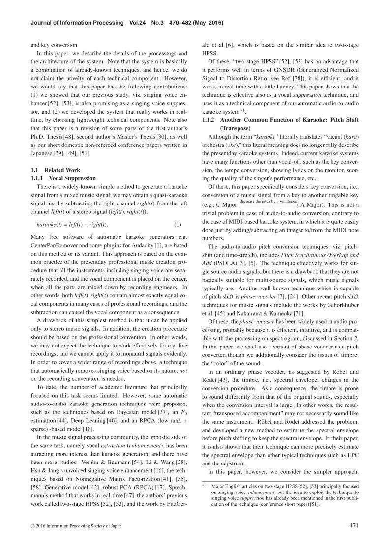
and key conversion.In this paper, we describe the details of the processings and
the architecture of the system. Note that the system is basicallya combination of already-known techniques, and hence, we donot claim the novelty of each technical component. However,we would say that this paper has the following contributions:(1) we showed that our previous study, viz. singing voice en-hancer [52], [53], is also promising as a singing voice suppres-sor, and (2) we developed the system that really works in real-time, by choosing lightweight technical components. Note alsothat this paper is a revision of some parts of the first author’sPh.D. Thesis [48], second author’s Master’s Thesis [30], as wellas our short domestic non-refereed conference papers written inJapanese [29], [49], [51].
1.1 Related Work1.1.1 Vocal Suppression
There is a widely-known simple method to generate a karaokesignal from a mixed music signal; we may obtain a quasi-karaokesignal just by subtracting the right channel right(t) from the leftchannel left(t) of a stereo signal (left(t), right(t)),
karaoke(t) = left(t) − right(t). (1)
Many free software of automatic karaoke generators e.g.CenterPanRemover and some plugins for Audacity [1], are basedon this method or its variant. This approach is based on the com-mon practice of the presentday professional music creation pro-cedure that all the instruments including singing voice are sepa-rately recorded, and the vocal component is placed on the center,when all the parts are mixed down by recording engineers. Inother words, both left(t), right(t) contain almost exactly equal vo-cal components in many cases of professional recordings, and thesubtraction can cancel the vocal component as a consequence.
A drawback of this simplest method is that it can be appliedonly to stereo music signals. In addition, the creation procedureshould be based on the professional convention. In other words,we may not expect the technique to work effectively for e.g. liverecordings, and we cannot apply it to monaural signals evidently.In order to cover a wider range of recordings above, a techniquethat automatically removes singing voice based on its nature, not
on the recording convention, is needed.To date, the number of academic literature that principally
focused on this task seems limited. However, some automaticaudio-to-audio karaoke generation techniques were proposed,such as the techniques based on Bayesian model [37], an F0
estimation [44], Deep Leaning [46], and an RPCA (low-rank +sparse) -based model [18].
In the music signal processing community, the opposite side ofthe same task, namely vocal extraction (enhancement), has beenattracting more interest than karaoke generation, and there havebeen more studies: Vembu & Baumann [54], Li & Wang [28],Hsu & Jang’s unvoiced singing voice enhancement [16], the tech-niques based on Nonnegative Matrix Factorization [41], [55],[58], Generative model [42], robust PCA (RPCA) [17], Sprech-mann’s method that works in real-time [47], the authors’ previouswork called two-stage HPSS [52], [53], and the work by FitzGer-
ald et al. [6], which is based on the similar idea to two-stageHPSS.
Of these, “two-stage HPSS” [52], [53] has an advantage thatit performs well in terms of GNSDR (Generalized NormalizedSignal to Distortion Ratio; see Ref. [38]), it is efficient, and itworks in real-time with a little latency. This paper shows that thetechnique is effective also as a vocal suppression technique, anduses it as a technical component of our automatic audio-to-audiokaraoke system *1.1.1.2 Another Common Function of Karaoke: Pitch Shift
(Transpose)Although the term “karaoke” literally translates “vacant (kara)
orchestra (oke),” this literal meaning does no longer fully describethe presentday karaoke systems. Indeed, current karaoke systemshave many functions other than vocal-off, such as the key conver-sion, the tempo conversion, showing lyrics on the monitor, scor-ing the quality of the singer’s performance, etc.
Of these, this paper specifically considers key conversion, i.e.,conversion of a music signal from a key to another singable key
(e.g., C Majordecrease the pitch by 3 semitones−−−−−−−−−−−−−−−−−−−−−−−→ A Major). This is not a
trivial problem in case of audio-to-audio conversion, contrary tothe case of MIDI-based karaoke system, in which it is quite easilydone just by adding/subtracting an integer to/from the MIDI notenumbers.
The audio-to-audio pitch conversion techniques, viz. pitch-shift (and time-stretch), includes Pitch Synchronous OverLap and
Add (PSOLA) [3], [5]. The technique effectively works for sin-gle source audio signals, but there is a drawback that they are notbasically suitable for multi-source signals, which music signalstypically are. Another well-known technique which is capableof pitch shift is phase vocoder [7], [24]. Other recent pitch shifttechniques for music signals include the works by Schorkhuberet al. [45] and Nakamura & Kameoka [31].
Of these, the phase vocoder has been widely used in audio pro-cessing, probably because it is efficient, intuitive, and is compat-ible with the processing on spectrogram, discussed in Section 2.In this paper, we shall use a variant of phase vocoder as a pitchconverter, though we additionally consider the issues of timbre;the “color” of the sound.
In an ordinary phase vocoder, as suggested by Robel andRodet [43], the timbre, i.e., spectral envelope, changes in theconversion procedure. As a consequence, the timbre is proneto sound differently from that of the original sounds, especiallywhen the conversion interval is large. In other words, the resul-tant “transposed accompaniment” may not necessarily sound likethe same instrument. Robel and Rodet addressed the problem,and developed a new method to estimate the spectral envelopebefore pitch shifting to keep the spectral envelope. In their paper,it is also shown that their technique can more precisely estimatethe spectral envelope than other typical techniques such as LPCand the cepstrum,
In this paper, however, we consider the simpler approach,
*1 Major English articles on two-stage HPSS [52], [53] principally focusedon singing voice enhancement, but the idea to exploit the technique tosinging voice suppression has already been mentioned in the first publi-cation of the technique (conference short paper) [51].
c© 2016 Information Processing Society of Japan 471

Journal of Information Processing Vol.24 No.3 470–482 (May 2016)
namely LPC-based spectral envelope extraction, since we alsoplace emphasis on efficiency in this paper, as discussed in Sec-tion 3.
Thus our technique is based on the following two techniques.This configuration has also been considered in our previous con-ference paper [29].(1) Spectrogram Stretch Expand/shrink the given power spec-
trogram in the direction of frequency axis, keeping the spec-tral envelope fixed.
(2) Waveform Synthesis from Amplitude Spectrogram:Obtain the waveform from the modified amplitude spectro-gram using RTISI-LA [59], a variant of phase vocoder.
1.1.3 Interactive Music PlayersThe concept of audio-to-audio conversion of a music signal
is relevant to some of the interactive music applications basedon music signal processing [23]. The proposal system mayalso be related to the concept “Active Music Listening” [12],which enables users to enjoy music interactively and actively,instead of just listening to it. Many systems, related to theconcept, have been developed recently, including Drumix [57],MusicKIOSK [10], etc.
1.2 Paper OrganizationThe rest of this paper is organized as follows. Section 2 de-
scribes the fundamentals of signal processing techniques on spec-trogram. Busy readers may skip this section but Section 2.2.2may be useful to understand Section 5. Section 3 describes therequirements of the karaoke systems that we discuss in this pa-per. In Section 4 and Section 5, we describe the signal processingtechniques which we utilized in the system. In Section 6, wediscuss some issues on implementation. Finally Section 7 con-cludes the paper.
2. Signal Processing on Spectrogram
Before discussing the specific techniques of singing voice sup-pression and pitch shift, let us briefly recall the fundamentals ofmusic signal processing.
2.1 Short-time Fourier Transform and Spectrogram2.1.1 Complex Spectrogram
In music signal processing, it is common to formulate tech-niques on the time-frequency plane, which is called ‘spectro-
gram.’ (See e.g., Ref. [23].) Given a discrete signal x(t) ∈R
fsampTtotal , by applying the Short-time Fourier Transform (STFT)to it, a complex spectrogram. X = (Xn,k)1≤n≤N,1≤k≤K ∈ CN×K ,is obtained, where STFT : R fsampTtotal → C
N×K is defined byXn,k = STFTL [x(t)] = FFTL [x(nS − L/2 + t)w(t)], where FFT :R
L → CK is the Fast Fourier Transform, which maps a signalu(t) to a spectrum u(k). The definitions of the other symbols areshown in Table 1.2.1.2 Amplitude Spectrogram
The absolute value of a complex spectrogram, X = (Xn,k)n,k =
(|Xn,k |) ∈ R≥0N×K , is called an amplitude spectrogram. Figure 1
shows an example of the amplitude spectrogram of a music sig-nal.
Many audio signal processing techniques are indeed a conver-
Table 1 List of the symbols used in the definition of STFT.
Symbol MeaningL ∈ 2N (even number) frame lengthS ∈ N frame hop size (frame shift)fsamp [Hz] sampling rateTtotal [s] length of the songN := � fsampTtotal/S � number of time framesK := L/2 + 1 number of frequency binsn ∈ Z, 1 ≤ n ≤ N time indexk ∈ Z, 1 ≤ k ≤ K frequency indexw(t) window function
Fig. 1 An example of the amplitude spectrogram. The music signal is ex-cerpted from RWC database [11]. Blue bins are silent, while green,yellow, and red are louder. Higher frequencies are enhanced for vis-ibility. (This figure is extracted from the author’s previous publica-tion [50].)
sion from an amplitude spectrogram X ∈ R≥0N×K into another
Y ∈ R≥0N×K . That is, Y ← f (X ) where f is some processing on
the spectrogram. A famous “ f ” is time-frequency masking, whichis not used in this paper, but is sometimes regarded as commonsense in audio signal processing literature.
2.2 Inverse STFT (Wave Synthesis from a Spectrogram)2.2.1 Complex Spectrogram→Waveform
After the processing on the spectrogram, we need to transformthe spectrogram back to the waveform.
A transform from a complex spectrogram to a waveform israther trivial; we can synthesize the waveform x(t) ∈ R fsampT byapplying an inverse STFT technique to the complex spectrogramX ∈ CN×K .
A simple inverse STFT technique is based on a tandem connec-tion of the inverse FFT and a simple wave concatenation which iscalled overlap-add. For the details of the inverse STFT algorithm,see e.g., Ref. [23].2.2.2 Amplitude Spectrogram→Waveform
Contrary to the case of complex spectrogram, the transforma-tion from an amplitude spectrogram to a waveform is an ill-posedproblem. Since we do not have any information on the phaseψn,k ∈ [0, 2π) where Yn,k = Yn,ke
√−1ψn,k , we need to estimate thephase spectrogram (ψn,k) to apply the inverse STFT mentioned.
There are typically two methods to obtain a phase spectrogramas follows.(a) Diversion of the Original Store the phase spectrogram
(φn,k) of the input complex spectrogram X , whereXn,k = |Xn,k |e
√−1φn,k . Then, we use it in inverse STFTassuming that ψn,k ≈ φn,k. That is, let ψn,k = φn,k, and applythe inverse STFT, y(t) = STFT−1
L [Yn,ke√−1ψn,k ].
c© 2016 Information Processing Society of Japan 472
Journal of Information Processing Vol.24 No.3 470–482 (May 2016)
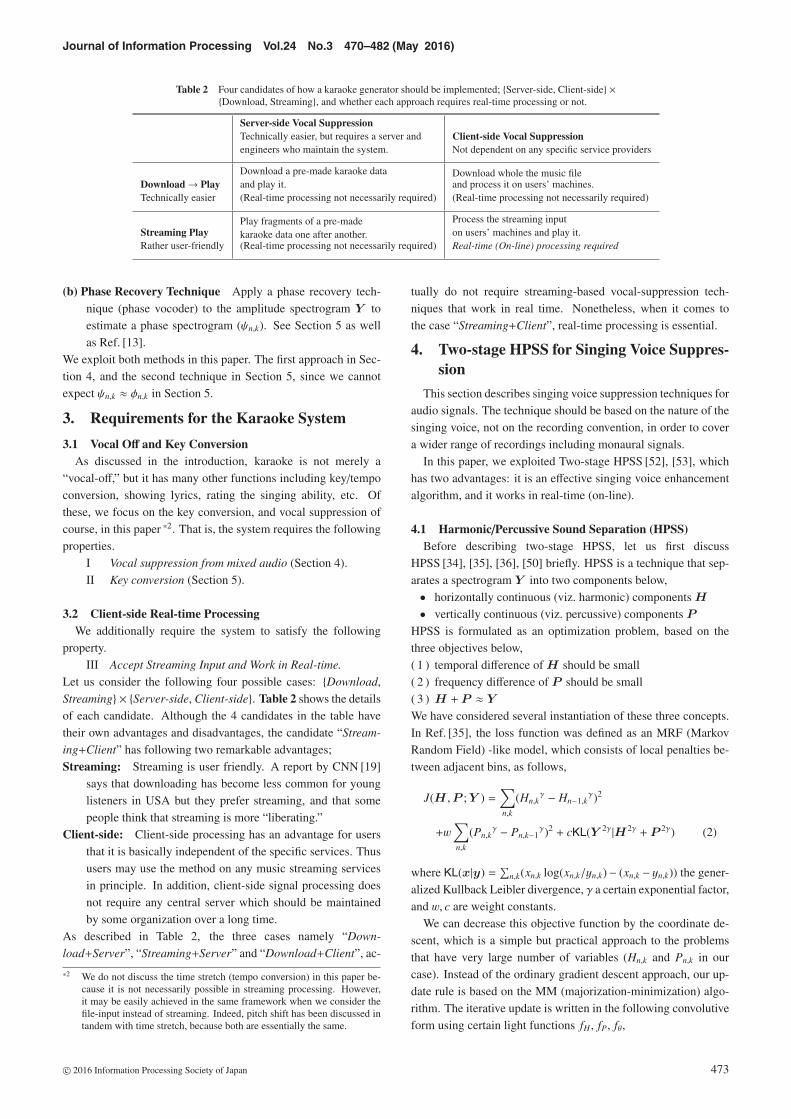
Table 2 Four candidates of how a karaoke generator should be implemented; {Server-side, Client-side} ×{Download, Streaming}, and whether each approach requires real-time processing or not.
Server-side Vocal SuppressionTechnically easier, but requires a server andengineers who maintain the system.
Client-side Vocal SuppressionNot dependent on any specific service providers
Download→ PlayTechnically easier
Download a pre-made karaoke dataand play it.(Real-time processing not necessarily required)
Download whole the music fileand process it on users’ machines.(Real-time processing not necessarily required)
Streaming PlayRather user-friendly
Play fragments of a pre-madekaraoke data one after another.(Real-time processing not necessarily required)
Process the streaming inputon users’ machines and play it.Real-time (On-line) processing required
(b) Phase Recovery Technique Apply a phase recovery tech-nique (phase vocoder) to the amplitude spectrogram Y toestimate a phase spectrogram (ψn,k). See Section 5 as wellas Ref. [13].
We exploit both methods in this paper. The first approach in Sec-tion 4, and the second technique in Section 5, since we cannotexpect ψn,k ≈ φn,k in Section 5.
3. Requirements for the Karaoke System
3.1 Vocal Off and Key ConversionAs discussed in the introduction, karaoke is not merely a
“vocal-off,” but it has many other functions including key/tempoconversion, showing lyrics, rating the singing ability, etc. Ofthese, we focus on the key conversion, and vocal suppression ofcourse, in this paper *2. That is, the system requires the followingproperties.
I Vocal suppression from mixed audio (Section 4).II Key conversion (Section 5).
3.2 Client-side Real-time ProcessingWe additionally require the system to satisfy the following
property.III Accept Streaming Input and Work in Real-time.
Let us consider the following four possible cases: {Download,Streaming} × {Server-side, Client-side}. Table 2 shows the detailsof each candidate. Although the 4 candidates in the table havetheir own advantages and disadvantages, the candidate “Stream-
ing+Client” has following two remarkable advantages;Streaming: Streaming is user friendly. A report by CNN [19]
says that downloading has become less common for younglisteners in USA but they prefer streaming, and that somepeople think that streaming is more “liberating.”
Client-side: Client-side processing has an advantage for usersthat it is basically independent of the specific services. Thususers may use the method on any music streaming servicesin principle. In addition, client-side signal processing doesnot require any central server which should be maintainedby some organization over a long time.
As described in Table 2, the three cases namely “Down-
load+Server”, “Streaming+Server” and “Download+Client”, ac-
*2 We do not discuss the time stretch (tempo conversion) in this paper be-cause it is not necessarily possible in streaming processing. However,it may be easily achieved in the same framework when we consider thefile-input instead of streaming. Indeed, pitch shift has been discussed intandem with time stretch, because both are essentially the same.
tually do not require streaming-based vocal-suppression tech-niques that work in real time. Nonetheless, when it comes tothe case “Streaming+Client”, real-time processing is essential.
4. Two-stage HPSS for Singing Voice Suppres-sion
This section describes singing voice suppression techniques foraudio signals. The technique should be based on the nature of thesinging voice, not on the recording convention, in order to covera wider range of recordings including monaural signals.
In this paper, we exploited Two-stage HPSS [52], [53], whichhas two advantages: it is an effective singing voice enhancementalgorithm, and it works in real-time (on-line).
4.1 Harmonic/Percussive Sound Separation (HPSS)Before describing two-stage HPSS, let us first discuss
HPSS [34], [35], [36], [50] briefly. HPSS is a technique that sep-arates a spectrogram Y into two components below,• horizontally continuous (viz. harmonic) components H
• vertically continuous (viz. percussive) components P
HPSS is formulated as an optimization problem, based on thethree objectives below,( 1 ) temporal difference of H should be small( 2 ) frequency difference of P should be small( 3 ) H + P ≈ Y
We have considered several instantiation of these three concepts.In Ref. [35], the loss function was defined as an MRF (MarkovRandom Field) -like model, which consists of local penalties be-tween adjacent bins, as follows,
J(H ,P ; Y ) =∑n,k
(Hn,kγ − Hn−1,k
γ)2
+w∑n,k
(Pn,kγ − Pn,k−1
γ)2 + cKL(Y 2γ |H2γ + P 2γ) (2)
where KL(x|y) =∑
n,k(xn,k log(xn,k/yn,k)− (xn,k − yn,k)) the gener-alized Kullback Leibler divergence, γ a certain exponential factor,and w, c are weight constants.
We can decrease this objective function by the coordinate de-scent, which is a simple but practical approach to the problemsthat have very large number of variables (Hn,k and Pn,k in ourcase). Instead of the ordinary gradient descent approach, our up-date rule is based on the MM (majorization-minimization) algo-rithm. The iterative update is written in the following convolutiveform using certain light functions fH , fP, fθ,
c© 2016 Information Processing Society of Japan 473
Journal of Information Processing Vol.24 No.3 470–482 (May 2016)
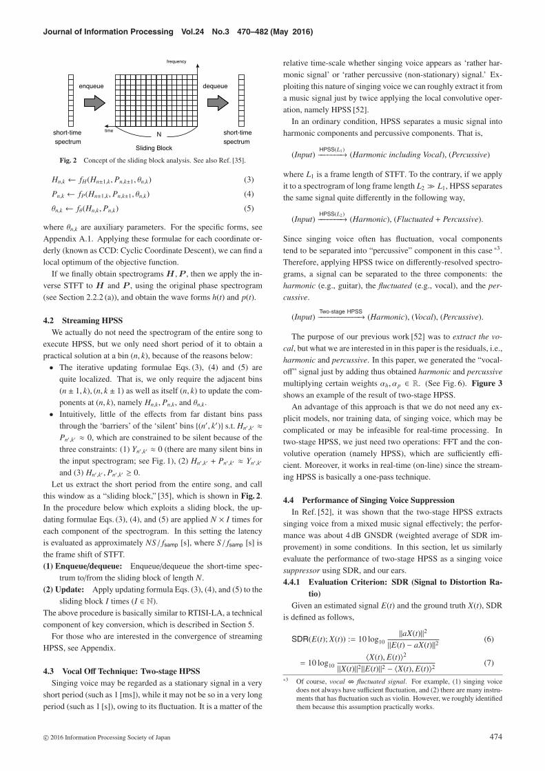
Fig. 2 Concept of the sliding block analysis. See also Ref. [35].
Hn,k ← fH(Hn±1,k, Pn,k±1, θn,k) (3)
Pn,k ← fP(Hn±1,k, Pn,k±1, θn,k) (4)
θn,k ← fθ(Hn,k, Pn,k) (5)
where θn,k are auxiliary parameters. For the specific forms, seeAppendix A.1. Applying these formulae for each coordinate or-derly (known as CCD: Cyclic Coordinate Descent), we can find alocal optimum of the objective function.
If we finally obtain spectrograms H ,P , then we apply the in-verse STFT to H and P , using the original phase spectrogram(see Section 2.2.2 (a)), and obtain the wave forms h(t) and p(t).
4.2 Streaming HPSSWe actually do not need the spectrogram of the entire song to
execute HPSS, but we only need short period of it to obtain apractical solution at a bin (n, k), because of the reasons below:• The iterative updating formulae Eqs. (3), (4) and (5) are
quite localized. That is, we only require the adjacent bins(n ± 1, k), (n, k ± 1) as well as itself (n, k) to update the com-ponents at (n, k), namely Hn,k, Pn,k, and θn,k.
• Intuitively, little of the effects from far distant bins passthrough the ‘barriers’ of the ‘silent’ bins {(n′, k′)} s.t. Hn′ ,k′ ≈Pn′ ,k′ ≈ 0, which are constrained to be silent because of thethree constraints: (1) Yn′ ,k′ ≈ 0 (there are many silent bins inthe input spectrogram; see Fig. 1), (2) Hn′ ,k′ + Pn′ ,k′ ≈ Yn′ ,k′
and (3) Hn′ ,k′ , Pn′ ,k′ ≥ 0.Let us extract the short period from the entire song, and call
this window as a “sliding block,” [35], which is shown in Fig. 2.In the procedure below which exploits a sliding block, the up-dating formulae Eqs. (3), (4), and (5) are applied N × I times foreach component of the spectrogram. In this setting the latencyis evaluated as approximately NS/ fsamp [s], where S/ fsamp [s] isthe frame shift of STFT.(1) Enqueue/dequeue: Enqueue/dequeue the short-time spec-
trum to/from the sliding block of length N.(2) Update: Apply updating formula Eqs. (3), (4), and (5) to the
sliding block I times (I ∈ N).The above procedure is basically similar to RTISI-LA, a technicalcomponent of key conversion, which is described in Section 5.
For those who are interested in the convergence of streamingHPSS, see Appendix.
4.3 Vocal Off Technique: Two-stage HPSSSinging voice may be regarded as a stationary signal in a very
short period (such as 1 [ms]), while it may not be so in a very longperiod (such as 1 [s]), owing to its fluctuation. It is a matter of the
relative time-scale whether singing voice appears as ‘rather har-monic signal’ or ‘rather percussive (non-stationary) signal.’ Ex-ploiting this nature of singing voice we can roughly extract it froma music signal just by twice applying the local convolutive oper-ation, namely HPSS [52].
In an ordinary condition, HPSS separates a music signal intoharmonic components and percussive components. That is,
(Input)HPSS(L1)−−−−−−−→ (Harmonic including Vocal), (Percussive)
where L1 is a frame length of STFT. To the contrary, if we applyit to a spectrogram of long frame length L2 L1, HPSS separatesthe same signal quite differently in the following way,
(Input)HPSS(L2)−−−−−−−→ (Harmonic), (Fluctuated + Percussive).
Since singing voice often has fluctuation, vocal componentstend to be separated into “percussive” component in this case *3.Therefore, applying HPSS twice on differently-resolved spectro-grams, a signal can be separated to the three components: theharmonic (e.g., guitar), the fluctuated (e.g., vocal), and the per-
cussive.
(Input)Two-stage HPSS−−−−−−−−−−−−→ (Harmonic), (Vocal), (Percussive).
The purpose of our previous work [52] was to extract the vo-
cal, but what we are interested in in this paper is the residuals, i.e.,harmonic and percussive. In this paper, we generated the “vocal-off” signal just by adding thus obtained harmonic and percussive
multiplying certain weights αh, αp ∈ R. (See Fig. 6). Figure 3shows an example of the result of two-stage HPSS.
An advantage of this approach is that we do not need any ex-plicit models, nor training data, of singing voice, which may becomplicated or may be infeasible for real-time processing. Intwo-stage HPSS, we just need two operations: FFT and the con-volutive operation (namely HPSS), which are sufficiently effi-cient. Moreover, it works in real-time (on-line) since the stream-ing HPSS is basically a one-pass technique.
4.4 Performance of Singing Voice SuppressionIn Ref. [52], it was shown that the two-stage HPSS extracts
singing voice from a mixed music signal effectively; the perfor-mance was about 4 dB GNSDR (weighted average of SDR im-provement) in some conditions. In this section, let us similarlyevaluate the performance of two-stage HPSS as a singing voicesuppressor using SDR, and our ears.4.4.1 Evaluation Criterion: SDR (Signal to Distortion Ra-
tio)Given an estimated signal E(t) and the ground truth X(t), SDR
is defined as follows,
SDR(E(t); X(t)) := 10 log10‖aX(t)‖2
‖E(t) − aX(t)‖2 (6)
= 10 log10〈X(t), E(t)〉2
‖X(t)‖2‖E(t)‖2 − 〈X(t), E(t)〉2 (7)
*3 Of course, vocal � fluctuated signal. For example, (1) singing voicedoes not always have sufficient fluctuation, and (2) there are many instru-ments that has fluctuation such as violin. However, we roughly identifiedthem because this assumption practically works.
c© 2016 Information Processing Society of Japan 474

Journal of Information Processing Vol.24 No.3 470–482 (May 2016)
Fig. 4 (a) Histogram of SDR(A; A) of the 5000 music clips (1,000 clips × 5 input SNRs). Each dotindicates a music clip. The averaged value for each input SNR is 7.4 dB (−10 dB input SNR),5.5 dB (−5 dB), 2.5 dB (0 dB), −1.4 dB (5 dB) and −5.9 dB (10 dB), respectively. (b) Histogramof SDR(A; V), similarly. Blue lines indicate the baseline (the levels of the input signals), andthe black boxes indicate the mean ± sd. The averaged value for each input SNR is −14.2 dB(−10 dB),−10.4 dB (-5 dB), −6.6 dB (0 dB), −3.1 dB (5 dB) and −0.4 dB (10 dB), respectively. Ani,Kenshin, . . . are the IDs of the singers.
Fig. 3 An example of the result of two-stage HPSS. Top figure shows thespectrogram of a mixed music signal. Middle figure shows the spec-trogram of extracted singing voice by two-stage HPSS. Bottom fig-ure shows the spectrogram of the residual component, i.e., the sumof the ‘harmonic’ and ‘percussive,’ which is roughly equal to the ac-companiment.
where 〈·, ·〉 denotes the inner product, ‖x‖2 := 〈x, x〉, and a ∈ Ris a certain constant that satisfies 〈X(t), E(t) − aX(t)〉 = 0. Intu-itively, SDR(E(t); X(t)) indicates the strength of the target signalX(t) in the estimated E(t). Evidently, “SDR = r dB” means that
Table 3 Parameters of the two-stage HPSS.
Parameter ValueSampling Rate fsamp 16,000 [Hz]
Short Frame
Frame length L1 256 (=16 [ms])Frame hop size S 1 128 (=8 [ms])Parameter w 1Parameter c 0.2Parameter γ 1Sliding block size N 30
Long Frame
Frame length L2 4,096 (=256 [ms])Frame hop size S 2 2,048 (=128 [ms])Parameter w 1Parameter c 0.2Parameter γ 1Sliding block size N 30
the target signal X(t) is 10r/10 times louder than the distortionE(t) − aX(t).
Let V(t), A(t) be the ground truth vocal and accompaniment,and V(t), A(t) are the estimated, respectively. What we want toevaluate here is SDR(A(t); A(t)), i.e., the strength of the groundtruth in the obtained “accompaniment.” *4
4.4.2 Experiment & ResultLet us evaluate SDRs using real music signals. The parameters
we used in this experiment are shown in Table 3. We evaluatedthe SDR of the accompaniment using the MIR-1K dataset, similarto Ref. [52].
*4 Since singing voice enhancement and suppression are “two sides of thesame coin,” the result, i.e. SDR(A(t); A(t)) may be basically similar tothe value of SDR(V(t); V(t)) in Ref. [52]. Indeed, it is easily verified
SDR(A(t); A(t)) = SDR(V(t); V(t)) − input SNR
where input SNR is SDR(V + A; V), if we can assume 〈V(t), A(t)〉 =〈V(t), ε(t)〉 = 〈A(t), ε(t)〉 = 0, and V(t) = V(t) + ε(t), A(t) = A(t) − ε(t)where ε(t) is the distortion. Nevertheless, it is not necessarily the case.
c© 2016 Information Processing Society of Japan 475
Journal of Information Processing Vol.24 No.3 470–482 (May 2016)
Figure 4 (a) shows the distribution of SDR(A(t); A(t))), i.e.,the strength of the accompaniment in the output signal. The his-togram is plotted by the singers. The values of SDR were higherthan the levels of the input signals on average if input SNR is 0,5, and 10 dB. This suggests that the accompaniment A(t) becamerelatively louder in the output A(t), compared with the input sig-nal Input(t) = A(t) + V(t), in these conditions. This figure showsthat the trend does not strongly depend on the individual singer.On the other hand, if input SNR is −5 and −10 dB (i.e., the casesthat the accompaniment is louder than the vocal), the output qual-ity was lower than the baseline on average. This is possibly be-cause the deterioration of the accompaniment has more impacton the digits than the vocal reduction does in the low input SNRcase.
Figure 4 (b) shows the distribution of SDR(A(t); V(t))), i.e., thestrength of the singing voice in the output signal. This shows thatthe singing voice tends to reside quite little in the output signalson average. It is seen also in this figure that the trend does notstrongly depend on the individual singer.4.4.3 Comparison to Other Methods
The digits, however, are not as good as the state-of-the-art tech-niques e.g., Ref. [18], according to the digits reported in the Fig-ure in the literature [18]. Figure 5 in Ref. [18] shows that theperformance (GNSDR) of RPCA [17] is about 1.5 dB, and thatthat of Ikemiya’s method (RPCA-F0) is about 6 dB. The corre-sponding GNSDR value of our method is about 2.5 dB (averagedSDR(A; A) when input SNR = 0 dB). These digits indicate thatthe performance of our method is a little better than RPCA, whilemuch worse than RPCA-F0. Nevertheless, our method has theadvantage that it is suitable for real-time processing.
4.5 Audio ExamplesIn the attached video file, the examples of the output are shown.
Listen to the attached Audio 1a, 1b (RWC-MDB-P-2001 No.7),2a, 2b (No.13), 3a, 3b (No.98). The songs 1a, 2a, 3a were ex-cerpted from RWC database [11], and converted to mono 16 kHz.The clips 1b, 2b, 3b are the result.
Listening to these examples, we can find that the output sig-nals contain less vocal components than the input signals, as theexperiment above suggests. Although the output signals containsome distortions, they may be largely acceptable as karaoke sig-nals.
5. Key Conversion with Fixed Spectral Enve-lope
As discussed in Section 1 and Section 2, karaoke is not merelya vocal-off, but it has much more functions including key conver-sion. This section describes a simple technique to convert the key
(e.g., “C Major,” “D Major,” etc) of a music signal.
5.1 Key Conversion Based on Resampling and PhaseVocoder
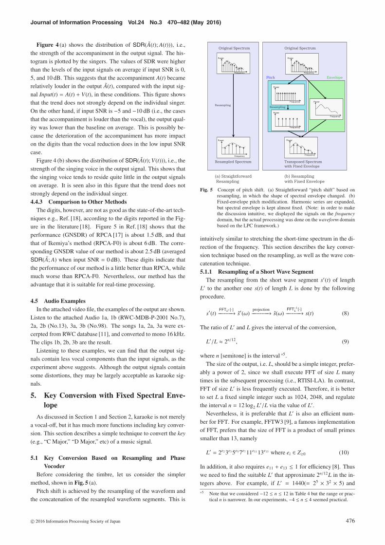
Before considering the timbre, let us consider the simplermethod, shown in Fig. 5 (a).
Pitch shift is achieved by the resampling of the waveform andthe concatenation of the resampled waveform segments. This is
Fig. 5 Concept of pitch shift. (a) Straightforward “pitch shift” based onresampling, in which the shape of spectral envelope changed. (b)Fixed-envelope pitch modification. Harmonic series are expanded,but spectral envelope is kept almost fixed. (Note: in order to makethe discussion intuitive, we displayed the signals on the frequencydomain, but the actual processing was done on the waveform domainbased on the LPC framework.)
intuitively similar to stretching the short-time spectrum in the di-rection of the frequency. This section describes the key conver-sion technique based on the resampling, as well as the wave con-catenation technique.5.1.1 Resampling of a Short Wave Segment
The resampling from the short wave segment s′(t) of lengthL′ to the another one s(t) of length L is done by the followingprocedure.
s′(t)FFTL′ [·]−−−−−−→ s′(ω)
projection−−−−−−−→ s(ω)FFT−1
L [·]−−−−−−→ s(t) (8)
The ratio of L′ and L gives the interval of the conversion,
L′/L ≈ 2n/12, (9)
where n [semitone] is the interval *5.The size of the output, i.e. L, should be a simple integer, prefer-
ably a power of 2, since we shall execute FFT of size L manytimes in the subsequent processing (i.e., RTISI-LA). In contrast,FFT of size L′ is less frequently executed. Therefore, it is betterto set L a fixed simple integer such as 1024, 2048, and regulatethe interval n = 12 log2 L′/L via the value of L′.
Nevertheless, it is preferable that L′ is also an efficient num-ber for FFT. For example, FFTW3 [9], a famous implementationof FFT, prefers that the size of FFT is a product of small primessmaller than 13, namely
L′ = 2e2 3e3 5e5 7e7 11e11 13e13 where ei ∈ Z≥0 (10)
In addition, it also requires e11 + e13 ≤ 1 for efficiency [8]. Thuswe need to find the suitable L′ that approximate 2n/12L in the in-tegers above. For example, if L′ = 1440(= 25 × 32 × 5) and
*5 Note that we considered −12 ≤ n ≤ 12 in Table 4 but the range or prac-tical n is narrower. In our experiments, −4 � n � 4 seemed practical.
c© 2016 Information Processing Society of Japan 476
Journal of Information Processing Vol.24 No.3 470–482 (May 2016)
L = 1024, the ratio L′/L = 45/32 ≈ 25.902/12 approximates 26/12
finely. (Cf. �1024 × 26/12� = 1448 = 23 × 181, and 181 is prime.)Table 4 shows such approximate values we have found.5.1.2 Phase Vocoder (Concatenation of Inconsistent Wave
Segments)On the basis of the above procedure, we convert the input wave
segment
s′n(t), cn − L′/2 ≤ t < cn + L′/2 (11)
to the output wave segment, whose key is (12 log2 L′/L) semi-tones higher,
sn(t), cn − L/2 ≤ t < cn + L/2 (12)
where cn is the center of each frame, i.e., cn = nS where S is theframe shift of STFT.
The wave segments obtained above, however, have a problemthat the neighboring wave segments sn(t) and sn+1(t) are inconsis-tent. Then, in order to connect these wave segments, we need toemploy a technique to reconstruct the waveform from a modifiedamplitude spectrogram, as discussed in Section 2.2.2.
We then used the phase vocoder here, which is efficient andintuitive. A basic method is the one proposed by Griffin &Lim [13], which is a simple iteration of the STFT and inverseSTFT. Some variant of the technique are known such as the workby Le Roux et al. [25], [26], [27], Perruadin et al. [39], but in thispaper, we used a method proposed by Zhu et al. [59], which iscalled Real-Time Iterative Spectrum Inversion with Look Ahead
(RTISI-LA). As the name suggests, the method works in real time.RTISI-LA is based on the similar architecture to the streamingHPSS discussed above, i.e., it is basically the iteration of theSTFT and inverse STFT on the “sliding block.”
5.2 Spectrogram Modification with Fixed Spectral EnvelopeA drawback of the method discussed in the previous subsec-
tion is that the timbre, i.e. spectral envelope, of the spectrum alsochanges, as claimed in Ref. [29], [43]. In order to avoid this prob-lem, we first decomposes a spectrum into the envelope and thepitch by LPC analysis [20], [40] to obtain the two data. Then thesystem applies the pitch shifting technique based on the resam-pling described above, while the spectral envelope is kept fixed,as described in Fig. 5 (b).
Table 4 Approximate values of 2n/12 which makes L′ = 2n/12L a simpleinteger written as a product of small primes when L is power of 2e.g., 1024, 2048.
positive n negative n
2 1/12 ≈ 135/128 2 −1/12 ≈ 15/162 2/12 ≈ 9/8 2 −2/12 ≈ 225/2562 3/12 ≈ 1215/1024 2 −3/12 ≈ 27/322 4/12 ≈ 5/4 2 −4/12 ≈ 405/5122 5/12 ≈ 675/512 2 −5/12 ≈ 3/42 6/12 ≈ 45/32 2 −6/12 ≈ 45/642 7/12 ≈ 3/2 2 −7/12 ≈ 675/10242 8/12 ≈ 405/256 2 −8/12 ≈ 5/82 9/12 ≈ 27/16 2 −9/12 ≈ 75/128210/12 ≈ 225/128 2−10/12 ≈ 9/16211/12 ≈ 15/8 2−11/12 ≈ 135/256
6. Does the System Really Work in Real-time?— Implementation of the System
6.1 Overview of the ImplementationIn this section we describe the implementation of the sys-
tem. The source code of the system is available on the author’sGitHub *6. Note we implemented the system to receive the inputfrom the audio input jack, instead of the streaming input via theweb, but they are essentially similar. Almost all of the system iscoded in C++ except the GUI which is written in Tcl/Tk.
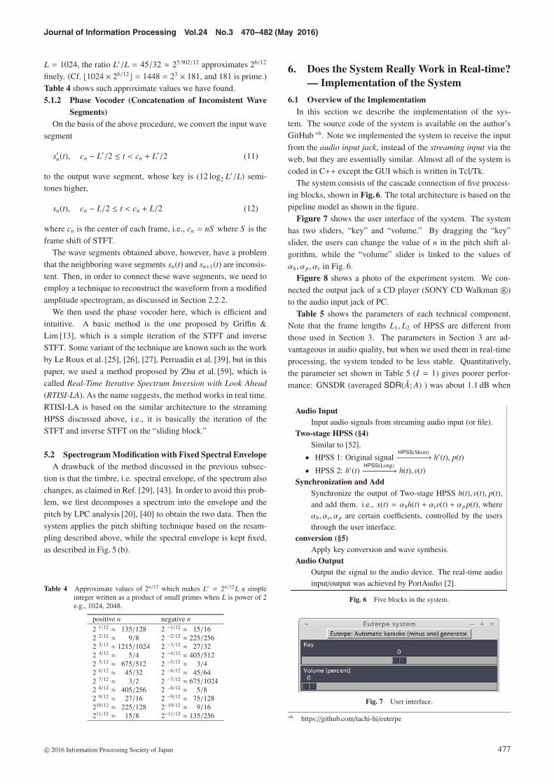
The system consists of the cascade connection of five process-ing blocks, shown in Fig. 6. The total architecture is based on thepipeline model as shown in the figure.
Figure 7 shows the user interface of the system. The systemhas two sliders, “key” and “volume.” By dragging the “key”slider, the users can change the value of n in the pitch shift al-gorithm, while the “volume” slider is linked to the values ofαh, αp, αv in Fig. 6.
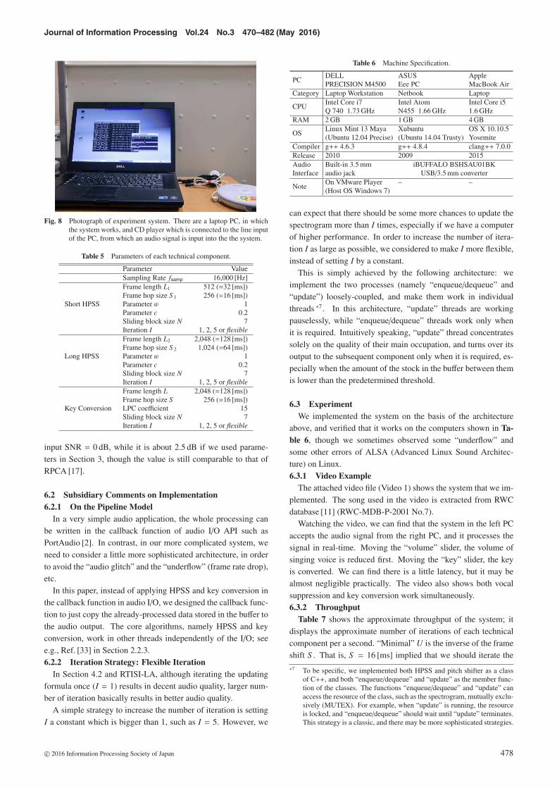
Figure 8 shows a photo of the experiment system. We con-nected the output jack of a CD player (SONY CD Walkman R©)to the audio input jack of PC.
Table 5 shows the parameters of each technical component.Note that the frame lengths L1, L2 of HPSS are different fromthose used in Section 3. The parameters in Section 3 are ad-vantageous in audio quality, but when we used them in real-timeprocessing, the system tended to be less stable. Quantitatively,the parameter set shown in Table 5 (I = 1) gives poorer perfor-mance: GNSDR (averaged SDR(A; A) ) was about 1.1 dB when
Fig. 6 Five blocks in the system.
Fig. 7 User interface.
*6 https://github.com/tachi-hi/euterpe
c© 2016 Information Processing Society of Japan 477
Journal of Information Processing Vol.24 No.3 470–482 (May 2016)
Fig. 8 Photograph of experiment system. There are a laptop PC, in whichthe system works, and CD player which is connected to the line inputof the PC, from which an audio signal is input into the the system.
Table 5 Parameters of each technical component.
Parameter ValueSampling Rate fsamp 16,000 [Hz]
Short HPSS
Frame length L1 512 (=32 [ms])Frame hop size S 1 256 (=16 [ms])Parameter w 1Parameter c 0.2Sliding block size N 7Iteration I 1, 2, 5 or flexible
Long HPSS
Frame length L2 2,048 (=128 [ms])Frame hop size S 2 1,024 (=64 [ms])Parameter w 1Parameter c 0.2Sliding block size N 7Iteration I 1, 2, 5 or flexible
Key Conversion
Frame length L 2,048 (=128 [ms])Frame hop size S 256 (=16 [ms])LPC coefficient 15Sliding block size N 7Iteration I 1, 2, 5 or flexible
input SNR = 0 dB, while it is about 2.5 dB if we used parame-ters in Section 3, though the value is still comparable to that ofRPCA [17].
6.2 Subsidiary Comments on Implementation6.2.1 On the Pipeline Model
In a very simple audio application, the whole processing canbe written in the callback function of audio I/O API such asPortAudio [2]. In contrast, in our more complicated system, weneed to consider a little more sophisticated architecture, in orderto avoid the “audio glitch” and the “underflow” (frame rate drop),etc.
In this paper, instead of applying HPSS and key conversion inthe callback function in audio I/O, we designed the callback func-tion to just copy the already-processed data stored in the buffer tothe audio output. The core algorithms, namely HPSS and keyconversion, work in other threads independently of the I/O; seee.g., Ref. [33] in Section 2.2.3.6.2.2 Iteration Strategy: Flexible Iteration
In Section 4.2 and RTISI-LA, although iterating the updatingformula once (I = 1) results in decent audio quality, larger num-ber of iteration basically results in better audio quality.
A simple strategy to increase the number of iteration is settingI a constant which is bigger than 1, such as I = 5. However, we
Table 6 Machine Specification.
PCDELL ASUS ApplePRECISION M4500 Eee PC MacBook Air
Category Laptop Workstation Netbook Laptop
CPUIntel Core i7 Intel Atom Intel Core i5Q 740 1.73 GHz N455 1.66 GHz 1.6 GHz
RAM 2 GB 1 GB 4 GB
OSLinux Mint 13 Maya Xubuntu OS X 10.10.5(Ubuntu 12.04 Precise) (Ubuntu 14.04 Trusty) Yosemite
Compiler g++ 4.6.3 g++ 4.8.4 clang++ 7.0.0Release 2010 2009 2015Audio Built-in 3.5 mm iBUFFALO BSHSAU01BKInterface audio jack USB/3.5 mm converter
NoteOn VMware Player – –(Host OS Windows 7)
can expect that there should be some more chances to update thespectrogram more than I times, especially if we have a computerof higher performance. In order to increase the number of itera-tion I as large as possible, we considered to make I more flexible,instead of setting I by a constant.
This is simply achieved by the following architecture: weimplement the two processes (namely “enqueue/dequeue” and“update”) loosely-coupled, and make them work in individualthreads *7. In this architecture, “update” threads are workingpauselessly, while “enqueue/dequeue” threads work only whenit is required. Intuitively speaking, “update” thread concentratessolely on the quality of their main occupation, and turns over itsoutput to the subsequent component only when it is required, es-pecially when the amount of the stock in the buffer between themis lower than the predetermined threshold.
6.3 ExperimentWe implemented the system on the basis of the architecture
above, and verified that it works on the computers shown in Ta-ble 6, though we sometimes observed some “underflow” andsome other errors of ALSA (Advanced Linux Sound Architec-ture) on Linux.6.3.1 Video Example
The attached video file (Video 1) shows the system that we im-plemented. The song used in the video is extracted from RWCdatabase [11] (RWC-MDB-P-2001 No.7).
Watching the video, we can find that the system in the left PCaccepts the audio signal from the right PC, and it processes thesignal in real-time. Moving the “volume” slider, the volume ofsinging voice is reduced first. Moving the “key” slider, the keyis converted. We can find there is a little latency, but it may bealmost negligible practically. The video also shows both vocalsuppression and key conversion work simultaneously.6.3.2 Throughput
Table 7 shows the approximate throughput of the system; itdisplays the approximate number of iterations of each technicalcomponent per a second. “Minimal” U is the inverse of the frameshift S . That is, S = 16 [ms] implied that we should iterate the
*7 To be specific, we implemented both HPSS and pitch shifter as a classof C++, and both “enqueue/dequeue” and “update” as the member func-tion of the classes. The functions “enqueue/dequeue” and “update” canaccess the resource of the class, such as the spectrogram, mutually exclu-sively (MUTEX). For example, when “update” is running, the resourceis locked, and “enqueue/dequeue” should wait until “update” terminates.This strategy is a classic, and there may be more sophisticated strategies.
c© 2016 Information Processing Society of Japan 478

Journal of Information Processing Vol.24 No.3 470–482 (May 2016)
Table 7 Throughput of each technical component. (top): U [Times/s] be-ing the number of updates per a second. The values are empiricallyevaluated. (middle): Number of iterations I, being the value ofthe designed value if the iteration strategy is “Fixed,” or the valueevaluated by I ≡ U/S −1 if the iteration strategy is “Flex.” (bottom):“Flex.” and “Fixed” are the iteration strategy of the component.
Short HPSS Long HPSSkey conv.
Note(RTISI-LA)
DELLU ≈4000 U ≈1000 U ≈1000I ≈64 I ≈64 I ≈16Flex. Flex. Flex.
DELLU ≈312 U ≈78 U ≈1400I = 5 I = 5 I ≈22 Video exampleFixed Fixed Flex.
ASUSN/A N/A N/A
Not stable enoughI = 1 I = 1 N/AFixed Fixed Flex.
ASUSU ≈124 U ≈31 U ≈124I = 2 I = 2 I = 2Fixed Fixed Fixed
MacBook AirU ≈ 32000 U ≈ 7700 U ≈ 3800I ≈ 512 I ≈ 493 I ≈ 61Flex. Flex. Flex.
Minimal Requirements
U[Times/s] U ≥ 62.5 U ≥ 15.6 U ≥ 62.5 rhs= S −1
I[Times] I ≥ 1 I ≥ 1 I ≥ 1S [ms] 16 [ms] 64 [ms] 16 [ms]
updating formulae at least 62.5 times per second. This is the min-imal number of iterations which is required to apply the updatingformulae to all the bins at least once, keeping up with the real-time.
The table shows that powerful machines, namely the worksta-tion (DELL 2010) and MacBook Air (2015), can execute the up-dating formulae of HPSS and RTISI-LA luxuriously many times,much more than practically required (see Appendix). The ta-ble also shows that even an old netbook (ASUS 2009) can catchup with the real-time, executing the updating formulae twice asmany times as the minimal requirement, though it is not stableenough if we employ the flexible iteration strategy.
7. Concluding Remarks
7.1 Summary and ConclusionWe developed an automatic karaoke generating system
“Euterpe,” which aimed at generating a karaoke signal au-tomatically from a wider range of music signals, especiallymonaural music signals, to which we cannot apply the sim-ple center-removal-based “karaoke generator,” contrary to theprofessionally-created stereo signals.
This system has two functions: singing voice suppression andkey conversion.• The singing voice suppression is based on two-stage HPSS,
which is effective as a vocal enhancer in our previous study.Simple evaluation and sample audio files showed that thetechnique also works effectively as a vocal suppressor.
• The key conversion is based on the pitch shift techniquebased on phase vocoder, but has a little improvement fromG&L algorithm: it works in real-time because it is based onRTISI-LA, and it keeps the timbre of the sound because ofthe LPC analysis.
We also described the architecture of the implementation of the
whole systems, which is based on the pipeline model. Because ofthe architecture, we achieved a real-time karaoke generating sys-tem, which is especially important when we consider a client-sidestreaming-based karaoke generating system. The attached videofile may be showing that the latency and the sound quality is ac-ceptable for now.
7.2 Future WorkThere is still room for improvement of the sound quality such
as the following.• The obtained “accompaniment” has ambiguous articulation.
This problem basically comes from the long HPSS, whichis, however, the most important component of vocal suppres-sion.
• The volume of the sound is uneven through the song. Es-pecially the “harmonic” components are occasionally quiteloud.
• The sound quality is rather poor especially when the intervalof key conversion is large, such as n � −5, 5 � n.
These issues should be addressed in the future, but we should notethat too complicated techniques may impair the real-time nature.
Another possible future work will be the development of a sys-tem which is more faithful to ordinary karaoke systems. Addingsome other functions such as showing lyrics is a challnege for thefuture.
Another future work will be the development of more intelli-gent karaoke systems, such as one that follows the user’s singing,similar to some of the automatic accompaniment systems [4], [32]that follow the MIDI piano. This may be a dreamy technical chal-lenge in the future.
Acknowledgments Part of this work was supported byGrant-In-Aid for JSPS Research Fellows (22-6961) and Kak-enhi Grant-In-Aid for Scientific Research (A). In the processof the development of the real-time system we were supportedby Mr. Takuho Nakano (program test) and Dr. Takuya Nishimoto(advice on real-time audio I/O).
References
[1] Audacity Vocal Removal Plug-ins, available from〈http://wiki.audacityteam.org/wiki/Vocal Removal Plug-ins〉 (ac-cessed 2016-02).
[2] Bencina, R. and Burk, P.: PortAudio – An Open Source Cross Plat-form Audio API, Proc. 2001 International Computer Music Confer-ence (ICMC), pp.263–266 (2001).
[3] Charpentier, F.J. and Stella, M.G.: Diphones Synthesis using anOverlap-add Technique for Speech Waveforms Concatenation, Proc.ICASSP, pp.2015–2018 (1986).
[4] Dannenberg, R.: An On-line Algorithm for Real-time Accompani-ment, Proc. ICMC, pp.193–198 (1984).
[5] Moulines, E. and Charpentier, F.: Pitch-synchronous Waveform Pro-cessing Techniques for Text-to-speech Synthesis using Diphones,Speech Communication, Vol.9, No.5-6, pp.453–467 (1990).
[6] FitzGerald, D. and Gainza, M.: Single Channel Vocal Separation us-ing Median Filtering and Factorisation Techniques, ISAST Trans. Elec-tronic and Signal Processing, Vol.4, No.1, pp.62–73 (2010).
[7] Flanagan, J.L. and Golden, R.M.: Phase Vocoder, Bell System Techni-cal Journal, Vol.45, pp.1493–1509 (1966).
[8] Frigo, M. and Johanson, S.G.: FFTW users manual, available from〈http://www.fftw.org/doc/〉, 〈http://www.fftw.org/fftw3.pdf〉.
[9] Frigo, M. and Johanson, S.G.: The design and implementation ofFFTW3, Proc. IEEE, Vol.93, No.2, pp.216–231 (2005).
[10] Goto, M.: SmartMusicKIOSK: Music Listening Station with Chorus-Search Function, Proc. 16th Annual ACM Symposium on User Inter-
c© 2016 Information Processing Society of Japan 479

Journal of Information Processing Vol.24 No.3 470–482 (May 2016)
face Software and Technology, Vol.5, pp.31–40 (2003).[11] Goto, M.: Development of the RWC Music Database, Proc. 18th In-
ternational Congress on Acoustics (ICA 2004), pp.I–553–556 (2004).[12] Goto, M.: Active Music Listening Interfaces Based on Signal Process-
ing, Proc. 2007 IEEE International Conferences on Acoustics, Speech,and Signal Processing, pp.1441–1444 (2007).
[13] Griffin, D.W. and Lim, J.S.: Signal Estimation From Modified Short-Time Fourier Transform, IEEE Trans. Audio, Speech, and Signal Pro-cessing, Vol.32, No.2, pp.236–243 (1984).
[14] Hamasaki, M., Takeda, H., Hope, T. and Nishimura, T.: NetworkAnalysis of an Emergent massively Collaborative Creation Commu-nity – How Can People Create Videos Collaboratively without Collab-oration?, Proc. 3rd International ICWSM Conference, AAAI, pp.222–225 (2009).
[15] Hamasaki, M., Takeda, H. and Nishimura, T.: Network Analysisof Massively Collaborative Creation of Multimedia Contents – CaseStudy of Hatsune Miku Videos on Nico Nico Douga, Proc. 1st Inter-national Conference on Designing Interactive User Experiences forTV and Video (UXTV), pp.165–168, ACM (2008).
[16] Hsu, C.-L. and Jang, J.-S.R.: on The Improvement of Singing VoiceSeparation for Monaural Recordings using The MIR-1K Dataset,IEEE Trans. Audio, Speech, and Language Processing (2010).
[17] Huang, P.-S., Chen, S.D., Smaragdis, P. and H.-Johnson, M.: Singing-voice separation from monaural recordings using robust principalcomponent analysis, Proc. 2012 IEEE International Conference onAudio, Speech, and Signal Processing (ICASSP 2012), pp.57–60(2012).
[18] Ikemiya, Y., Yoshii, K. and Itoyama, K.: Singing Voice Analysis andEditing based on Mutually Dependent F0 Estimation and Source Sep-aration, Proc. ICASSP (2015).
[19] Imam, J.: Young Listeners Opting to Stream, Not Own Music (2012),available from 〈http://edition.cnn.com/2012/06/15/tech/web/music-streaming/index.html〉.
[20] Itakura, F. and Saito, S.: Digital Filtering Techniques for SpeechAnalysis and Synthesis, Proc. International Conference on Indepen-dent Component Analysis and Blind Signal Separation, Vol.25-C-1,pp.261–264 (1971).
[21] Japan Productivity Center: White Paper of Leisure 2011 (2011) (inJapanese).
[22] Klapuri, A.: Multiple Fundamental Frequency Estimation based onHarmonicity and Spectral Smoothness, IEEE Trans. Speech AudioProcess., Vol.11, No.6, pp.804–816 (2003).
[23] Klapuri, K. and Davy, M.: Signal Processing Methods for Music Tran-scription, Springer (2006).
[24] Laroche, J. and Dolson, M.: Improved Phase Vocoder Time-ScaleModification of Audio, IEEE Trans. Speech and Audio Processing,Vol.7, No.3, pp.323–332 (1999).
[25] Le Roux, J.: Exploiting Regularities in Natural Acoustical Scenes forMonaural Audio Signal Estimation, Decomposition, Restoration andModification, Ph.D. Thesis, The University of Tokyo (2009).
[26] Le Roux, J., Ono, N. and Sagayama, S.: Explicit Consistency Con-straints for STFT Spectrograms and Their Application to Phase Re-construction, Proc. Workshops on Statistical and Perceptual Audition(SAPA) (2008).
[27] Le Roux, J. and Vincent, E.: Consistent Wiener Filtering for Au-dio Source Separation, IEEE Signal Processing Letter, pp.217–220(2013).
[28] Li, Y. and Wang, D.L.: Separation of Singing Voice From Music Ac-companiment for Monaural Recordings, IEEE Trans. Audio, Speech,and Language Processing, Vol.15, No.4, pp.1475–1487 (2007).
[29] Mizuno, Y., Le Roux, J., Ono, N. and Sagayama, S.: Real-time Time-scale/Pitch Modification of Music Signal by Stretching Power Spec-trogram and Consistent Phase Reconstruction, Proc. ASJ Spring Meet-ing (2009) (in Japanese).
[30] Mizuno, Y.: Master Thesis, The University of Tokyo (2012) (inJapanese).
[31] Nakamura, T. and Kameoka, H.: Fast Signal Reconstruction fromMagnitude Spectrogram of Continuous Wavelet Transform based onSpectrogram Consistency, Proc. DAFx (2014).
[32] Nakamura, T., Nakamura, E. and Sagayama, S.: Automatic Score Fol-lowing to Musical Performance with Errors and Arbitrary Repeats andSkips for Automatic Accompaniment, Proc. SMC, pp.299–304 (2013).
[33] Nichols, B., Buttlar, D. and Farrell, J.P.: Pthreads Programming: APOSIX Standard for Better Multiprocessing, O’Reilly Nutshell (1996).
[34] Ono, N., Miyamoto, K., Kameoka, H., Le Roux, J., Uchiyama, Y.,Tsunoo, E., Nishimoto, T. and Sagayama, S.: Harmonic and Per-cussive Sound Separation and its Application to MIR-related Tasks,Advances in Music Information Retrieval, Ras, Z.W. and Wiec-zorkowska, A. (eds.), Studies in Computational Intelligence, Springer274, pp.213–236 (2010).
[35] Ono, N., Miyamoto, K., Kameoka, H. and Sagayama, S.: A Real-
time Equalizer of Harmonic and Percussive Components in Music Sig-nals, Proc. International Symposium on Music Information Retrieval(ISMIR2008), pp.139–144 (2008).
[36] Ono, N., Miyamoto, K., Le Roux, J., Kameoka, H. and Sagayama,S.: Separation of a Monaural Audio Signal into Harmonic/PercussiveComponents by Complementary Diffusion on Spectrogram, Proc. Eu-ropean Signal Processing Conference (EUSIPCO2008) (2008).
[37] Ozerov, A., Philippe, P., Bimbot, F. and Gribonval, R.: Adaptation ofBayesian Models for Single-Channel Source Separation and Its Appli-cation to Voice/Music Separation in Popular Songs, IEEE Trans. Au-dio, Speech, and Language Processing, Vol.15, No.5, pp.1564–1578(2007).
[38] Ozerov, A., Philippe, P., Gribonval, R. and Bimbot, F.: One Micro-phone Singing Voice Separation using Source-Adapted Models, Proc.2005 IEEE Workshop on Applications of Signal Processing to Audioand Acoustics (WASPAA) pp.90–93 (2005).
[39] Perraudin, N., Balazs, P. and Søndergaard, P.L.: A fast Griffin-Limalgorithm, Proc. WASPAA (2013).
[40] Rabiner, L. and Juang, B.-H.: Fundamentals of Speech Recognition,Prentice Hall (1993).
[41] Rafii, Z. and Pardo, B.: A Simple Music/Voice Separation MethodBased on The Extraction of The Repeating Musical Structure, Proc.2011 IEEE International Conference on Audio, Speech, and SignalProcessing (ICASSP 2011), pp.221–224 (2011).
[42] Raj, B., Smaragdis, P., Shashanka, M. and Singh, R.: Separating aForeground Singer from Background Music, Proc. International Sym-posium Frontiers of Research Speech and Music (FRSM) (2007).
[43] Robel, A. and Rodet, X.: Efficient Spectral Envelope Estimation andits Application to Pitch Shifting and Envelope Preservation, Proc.DAFx 2005 (2005).
[44] Ryynanen, M., Virtanen, T., Paulus, J. and Klapuri, A.: Accompani-ment separation and karaoke application based on automatic melodytranscription, Proc. 2008 IEEE International Conference on Multime-dia and Expo (ICME 2008) pp.1417–1420 (2008).
[45] Schorkhuber, G., Klapuri, A. and Sontacchi, A.: Audio Pitch Shiftingusing Constant-Q Transform, Journal of Audio Engineering Society,Vol.61, No.7/8, pp.562–572 (2013).
[46] Simpson, A.J.R., Roma, G. and Plumbley, M.D.: Deep Karaoke: Ex-tracting Vocals from Musical Mixtures using a Convolutional DeepNeural Network (2015). arXiv:1504.04658.
[47] Sprechmann, P., Bronstein, A. and Sapiro, G.: Real-time OnlineSinging Voice Separation from Monaural Recordings using RobustLow-rank Modeling, Proc. ISMIR (2012).
[48] Tachibana, H.: Music Signal Processing Exploiting Spectral Fluctu-ation of Singing Voice using Harmonic/Percussive Sound Separation,PhD Thesis, The University of Tokyo (2014).
[49] Tachibana, H., Mizuno, Y., Ono, N. and Sagayama, S.: Euterpe: AReal-time Automatic Karaoke Generation System based on SingingVoice Suppression and Pitch Conversion, Proc. ASJ autumn meeting(2012) (in Japanese).
[50] Tachibana, H., Ono, N., Kameoka, H. and Sagayama, S.: Har-monic/Percussive Sound Separation Methods Based on AnisotropicSmoothness of Spectrograms, IEEE Trans. ASLP, Vol.22, No.12,pp.2059–2073 (2014).
[51] Tachibana, H., Ono, N. and Sagayama, S.: Vocal Sound Suppres-sion in Monaural Audio Signals by Multi-stage Harmonic-PercussiveSound Separation (HPSS), Proc. ASJ Spring Meeting (2009) (inJapanese).
[52] Tachibana, H., Ono, N. and Sagayama, S.: Singing Voice En-hancement in Monaural Music Signals Based on Two-stage Har-monic/Percussive Sound Separation on Multiple Resolution Spectro-grams, IEEE Trans. ASLP, Vol.22, No.1, pp.228–237 (2014).
[53] Tachibana, H., Ono, T., Ono, N. and Sagayama, S.: Melody Line Es-timation in Homophonic Music Audio Signals Based on Temporal-Variability of Melodic Source, Proc. International Conference onAcoustics, Speech, and Signal Processing (ICASSP), pp.425–428(2010).
[54] Vembu, S. and Baumann, S.: Separation of Vocals from Poly-phonic Audio Recordings, Proc. International Symposium on MusicInformation Retrieval (ISMIR 2005), pp.337–344 (2005).
[55] Virtanen, T., Mesaros, A. and Ryynanen, M.: Combining Pitch-BasedInference and Non-Negative Spectrogram Factorization in SeparatingVocals From Polyphonic Music, Proc. SAPA, pp.17–20 (2008).
[56] Xun, Z. and Tarocco, F.: Karaoke: The Global Phenomenon, ReaktionBooks (2007).
[57] Yoshii, K., Goto, M., Komatani, K., Ogata, T. and Okuno, H.G.: Dru-mix: An Audio Player With Real-Time Drum-Part RearrangementFunctions for Active Music Listening, IPSJ Journal, Vol.48, No.3,pp.1229–1239 (2007).
[58] Zhu, B., Li, W., Li, R. and Xue, X.: Multi-stage Non-negative Ma-trix Factorization for Monaural Singing Voice Separation, IEEE Trans.
c© 2016 Information Processing Society of Japan 480
Journal of Information Processing Vol.24 No.3 470–482 (May 2016)
ASLP, Vol.21, No.10, pp.2096–2107 (2013).[59] Zhu, X., Beauregard, G. and Wise, L.: Real-Time Iterative Spectrum
Inversion With Look Ahead, IEEE Trans. Audio, Speech, and Lan-guage Processing, Vol.15, No.5, pp.1645–1653 (2007).
Appendix
A.1 HPSS Updating Formula
The functions Eqs. (3), (4), and (5) are specifically written asfollows,
Hn,k ←Have
n,k +√
(Haven,k )2 + (2 + c)cθn,kY2
n,k
2 + c
Pn,k ←Pave
n,k +√
(Paven,k )2 + (2 + cw−1)cw−1(1 − θn,k)Y2
n,k
2 + cw−1
θn,k ←H2
n,k
H2n,k + P2
n,k
where
Haven,k = (Hn+1,k + Hn−1,k)/2, Pave
n,k = (Pn,k+1 + Pn,k−1)/2
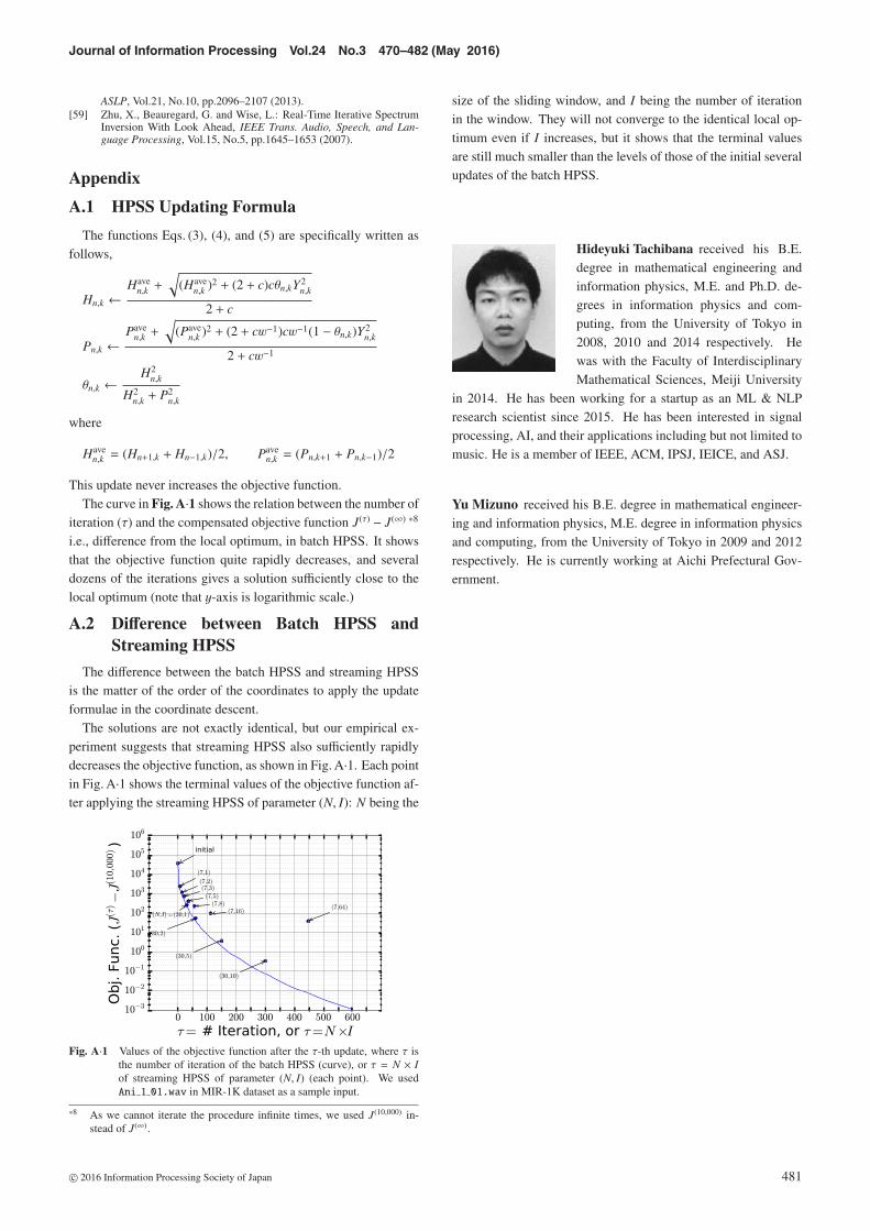
This update never increases the objective function.The curve in Fig. A·1 shows the relation between the number of
iteration (τ) and the compensated objective function J(τ) − J(∞) *8
i.e., difference from the local optimum, in batch HPSS. It showsthat the objective function quite rapidly decreases, and severaldozens of the iterations gives a solution sufficiently close to thelocal optimum (note that y-axis is logarithmic scale.)
A.2 Difference between Batch HPSS andStreaming HPSS
The difference between the batch HPSS and streaming HPSSis the matter of the order of the coordinates to apply the updateformulae in the coordinate descent.
The solutions are not exactly identical, but our empirical ex-periment suggests that streaming HPSS also sufficiently rapidlydecreases the objective function, as shown in Fig. A·1. Each pointin Fig. A·1 shows the terminal values of the objective function af-ter applying the streaming HPSS of parameter (N, I): N being the
Fig. A·1 Values of the objective function after the τ-th update, where τ isthe number of iteration of the batch HPSS (curve), or τ = N × Iof streaming HPSS of parameter (N, I) (each point). We usedAni 1 01.wav in MIR-1K dataset as a sample input.
*8 As we cannot iterate the procedure infinite times, we used J(10,000) in-stead of J(∞).
size of the sliding window, and I being the number of iterationin the window. They will not converge to the identical local op-timum even if I increases, but it shows that the terminal valuesare still much smaller than the levels of those of the initial severalupdates of the batch HPSS.
Hideyuki Tachibana received his B.E.degree in mathematical engineering andinformation physics, M.E. and Ph.D. de-grees in information physics and com-puting, from the University of Tokyo in2008, 2010 and 2014 respectively. Hewas with the Faculty of InterdisciplinaryMathematical Sciences, Meiji University
in 2014. He has been working for a startup as an ML & NLPresearch scientist since 2015. He has been interested in signalprocessing, AI, and their applications including but not limited tomusic. He is a member of IEEE, ACM, IPSJ, IEICE, and ASJ.
Yu Mizuno received his B.E. degree in mathematical engineer-ing and information physics, M.E. degree in information physicsand computing, from the University of Tokyo in 2009 and 2012respectively. He is currently working at Aichi Prefectural Gov-ernment.
c© 2016 Information Processing Society of Japan 481

Journal of Information Processing Vol.24 No.3 470–482 (May 2016)
Nobutaka Ono received his B.E., M.S.,and Ph.D. degrees in Mathematical En-gineering and Information Physics fromthe University of Tokyo, Japan, in 1996,1998, 2001, respectively. He joined theGraduate School of Information Scienceand Technology, the University of Tokyo,Japan, in 2001 as a Research Associate
and became a Lecturer in 2005. He moved to the National In-stitute of Informatics, Japan, as an Associate Professor in 2011.His research interests include acoustic signal processing, specif-ically, microphone array processing, source localization and sep-aration, and optimization algorithms for them. He is the authoror co-author of more than 180 articles in international journal pa-pers and peer-reviewed conference proceedings. He was a Tuto-rial speaker at ISMIR 2010, a special session chair in EUSIPCO2013 and 2015, a chair of SiSEC (Signal Separation EvaluationCampaign) evaluation committee in 2013 and 2015. He was anAssociate Editor of the IEEE Transactions on Audio, Speech andLanguage Processing during 2012 to 2015. He has been a mem-ber of IEEE Audio and Acoustic Signal Processing (AASP) Tech-nical Committee since 2014. He is a senior member of the IEEESignal Processing Society, and a member of the Acoustical So-ciety of Japan (ASJ), the Institute of Electronics, Informationand Communications Engineers (IEICE), the Information Pro-cessing Society of Japan (IPSJ), and the Society of Instrumentand Control Engineers (SICE) in Japan. He received the Sato Pa-per Award and the Awaya Award from ASJ in 2000 and 2007, re-spectively, the Igarashi Award at the Sensor Symposium on Sen-sors, Micromachines, and Applied Systems from IEEJ in 2004,the best paper award from IEEE ISIE in 2008, Measurement Di-vision Best Paper Award from SICE in 2013, the best paper awardfrom IEEE IS3C in 2014, the excellent paper award from IIHMSPin 2014 and the unsupervised learning ICA pioneer award fromSPIE.DSS in 2015.
Shigeki Sagayama received his B.E.,M.E. and Ph.D. degrees from the Univer-sity of Tokyo, Japan in 1972, 1974 and1998, respectively, all in mathematicalengineering and information physics. Hejoined Nippon Telegraph and TelephonePublic Corporation (currently, NTT) in1974 and started his career in speech anal-
ysis, synthesis and recognition at NTT Labs in Musashino, Japan.From 1990, he was Head of Speech Processing Department, ATRInterpreting Telephony Laboratories, Kyoto, Japan to pursuean automatic speech translation project. From 1993, he wasresponsible for speech recognition, synthesis and dialog systemsat NTT Human Interface Laboratories, Yokosuka, Japan. In1998, he became a professor of Graduate School of InformationScience, Japan Advanced Institute of Science and Technology(JAIST), Ishikawa, Japan. In 2000, he was appointed Professor,Graduate School of Information Science and Technology, theUniversity of Tokyo, Japan. He is an author or co-author of ap-proximately 700 technical papers on processing and recognitionof speech, music, acoustic signals, hand-writing and images.Prof. Sagayama received National Invention Award from theInstitute of Invention of Japan in 1991, Chief Officials Awardfor Research Achievement from the Science and TechnologyAgency of Japan in 1996 and other academic awards includingPaper Awards from the Institute of Electronics, Information andCommunications Engineers, Japan (IEICEJ), in 1996 and fromInformation Processing Society of Japan (IPSJ) in 1995. Heis the Chair of IEEE Signal Processing Society Japan paper, afellow of IEICEJ and a member of ASJ (Acoustical Society ofJapan) and IPSJ.
c© 2016 Information Processing Society of Japan 482