Embed Size (px)
Citation preview

I J C T A, 9(16), 2016, pp. 8225-8233© International Science Press
A Reactive Planning based Guidance forVisually Challenged using Depth MapRamanathan L.* and Senthilnathan R.**
ABSTRACT
Visual information is very essential for navigation oriented tasks, but visually challenged individuals face difficultiesin performing these tasks since they lack sufficient information regarding their surrounding environment. Manyvision and non-vision based aids have been proposed in literature to aid the blind for navigation and perception ingeneral. The proposed system aims to a provide reactive planning method using a depth map acquired from a visionsystem, to assist visually challenged individuals in achieving collision-free navigation in an indoor environment.Understanding the environment in front involves two phases. Firstly, classifying the obstacles as static or dynamicwill help us identify the obstacles that require quick response. Secondly, the velocity of the obstacles are estimatedfrom the depth map which gives information whetherthey are approaching or moving away. Once understanding theenvironment in front is carried out in terms of its geometry, navigation planning is done to guide the user who holdsthe differential drive robot attached to the walking stick.
Keywords: component; Visual aid; Kinect; Depth map; Obstacle avoidence; Cane; Visually blind; Navigation task.
1. INTRODUCTION
According to WHO, as of 2012 there were 285 million people who were visually impaired of which 246million had low vision and 39 million were blind [1]. People with complete blindness or low vision oftenhave a constraint in self-navigating outside well-known environments. Hence, many people with low visionneed a sighted friend or family member to navigate in anunknown environment. Also, blind people need tolearn every detail about their home environment. Large obstacles such as tables and chairs must remain inone location to prevent injury. When a blind person lives with others, each member of the household mustdiligently keep the walkways clear and all the items in their designated locations. One of the commonlyused tool to assist blind people is a walking stick which is very cheap and simple yet, an efficient andareliable aid. But it provides only the tactile information of the ground and not the speed, velocity ordistance from the obstacle which are usually gathered by visual perception for the sake of uninterruptedlocomotion. On the other hand, guide dogs are also used to help the blind users to navigate, but the availabilityof the guide dogs are very fewdue to the large amounts of time involved in training them. Many methodologiesin assistive technology have been implemented to help the visually challenged individuals achieve varioustasks. Passenger bus alert system was reported in [2]. The blind people in the station are provided with awireless communication unit which is recognized by the module in the transportation unit and the indicationis made in the vehicle that the blind people are present in the station. This enables in halting of the vehiclein the desired location. The desired vehicle that the blind want to take is notified to him with the help ofspeech recognition system. The blind peopleinput their destination using a microphone and the voicerecognition system recognizes it and notifies them once the destination arrives. Currency Note Recognizer(CNR) for the Visually Impaired was published in [3]. It detects different colors of the currency notes andoutputs various beeping sound patterns to indicate the value of that currency. Although various aidshave
* Department of Mechanical Engineering, SRM University, Kattankulathur, Chennai, India, Email: [email protected]
** Department of Mechatronics Engineering, SRM University, Kattankulathur, Chennai, India, Email: [email protected]
8226 Ramanathan L. and Senthilnathan R.
been addressed by the researchers for the visually impaired, the most challenging task is to achieve collisionfree navigation.
A simple navigation aid for visually challenged named NAVI [4] was implemented. In [4], instead ofusing a depth information, the raw image is subsampled and taken for further processing. Then using afuzzy Learning Vector Quantization (LVQ) neural network the pixels are classified as background orforeground based on various features. Then the background pixels are suppressed and finally they aretransformed into stereo sound starting from the top left to the bottom right of the image. These stereo soundare transmitted to the user as an information about the environment. Blind people were trained to identifythe obstacles from the sound. Thus it was used only to identify the obstacle in front but it does not give anyinformation regarding the distance from the obstacle which is very important to achieve collision freenavigation. Similar to NAVI, the Voice [5] takesthe image and directly converts them into sound based onthe grey levels on the image. This also required extensive training which made it very difficult to use. Amobility aid inspired by the bat’s navigation of echolocation was developed in [6]. Ultra sonic sensor wasused to gather the depth information from the environment. Similar work was done in [7] using the ultrasonicsensor. Both had limitations due to the characteristics of the ultrasound reflections. Many obstacleswhichhave very small or soft surfaces can barely be detected, and also they have a very limited range.
Reactive planning for a visually impaired individual should be done by considering the various parameterssuch as walking speed of the user, environment in which the user is engaging, distance from the obstacle,shape and dimension of the obstacle, velocity of the obstacle, characteristics of the surface, etc. In thecurrent research a robot is used to guide the user. Thus the turning radius and the speed of the robot must bein accordance with the maneuvering ability of the user. Then these information must be converted in a waythat a blind user can understand. Voice feedback is one of the commonly used techniques. A wearablesystem that assists the blind people orienting themselves in an indoor environments was developed in [8].It has a text-to-speech device and a loudspeaker which guides the user with the synthesized voice. A majordisadvantage in the voice feedback is that, it will make the user deaf to environmental sounds which mightcause an accident (vehicle horn). Another efficient technique is the tactile feedback system which will notinterfere with the environmental sounds. It sends information to the user mostly through vibration. Aninexpensive, wearable and low power device that will transform depth information (output of stereo cameras)into tactile information for use by visually impaired people during navigation was developed in [9]. Itconsists of a pair of gloves with piezo vibrators for each finger. Depending upon the vibration of the fingerthe user is guided. A Co-Robotic Cane(CRC) method was implemented in [10] which was inspired fromtraditional canes which have a rolling tip that rotates. Upon hitting on the ground, it will rotate in the eastor west direction, thereby guiding the user in the desired direction. It will not rotate when the user needs tomove forward. The CRC uses a 3D camera for both pose estimation and object recognition in an unknownindoor environment. In current work, a similar technique is used, in which a robotic walking stick will pullthe user in the required direction. It mimics a dog which guides the user in an obstacle free direction.
2. DEPTH PERCEPTION
Depth perception is the ability to perceive the world in three dimensions. It can be done using various cuessuch as binocular cues and monocular cues. Each cue can be further divided in to many sub categories. Thesub category of binocular cues include stereopsis, convergence, and shadow stereopsis. In case of monocularcues some of the subcategories are depth from motion, perspective, relative size, familiar size, occlusion,lighting and shadows, defocus blur and elevation. Humans use different types of cues at the same time.Human brain is trained to select the best cue for depth perception based on the environment without beingaware of the change. In case of mobile robots, various methodologies are used to perceive the depth of theenvironment. Active time of flight techniques, depth from focus, depth from defocus, depth from perspectiveare some of the depth perception techniques. Among them stereo technique is the most commonly used.

A Reactive Planning based Guidance for Visually Challenged using Depth Map 8227
Virtual acoustic space technique was published in [11] which creates a sound map of the environmentby using a stereo camera attached to the eye glasses. Major drawback was implementing it in real-time dueto extensive processing required to formulate the depth image. Several papers were published using thesame stereo technique but with better results. Stereo technique is implemented in real-time in this paper[12] but with the assumption that the height of the obstacles in front of the user is known in prior and inwhich the major task was to determine the surface conditions such as curbs, staircase and other generalobstacles encountered in the navigational path. Thus the stereo correspondence problem makes this techniquedifficult to implement in real-time without any assumption.
2.1. Kinect for Depth Perception
RGBD cameras can also be used to calculate the depth of the environment. These cameras consist of anInfrared (IR) sensor, an IR projector and a RGB camera. The IR projector projects a known pattern on theenvironment and the IR sensor receives the reflected pattern from the environment. Based on thetransformation between the observed pattern and the known pattern the depth is calculated. Since it usesIR, it has an advantage of working equally efficient in no visible light condition. This technique is efficientwhen compared to the stereo technique which was discussed in the previous section, since it doesn’t involveany expensive algorithm in estimating the depth map. Microsoft Kinect is one of the most commonly usedRGBD cameras. The Kinect sensor was originally designed to be used to control games on the MicrosoftXbox 360 gaming console. Instead of using a controller, users were able to play the game using their handswith the help of the Kinect sensor. Apart from gaming applications, multiple libraries are available whichmakes it a potential candidate in computer vision. The pixels in the depth map give the relative depthinformation between the obstacles and the camera. Google uses similar RGBD cameras in project Tango[13] to estimate the depth of the environment. Project Tango technology gives a mobile device the ability tonavigate the physical world similar to humans. Project Tango brings a new kind of spatial perception to theAndroid device platform by adding advanced computer vision, image processing and special vision sensors.Project Tango devices can use visual cues to help recognize the world around the user. They can self-correct errors using motion tracking and localize themselves in areas they’ve seen before.
Though Kinect has many advantages than the stereo technique, it has its own downside. Depthinformation obtained from the region exposed to sunlight or covered by water will not give an accuratemeasurement of depth. Thus the prototype was restricted to an indoor environment. Another limitation isthat the device has to be plugged in to the computer all the time for data acquisition which makes it difficultin terms of portability. This limitation is handled by using a light weight, standalone processor such asJetson TK1. A wearable RGBD indoor navigation system for the blind was implemented in [14] along withthe tactile feedback system. In this method the user has to carry the laptop and other components in thebackpack during navigation. In the current work, to avoid the user carrying extra load, the processor andthe RGBD camera are placed in the differential robot attached to the lower end of the walking stick. Thusthe user is free to walk while the differential robot will navigate the user without any collision.
The RGB camera in the Kinect sensor is of resolution 1280×960. The depth map obtained from the IRcamera and the projector is of resolution 640×480. The Kinect sensor is tested for the minimum distancethat is required for the IR wave to reach the receiver, which was found to be 58cm. Similarly, the maximumoptimum distance was found to be 400cm. The above values are obtained from the experiment which isdiscussed in detail in the upcoming section.
2.2. Experimental Setup
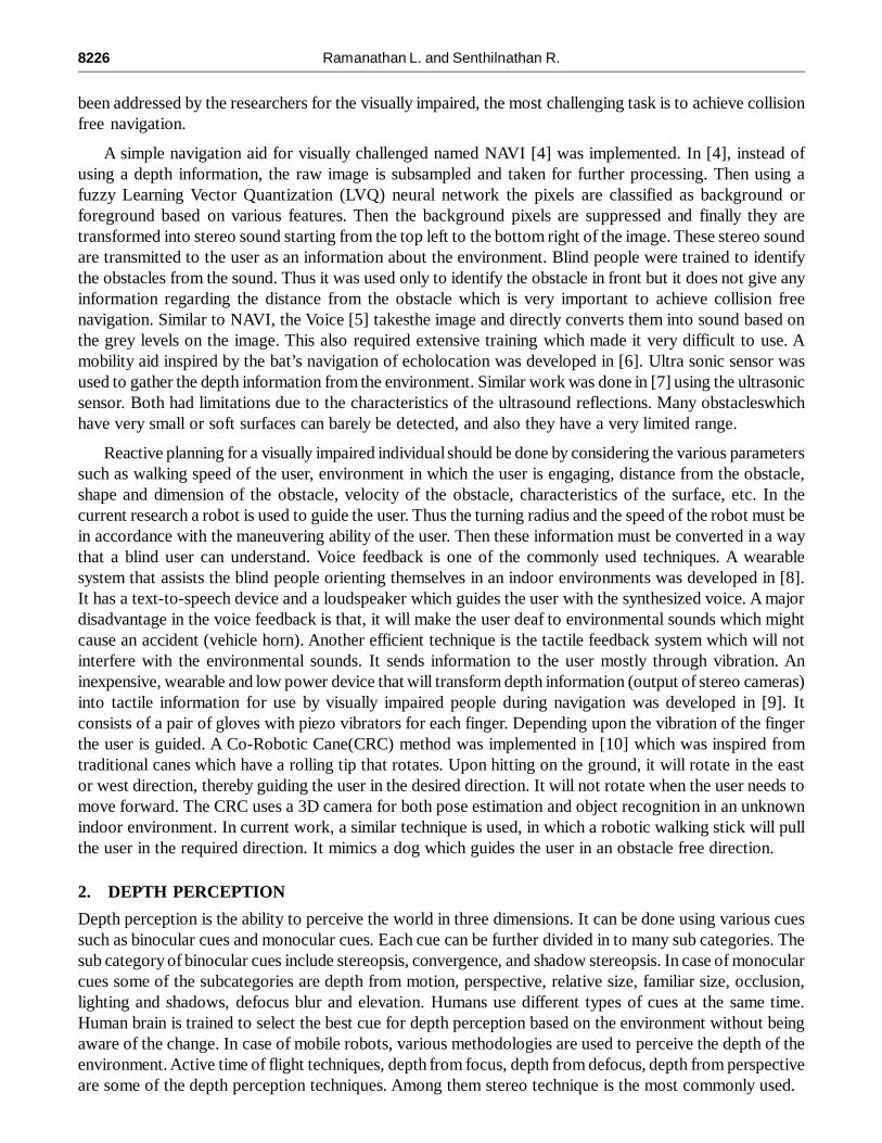
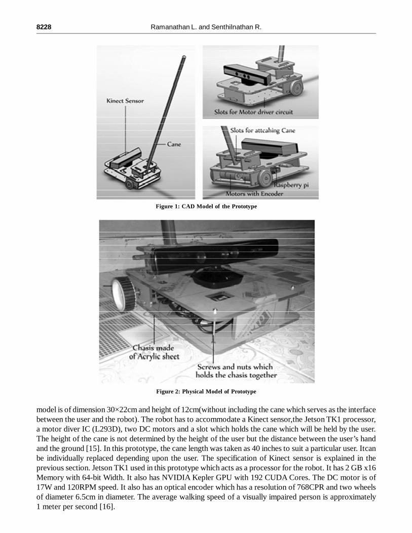
The CAD model of the prototype is done in Solidworks 2013 which is shown in Fig. 1. Fabrication of therobot was done using the acrylic sheet of 6mm thickness. Laser cutting method was adopted to cut theacrylic sheet in the required dimension. The physical model of the robot is shown in Fig. 2. The physical
8228 Ramanathan L. and Senthilnathan R.
model is of dimension 30×22cm and height of 12cm(without including the cane which serves as the interfacebetween the user and the robot). The robot has to accommodate a Kinect sensor,the Jetson TK1 processor,a motor diver IC (L293D), two DC motors and a slot which holds the cane which will be held by the user.The height of the cane is not determined by the height of the user but the distance between the user’s handand the ground [15]. In this prototype, the cane length was taken as 40 inches to suit a particular user. Itcanbe individually replaced depending upon the user. The specification of Kinect sensor is explained in theprevious section. Jetson TK1 used in this prototype which acts as a processor for the robot. It has 2 GB x16Memory with 64-bit Width. It also has NVIDIA Kepler GPU with 192 CUDA Cores. The DC motor is of17W and 120RPM speed. It also has an optical encoder which has a resolution of 768CPR and two wheelsof diameter 6.5cm in diameter. The average walking speed of a visually impaired person is approximately1 meter per second [16].
Figure 1: CAD Model of the Prototype
Figure 2: Physical Model of Prototype

A Reactive Planning based Guidance for Visually Challenged using Depth Map 8229
By multiplying perimeter of wheel and RPM of motor, obtained speed is 40.84cm per second which is60% less than the average speed but it is acceptable since it is an indoor environment. The speed can beincreased by using wheels of higher diameter or by using a motor with higher RPM. The whole system ispowered by a 12V rechargeable lead acid battery with proper adaptors for each component. The computerused in this project has a configuration of 4 GB random access memory, 1 GB graphic card, Ubuntu 14.04operating system and Intel i3 processor. The algorithms are written in python 2.7 with libraries such asopencv2, freenect (for accessing Kinect in python) and few other commonly used libraries. The distancebetween the robot and the user must also be taken into account to make the user comfortable while walking.The average distance between two feet while walking is 25cm. The prototype was first experimented withraspberry pi with was slow in processing [19].
3. OBSTACLE CLASSIFICATION
The obstacle in-front must be identified whether it is moving towards are away from the user, by which theobstacles can be prioritized to find the one which needs quick reaction. The depth image obtained from theKinect sensor will be noisy and also for range less than 58cm, the data is invalid because the IR gettingreflected from a short distance will not be focused into the receiver. The longest range which has beentested for this sensor is 400cm, above which the intensity of the reflected IR will not be enough to producea proper output. Thus the data is restricted between the ranges for correctness.
3.1. Walls and Floors Suppression
In the depth image, the obstacle should be identified without interfering with the walls or the floors. Sincethe sensor is placed close to the surfaces the depth value will indicate that theyare very close to the robot.Thus the region which contains walls and floors must be suppressed in order to segment the obstacle. Asimple method implemented to tackle this issue is to eliminate the 10% rows and columns from all fourboundaries [17] of the depth image. On the other hand, the standard deviation of the pixel values in each ofthe rows and columns from the boundary will give some idea regarding the walls and the floors. If the
Figure 3: Depth Gradient
Figure 4: Difference Image and Morphological Image

8230 Ramanathan L. and Senthilnathan R.
standard deviation is very low then it signifies the presence of floors at the bottom rows or walls at thecolumns, as they have a uniform depth value along the row or column. In most cases the obstacle canoccupy an entire row, then they also will give low standard deviation. In order to eliminate this scenario, therate of change of depth from all of the four boundaries is calculated. The floors and walls will have increasingdepth values and thus the change of depth across rows will be a constant. Thus from the boundary, differencebetween the consecutive rows are found. If the difference is found to be uniform in the entire row then itcorresponds toa floor (it is repeated for columns in case of walls). The change in depth along the arrowshown in Fig. 3 will be a constant since it is a wall. If there are any changes in the difference between theconsecutive rows or columns, it indicates the presence of an obstacle which should be taken into account.The RGB version of the environment is also shown for better understanding. In a narrow path, single rowwill have a floor and also side walls, taking standard deviation will give high value whereas taking changeof depth across each of the rows and columns will not be a constant value. Taking standard deviation orfinding the change in depth along the dashed line shown in Fig. 3 will not give proper solution whether it isan obstacle or a wall or a floor. Thusto tackle this problem, the obstacle is first cropped out then it undergoesanother test where the change in depth in those obstacle is calculated, if the change is high then thoseregion might be a wall or a floor which can be suppressed.
For identifying the approaching obstacle, difference of the current and previous depth map values iscalculated. While finding difference, the positive values indicates the presence of approaching obstacle and
Figure 5: Obstacle Classification.
Figure 6: Distance versus Spatial Resolution and Pixel Values in the Depth Map

A Reactive Planning based Guidance for Visually Challenged using Depth Map 8231
negative values indicate thepresence of departing obstacle with respect to the user. Ideally the difference ofthe current and previous depth must be null for a static scene. But the difference will be nonzero due to theerror as shown in Fig. 4. These errors will be in a wave like pattern which is due to the reflection delay ofthe IR wave. These must be eliminated in order to classify the obstacle. Applying the morphological operationswill eliminate these errors but it will introduce blocks depending upon the kernel selected. These blockswill reduce the sharpness of edges in the obstacle which is acceptable for obtaining the obstacle location.The static obstacle is shown in the black bounding box and the approaching obstacle is shown in the greybounding box in Fig. 5.
3.2. Scalling Effect
The average walking speed of a visually impaired person is approximately 1 meter per second [16] and theyrequire a reaction time of 1.5 seconds. The maximum distance for obstacle detection should not be morethan 1.5 meter [16] in case of static obstacles. In the current work, since the robot in-front is taking care ofobstacle detection the maximum distance for obstacle detection must be 150 cm from robot, thus 200cm(30cm is the space occupied by the robot, remaining is left free for clearance between the robot and theuser) from the foot of the user in case of static obstacles. On the other hand, dynamic obstacles that movewith higher velocity need to be known in prior distance to make necessary action. Also analyzing all theobstacles in the environment will be a redundant process. Monitoring an obstacle which is having eitherstatic or dynamic characteristics at a farther distance is not necessary until it comes within the desiredregion. Thus a threshold is fixed, above which the movement of the obstacle is not taken into account. Theregion within the threshold is termed as response region. In Fig. 7 two people are walking towards thesensor, while it identifies only the first person because he is within the response region. The threshold forresponse region was fixed in this case as 300cm form the robot after conducting a few experiments.
An experiment was carried out to understand the behavior of Kinect sensor to obstacles at variousdistances. The sensor was mounted on a horizontal plane and a cardboard box of dimension 15×38 cm isplaced before the sensor at different distances to obtain the corresponding depth value given by the sensor.A graph was plotted for the distance versus the average pixel value of the cardboard box in the depth mapwhich is shown in Fig. 6. Obtaining the absolute velocity and distance is difficult due to the non-linearcharacteristics of the graph.
But only the relative depth change in consecutive frames are considered. The graph also shows thedistance versus the spatial resolution of depth map. It is inferred that, as the distance increases the dimensionoccupied by a pixel increases linearly.
4. MAPPING MODULE
As the user navigates the environment depth information is obtained from the Kinect sensor which can beaggregated to build a map. It will help the user to understand the environment in an efficient manner. As
Figure 7: Scaling Effect

8232 Ramanathan L. and Senthilnathan R.
mentioned before, the depth information obtained from the Kinect sensor shares a non-linear relationshipwith the actual depth information. Thus, the dimensions shown in the map will not give the estimate ofabsolute distance which can be obtained after fixing the non-linearity in the depth value. The equation ofthe nonlinear curve is calculated by the values obtained from the experiment. The obtained equation is usedto fix the nonlinearity in the depth value. The major problem is to convey the map information to the user.The popular feedback methods are through sound and vibrations. Conveying a map in audio format willmake it impossible for the user to understand and vibration technique also suffersa similar limitation. Inorder to face this limitation, we can use refreshable braille display to convey the map information.
Braille [18] is a tactile writing system used by people who are blind or visually impaired. A blind userwill be able to understand the characters by touching it. The electronic braille displays are available whichcan actuate the dots in the display up and down based on the information fed to them. Thus, we can feed themap to the display and the user will understand the environment by touching them in a better manner. Sincethe refreshable Braille display is of two dimensions, the map must be converted to the same format.Thus,the depth information can be converted to a top view 2D format before feeding to the display.
The depth information obtained from Kinect has three-dimensional information with the front view.The information has to be transformed into a top view format so that it can be fed to the refreshable Brailledisplay. By simple matrix rotation, we can achieve top view map where the height is suppressed due to thelimitation of the Braille display. As the user navigates, the map must be updated. To achieve this task theodometric calculation is done in a robot with the help of the optical encoder attached to the motor. Thedepth value up to 200 cm is taken into account for single depth map and when the robot has crossed 150cmin any direction the next depth map is taken for updating the map. This enables the map to update in asmoother and less noise manner. The odometric calculation is used to transform the depth map relative tothe initial position and it is appended in the map by which we can obtain the whole map of the environment.The user will now get an overview of the environment by touching the braille display. Fig. 8shows the frontview (left image) and the transformed top view of the same depth map (right image).
5. CONCLUSION AND FUTURE WORK
A prototype of a visual aid is developed which will help the visually impaired to navigate the environmentwithout any collision. The prototype is best applied toindoor environment which has a flat and hard, whichis suited to wheeled robots. In this paper the issue of understanding the obstacle’s geometry which will helpin reaction planning is addressed. Detailed understanding of the obstacles such as situations involvingocclusion, close proximity of more than one obstacle etc. are to be addressed as part of the future work. Theprototype does not add any extra load to the user because all the components are fixed in the robot itself. Areal world implementation may be addressed with fewer assumptions in future, so that the computationdoes not project any unexpected behaviors or latency. Currently, the system works offline with the pre-
Figure 8: Top View Map Generation

A Reactive Planning based Guidance for Visually Challenged using Depth Map 8233
captured depth data. Kinect sensor shall be mounted onto the robot and it will be integrated with the JetsonTK1 to make it portable. Further, a module to calculate the odometry can be implemented as a result ofwhich the robot will be able to know its location relative to the initial position. Also by combining the depthdata with the odometric value, a 3D map can be built which will makes it easier for the user to recognize aparticular room and also reach a desired landmark in the map. This can further be extended to learning sothat additional features such as letting the user know the locations previously navigated may be incorporated.
REFERENCES[1] Visual impairment and blindness Fact Sheet N282, August 2014, [Online].Available:http://www.who.int/mediacentre/
factsheets/fs282/en
[2] G. Lavanya, W. Preethy, A. Shameem and R. Sushmitha, “Passenger bus alert system for easy navigation of blind,” inCircuits, Power and Computing Technologies(ICCPCT), 2013 International Conference on, March 2013, pp. 798-802.
[3] A. Mohamed, M. Ishak, and N. Buniyamin, “Development of a Malaysian currency note recognizer for the vision impaired,”in Engineering andTechnology (S-CET), 2012 Spring Congress on, May 2012, pp. 1–4.
[4] G. Sainarayanan, R. Nagarajan, and S. Yaacob, “Fuzzy image processing scheme for autonomous navigation of humanblind,” Applied Soft Computing, vol. 7, no. 1, pp. 257–264, 2007. [Online].Available:http://www.sciencedirect.com/science/article/pii/S1568494605000670
[5] P. Meijer, “An experimental system for auditory image representations,” Biomedical Engineering, IEEE Transactions on,vol. 39, no. 2, pp. 112–121, Feb 1992.
[6] T. Ifukube, T. Sasaki, and C. Peng, “A blind mobility aid modeled after echolocation of bats,” Biomedical Engineering,IEEE Transactions on, vol. 38, no. 5, pp. 461–465, May 1991.
[7] M. Bousbia-Salah, A. Redjati, M. Fezari, and M. Bettayeb, “An ultrasonic navigation system for blind people,” in SignalProcessing and Communications, 2007. ICSPC 2007. IEEE International Conference on, Nov 2007, pp. 1003–1006.
[8] A. Hub, J. Diepstraten, and T. Ertl, “Design and development of an indoor navigation and object identification system forthe blind,” in Proceedings of the 6th International ACM SIGACCESS Conference on Computers and Accessibility, ser.Assets ’04. New York, NY, USA: ACM, 2004, pp. 147–152. [Online]. Available: http://doi.acm.org/10.1145/1028630.1028657
[9] J. Zelek, R. Audette, J. Balthazaar, and C. Dunk, “A stereo-vision system for the visually impaired,” Tech. Rep., 2000.
[10] C. Ye, S. Hong, and X. Qian, “A co-robotic cane for blind navigation,” in Systems, Man and Cybernetics (SMC), 2014IEEE International Conference on, Oct 2014, pp. 1082–1087.
[11] J. L. Gonz´alez-Mora, A. Rodr´ýguez-Hern´andez, L. F. Rodr´ýguez-Ramos, L. D´ýaz-Saco, and N. Sosa, EngineeringApplications of Bio-Inspired Artificial Neural Networks: International Work-Conference on Artificial and Natural NeuralNetworks, IWANN’99 Alicante, Spain, June 2–4, 1999 Proceedings, Volume II. Berlin, Heidelberg: Springer BerlinHeidelberg, 1999. “Development of a new space perception system for blind people, based on the creation of a virtualacoustic space”,pp.321–330.
[12] V. Mohandas and R. Paily, “Stereo disparity estimation algorithm for blind assisting system,” CSI Transactions on ICT,vol. 1, no. 1, pp. 3–8, 2012.
[13] Project Tango, Mobile 3D technology. [Online]. Available: https://www.google.com/atap/project-tango
[14] Y. H. Lee and G. Medioni, Computer Vision - ECCV 2014 Workshops: Zurich, Switzerland, September 6-7 and 12, 2014,Proceedings, Part III. Cham: Springer International Publishing, 2015, ch. Wearable RGBD Indoor Navigation System forthe Blind, pp. 493–508.
[15] Walking stick measurement for all users by classic cane, http://www.classiccanes.co.uk/catalogue/Stick_Measurement.html.
[16] S. Vorapatratorn and K. Nambunmee, “isonar: an obstacle warning device for the totally blind,” Journal of AssistiveRehabilitative and Therapeutic Technologies, vol. 2, no. 0, 2014.
[17] V. Filipe, F. Fernandes, H. Fernandes, A. Sousa, H. Paredes, and J. Barroso, “Blind navigation support system based onMicrosoft kinect,” Procedia Computer Science, vol. 14, pp. 94 – 101, 2012, proceedings of the 4th International Conferenceon Software Development for Enhancing Accessibility and Fighting Info-exclusion (DSAI 2012).
[18] Becker Deceased. V, Becker Legal Representative John David A. (late of New York;Brooklyn, NY), Hinton, Daniel E.(Arnold, MD), Anderson Jr., Hugh G. (Westminster, MD), “Braille computer monitor,” no. 6700553, March 2004. [Online].Available: http://www.freepatentsonline.com/6700553.html
[19] L. Ramanathan and R. Senthilnathan, “Depth Map Based Reactive Planning to Aid in Navigation for Visually Challenged,”in 2nd IEEE International Conference on Engineering and Technology (ICETECH), Coimbatore, 2016.