Embed Size (px)
Citation preview

CYBERNETICS AND PHYSICS, VOL. 10, NO. 1, 2021, 5–8
A RANDOM SIGNAL GENERATOR BY USING ANALOGELECTRONICS
Leonardo AchoDepartment of Mathematics
Polytechnic University of Catalunya (UPC)Campus Terrassa
Spainemail:[email protected]
Article history:Received 21.12.2020, Accepted 17.06.2021
AbstractThe describing function theory is a powerful mathe-
matical tool to predict oscillations in non-linear dynam-ical systems. This theory is here invoked to design arandom signal generator and realized by using analogelectronic elements. Then, and according to experimen-tal results, histograms of the resultant signal are shownalong with the generated signal in the time domain. Fi-nally, the proposed electronic circuit is simple and cheapto construct.
Key wordssignal generator, electronics, random behaviour
1 IntroductionA random signal generator can be interpreted as an
oscillator device but producing a random signal insteadof a periodic one. This includes the chaotic oscillatorsystems. [Buchovecka et al., 2017; Vazquez-Medinaet al., 2009]. Moreover, many chaotic oscillator circuitshave been recently reported [Minati et al., 2020; Zhouet al., 2015; Piper and Sprott, 2010; Karakaya et al.,2019]. The design of these systems is based on thetheory of chaotic dynamical models. Furthermore,some chaotic oscillators are too complex to implementbecause some of them use analog signal multipliers.[Yildirim and Kacar, 2020; Pham et al., 2017]. Incontrast, there is a simple chaotic circuit but required touse of inductors. [Wu, 1987].
On the other hand, the describing function theory topredict oscillations in a dynamical system [Slotine et al.,1991] can also offer an option to design random signalgenerators. Hence, the main objective of this paper is to
propose a novel random generator circuit by using thedescribing function framework. Besides, the resultantcircuit is simple and easy to construct. Accordingto experimental results, this circuit demonstrates thedesired behavior. Experimental signals and histogramsare shown to support our main contribution.
The rest of the paper is organized as follows. Section2 introduces the basics of describing function theory topredict an oscillation behavior in a nonlinear dynamicalsystem. Then, a simple analog electronic circuit toproduce a random signal is conceived and shown inSection 3. Experimental results are also evidenced.Finally, in Section 4, the final remarks are written.
2 Describing FunctionAs was previously mentioned, the describing func-
tion analysis is a well-known mathematical frameworkto predict an oscillation behavior by a kind of nonlinearsystem [Slotine et al., 1991]. Basically, if a nonlinearsystem can be represented as in Figure 1, then an oscil-lating output will be observed if the following assump-tions are confirmed [Slotine et al., 1991; Khalil and Griz-zle, 2002; Garber and Rozenvasser, 1965; Zaitceva andChechurin, ]:
1. The nonlinear element is a single element.
2. The nonlinear element is a time-invariant one.
3. The linear system has a limited frequency band-width response.

6 CYBERNETICS AND PHYSICS, VOL. 10, NO. 1, 2021
Figure 1. A nonlinear dynamical system also known as a system inthe Lurie format. r := r(t) = 0 represents a system in which itsdynamical behavior depends on itself..
In other words, an oscillating signal will be presented atthe system output in Figure 1 if the nonlinear elementpresents saturation and the linear system is a kind oflow pass filter. [Slotine et al., 1991]. For instance,operational amplifiers and transistors operated by aDC power source present saturation and have limitedfrequency bandwidth operation. Hence, these electronicelements satisfy some of the previous cited assumptions.
3 A Random Signal Generator CircuitBased on the describing-function presentation in Sec-
tion 2, we propose the circuit diagram given in Figure 2.Therefore, in this circuit, we have:
1. The given operational amplifier supplies the re-quired negative feedback to the rest of the electronicsystem. Additionally, this amplifier has a finitefrequency bandwidth response too.
2. The transistors have the needed saturation effect.These also produce a mixing combination of thefeedback signal from the operational amplifierand are manipulated by the capacitors to thesetransistors.
3. The potentiometer connected to the operationalamplifier is employed to tune the circuit. This po-tentiometer introduces a direct current componentto the output signal of the operational amplifierto overcome the single polarity of the DC powersupply. As a consequence of this, the outputresponse of the circuit is linked to this parameter.
Additionally, Figure 3 shows a photo of the circuit re-alization for experiments.
Figure 2. A random signal generator circuit. The resistances are inohms and capacitors in microfarads. Hence, for instance, the resistanceof 330 means 330 ohms, and the capacitor 1 means 1 microfarad, andso on.
Figure 3. A photo of the schematic circuit realization.
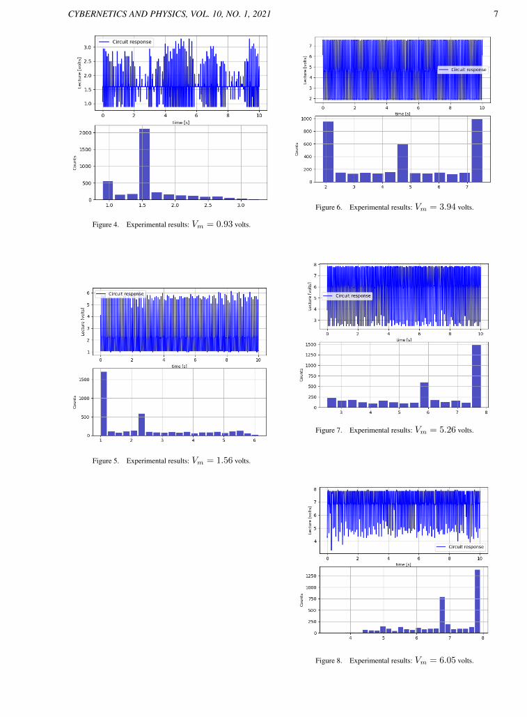
4 Experimental ResultsThis section displays the experimental results of our
electronic circuit realization on generating a random sig-nal. The response signal at the output of the operationalamplifier element is then measured by using a computerdigital oscilloscope. Therefore, a signal sample set isregistered by varying the potentiometer in the circuitshown in Figure 2. Hence, the voltage generated by thispotentiometer at its central pin, and here named as Vm,is read to label the potentiometer action to each outputoutcome and presented in Figures 4 to 9. For each onefigure, there is the related signal and its histogram.
CYBERNETICS AND PHYSICS, VOL. 10, NO. 1, 2021 7
Figure 4. Experimental results: Vm = 0.93 volts.
Figure 5. Experimental results: Vm = 1.56 volts.
Figure 6. Experimental results: Vm = 3.94 volts.
Figure 7. Experimental results: Vm = 5.26 volts.
Figure 8. Experimental results: Vm = 6.05 volts.

8 CYBERNETICS AND PHYSICS, VOL. 10, NO. 1, 2021
Figure 9. Experimental results: Vm = 6.53 volts.
5 ConclusionA simple and low-cost electronic circuit design to
produce a random signal was proposed. Additionally,a potentiometer was included to tune this signal forfurther reading. To note, by changing the capacitors datalinked to the related transistors, other kinds of randomsignals are possible. This offers more further optionson the proposed circuit design. Finally, to highlightthat the histogram given, for instance, in Figure 6,resembles the one reported in [Evangelista et al., 2017].In other words, the generated random signal may be achaotic one, but we decided not to test it as a chaoticsignal. Finally, and related to cybernetic systems,our approach uses feedback to an electronic circuit toproduce a self-sustained dynamic response. This maybe a cybernetic method.
AcknowledgementsThis research was completely funded by the Span-
ish Ministry of Economy and Competitiveness (StateResearch Agency of the Spanish Government)/FondosEuropeos de Desarrollo Regional (MINECO/FEDER),grant number DPI2015-64170-R.
ReferencesBuchovecka, S., Lorencz, R., Kodytek, F., and Bucek, J.
(2017). True random number generator based on ringoscillator puf circuit. Microprocessors and Microsys-tems, 53, pp. 33–41.
Evangelista, J. V., Artiles, J. A., Chaves, D. P., and Pi-mentel, C. (2017). Emitter-coupled pair chaotic gener-ator circuit. AEU-International Journal of Electronicsand Communications, 77, pp. 112–117.
Garber, E. and Rozenvasser, E. (1965). The investiga-tion of periodic regimes of nonlinear systems on thebasis of the filter hypothesis(periodic regimes of non-linear systems investigated on basis of filter hypothe-sis). AUTOMATION AND REMOTE CONTROL, 26,pp. 274–285.
Karakaya, B., Gulten, A., and Frasca, M. (2019). A truerandom bit generator based on a memristive chaoticcircuit: Analysis, design and fpga implementation.Chaos, Solitons & Fractals, 119, pp. 143–149.
Khalil, H. K. and Grizzle, J. W. (2002). Nonlinear sys-tems, vol. 3. Prentice hall Upper Saddle River, NJ.
Minati, L., Gambuzza, L., Thio, W., Sprott, J., andFrasca, M. (2020). A chaotic circuit based on a phys-ical memristor. Chaos, Solitons & Fractals, 138,pp. 109990.
Pham, V.-T., Akgul, A., Volos, C., Jafari, S., and Kapi-taniak, T. (2017). Dynamics and circuit realization ofa no-equilibrium chaotic system with a boostable vari-able. AEU-International Journal of Electronics andCommunications, 78, pp. 134–140.
Piper, J. R. and Sprott, J. C. (2010). Simple autonomouschaotic circuits. IEEE Transactions on Circuits andSystems II: Express Briefs, 57 (9), pp. 730–734.
Slotine, J.-J. E., Li, W., et al. (1991). Applied nonlinearcontrol, vol. 199. Prentice hall Englewood Cliffs, NJ.
Vazquez-Medina, R., Dıaz-Mendez, A., del Rıo-Correa,J., and Lopez-Hernandez, J. (2009). Design of chaoticanalog noise generators with logistic map and mos qtcircuits. Chaos, Solitons & Fractals, 40 (4), pp. 1779–1793.
Wu, S. (1987). Chua’s circuit family. Proceedings of theIEEE, 75 (8), pp. 1022–1032.
Yildirim, M. and Kacar, F. (2020). Chaotic circuitwith ota based memristor on image cryptology. AEU-International Journal of Electronics and Communica-tions, 127, pp. 153490.
Zaitceva, I. and Chechurin, L. The estimation of aircraftcontrol system stability boundaries by the describingfunction method, cybernetics and physics, 2020, vol.9, no. 2. URL: https://doi. org/10.35470/2226-4116-2020-9-2-117-122, pp. 117–122.
Zhou, W.-j., Wang, Z.-p., Wu, M.-w., Zheng, W.-h., andWeng, J.-f. (2015). Dynamics analysis and circuit im-plementation of a new three-dimensional chaotic sys-tem. Optik, 126 (7-8), pp. 765–768.