Embed Size (px)
Citation preview

A publication of the James F. Lincoln Arc Welding Foundation

The James F. Lincoln Arc Welding Foundation cele-brates its 65th birthday this year. Far from preparing toretire, the Foundation is actually reinvigorated with anew sense of purpose and energy. We remain the onlyorganization in the United States solely devoted toeducating the public about the art and science of arcwelding. Now, with the aid of electronic technologyand the Internet, we are poised to take a major stepinto the international arena by sponsoring a newJames F. Lincoln Arc Welding Foundation web site.Development work is already underway. Until the new,independent site is up and running, information aboutcurrent Foundation activities is available on the LincolnElectric web site: www.lincolnelectric.com
When I had my first contact with the Foundation in the1950s, I would hardly have imagined the organizationand its programs going online! Neither the word northe concept existed. Many technological advanceshave been made since that time, but as we contem-plate the challenges of the future, perhaps we shouldalso review our history.
Born in the depths of the Great Depression, theFoundation was the idea of its namesake, James F.Lincoln, whose innovative approach to industrial man-agement eventually led The Lincoln Electric Companyto world prominence in the arc welding field. The origi-nal Deed of Trust stated: “The object and purpose ofsuch fund and foundation … is to encourage and stimulate scientific interest in the development of thearc welding industry … and to that end to provide forawards to those persons who by reason of the excel-lence of their papers upon said subject may be selected… as the most worthy to receive such awards.”
The first award, granted in 1936, was for $5,000, anamount about equivalent to the Nobel Prize of that day.Over the last six-and-a-half decades, the individualcash awards granted by the Foundation have rangedfrom a $50 Merit Award in the School/Shop Program toa $25,000 Best of Program Award in the ProfessionalProgram. Literally thousands of students and engi-neers have benefited from participating in the awardprogram.
The value of the program to the welding industry hasbeen, if anything, even greater than the sum of itsimportance to individuals, however. Early on, theTrustees of the Foundation realized the importance of
A Foundation for Progress
collecting and publishing the discoveries of those whohad entered their arc welding projects in the competi-tion. The first book, Arc Welding in Design,Manufacture and Construction, ran to 1,402 pages andwhen it was published in 1939, sold for $1.50, postageincluded! The value of the knowledge that has beenshared from the dissemination of this information overthe years is incalculable. We continue to publish awardwinning papers in this magazine today (including thecover story of this issue).
In 1948, the Engineering Student Design Competitionwas initiated. Since I have spent most of my career inacademia, I will admit that this program is very close tomy heart. In fact, it was in 1956 when I was a youngassistant professor at Colorado State University that Ifirst learned of the Foundation, and the college awardsserved as my introduction. I have more fully describedthe program’s background, objectives and significance inan article on page 13 of this issue, entitled “A UniqueMechanism for Enhancing Engineering Education.”
As we take The James F. Lincoln Arc WeldingFoundation into cyberspace to support a new, interna-tional level of programming, President Roy Morrow,Executive Director Duane Miller and I are focused onthe standards of excellence that have always definedthis organization. We look forward to receiving andresponding to your feedback on our award programs,book publication activities and, of course, WeldingInnovation.
Donald N. ZwiepChairman, The James F. Lincoln Arc Welding Foundation
Australia and New ZealandRaymond K. RyanPhone: 61-2-4862-3839Fax: 61-2-4862-3840
CroatiaProf. Dr. Slobodan KraljPhone: 385-1-61-68-222Fax: 385-1-61-56-940
RussiaDr. Vladimir P. YatsenkoPhone: 077-095-737-62-83Fax: 077-093-737-62-87
INTERNATIONAL SECRETARIES

1Welding Innovation Vol. XVIII, No. 2, 2001
Cover: Welded trusses like this one support the retractable roof of Seattle’snew Safeco Field stadium.
The serviceability of a prod-uct or structure utilizing thetype of information present-ed herein is, and must be,the sole responsibility of thebuilder/user. Many vari-ables beyond the control ofThe James F. Lincoln ArcWelding Foundation or TheLincoln Electric Companyaffect the results obtainedin applying this type of infor-mation. These variablesinclude, but are not limitedto, welding procedure, platechemistry and temperature,weldment design, fabrica-tion methods, and servicerequirements.
Volume XVIIINumber 2, 2001
EditorDuane K. Miller,
Sc.D., P.E.
Assistant EditorR. Scott Funderburk, P.E.
The James F. Lincoln Arc Welding Foundation
Omer W. Blodgett, Sc.D., P.E.Design Consultant
Features
Departments
8 Lessons Learned in the Field: Persistence Pays OffContributor D.R. Lawrence of Butler Manufacturing Co. shares the lessons he learned while developing a WPS for fabricating the roof beams of a metal factory building.
10 Opportunities: Lincoln Electric Professional Programs
11 Key Concepts: Selecting Electrodes for Stress Relieved Applications
16 Design File: Mixing Welds and Bolts, Part 1
2 Out-of-Plane Fatigue Cracking in Welded Steel BridgesResearchers review the causes of cracking, outline the evolution of AASHTO specs for connection plate design details, and discuss methods of repair.
13 A Unique Mechanism for Enhancing Engineering EducationParticipating in award programs gives engineering students an edge in preparing for their careers; faculty involvement is the key to success.
19 Tri-Chord Roof Trusses Enhance Safeco FieldModern arc welding enabled the design and construction of the spectacular tri-chord roof trusses featured in Seattle’s new stadium.
THE JAMES F. LINCOLN ARC WELDING FOUNDATION
Dr. Donald N. Zwiep, ChairmanOrange City, Iowa
John Twyble, TrusteeMosman, NSW, Australia
Roy L. MorrowPresident
Duane K. Miller, Sc.D., P.E.Executive Director & Trustee
R. Scott Funderburk, P.E.Secretary

2 Welding Innovation Vol. XVIII, No. 2, 2001
Out-of-Plane Fatigue Cracking in Welded Steel BridgesWhy It Happened and How It Can Be Repaired
By W. M. Kim RoddisProfessor, Ph.D., and P.E.
Yuan ZhaoGraduate Research AssistantDepartment of Civil and Environmental EngineeringUniversity of KansasLawrence, KS
BackgroundThe Interstate construction boom fromthe late 1950s through the 1970s builtmany of the steel highway bridges cur-rently in service in the United States.However, due to the lack of in-depthresearch on the fatigue performance
of both the structural components andthe connection details, a large portionof the bridges constructed during thatera have developed fatigue cracks inservice. Often, welded bridge detailsare more susceptible to fatigue crack-ing than bolted or riveted ones.Discontinuities in the welds form crackinitiation sites at imperfections such as
entrapped porosity, lack of fusion orpenetration, or incomplete removal ofslag. Fractures can also initiate fromgeometrical stress risers, such as filletweld toes. Subsequent crack propa-gation would occur if the surroundingmaterial is exposed to a cyclic tensilestress field. Unfavorable residualstresses can exacerbate the alreadysevere condition of stress concentra-tion and accelerate the process offatigue crack propagation in theselocalized regions. Since attachedplates are fused together by welding, a continuous path is provided for crackgrowth from one plate to another. Ofthe various crack types observed inwelded steel bridges, those caused by out-of-plane distortion have beenrecognized as the largest category offatigue cracking nationwide [Fisherand Menzemer, 1990].
Out-of-Plane DistortionOut-of-plane fatigue cracking occursmostly at locations where transversestructural components such as floor-beams, diaphragms, or cross-framesare framed into longitudinal girdersthrough connection plates. Before andduring the early 1980s, the connectionplate detail was designed by followingthe early European practice of notwelding to the girder tension flange toavoid having a category C fatiguedetail. Sometimes the connectionplate was not attached to the com-pression flange, either. However, asshown in Figure 1, an unstiffened portion of the web gap was then leftduring service and was susceptible tobeing pulled out-of-plane when theend of the transverse structural member rotated under traffic loading.Distortion-induced cracks developedunexpectedly at both the web-to-flangeand web-to-connection-plate fillet
Out-of-Plane Rotation Due to Differential Girder Deflection
Small Web Gap
Deck Slab
Connection Plate Not Attached to the Top Flange
Girder Top Flange
Horizontal Crack
Girder WebConnection Plate
Horseshoe Crack
Figure 1. Formation of out-of-plane distortion-induced fatigue cracking.
Out-of-plane distortionaccounts for
the largest category of fatigue cracking
nationwide

Welding Innovation Vol. XVIII, No. 2, 2001 3
welds, typically as horizontal or horse-shoe cracks, as indicated in Figure 1.
A research project currently underwayat the University of Kansas is studyingthe fatigue behavior and repairapproaches for the out-of-plane distor-tion-driven cracks experienced bymany Kansas Department ofTransportation (KDOT) welded plategirder bridges. Figures 2 and 3 exhibitdevelopment of typical horizontal andhorseshoe cracks in two KDOTbridges. Web gaps near the girder topflanges are the most common locationfor these cracking problems. The topflange is held rigid by the deck slababove, so a more abrupt stiffnesschange occurs than that at the bottomflange, which is relatively free to movelaterally. Cracks most frequently occurin the positive moment regions of thebridge girders, where the differentialgirder deflections are the largest andthe out-of-plane bending moments arethe highest. The common conditionsobserved in KDOT bridges that haveled to web gap cracking are: 1) nopositive attachments provided betweenthe connection plates and the girderflanges; and 2) no additional stiffenerplates erected on the other side of thegirder web as would have been doneat bearing stiffeners. If either one ofthese two countermeasures had beencarried out, a rigid load path couldhave been formed between the trans-
verse members and the longitudinalgirders, and the chances of formingout-of-plane fatigue cracking wouldhave been slight.
In order to better understand the historyof the distortion-induced fatigue and toobtain more information about crackrepair solutions and experiences, theauthors of this article reviewed the differ-ent editions and interims of the AASHTObridge design specifications published inthe past twenty years, and conducted
two surveys among different DOTs andothers with an interest in steel bridges.The first survey was carried out in 1999within the North Central States andFederal Highway Administration Region 3, and the second one was performed in 2000 through the email list of AASHTO/NSBA Steel BridgeCollaboration ([email protected]).The input from the surveys provided bothvaluable insights into the retrofit mecha-nism of the out-of-plane fatigue crackingand detailed implementations employedin the repair of other DOTs’ bridges.
Evolution of Connection PlateDesign Detail SpecsGenerally speaking, the detailing ofconnection plates has never beenspecified independently as an individ-ual section in the AASHTO StandardSpecifications for Highway Bridges.From the first time it was mentioned inthe specifications (1982 Interim),design of connection plates has beenalways included in either the sectioncovering transverse intermediate stiff-eners or the section coveringdiaphragms and cross-frames. It wasnot until the issuance of the firstAASHTO LRFD edition in 1994 thatthe rationale of distortion-inducedfatigue was fully explained and theconnection plate design detail wasclearly and correctly specified in aseparate section.
The story of the connection platedetail should date back to the 1981Interim, which states that“Intermediate stiffeners … may be inpairs … with a tight fit at the compres-sion flanges … When stiffeners areused on one side only of the webplate, they shall be fastened to thecompression flange” and “Transverseintermediate stiffeners need not be inbearing with the tension flange.”Strictly speaking, stiffeners and con-nection plates are different concepts in terms of their structural purposes.However, the same plate can fulfillboth functions. Since distortion-induced fatigue was not a widely recognized problem at that time, the specifications were normally
Cracks most frequently occurin the positive moment
regions of the bridge girders
Figure 3. Horseshoe cracks observedin the Hump Yard Bridge.
Figure 2. Cracking and repair condition on each side of a connection plate in the Fancy Creek Bridge.
(a) north side of connection plate (b) south side of connection plate

4 Welding Innovation Vol. XVIII, No. 2, 2001
interpreted as having the stiffenerdetails requirements also applying to connection plate details. In otherwords, the connection plate functionwas seen as subordinate to the inter-mediate stiffener function.
The 1982 Interim mentioned connec-tion plate details explicitly for the firsttime in AASHTO. The aforementionedstatement for the stiffener-to-compres-sion-flange connection was revised to“Stiffeners provided on only one sideof the web must be in bearing againstbut need not be attached to the com-pression flange for the stiffener to be
effective; however, consideration shallbe given to the need for this attach-ment if the location of the stiffener orits use as a connector plate for adiaphragm or cross-frame will produceout-of-plane movements in a weldedweb to flange connection.” Theauthors understand this statement tomean that the connection plate wasallowed, but was not required, to beattached to the compression flange.The connection plate to tension flangedetail was still not explicitly addressed.By default, the relationship between astiffener and the tension flange wouldbe applied, implying that no welded orbolted connection was needed.
In 1983, the 13th AASHTO editionchanged to the now current format.The former description of the stiffener-to-compression-flange connectionappeared in section 10.34.4.6, andthat of the stiffener-to-tension-flangeconnection appeared in section10.34.4.9. The contents of these twosections were the same as in the 1982Interim and were kept unchanged until1995. Design of diaphragms andcross-frames was specified in section
10.20. No information about connec-tion plate details was mentioned in the1983 Interim.
The 1985 Interim added the importantstatement to section 10.20.1 that“Vertical connection plates such astransverse stiffeners which connectdiaphragms or cross-frames to thebeam or girder shall be rigidly con-nected to both top and bottomflanges.” This is the first time AASHTOrequired that connection plates beattached to both girder flanges.However, those related provisions pre-viously covered in section 10.34.4 fortransverse intermediate stiffenersremained the same, which made thespecifications very unclear.Unwillingness to change the olddesign habit, in addition to the ambi-guity of the specifications, delayed theprocess of preventing or eliminatingout-of-plane fatigue cracking in newlybuilt bridges. For example, KDOTstarted welding or bolting connectionplates to both girder top and bottomflanges in early 1989. Fatigue crack-ing has not been observed to date inbridges designed since this practicewas adopted. However, almost allthose welded plate girder bridges builtwith the pre-1989 detail were foundwith fatigue cracks in the web gaparea.
Finally, in the 1995 Interim, the con-nection plate detail was made clearand the following revised statementwas repeated both in section 10.34.4.6for the compression flange connectionand in section 10.34.4.9 for the ten-sion flange connection. “… However,transverse stiffeners which connectdiaphragms or cross-frames to thebeam or girder shall be rigidly con-nected to both the top and bottomflanges.”
The AASHTO LRFD Bridge DesignSpecifications, available since 1994,clearly specify that “Connection platesshall be welded or bolted to both thecompression and tension flanges ofthe cross-section.” Explanation of
distortion-induced fatigue is given insection 6.6.1.3 and its correspondingcommentary, and the requirement ofrigid attachment between connectionplates and girder flanges is addressedin section 6.6.1.3.1 for transverse connection plates, section 6.7.4.1 fordiaphragms and cross-frames, andsection 6.10.8.1.1 for transverse inter-mediate stiffeners.
Retrofitting Out-of-Plane Fatigue CracksDifferent repair methods, either havingalready been used in actual bridgeretrofits by DOTs, or still beingresearched, are described as below. This is a summary based on responses to the two surveys previously mentioned.
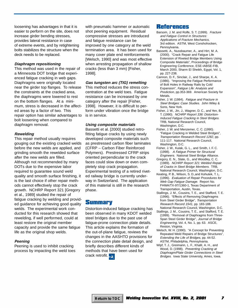
Hole drillingThe traditional repair method shown in Figure 4 consists of drilling a hole at the crack tip. The hole diameter issized to be at least 2ρ, where ρ isdetermined by Equation 1 [Barsomand Rolfe, 1999].
(1)
∆Κ is the stress intensity factor rangeand σy is the yield strength of thespecified steel. This repair is especiallyeffective when arresting crack propagation in low stress regions.However, cracking may recur if thehole size is not large enough or thestress range at the crack locationincreases. If this is the case, a
Stop Holes
Top Flange
Connection Plate
Figure 4. Repair by drilling stop holesat the crack tips.
Stiffeners and connection plates
are different conceptsin terms of their
structural purposes
ksi)in (for 4 yy
K σσρ
<∆

Welding Innovation Vol. XVIII, No. 2, 2001 5
supplemental step can be taken eitherby cold working the hole or by fillingthe hole with a pretensioned highstrength bolt, as will be described inthe sections to follow, so that the crackfront is restrained from further propa-gation. Hole drilling is easy to performand should be used wherever possibleeven when other repairs are alsoemployed at the same time.
Cold expansionCold expansion is an approach mostlyused in aircraft and railway rails forfatigue life enhancement of rivet orbolt holes. It is often performed bypulling a tapered mandrel, such as isused in the split sleeve process[Cannon et al., 1986], through oneside of the hole to the other, in orderto expand the hole diameter and to
produce plastic deformation in theperiphery. A zone of residual com-pressive stresses, both radially andcircumferentially, is then formed, sothat the initial fatigue resistance of thearea surrounding the hole can begreatly improved. However, thismethod has not been seen in use forcrack repair by any bridges. The stopholes in bridge repairs are oftendrilled, intercepting the fatigue cracksat the very ends. Cold expansion,therefore, would not be effectiveunless the holes were placed a certaindistance away from the crack tips toprovide room for the formation of thecompressive stress field. In addition,the crack locations, which often format plate-to-plate connection fillet welds,make it almost impossible to accom-modate tools (such as a sleeve) need-ed for cold expanding. This methodstill can be used in bridge fatigue
cracking repair if the cracks haveextended to a free surface away frommember intersections and the repairholes are drilled at a small distanceaway from the crack ends. But in mostcases, installing pretensioned bolts isa more cost-effective and widely usedmethod of strengthening the repairholes.
Filling drilled holes with pretensioned boltsPreloaded high-strength bolts areoften used to prevent crack reinitiationfrom the drilled holes. This methodforms local compressive stresses per-pendicular to the member surfacearound the hole, creates frictionbetween the faying surfaces, andeffectively keeps the crack from recur-ring. It has been used very often forthe repair of out-of-plane fatigue crack-ing in the web gap region, in additionto the hole drilling approach.
Stiffening the web gapHole drilling alone can only stop thegrowth of existing cracks, not the for-mation of new cracks. Some othermeasures have to be taken to makethe floor-beam (or diaphragm, cross-frame) to girder connection either
more rigid or more flexible, so that notonly are the existing cracks arrested,but also that no more cracks develop.If stiffening the web gap is desired,then either a welded or a bolted con-nection plate detail (Figures 5 and 6,respectively) may be used. The weld-ed detail is the simplest, but it can onlyresist stress ranges up to AASHTOfatigue detail Category C. Weld qualityis a concern if an overhead position isrequired. A bolted detail repair canimprove the fatigue resistance to detailCategory B. As shown in Figures 6(a)and 6(b), either an angle or a T-sectioncan be used to bolt the connectionplate to the girder flange. However, ifthe repair is performed at the topflange, part of the deck slab has to beremoved for bolt installation.
Girder Web Connection Plate
Bolted Repair Angle
Connection PlateGirder Web
Bolted Repair Tee
(a)
(b)
Figure 6. Stiffening web gap by bolting connection plate to girder flange.
Figure 5. Stiffening web gap by weld-ing connection plate to girder flange.
To release the constraints at the
cracked area, the diaphragms
were lowered to reston the bottom flanges
Repair Welds

6 Welding Innovation Vol. XVIII, No. 2, 2001
Bolted splicesIf large fatigue cracks have developeddeep into the girder web, the load-carrying capacity of the main structuralmember is impaired, which may affectthe structural integrity of the bridge.This is especially of concern when thecracks are located in a tension zone.As shown in Figure 7, the repair canbe performed by removing the originalconnection plates and bolting reinforc-ing splices (or coverplates) on bothsides of the web. New connection
plates also need to be connectedrigidly to girder flanges, either by weld-ing or bolting. Thus the cracked webis stiffened and the girder sectionproperties are restored by this retrofit.
Cutting the connection plate backThis method was used in 1980 for theretrofit of Des Moines Bridge [Fisher,1984]. It has since been used by IowaDOT on about 50 two-girder bridgesexperiencing small web gap cracks.None of them have yet experiencedcracking problems after the repair.Bridges in other states, such as theLexington Avenue Bridge (Minnesota),
the Poplar Street Bridge (Illinois), andthe Midland County Bridge (Texas)[Keating et al., 1996], were alsorepaired by employing this approach atthe web gap locations. As illustratedin Figure 8, part of the connectionplate is cut back so that the area ofthe girder web below the flange is suf-ficiently flexible to accommodate theout-of-plane rotation. Both field andlaboratory tests showed that the sec-ondary stress is significantly reducedafter the connection is softened. Thecut surface should be well finished toprevent crack reinitiation. To efficientlyrelease the restrained web, a minimumcut-short dimension of 12 in. (300 mm)is recommended for the connectionplate [Fisher et al., 1990].
Diaphragm removalDiaphragms and cross-frames areimportant during construction becausethey provide lateral bracing to the gird-ers and stabilize the entire structuralsystem. Once the deck slab is placed,
they are no longer needed if construc-tion stability is their only function.Removing interior diaphragms cancompletely eliminate the secondarystresses that cause fatigue cracks inthe girder web, but it can also increasethe in-plane bending stresses in themain girders. Stallings et al. [1996 &1998] performed field testing of bothcompletely and partially removingdiaphragms of two Alabama DOTbridges. The findings indicated that a15% increase in girder stress can rea-sonably be expected after the repair.Thus it is recommended that repair ofout-of-plane fatigue by diaphragmremoval only be considered for bridgeswith rating factors exceeding 1.15.
This repair method should be usedwith caution since it would increasethe girder stresses and decrease thestructural resistance against unexpect-ed loading conditions such as earth-quake or vehicle collisions. Careshould also be taken to make surethat any subsequent removal of theconcrete slab considers girder stability.
Bolt looseningWipf et al. [1998] investigated the effectof repair by loosening the cross-frame-to-connection-plate bolts on five IowaDOT bridges. Field measurement indicated that the maximum web gapstress ranges at the tested locationswere reduced by 25–85%, the maximum out-of-plane distortion wasreduced by 20–88%, and the maximumforces in the diaphragm diagonals werereduced by 73–95%. Compared withthe diaphragm removal method, bolt
Rewelding, if well performed, could at least restore
the original membercapacity
Figure 7. Repair of girder web by using splice plates.
Figure 8. Repair by cutting connection plate back.
Plate
Holes
Connection
Cut-short
≥ 12 in.
Floor-beam
RetrofittingGirder Web
Stop Hole
LFlange Splice P
" Ø A325
Web Splice P
78
L
Bolt (Typ.)
8
Bolt (Typ.)
" Ø A3257
New Conn. P
Web Splice P
(Both Sides)L
L
165
Flange Splice PL
165
Welding Innovation Vol. XVIII, No. 2, 2001 7
loosening has advantages in that it iseasier to perform on the site, does notincrease girder bending stresses, provides lateral resistance in case of extreme events, and by retighteningbolts stabilizes the structure when thedeck needs to be replaced.
Diaphragm repositioningThis method was used in the repair ofa Minnesota DOT bridge that experi-enced fatigue cracking in web gaps.Diaphragms were originally locatednear the girder top flanges. To releasethe constraints at the cracked area,the diaphragms were lowered to reston the bottom flanges. At a mini-mum, stress is decreased in the affect-ed areas by a factor of two. Thisrepair option has similar advantages tobolt loosening when compared todiaphragm removal.
ReweldingThis repair method usually requiresgouging out the existing cracked weldsbefore the new welds are applied, andgrinding smooth the rewelded surfaceafter the new welds are filled.Although not recommended by manyDOTs due to the expensive laborrequired to guarantee sound weldquality and smooth surface finishing, itis the last choice if other repair meth-ods cannot effectively stop the crackgrowth. NCHRP Report 321 [Gregoryet al., 1989] studied the repair offatigue cracking by welding and provid-ed guidance for achieving good qualitywelds. The experimental work con-ducted for this research showed thatrewelding, if well performed, could atleast restore the original membercapacity and provide the same fatiguelife as the original shop welds.
PeeningPeening is used to inhibit crackingprocess by impacting the weld toes
with pneumatic hammer or automaticshot peening equipment. Residualcompressive stresses are introducedand fatigue resistance can beimproved by one category at the weldtermination area. It has been used formany cover plate end reinforcements[Welsch, 1990] and was most effectivewhen arresting propagation of shallowcracks (less than 3 mm) [Fisher,1998].
Gas tungsten arc (TIG) remeltingThis method reduces the stress con-centration at the weld toes. Fatigueresistance can be increased by onecategory after the repair [Fisher,1998]. However, it is difficult to per-form under vibration once the bridge is in service.
Using composite materialsBassetti et al. [2000] studied retro-fitting fatigue cracks by using newlydeveloped composite materials suchas prestressed carbon fiber laminates(CFRP – Carbon Fiber ReinforcedPolymers). Prestressed CFRP stripsoriented perpendicular to the crackfaces could slow down or even com-pletely stop crack propagation.Experimental testing of a retired rivet-ed railway bridge is currently under-way in Switzerland. The application of this material is still in the researchphase.
SummaryDistortion-induced fatigue cracking hasbeen observed in many KDOT weldedsteel bridges due to the past use offatigue-prone connection plate details.This article explains the formation ofthe out-of-plane fatigue, reviews thechanges in the AASHTO provisions forthe connection plate detail design, andbriefly describes different kinds ofmethods that have been used forcrack retrofit.
ReferencesBarsom, J. M. and Rolfe, S. T. (1999). Fracture
and Fatigue Control in Structures:Applications of Fracture Mechanics, 3rd edition. ASTM, West Conshohocken,Pennsylvania.
Bassetti, A., Nussbaumer, A., and Hirt, M. A.(2000). “Crack Repair and Fatigue LifeExtension of Riveted Bridge Members UsingComposite Materials”, Proceedings of BridgeEngineering Conference, ESE-IABSE-FIB,March 2000, Sharm El Sheikh, Egypt, Vol. 1,pp. 227-238.
Cannon, D. F., Sinclair, J., and Sharpe, K. A.(1986). “Improving the Fatigue Performanceof Bolt Holes in Railway Rails by ColdExpansion”, Fatigue Life: Analysis andPrediction, pp.353-369. American Society forMetals.
Fisher, J. W. (1984). Fatigue and Fracture inSteel Bridges: Case Studies. John Wiley &Sons, New York.
Fisher, J. W., Jin, J., Wagner, D. C., and Yen, B.T. (1990). NCHRP Report 336: Distortion-Induced Fatigue Cracking in Steel Bridges.TRB, National Research Council,Washington, D.C.
Fisher, J. W. and Menzemer, C. C. (1990).“Fatigue Cracking in Welded Steel Bridges”,Transportation Research Record 1282, pp.111-117. National Research Council,Washington, D.C.
Fisher, J. W., Kulak, G. L., and Smith, I. F. C.(1998). A Fatigue Primer for StructuralEngineers. National Steel Bridge Alliance.
Gregory, E. N., Slate, G., and Woodley, C. C.(1989). NCHRP Report 321: Welded Repairof Cracks in Steel Bridge Members. TRB,National Research Council, Washington, D.C.
Keating, P. B., Wilson, S. D.,and Kohutek, T. L.(1996). Evaluation of Repair Procedures forWeb Gap Fatigue Damage. Report No.FHWA/TX-97/1360-1, Texas Department ofTransportation, Austin, Texas.
Stallings, J. M., Cousins, T. E., and Stafford, T. E.(1996). “Effects of Removing Diaphragmsfrom Steel Girder Bridge”, TransportationResearch Record 1541, pp. 183-188.National Research Council, Washington, D.C.
Stallings, J. M., Cousins, T. E., and Stafford, T. E.(1999). “Removal of Diaphragms from Three-Span Steel Girder Bridge”, Journal of BridgeEngineering, Vol. 4, No. 1, pp. 63. ASCE,Reston, Virginia.
Welsch, W. H. (1990). “A Concept for PreventingRepeated Weld Repairs of Bridge Structures”,Extending the Life of Bridges, pp. 44-52.ASTM, Philadelphia, Pennsylvania.
Wipf, T. J., Greimann, L. F., Khalil, A. H., andWood, D. (1998). Preventing Cracking atDiaphragm/Plate Girder Connections in SteelBridges. Iowa State University, Ames, Iowa.

8 Welding Innovation Vol. XVIII, No. 2, 2001
The ProjectAt Butler Manufacturing, we receivedan order for a metal factory building tobe used for the manufacture of candy.The design of the roof beams posed aspecial challenge due to the possibilitythat factory dust might accumulate onthe top side of the bottom flanges overthe years, and then fall as a clump intoa batch of candy while it was being
made, ruining it (Figure 1). To elimi-nate this possibility, the design engi-neer had specified that the bottomflanges must be covered with sloping
covers. The original specificationrequired welding the full length of thesteeply sloped covers over the bottomflanges of the roof beams. Accordingto the design specifications, the covershad to be welded; they could not befastened using adhesive.
Fabrication ChallengesDue to the welding requirement and tosimplify the erection of the building, wedecided to weld the covers offsite in ourfabrication plant. The original designcalled for a simple 1/8 in. (3 mm) thickflat plate welded to the vertical web ofthe beam and to the horizontal bottomflange at the outer edge (Figure 2). Weattempted to weld samples to developthe welding procedure specification.These weld samples quickly revealedfour problems with the design:
1. It was very difficult to get the piecesto fit at the outside corner of theflange since the flange was rounded.
2. Due to the steep slope of the plate,it was difficult to find the weld jointat the edge of the flange, as it wasalmost a butt joint.
Persistence Pays Off
Lessons Learned in the FieldContributed by D. Robert Lawrence II, CWI, CWEButler Manufacturing CompanyGalesburg, Illinois
The heat would expand the coverfaster than either
the web or the flange
Figure 1. The design of the roof beams had to be such that this would not happen!
Editorial Note: Last year, Omer W.Blodgett initiated a new forum forWelding Innovation readers, “LessonsLearned in the Field.” Inviting readersto contribute their own accounts oflessons they learned on the job, ratherthan in the classroom, Mr. Blodgettcited the opportunity to “take our blind-ers off, expand our limited world view,and test our assumptions.” RobLawrence of Butler Manufacturing wasthe first to respond, with his submis-sion of this piece. The editors lookforward to hearing from more of youwho have similar “ah-ha!” experiencesto share.

Welding Innovation Vol. XVIII, No. 2, 2001 9
3. If the cover was welded to one sidefirst, the beam would sweep in thedirection of the welded side.
4. Attempts to weld the joint resulted inseparation of the cover plate fromthe web or flange due to the differ-ent thermal expansion rates for theweb, flange and cover.
The cover was 1/8 in. (3 mm) thick, theweb was ¼ in. (6 mm) thick, and theflange was ½ in. (13 mm) thick. Whenthis joint was being welded, the heatwould expand the cover faster thaneither the web or the flange. Aftersome length of welding, usually about8 in. (200 mm), the cover would bowaway from the tack welded joint. Morefrequent tacking was attempted, butthe expansion would break the tackwelds. Furthermore, the tack weldscaused visually unacceptable “lumps”in the welds. By using a back-step-ping weld sequence, we could get thewelding done, but the fastest travelspeed attainable by hand was about12 ipm (300 mm/min.) and the weldinghad to be performed in 8 in. (200 mm)increments. There were covers on allthe roof beams and mezzaninebeams. This was going to require an unacceptable amount of time.
Discussions with the design engineerresulted in the cover design beingchanged to a formed shape with a lapjoint to the web and a flare-vee joint to
the flange (Figure 3). These designchanges made it much easier to fit thecovers and provided better weld jointsboth to the web and to the flange. Theattachment to the web was now a“real” fillet weld, and the attachment tothe flange was a flare vee that made itmuch easier to see and follow the jointwhen welding.
There was still the problem of therequired back-stepping welding tech-nique that was very slow. Furtherexperimentation, using a side beamseam welder in an attempt to speedup the welding process and reducethe amount of time that was going tobe required in the fabrication shop,showed that if the weld travel speedwas increased to 20 ipm (500
mm/min.), the weld length that couldbe made before the cover separatedfrom the web or flange was longer.When I observed that, I suspected thatthe thermal expansion caused by the
welding was traveling through the thincover faster than the thicker web andflange and was causing the cover tolengthen, in turn causing the cover tobow away from the heavier web andflange due to the different rates ofthermal expansion (Figure 4). Furtherexperiments showed that still fastertravel speeds further increased thelength that could be welded before the cover bowed away.
Faster travel speedsfurther increased thelength that could bewelded before thecover bowed away
Figure 2. The original design posedsome problems.
Figure 3. The revised design made iteasier to fit the covers and providedbetter weld joint configurations.
Figure 4. During welding, different rates of thermal expansion caused the thinner material of the cover to bow away from the heavier web and flange.

10 Welding Innovation Vol. XVIII, No. 2, 2001
The Answer:Outrunning ThermalExpansionBy continuing to experiment, welearned that once the weld travelspeed exceeded the rate of heat trans-fer through the thinner cover, the coverdid not bow away from the beam at all.The travel speed, in this case, wasabout 45 ipm (1,100 mm/min.). Thistheoretically solved one problem, butat the same time created another. Ahand welder simply cannot operate at a travel speed of 45 ipm. The weldtravel speed that was required to elimi-nate the bowing problem was furthercomplicated by the 40-ft. (12-m) lengthof the beams. Plus, we still had thesweep problem.
To apply this knowledge about thetravel speed and to solve the otherproblems, we needed to mechanizethe process using two welding units,each running on opposite sides of thebeam in a mirrored configuration. Toaccomplish this, we purchased a Bug-O portable travel carriage, 40 ft.(12 m) of track, and two sets of torchholders. We mounted two weldingtorches on opposite sides of the travelcarriage using rack and pinionadjusters, and hung an opaque weld-ing curtain with an inserted weldingshade outside the welding torches sothe welder-operators wouldn’t have touse welding helmets (Figure 5).
The DC-600 welding machines wereconnected to remote pendant controlsfor each weld head that were wired toseparately start the weld, but collec-tively to stop the welding. That way ifeither welder had difficulty, he couldstop both welders at the same time.The travel carriage was set for a 45ipm (1,100 mm/min.) travel speed.
After production started, the supervisornoticed that it took too much time todisassemble the sections of track, movethem to the next beam, reassemble
them, then re-align the track with thebeam. To solve this problem, wemounted the entire Bug-O assembly on a light-weight fabricated rectangulartube with edge guides to align theentire system with the top flange of thebeam in a single move.
Using this set-up, we were able to safely make the welds in a timely fashion, with a good degree of operatorcomfort, without generating sweep inthe beams.
Figure 5. This set-up allowed the welding operators to weld faster than therate of thermal expansion.
Welding of Aluminum AlloysOctober 9–12, 2001 2.5 CEUsFee: $595
If you are already familiar with basic weldingprocesses, this course will sharpen your knowl-edge and skills with regard to aluminum alloymaterials, processes, equipment and techniques.Consisting of equal amounts of classroom andhands-on welding time, this four-day course isdesigned for engineers, technologists, weldingtechnicians and fabricators.
AND CONTINUED FROM PREVIOUS YEARS…For the design professional:
Fracture & Fatigue Control in StructuresOctober 16–18, 2001 2.0 CEUs $595
Blodgett’s Design of WeldmentsNovember 13–15, 2001 2.0 CEUs $595
PLUS, OTHER LINCOLN ELECTRIC TECHNICAL PROGRAMS
Basics for the Welding IndustryOctober 16–19, 2001 $249
Industrial Processes for the Welding IndustryOctober 23–26, 2001 $249
Lincoln Electric Professional Programs
Opportunities
Space for all programs is limited, so register early to avoid disappointment. For full details, visitour web site at www.lincolnelectric.com, call 216/383-2240, or write to Registrar, ProfessionalPrograms, The Lincoln Electric Company, 22801 Saint Clair Avenue, Cleveland, OH 44117-1199.

Welding Innovation Vol. XVIII, No. 2, 2001 11
Key Concepts in Welding EngineeringBy R. Scott Funderburk, P.E.
Selecting Filler Metals:Electrodes for Stress Relieved Applications
IntroductionThis is the third and final installment in a series on selecting filler metals.Many filler metals are classified in the“as-welded” condition. This simplymeans that no subsequent heat treat-ing operation was performed followingwelding and prior to mechanical test-ing. Other electrodes are classified inthe stress relieved condition. Thechoice of an appropriate electrodeshould be based on the actual condi-tion of the welded part; either as-weld-ed or stress relieved.
What Is Stress Relieving?Thermal stress relieving is a postweldheat treating operation to reduceresidual stresses. The weldment isheated to a temperature below thetransformation temperature, approxi-mately 1350°F (730°C) for ferritic
steels, and held at this temperature for a predetermined amount of time,followed by uniform cooling.1
Stress relieving is often used toreduce distortion and to control dimen-sional stability and tolerances. Forexample, presses require precisedimensional control and are typicallystress relieved after welding. Stressrelieving may also be performed toprevent stress corrosion cracking orother deleterious results of residualstresses.
Which Electrodes Are Stress Relieved?Table 1 contains the AWS filler metalspecifications where deposited weldmetal can be classified in the stressrelieved condition.
If the filler metal classification includesone of the suffixes listed in Table 2,then that product is classified in thestress relieved condition. For exam-ple, Lincoln Outershield 81B2-H(E81T1-B2) is classified with a post-weld heat treatment of 1275°F (675°C)for 1 hour. The B2 suffix alone isenough information to know that thedeposit is stress relieved. Notice thatin Table 2 the stress relieving time andtemperature vary for each suffix, andin some cases they vary between thedifferent filler metal specifications. Forspecific requirements, the filler metalspecifications should be reviewed.2
a) The PWHT hold time is generally one hour, exceptthe A5.29-98 Specification (FCAW) requires 2 hoursfor B6, B6L, B8 and B8L.
b) A5.23-97 requires 1150°F (620°C) for B1.
c) A5.28-96 requires 1150°F (620°C) for B2 and B2L.
d) A5.23 requires 1150°F (620°C) for B5.
Table 1. AWS Specifications with FillerMetal Classified in the Stress RelievedCondition*
Table 2. Stress Relieving ElectrodeSuffixesa
* The filler metal specifications use the term “Postweld Heat Treatment” rather than stress relieved.
Specification
A5.5 Low alloy SMAW
A5.23 Low alloy SAW
A5.28 Low alloy GMAW
A5.29 Low alloy FCAW
Application
AWSClassification
Suffix
A1 1150 (620)A2 1150 (620)A3 1150 (620)A4 1150 (620)
B1, B1L 1275 (690)b
B2, B2L, B2H 1275 (690)c
B3, B3L, B3H 1275 (690)B4, B4L 1275 (690)
B5 1275 (690)d
B6, B6L, B6H 1375 (740)B7, B7L 1375 (740)B8, B8L 1375 (740)
B9 1375 (740)C1, C1L 1125 (605)C2, C2L 1125 (605)
C5L 1075 (579)D1 1150 (620)D2 1150 (620)D3 1150 (620)Ni1 1150 (620)Ni2 1150 (620)Ni3 1150 (620)Ni4 1150 (620)Ni5 1150 (620)F1 1150 (620)F2 1150 (620)F3 1150 (620)
PWHTTemperature,
°F (°C)

12 Welding Innovation Vol. XVIII, No. 2, 2001
In the classification designation forsubmerged arc, the third characteridentifies the postweld heat treatmentcondition: either as-welded or stressrelieved. An “A” indicates as-welded
and a “P” designates postweld heattreatment. For example, an F7A4-EG-Ni1 flux/electrode combination is clas-sified in the as-welded condition, whilean F7P4-EG-Ni1 is classified in thestress relieved condition. In somecases, the same product can be clas-sified in both the as-welded and stressrelieved conditions (e.g., LincolnLA85/882 is classified as F7A4-EG-Ni1 and F7P4-EG-Ni1).
Potential ProblemsThree situations can arise where the“wrong” electrode is used.
• An electrode classified in the stressrelieved condition is used in anapplication that does not get stressrelieved.
• An electrode classified in the as-welded condition gets stressrelieved.
• The actual postweld heat treatmenttime and/or temperature differ fromthat of the classification.
If one of these scenarios occurs, itdoes not necessarily mean that is theresult will be a “bad” weld. However,the situation should be reviewed todetermine any influence on mechani-cal properties and quality.
Influence on strengthStress relieving typically reduces weldstrength by about 10 to 15%. Forexample, the tensile strength in the as-welded condition may be 80 ksi, whilein the stress relieved condition it mayonly be 70 ksi. Therefore, if an elec-
trode classified in the as-welded con-dition is stress relieved, the finaltensile strength could fall below theminimum classification tensilestrength. This situation would create aweld that is weaker than intended.
On the other hand, if a weld is madewith an electrode classified in thestress relieved condition and is notstress relieved after welding, then anovermatching strength relationshipmay exist. This situation is not neces-sarily detrimental. However, higherstrength welds generally lead to higherresidual stresses, lower ductility andgreater crack sensitivity. In addition,the AWS D1.1 Structural WeldingCode–Steel requires that the weldingprocedure be qualified by test if over-matching strength is used.
Influence on notch toughnessIn most cases, notch toughness isincreased by stress relieving. If an as-welded product is stress relieved,the notch toughness will most likely goup. However, if the product is classi-fied as stress relieved, and the CharpyV-Notch (CVN) properties are onlyslightly above the minimum values,this could be a problem if the welddeposit is not stress relieved. In thiscase, the as-welded CVN energy values could fall below the minimumrequirements. Furthermore, excessivelyhigh stress relieving temperatures canreduce the measured CVN toughnessvalues. Therefore, during stress reliev-ing care should be taken to control thetemperature and time at temperature.
ConclusionsIf stress relieving heat treatment is tobe conducted, the final weld propertiesand quality should be evaluated andthe filler metal should be one that isclassified in the stress relieved condi-tion. The influence of the heat treat-ment on the weld metal, heat-affectedzone and base metal propertiesshould be assessed. Finally, if theheat treatment time and temperatureare different than the filler metal classi-fication, then the possible effects ofthese differences should be evaluated.
1) R. Scott Funderburk. “Postweld HeatTreatment,” Welding Innovation, Vol XV, No. 2, 1998.
2) Copies of the filler metal specifications canbe ordered from AWS at http://www.aws.org
“as-welded” simply means that no subsequent heattreating operation was performed
Stress relieving typically reduces
weld strength by 10 to 15%

Welding Innovation Vol. XVIII, No. 2, 2001 13
Editor’s Note: Much of the content of this article was also included in apaper Prof. Zwiep delivered at theFourth International Conference onEngineering Education, held inSheffield, England, 17–20 April, 2000.
IntroductionSince 1948, The James F. Lincoln ArcWelding Foundation has providedmonetary awards to college engineer-ing students, at both the undergradu-ate and graduate levels, to encouragethe solution of design, engineering orfabrication problems. Students com-pete by submitting papers thatdescribe and illustrate their projects,which may relate to any type of build-ing, bridge or other structure, any typeof machine, products or mechanicalapparatus, or to arc welding research,testing, procedure or process develop-ment. Reports or projects preparedfor course work, including theses anddissertations, are eligible to be submit-ted as entries. Each student or teamof students must list on the entry formthe name of the professor or facultyadvisor who oversaw the work.
Solving design, engineering or fabrica-tion problems fully supports the out-comes Assessments associated with
the program criteria of theAccreditation Board for Engineeringand Technology (ABET), whichaccredits all engineering and technologycollege programs in the United States.
Scope of ProgramThe subject of the entries is design,and the topics covered are virtuallylimitless. For example, the range ofwinning titles in the 2000 competitionincluded:
Seatbelt HypertensionerDisposable Cassette System
for ATM CurrencySki Resort Parking
Structure DesignA Simple Anastomosis Device
for Coronary Artery Bypass Grafting
Voluntary Milking SystemBehavior of Square CFT
Beam-Columns with High StrengthConcrete Under Seismic Loading
Design and Fabrication of a Retractable Wheelchair Foot Tray
Improvement of Durability and Ergonomics for Packaging
In 2000, 35 projects won awards, andthere were 13 departmental honorari-ums. A total of 114 students wereinvolved in producing the winning pro-
jects (31 in the graduate division and83 in the undergraduate division).Students from the University of Illinois,Stanford University, and WorcesterPolytechnic Institute, colleges whichgive strong emphasis to project orient-ed education, have been consistentwinners of the Foundation’s awardsover the past decade.
Faculty Plays Key RoleThe success of the program is highlydependent on the faculty’s enthusiasm,encouragement, and mentoring of students. Professors are able to helpyoung people look beyond the class-room to envision real-world applica-tions for their design efforts. And justas in the work world, the program provides a cash incentive to studentsfor expending the effort required tosubmit entries of professional quality.
Studies of the success of students at Stanford University by ProfessorEmeritus Doug Wilde, and at theUniversity of Illinois by Professor JamesCarnahan, strongly commend theFoundation’s programs. The GeneralEngineering Department of theUniversity of Illinois publication “SeniorDesign Project, G.E. 242,” describesthe Foundation’s program as follows:
A Unique Mechanism for EnhancingEngineering EducationBy Donald N. Zwiep
Professor Emeritus, Worcester Polytechnic Institute and Chairman, James F. Lincoln Arc Welding Foundation
2002Engineering
Student
Design
Competition

14 Welding Innovation Vol. XVIII, No. 2, 2001
“ … the Lincoln awards are the nation’smost prestigious undergraduate engi-neering awards and represent theexcellence in engineering upon whichthe senior design project is based.”
JudgingMembers of the Jury of Awards areselected from various branches ofengineering, education, business,industry, or from any other suitablesource by the Chairman of theFoundation. Jury members receive an honorarium and reimbursement for their travel expenses.
Each entry is read independently byeach Juror, who receives only anunidentified original copy of the entry.If the Juror, through prior knowledge,is able to recognize any of theentrants, that Juror will not participatein any judging related to that particularentry. Jury activities take place over anominal two weeks of active review ofthe entries with a final meeting of allthe Jurors to select the winningentries. A distinctive feature of theJury process is the thoroughness ofthe review given each entry.
The Jurors use the following criteria toguide their decision-making process:
• Originality or Ingenuity• Feasibility• Results Achieved or Expected• Engineering Competence• Clarity of the Presentation
These criteria are entirely consistentwith the expectations for the outcomesassociated with the new accreditationmethodology being implemented in the United States. ABET’s EC2000accreditation process relies on engineering departments establishingexpected outcomes, measuring theaccomplishment of those outcomes,and correcting the curriculum to minimize the difference betweenexpectation and accomplishment.
The expected outcomes necessarilyinclude the “realization” process. Thismeans that students must succeed inspecifying, designing, building, andtesting a “product” appropriate to theirdiscipline. It is, of course, obvious thatsuch student design activities oftenprovide the basis for entries to theFoundation’s award programs. Whatmay not be as obvious is the feedbackthat such entries provide for continu-ous improvement of curricula. In thisway, the program’s Jurors, as con-stituents, provide valuable feedback toacademic programs.
The existence of patents in no wayaffects Jury ratings, nor does theFoundation have any financial interestin patent rights. The Jury’s decision isfinal in all cases. Any action of theJury may be certified by its Chairmanfor and on its behalf, and such certifi-cation shall be conclusive proof of allaction and proceedings.
PresentationThe Foundation encourages thepreparation of a professional qualitypaper based on a student’s regularcollege activities in courses and pro-jects as they are related to engineer-ing design. The entries normally meetmost or all of the ABET requirementsassociated with a capstone designactivity. The entries also demonstrate,contrary to an oft-heard criticism, thatengineering students are articulate intheir written expressions. Softwareprograms such as CAD, CAM, andFEM are commonly used. Drawings,photographs and similar illustrationsare encouraged.
The rules of the program stipulate thatidentifying marks such as the names ofstudents, faculty or their schools mustnot appear on the entries proper. Titlepages and entry data are removed fromeach entry prior to its review by mem-bers of the Jury of Awards in order toavoid any possibility of bias.
Rewards forParticipationFaculty and students find that just theprocess of preparing an entry providesintangible rewards of its own. Whenan entry actually wins, there is a cashprize (in 2001 the prizes ranged from$250 to $2000 each), the prestige ofrecognition, and the confirmation ofhaving developed and described aneffective solution to a challengingproblem.
The educational process that the students and faculty undertake as theywork on the entries enables young peo-ple to experience the stimulation of aprofessionally competitive atmosphere.The process constitutes an outstandingpreparation for the global challenges ofthe engineering profession.
Colleges note that having nationalaward winners affirms the excellenceof their academic programs, whiledeveloping and recognizing the pro-ject-advising capabilities of their facul-ty. Accrediting agencies, both nationaland regional, consider national awardwinning entries evidence of the qualityof engineering programs. Entries tothe Foundation’s college program areconsidered excellent examples of howto meet the engineering designrequirements of ABET.
ConclusionThe Engineering Student DesignCompetition, sponsored by The JamesF. Lincoln Arc Welding Foundation andnow in its 52nd year of operation, isrecognized as one of the most presti-gious engineering award programs inthe United States. The Foundation’sprograms are exclusively supported byThe Lincoln Electric Company ofCleveland, Ohio, and are presently limited by the organization’s Deed ofTrust to the United States. However,the Foundation is currently exploringavenues for expanding the global scopeof many of its activities, including, theaward programs.

Welding Innovation Vol. XVIII, No. 2, 2001 15
2002COLLEGE ENGINEERING AND TECHNOLOGY ENTRY FORM
ENTRY MUST BE POSTMARKED ON OR BEFORE MIDNIGHT, JUNE 15, 2002Secretary, The James F. Lincoln Arc Welding Foundation, P.O. Box 17188, Cleveland, Ohio 44117-0035
A PHOTOGRAPH MUST BE SUBMITTED OF EACH AUTHOR, WITH THE NAME WRITTEN ON THE BACK, WITH THE ENTRY.
Fill in information requested and attach to title page of paper being enteredin the Program. ENTRY MUST BE TYPED.
DO NOT PUT YOUR NAME OR NAME OF SCHOOL ANYWHERE INYOUR ENTRY OTHER THAN ON THE ENTRY FORM.
Subject or title of paper(put this title on Page 1 of paper also). _ _ _ _ _ _ _ _ _ _ _ _ _ _ _ _ _ _ _
_ _ _ _ _ _ _ _ _ _ _ _ _ _ _ _ _ _ _ _ _ _ _ _ _ _ _ _ _ _ _ _ _ _ _ _ _ _ _ _ _ _ _ _ _ _ _ _ _ _ _ _ _ _ _ _ _ _ _ _ _ _ _ _ _ _ _ _ _ _ _
_ _ _ _ _ _ _ _ _ _ _ _ _ _ _ _ _ _ _ _ _ _ _ _ _ _ _ _ _ _ _ _ _ _ _ _ _ _ _ _ _ _ _ _ _ _ _ _ _ _ _ _ _ _ _ _ _ _ _ _ _ _ _ _ _ _ _ _ _ _ _
To be entered in the following division (check only one):
!"Undergraduate Division !"Graduate Division
Department _ _ _ _ _ _ _ _ _ _ _ _ _ _ _ _ _ _ _ _ _ _ _ _ _ _ _ _ _ _ _ _ _ _ _ _ _ _ _ _ _ _ _ _ _ _ _ _ _ _ _ _ _ _ _ _ _ _ _ _ _ _ _ _ _ _ _ _ _ _ _ _ _ _ _ _ _
_ _ _ _ _ _ _ _ _ _ _ _ _ _ _ _ _ _ _ _ _ _ _ _ _ _ _ _ _ _ _ _ _ _ _ _ _ _ _ _ _ _ _ _ _ _ _ _ _ _ _ _ _ _ _ _ _ _ _ _ _ _ _ _ _ _ _ _ _ _ _ _ _ _ _ _ _ _ _ _ _ _ _ _ _ _ _ _ _ _ _ _ _ _ _ _ _ _ _ _ _ _ _ _ _ _ _ _
Professor or Faculty Advisor _ _ _ _ _ _ _ _ _ _ _ _ _ _ _ _ _ _ _ _ _ _ _ _ _ _ _ _ _ _ _ _ _ _ _ _ _ _ _ _ _ _ _ _ _ _ _ _ _ _ _ _ _ _ _ _ _ _ _ _ _ _ _ _ _ _ _ _ _ _ _ _
School Name _ _ _ _ _ _ _ _ _ _ _ _ _ _ _ _ _ _ _ _ _ _ _ _ _ _ _ _ _ _ _ _ _ _ _ _ _ _ _ _ _ _ _ _ _ _ _ _ _ _ _ _ _ _ _ _ _ _ _ _ _ _ _ _ _ _ _ _ _ _ _ _ _ _ _ _ _ _ _ _ _ _ _ _ _ _ _ _ _ _ _
School Address _ _ _ _ _ _ _ _ _ _ _ _ _ _ _ _ _ _ _ _ _ _ _ _ _ _ _ _ _ _ _ _ _ _ _ _ _ _ _ _ _ _ _ _ _ _ _ _ _ _ _ _ _ _ _ _ _ _ _ _ _ _ _ _ _ _ _ _ _ _ _ _ _
_ _ _ _ _ _ _ _ _ _ _ _ _ _ _ _ _ _ _ _ _ _ _ _ _ _ _ _ _ _ _ _ _ _ _ _ _ _ _ _ _ _ _ _ _ _ _ _ _ _ _ _ _ _ _ _ _ _ _ _ _ _ _ _ _ _ _ _ _ _ _ _ _ _ _ _ _ _ _ _ _ _ _ _ _ _ _ _ _ _
This paper completed by the undersigned author(s) within the period of June 16, 2001
to June 14, 2002.
Entrant(s) signature(s) _ _ _ _ _ _ _ _ _ _ _ _ _ _ _ _ _ _ _ _ _ _ _ _ _ _ _ _ _ _ _ _ _ _ _ _ _ _ _ _ _ _ _ _ _ _ _ _ _ _ _ _ _ _ _ _ _ _ _ _ _ _ _ _ _ _
_ _ _ _ _ _ _ _ _ _ _ _ _ _ _ _ _ _ _ _ _ _ _ _ _ _ _ _ _ _ _ _ _ _ _ _ _ _ _ _ _ _ _ _ _ _ _ _ _ _ _ _ _ _ _ _ _ _ _ _ _ _ _ _ _ _ _ _ _ _ _ _ _ _ _ _ _ _ _ _ _ _ _ _ _ _ _ _ _ _
_ _ _ _ _ _ _ _ _ _ _ _ _ _ _ _ _ _ _ _ _ _ _ _ _ _ _ _ _ _ _ _ _ _ _ _ _ _ _ _ _ _ _ _ _ _ _ _ _ _ _ _ _ _ _ _ _ _ _ _ _ _ _ _ _ _ _ _ _ _ _ _ _ _ _ _ _ _ _ _ _ _ _ _ _ _ _ _ _ _ _ _ _ _ _ _ _ _ _ _ _ _ _ _ _ _ _ _
NOTE: In case of joint authorship of an award winning Entry, each author will receivea check dividing the total award amount equally unless otherwise indicated. Pleasecheck one of the boxes below.!"Divide Equally !"Divide as follows:
_ _ _ _ _ _ _ _ _ _ _ _ _ _ _ _ _ _ _ _ _ _ _ _ _ _ _ _ _ _ _ _ _ _ _ _ _ _ _ _ _ _ _ _ _ _ _ _ _ _ _ _ _ _ _ _ _ _ _ _ _ _ _ _ _ _ _ _ _ _ _ _ _ _ _ _ _ _ _ _ _ _ _ _ _ _ _ _ _ _ _ _ _ _ _ _ _ _ _ _ _ _ _ _ _ _ _ _
_ _ _ _ _ _ _ _ _ _ _ _ _ _ _ _ _ _ _ _ _ _ _ _ _ _ _ _ _ _ _ _ _ _ _ _ _ _ _ _ _ _ _ _ _ _ _ _ _ _ _ _ _ _ _ _ _ _ _ _ _ _ _ _ _ _ _ _ _ _ _ _ _ _ _ _ _ _ _ _ _ _ _ _ _ _ _ _ _ _
STATEMENT OF CERTIFICATION(Must be signed by faculty member)
Following statement must be signed by a professor, instructor or the faculty advisor.
The author(s) of this paper _ _ _ _ _ _ _ _ _ _ _ _ _ _ _ _ _ _ _ _ _ _ _ _ _ _ _ _ _ _ _ _ _ _ _ _ _ _ _ _ _ _ _ _ _ _ _ _ _ _ _ _ _ _ _ _ _ _ _ _ _ _ _ _ _ _ _ _ _ _ _ _ _ _
(is/are) (was/were) registered at (school) _ _ _ _ _ _ _ _ _ _ _ _ _ _ _ _ _ _ _ _ _ _ _ _ _ _ _ _ _ _ _ _ _ _ _ _ _ _ _ _ _ _ _ _ _ _ _ _ _ _ _ _ _ _ _ _
and to the best of my knowledge this paper was originated and prepared by thestudent(s) named on this Entry Form.Signed _ _ _ _ _ _ _ _ _ _ _ _ _ _ _ _ _ _ _ _ _ _ _ _ _ _ _ _ _ _ _ _ _ _ _ _ _ _ _ _ _ _ _ _ _ _ _ _ _ _ _ _ _ _ _ _ _ _ _ _ _ _ _ _ _ _ _ _ _ _ _ _ _ _ _ _ _ _ _ _ _ _ _ _ _ _ _ _ _ _ _ _ _ _ _ _ _ _ _
_ _ _ _ _ _ _ _ _ _ _ _ _ _ _ _ _ _ _ _ _ _ _ _ _ _ _ _ _ _ _ _ _ _ _ _ _ _ _ _ _ _ _ _ _ _ _ _ _ _ _ _ _ _ _ _ _ _ _ _ _ _ _ _ _ _ _ _ _ _ _ _ _ _ _ _ _ _ _ _ _ _ _ _ _ _ _ _ _ _
Phone _ _ _ _ _ _ _ _ _ _ _ _ _ _ _ _ _ _ _ _ _ _ _ _ _ _ _ _ _ _ _ _ _ _ _ _ _ _ _ _ _ _ _ _ _ _ _ _ _ _ _ _ _ _ _ _ _ _ _ _ _ _ _ _ _ _ _ _ _ _ _ _ _ _ _ _ _ _ _ _ _ _ _
Name(s)
Professor or Faculty Advisor (Print Name Below)
AUTHOR(S) Please Type — No Abbreviations
CHECK WILL BE SENT TO HOME ADDRESS. NOTIFICATION 10/2002.Home address must be address at which you will receive mail October 2002.
Full Name
Soc. Sec. No. Home Phone
Home Address
City, State, Zip
School
School Address
City, State, Zip
Full Name
Soc. Sec. No. Home Phone
Home Address
City, State, Zip
School
School Address
City, State, Zip
Full Name
Soc. Sec. No. Home Phone
Home Address
City, State, Zip
School
School Address
City, State, Zip
Full Name
Soc. Sec. No. Home Phone
Home Address
City, State, Zip
School
School Address
City, State, Zip
Full Name
Soc. Sec. No. Home Phone
Home Address
City, State, Zip
School
School Address
City, State, Zip
Entries may not be submitted by more than five students.
Application and Rules can be found at www.lincolnelectric.com
The James F. LincolnArc Welding Foundation

16 Welding Innovation Vol. XVIII, No. 2, 2001
Mixing Welds and Bolts, Part 1Practical Ideas for the Design Professional by Duane K. Miller, Sc.D., P.E.
Design File
IntroductionThere are a variety of circumstances in which the engineermay need to assess the strength of a connection that iscomposed of both welds and mechanical fasteners. Today,mechanical fasteners are typically bolts, but older structuresmay include rivets. Such situations may be encounteredduring the course of rehabilitation, repair or strengtheningprojects. For new construction, bolts and welds may becombined in connections where the materials being joinedare initially secured with bolts, and then welded to gain thefull connection strength. As will be seen, calculating the totalcapacity of the connection is not as simple as totaling thearithmetical sum of the individual components (welds, bolts,and rivets). Such an assumption is unconservative, and theconsequences could be disastrous.
Part 1 of this two-part edition of “Design File” will deal withsnug-tightened and pretensioned mechanical fastenerscombined with welds. Part 2 will address combining weldswith slip-critical, high-strength bolted connections.
Some Background on Bolted ConnectionsBolted joints are described in the AISC Specification forStructural Joints Using ASTM A325 or A490 Bolts (June23, 2000) as either snug-tightened, pretensioned, or slip-critical (p. 23). A snug-tightened joint has the condition of“tightness that is attained with a few impacts of an impactwrench or the full effort of an ironworker using an ordinaryspud wrench to bring the plies into firm contact.”(p. xi). Apretensioned joint is one in which the bolts have beeninstalled in a manner so that the bolts are under significanttensile load with the plates under compressive load (p. x).Four acceptable methods are listed in Section 8.2: turn-of-
nut, calibrated wrench, twist-off-type tension-control bolts,and direct-tension-indicators. Slip-critical joints have boltsinstalled just as they would be in a pretensioned joint, butalso have “faying surfaces that have been prepared to pro-vide a calculable resistance against slip.” (p. xi).
In simple terms, in snug-tightened joints and pretensionedjoints, the bolts act as pins. Slip-critical joints work by fric-tion: the pretension forces create clamping forces and thefriction between the faying surfaces work together to resistslippage of the joint.
ASTM A325 bolts have a minimum tensile strength of 105–120ksi (725–830 MPa) depending upon the bolt diameter, whileA490 bolts must fall between 150 and 170 ksi (1035–1175MPa) tensile strength. Riveted joints behave more like snug-tightened joints, but the “pins” in this case are the rivets, andare typically about half the strength of A325 bolts.
When a mechanically fastened joint is loaded in shear, oneof two types of behavior is possible. The joint may havethe bolts or rivets bear against the sides of the holes in theconnected material, concurrently putting the bolt or rivetinto shear. The second possible behavior is that friction,introduced by the clamping forces provided by the preten-sioned fastener, resists the shear loading. No slippage isexpected in this joint, but the possibility exists nonetheless.
Snug-tight joints are acceptable for many applicationssince minor slippage may not adversely affect the perfor-mance of the connection. When there is significant loadreversal, pretensioned joints may be required. When jointsare subject to fatigue loads with reversal of direction, slip-critical joints are required.

Welding Innovation Vol. XVIII, No. 2, 2001 17
Figure 1.
Thus, an existing bolted connection may have beendesigned and built to any of these criteria. Riveted jointswould be considered the snug-tight type.
Adding Welds to Mechanically Fastened JointsWhile a weld may be composed of metal that is capable ofdemonstrating an elongation of 20% or more in an all-weld-metal tensile specimen, the same metal in a restrainedjoint may be incapable of delivering any significant defor-mation prior to fracture, due to the interaction of triaxialstresses. In other words, welded connections are rigid.Welded connections are stiff. Unlike snug-tightened boltedjoints that may slip as they are loaded, welds are notexpected to stretch and distribute the applied load to anygreat extent. In most cases, welds and bearing-typemechanical fasteners will not deform equally. The load istransferred through the stiffer part, and therefore the weldwill carry virtually all the load, sharing little with the bolts.And that’s why caution needs to be taken when welds andbolts and rivets are combined.
Code ProvisionsThe issue of mixing mechanical fasteners and welds isaddressed in the AWS D1.1:2000 Structural WeldingCode—Steel. Provision 2.6.3 states:
“Welds with Rivets or Bolts. Rivets or bolts used inbearing type connections shall not be considered assharing the load in combination with welds. Welds, if
used, shall be provided to carry the entire load in theconnection. However, connections that are welded toone member and riveted or bolted to the other memberare permitted. High-strength bolts properly installed asa slip-critical-type connection prior to welding may beconsidered as sharing the stress with the welds.”
The first three sentences of this provision address thetopic discussed here. The fourth sentence will beaddressed in part 2.
When the mechanical fasteners are of the bearing type anda weld is added, the capacity of the bolt is essentiallyignored. The weld must be designed to transfer all the load,according to this provision. This is, in essence, the same asthe requirement of AISC LRFD-1999, provision J1.9.However, the Canadian standard CAN/CSA-S16.1-M94 alsopermits the use of the capacity of the mechanical fastener orthe bolts alone when this is higher than the capacity of thewelds. All three standards are in agreement on this issue:the capacities of the bearing-type mechanical fasteners andthe welds cannot be added together.
AWS D1.1, paragraph 2.6.3, goes on to discuss an accept-able situation in the third sentence. Bolts and welds canbe combined in the situation where a connection consistsof two separate components, as illustrated in Figure 1. Onthe left is a welded connection, and on the right, a boltedone. This is acceptable. Each part of the overall connec-tion behaves independently, and thus, the Code providesan exception to the principles as contained in the first partof 2.6.3.

18 Welding Innovation Vol. XVIII, No. 2, 2001
The previous provisions are applicable for new construc-tion. For existing structures, D1.1 paragraph 8.3.7, goeson to say:
“Use of Existing Fasteners. When design calculationsshow rivets or bolts will be overstressed by the newtotal load, only existing dead load shall be assigned tothem. If rivets or bolts are overstressed by dead loadalone or are subject to cyclic loading, then sufficientbase metal and welding shall be added to support thetotal load.”
The first sentence permits sharing of loads betweenmechanical fasteners and welds if the structure is pre-loaded (i.e., any slip has already occurred), but only thedead load can be assigned to the mechanical fastener.Welds must be used to take up all the applied or live load.No such sharing of loads is permitted when the mechanicalfasteners are already overloaded. When cyclic loading isinvolved, no load sharing is permitted.
An IllustrationConsider a lap joint originally connected with snug-tightbolts, as shown in Figure 2a. Additional capacity is beingadded to the structure, and the connection and theattached members must be increased to provide twice asmuch strength. Figure 2b illustrates the basic plan tostrengthen the members. What should be done to theconnection?
Since the new steel is going to be joined to the old with fil-let welds, the engineer decides to add some fillet welds tothe connection. Since the bolts are still in place, the initialthought is to add only the welds required to transfer theadditional capacity of the new steel, expecting 50% of theload to go through the bolts, and 50% through the newwelds. Will this be acceptable?
Let’s first assume there is no dead load currently applied tothe connection. In this case, D1.1 paragraph 2.6.3 applies.In this bearing type connection, the welds and bolts cannotbe “considered as sharing the load.” Thus, the specifiedweld size must be large enough to carry the entire deadand live load. The capacity of the bolts cannot be consid-ered in this example.
Next, let’s assume a dead load is applied. Further, let’sassume that the existing connection is adequate to transferthe existing dead load. D1.1 paragraph 8.3.7 applies in thiscase and the new welds are only required to carry theincreased dead load and the total live load. The existing dead load can be assigned to the existing mechanical fasteners.
Figure 2a.
Figure 2b.
ConclusionIn summary, the answer to the question “Is this accept-able?” depends on the loading conditions. In the first casewhere no dead load was assumed, the answer is “no.”Under the specific conditions of the second scenario, theanswer is “yes.” It cannot be concluded that the answer willalways be “yes” simply because dead load is applied. Thelevel of dead load, the adequacy of the existing mechanicalconnection, and the nature of final loading (whether staticor cyclic) could change the answer.
All of the above apply to mechanical fasteners of the pintype. Part 2 will deal with high strength, slip-critical boltedconnections in combination with welds. The technicalaspects of the content of part 2 are currently being evaluat-ed by technical committees. The work of the committeesmay not be complete in time for the next issue of WeldingInnovation. Part 2 will be forthcoming just as soon as allthe technical information is available.

Welding Innovation Vol. XVIII, No. 2, 2001 19
IntroductionSafeco Field, the new home of theSeattle Mariners baseball team, features a unique retractable roof.Modern arc welding enabled the designand construction of the stadium’sspectacular tri-chord roof trusses,which contribute both structurally andaesthetically to the stadium. Arc welding was also used for other criticalelements throughout the stadium, andturned out to be the only suitablemethod to meet the demanding construction schedule.
Project DescriptionThe retractable roof spans 655 ft.(200 m) over the stadium, providingthe ballpark with a giant umbrella(Figure 1) to prevent the potential forrained-out games in Seattle’s wet climate. In its retracted position(Figure 2), the roof is stored completelyoff the stadium, over the BurlingtonNational Railroad right-of-way adjacentto the ballpark.
The roof rides atop two 800-ft.-long(244 m) runway structures, standing100 ft. (30 m) tall on the south sideand 50 ft. (15 m) tall on the north sideof the stadium. The shorter runway onthe north side allows spectacularviews of Seattle and Puget Soundfrom the seating bowl.
The three independent roof panelscover 8.7 acres (3.5 hectares) andweigh approximately 12,000 tons(10,900 m tons). The largest, centerpanel is 275 ft. (84 m) above the playing field. The two lower panelsthat slide underneath the center panel
Tri-Chord Roof Trusses Enhance Safeco FieldBy Kurt A. Norquist
Skilling Ward Magnusson Barkshire, Inc.Seattle, Washington
Figure 2. Computer model of the Safeco Field roof in the retracted position.
Figure 1. Aerial view of computer model with the roof in the field position.
in the retracted position have down-turned trusses with a bottom chord165 ft. (50 m) above the field.
The use of the Burlington NorthernRailroad’s right-of-way and the lineartracking system for the roof allowedthe roof trusses to be assembled on a
stationary, temporary platform, locatedoutside the main stadium footprint.The large, stable tri-chord roof trusseswere assembled one at a time on topof the temporary staging platform, androlled off to the side, making way forthe erection of the next truss. Thisallowed the erection of the roof struc-

20 Welding Innovation Vol. XVIII, No. 2, 2001
ture to be done completely outside ofthe stadium bowl, taking it off the criti-cal path for the rest of the project.
One of the key design objectives wasto support the roof on moveable “legs.”This makes the roof unlike any otherretractable roof that has ever beenbuilt. When the roof retracts, the sup-porting walls move with it to truly makean open air ballpark—not just a build-ing with a sunroof.
The architect insisted that these legsbe as slender and elegant as possible,while also, of course, being resistantto all wind and earthquake forces. Theonly way to achieve this was to usewelded steel plate in the legs.
Maximizing Use of Shop WeldingThe roof structures had to bedesigned so that they could be quicklyerected in order to meet a veryaggressive construction schedule forthe ballpark. As designers, we werealso concerned about the use of fieldwelding on a structure that would beerected primarily during the wet, windypart of the year. Therefore, we decid-ed to make maximum use of shopwelding to minimize the amount ofwelding that would have to be doneoutdoors in the elements. Thisallowed us to take advantage of costeffective shop welding processes, aswell as the higher production rates andbetter quality control attainable in ashop environment. It also eliminatedthe time, expense and safety issuesattendant to having welders work inrelatively inaccessible areas, highabove the Burlington NorthernRailway’s right-of-way.
The use of modern welding and test-ing technology allowed us to designextremely complex roof truss and leg
connections, which were prefabricatedin a controlled shop environment. Thisreduced the amount of time and workrequired to assemble the trusses inthe field.
Curved Geometry of the TrussesOne of the key elements required toattain the overall curved geometry ofthe trusses was the ability to articulatethe truss chords at each work pointwhere the four diagonals attach to thechord. The most economical andpractical way to accomplish this wasby using full-penetration welds of thejumbo sections, ranging in size fromW14x145 to W14x730. Extra precau-tions were taken to ensure the integrityof the joints in these large sections(Figure 3). Welding electrodes wererequired to have a minimum specifiedCharpy V-Notch (CVN) rating of 20foot-pounds (27.2 joules) at minus20°F (-29°C). CVN tests were per-formed on the structural members toensure that the base metal also had
high toughness properties. All basematerials around the full-penetrationsplices had ultrasonic and magneticparticle tests before welding of thejoints to ensure that there were noflaws in the base metal that mightpropagate into the welds.
Based on an AISC advisory on thepotential for problems with rotary-straightened members yielding lowCVN numbers in the “k” zone, allmembers requiring full-penetration buttsplices were specified as gag straight-ened. All of the truss chord members
When the roof retracts,
the supporting wallsmove with it
were specified as A913 Grade 65material. Despite the manufacturer’sclaims of no required preheating forthis material, a minimum preheat ofCategory B was specified for allcritical welds.
Welding ProceduresMinimize Distortion It was critical that the fabricatorsmaintain the correct geometry, due tothe nature of the very large and com-plex weldments that are attached tothe truss chords. The fabricatorsdeveloped detailed welding proce-dures to minimize the distortion of theplates and chord elements during thewelding process. As a result of theirdiligent effort, the fit-up of the trussesin the field was outstanding (Figure 4),with a minimum number of field modi-fications required.
Welding PreventsCorrosionThe entire roof structure is exposed to the wet environment of the PacificNorthwest. The welding details weredeveloped with special considerationgiven to minimizing the potential corro-sion of the structural steel. Jointswere designed so that all surfacescould be prepainted before assembly.Field welding was minimized to preventpotential corrosion of heat-affectedareas where the paint would beburned off in the welding process.Where field welding was required,special details were provided to seal-weld inaccessible areas that could notbe painted after welding. Shop seal-welds (Figure 5) were used in manyapplications, such as large, round lidenclosures which were welded to thediagonal braces as they pass throughthe roof membrane. These lids act asa top to a round PVC enclosure that ispart of the roof membrane (Figure 6).

Welding Innovation Vol. XVIII, No. 2, 2001 21
Figure 3. Bottom chord assemblyat the splice location with weldeddiagonal connections.
Figure 4. Erection crew assembling truss.
Figure 5. Shop photo showingseal welds being placed aroundthe lid assemblies used forwaterproofing.
SummaryOn this project, welding was usedinstead of bolting wherever possiblebecause of its superior construction fit-up and corrosion resistance. Onlyarc welding provided the designers thelatitude to create such a complex andelegant structure, the first of its kind inthe world.
Figure 6. Lower chord of panel 3 withdiagonals and waterproof lid assemblies.

NON-PROFIT ORG.U.S. POSTAGE
PAIDJAMES F. LINCOLN
ARC WELDING FND.
Seattle’s Safeco Field features a unique retractable roof. See story on page 19.
P.O. Box 17188Cleveland, OH 44117-1199
TheJames F. LincolnArc WeldingFoundation


![Journal of American Science 0203arc welding, atomic hydrogen welding, shielded metal arc welding, plasma arc welding, electroslag welding, etc. Arc welding has been described [3] to](https://img.dokumen.tips/doc/110x75/5ec0a6e76045b75960496969/journal-of-american-science-arc-welding-atomic-hydrogen-welding-shielded-metal.jpg)