Embed Size (px)
Citation preview

Degree project inCommunication Systems
Second level, 30.0 HECStockholm, Sweden
D A O Y U A N L I
A Proxy for Distributed Hash Tablebased Machine-to-Machine Networks
K T H I n f o r m a t i o n a n d
C o m m u n i c a t i o n T e c h n o l o g y

Aalto UniversitySchool of ScienceDegree Programme in Security and Mobile Computing
Daoyuan Li
A Proxy for Distributed Hash Table basedMachine-to-Machine Networks
Master’s ThesisEspoo, June 29, 2011
Supervisors: Professor Gerald Q. Maguire Jr., Royal Institute of Technology (KTH)Professor Antti Ylä-Jääski, Aalto University
Instructor: Jani Hautakorpi, PhD, Ericsson Research NomadicLab, Finland
Aalto UniversitySchool of Science ABSTRACT OFDegree Programme of Security and Mobile Computing MASTER’S THESIS
Author: Daoyuan LiTitle:A Proxy for Distributed Hash Table based Machine-to-Machine Networks
Date: June 29, 2011 Pages: 14 + 74Professorship: Data Communications Software Code: T-110Supervisors: Professor Gerald Q. Maguire Jr.
Professor Antti Ylä-JääskiInstructor: Jani Hautakorpi, PhD
Wireless sensor networks (WSNs) have been an increasingly interest for bothresearchers and entrepreneurs. As WSN technologies gradually matured andmore and more use is reported, we find that most of current WSNs are stilldesigned only for specific purposes. For example, one WSN may be used togather information from a field and the collected data is not shared with otherparties.
We propose a distributed hash table (DHT) based machine-to-machine (M2M)system for connecting different WSNs together in order to fully utilize informa-tion collected from currently available WSNs. This thesis specifically looks athow to design and implement a proxy for such a system. We discuss why sucha proxy can be useful for DHT-based M2M systems, what the proxy shouldconsist of, and what kind of architecture is suitable. We also look into differentcommunication protocols that can be used in these systems and discuss whichones best suit our purposes. The design of the proxy focuses on network man-agement and service discovery of WSNs, and security considerations as well ascaching mechanisms in order to improve performance. A prototype is imple-mented based on our design and evaluated. We find it feasible to implementsuch a DHT-based M2M system and a proxy in the system can be necessaryand useful. Finally, we draw conclusions and discuss what future work remainsto be done.
Keywords: M2M, P2P, DHT, Proxy, Gateway, ZigBee, 6LoWPAN,CoAP, Cache
Language: English
i
Sammanfattning
Trådlösa sensornätverk (WSN) har en allt större intresse för både forskareoch företagare. Som WSN teknik successivt mognat och allt fler använderrapporteras, finner vi att de flesta av dagens WSN fortfarande är konstruer-ade enbart för särskilda ändamål. Till exempel kan en WSN användas föratt samla in information från ett fält och de insamlade data inte delas medandra parter.
Vi föreslår en distribuerad hashtabell (DHT) baserad maskin-till-maskin (M2M)system för att koppla olika WSN tillsammans för att fullt ut utnyttja informa-tion som samlats in från tillgängliga WSN. Denna avhandling tittar särskiltpå hur man kan utforma och genomföra en fullmakt för ett sådant system.Vi diskuterar varför en proxy kan vara användbart för DHT-baserade M2Msystem, vad proxy bör bestå av, och vilken typ av arkitektur är lämplig.
Vi tittar också på olika kommunikationsprotokoll som kan användas i dessasystem och diskuterar vilka som bäst passar våra syften. Utformningen avproxy fokuserar på nätverksadministration och service upptäckten av WSN,och med hänsyn till säkerheten samt cachning mekanismer för att förbättraprestanda. En prototyp genomfördes baserat på vår design och utvärderas.Vi tycker att det är möjligt att genomföra en sådan DHT-baserade M2Msystem och en proxy i systemet kan vara nödvändig och nyttig. Slutligendrar vi slutsatser och diskutera vad framtida arbete återstår att göra.
Nyckelord: M2M, P2P, DHT, Proxy, Gateway, ZigBee, 6LoWPAN, CoAP,Cache
ii

Acknowledgements
This thesis would not have been possible without the help of several individ-uals who in one way or another offered their valuable and generous assistancein the preparation and completion of this study.
First and foremost, I want to thank my supervisors, Professor Gerald Q.Maguire Jr. at Royal Institute of Technology and Professor Antti Ylä-Jääskiat Aalto University, for their guidance through this thesis project, especiallyProfessor Maguire, who has given me extremely helpful and concrete com-ments on my thesis drafts.
Secondly, I would like to express my gratitude to people at Ericsson ResearchNomadicLab. My industrial advisor Dr. Jani Hautakorpi has given me valu-able instructions in the design and implementation of the system, as well asin thesis writing. Section manager of LMF/TRM, Jouni Mäenpää warmlywelcomed me to the lab and generously offered his help during my stay inthe lab. My colleagues have offered many useful suggestions regarding thethesis. I have had very interesting discussions with Jaime Jiménez Bolonioand Nalin Gupta; those discussions have been of great help for my thesis.Rasib Hassan Khan and Gaëtan Charmette have been nice companies, es-pecially during lunch times when we talk and share stories and anecdotes.Their cheerful spirit has kept me motivated and enthusiastic.
Last but not least, I would like to thank my parents, whose kindness, dili-gence, and positive attitude towards life have deeply influenced me and havebeen an invaluable influence throughout my life.
Jorvas, Kirkkonummi, FinlandJune 22, 2011
Daoyuan Li
iii
Contents
Abstract i
Sammanfattning ii
Acknowledgements iii
Table of Contents iv
List of Tables viii
List of Figures ix
Abbreviations and Acronyms xi
1 Introduction 1
1.1 Overview . . . . . . . . . . . . . . . . . . . . . . . . . . . . . . 1
1.2 Problem Description . . . . . . . . . . . . . . . . . . . . . . . 2
1.3 Contributions . . . . . . . . . . . . . . . . . . . . . . . . . . . 2
1.4 Thesis Organization . . . . . . . . . . . . . . . . . . . . . . . . 3
2 Background 4
2.1 The Internet of Things . . . . . . . . . . . . . . . . . . . . . . 4
2.2 Machine-to-Machine Commmunication . . . . . . . . . . . . . 6
2.3 Wireless Sensor Networks . . . . . . . . . . . . . . . . . . . . 7
2.3.1 WSN Architecture . . . . . . . . . . . . . . . . . . . . 7
iv

2.3.2 WSN Sensor Node Architecture . . . . . . . . . . . . . 8
2.3.3 Routing in WSNs . . . . . . . . . . . . . . . . . . . . . 9
2.4 Protocols for Wireless Sensor Networks . . . . . . . . . . . . . 10
2.4.1 IEEE 802.15 Working Group . . . . . . . . . . . . . . . 10
2.4.2 IEEE Std 802.15.4TM . . . . . . . . . . . . . . . . . . . 11
2.4.3 ZigBeeTM . . . . . . . . . . . . . . . . . . . . . . . . . 12
2.4.4 6LoWPAN . . . . . . . . . . . . . . . . . . . . . . . . . 14
2.4.5 CoAP . . . . . . . . . . . . . . . . . . . . . . . . . . . 14
2.5 Distributed Hash Tables . . . . . . . . . . . . . . . . . . . . . 15
2.5.1 Hash Algorithms . . . . . . . . . . . . . . . . . . . . . 16
2.5.2 Consistent Hashing . . . . . . . . . . . . . . . . . . . . 17
2.5.3 Chord . . . . . . . . . . . . . . . . . . . . . . . . . . . 18
2.6 Simple Network Management Protocol . . . . . . . . . . . . . 19
2.7 Summary . . . . . . . . . . . . . . . . . . . . . . . . . . . . . 20
3 Design 22
3.1 Motivation . . . . . . . . . . . . . . . . . . . . . . . . . . . . . 24
3.2 Objective . . . . . . . . . . . . . . . . . . . . . . . . . . . . . 25
3.3 Principles . . . . . . . . . . . . . . . . . . . . . . . . . . . . . 26
3.4 Architecture . . . . . . . . . . . . . . . . . . . . . . . . . . . . 27
3.5 Details . . . . . . . . . . . . . . . . . . . . . . . . . . . . . . . 28
3.5.1 Proxy Joining and Leaving . . . . . . . . . . . . . . . . 29
3.5.2 WPAN Management . . . . . . . . . . . . . . . . . . . 29
3.5.2.1 WPAN Start Up . . . . . . . . . . . . . . . . 30
3.5.2.2 Node Joining . . . . . . . . . . . . . . . . . . 30
3.5.2.3 Node Leaving . . . . . . . . . . . . . . . . . . 31
3.5.2.4 Naming, Addressing, and Routing . . . . . . . 34
3.5.3 WPAN Service Management . . . . . . . . . . . . . . . 34
3.5.3.1 Service Discovery . . . . . . . . . . . . . . . . 35
3.5.3.2 Service Updates . . . . . . . . . . . . . . . . . 36
v

3.5.4 Caching . . . . . . . . . . . . . . . . . . . . . . . . . . 36
3.5.4.1 Caching for WPAN Nodes . . . . . . . . . . . 37
3.5.4.2 Caching in DHT . . . . . . . . . . . . . . . . 37
3.5.5 Security . . . . . . . . . . . . . . . . . . . . . . . . . . 38
3.5.5.1 Secure Communication between WWAN Peers 38
3.5.5.2 WPAN Security . . . . . . . . . . . . . . . . . 38
3.6 Summary . . . . . . . . . . . . . . . . . . . . . . . . . . . . . 39
4 Implementation 40
4.1 Hardware and Software . . . . . . . . . . . . . . . . . . . . . . 40
4.1.1 WPAN Nodes . . . . . . . . . . . . . . . . . . . . . . . 40
4.1.2 Proxy and Wide Area Nodes . . . . . . . . . . . . . . . 42
4.1.3 Prototype Architecture . . . . . . . . . . . . . . . . . . 43
4.2 Proxy Start Up . . . . . . . . . . . . . . . . . . . . . . . . . . 43
4.3 WPAN Node Joining and Leaving . . . . . . . . . . . . . . . . 45
4.4 Application Logic . . . . . . . . . . . . . . . . . . . . . . . . . 45
4.4.1 CoAP Message Parsing . . . . . . . . . . . . . . . . . . 45
4.4.2 Waspmote Application Packet Fragmentation and Re-assembling . . . . . . . . . . . . . . . . . . . . . . . . . 46
5 Discussions 47
5.1 Functionality Evaluation . . . . . . . . . . . . . . . . . . . . . 47
5.2 Performance Measurements . . . . . . . . . . . . . . . . . . . 49
5.2.1 Node Lookup Time . . . . . . . . . . . . . . . . . . . . 49
5.2.2 RTT between WWAN and WPAN Nodes . . . . . . . . 51
5.3 Performance Discussions . . . . . . . . . . . . . . . . . . . . . 54
5.3.1 Proxy Throughput . . . . . . . . . . . . . . . . . . . . 55
5.3.2 Proxy Reliability . . . . . . . . . . . . . . . . . . . . . 55
5.4 Power Source . . . . . . . . . . . . . . . . . . . . . . . . . . . 56
6 Conclusions and Future Work 57
vi

6.1 Summary . . . . . . . . . . . . . . . . . . . . . . . . . . . . . 57
6.2 Future Work . . . . . . . . . . . . . . . . . . . . . . . . . . . . 59
References 60
A Implementation Issues 69
A.1 RXTX Port Scan . . . . . . . . . . . . . . . . . . . . . . . . . 69
A.2 Bug in Waspmote API . . . . . . . . . . . . . . . . . . . . . . 69
A.3 Tweaks in Waspmote API . . . . . . . . . . . . . . . . . . . . 72
A.3.1 Direction Change Interruption Thresholds . . . . . . . 72
A.3.2 Maximum Data Length . . . . . . . . . . . . . . . . . . 73
A.4 Waspmote Logic . . . . . . . . . . . . . . . . . . . . . . . . . 74
vii

List of Tables
2.1 An example of Chord finger table. . . . . . . . . . . . . . . . . 19
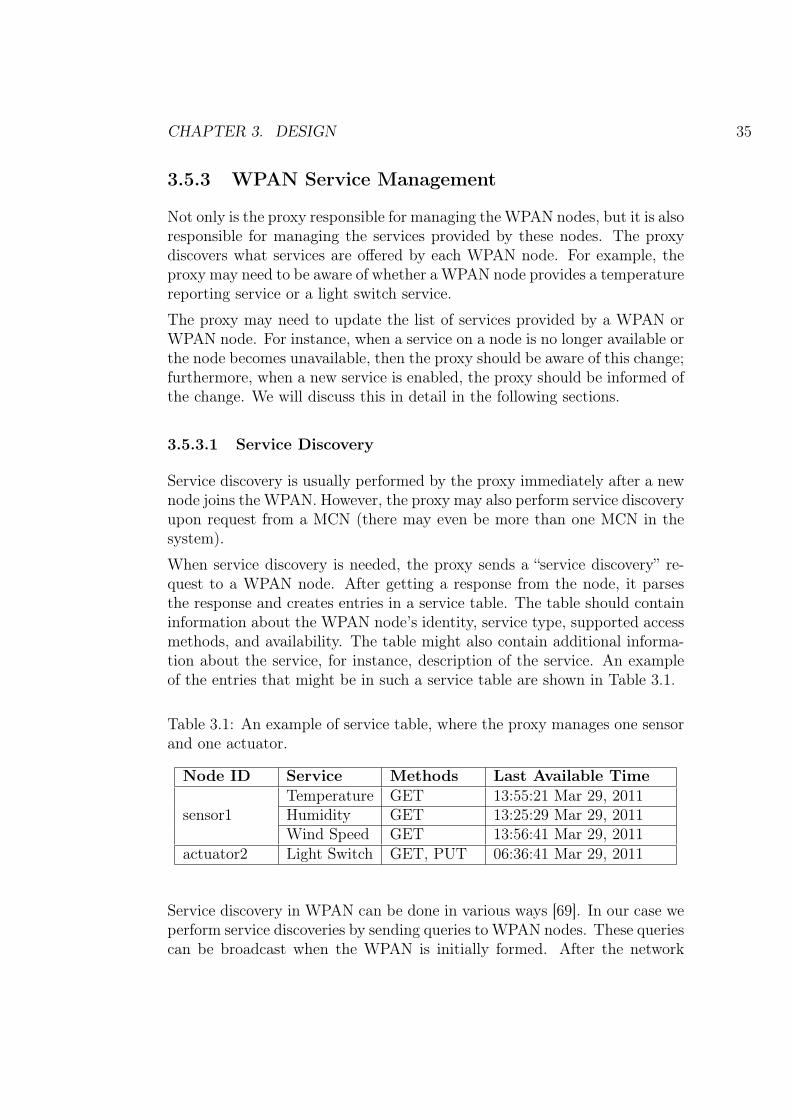
3.1 An example of service table, where the proxy manages onesensor and one actuator. . . . . . . . . . . . . . . . . . . . . . 35
viii

List of Figures
2.1 A multi-hop wireless sensor network. . . . . . . . . . . . . . . 7
2.2 The architecture of sensors. . . . . . . . . . . . . . . . . . . . 8
2.3 IEEE 802.15.4 specification in context. . . . . . . . . . . . . . 11
2.4 ZigBee stack architecture. . . . . . . . . . . . . . . . . . . . . 13
2.5 Illustration of a Chord ring. . . . . . . . . . . . . . . . . . . . 19
3.1 Overall architecture. . . . . . . . . . . . . . . . . . . . . . . . 23
3.2 Flow of communications between MCN and a single sensor(s)that returns the temperature that it has measured locally. . . 24
3.3 Proposed proxy architecture. . . . . . . . . . . . . . . . . . . . 27
3.4 Protocol stack of the proxy node. . . . . . . . . . . . . . . . . 28
3.5 The UML use case diagram of the proxy. . . . . . . . . . . . . 28
3.6 Node joining a ZigBee network. . . . . . . . . . . . . . . . . . 31
3.7 The “eagle” scheme in which the proxy polls WPAN nodes. . . 32
3.8 The “eagle” scheme in which WPAN nodes actively send keep-alive messages to the proxy. . . . . . . . . . . . . . . . . . . . 33
3.9 The “ostrich” scheme. . . . . . . . . . . . . . . . . . . . . . . . 33
3.10 Authentication and encryption in ZigBee packets. . . . . . . . 39
4.1 A Libelium Waspmote used in our implementation. . . . . . . 41
4.2 The hardware of the proxy prototype, where a Libelium Wasp-mote Gateway and a 3G dongle are connected to a GumstixOvero Earth through a USB hub. . . . . . . . . . . . . . . . . 42
ix

4.3 A prototype of the DHT-based M2M system, where a proxy isused to make WPAN nodes globally addressable and accessiblefrom a 3G WWAN. . . . . . . . . . . . . . . . . . . . . . . . . 44
4.4 A prototype used for our implementation. . . . . . . . . . . . 44
4.5 Waspmote application header. . . . . . . . . . . . . . . . . . . 46
5.1 A sample scenario implemented in our prototype, where a localWPAN sensor sends message to a WWAN actuator. . . . . . . 48
5.2 A sample scenario implemented in our prototype, where aWWAN sensor sends message to a local WPAN actuator. . . . 49
5.3 The number of nodes in the DHT does not significantly affectnode lookup time, but he stability of node looking up decreasesas the number of DHT nodes increases. . . . . . . . . . . . . . 50
5.4 RTT is affected more significantly by the size of CoAP mes-sages rather than the number of DHT nodes, when the major-ity of DHT nodes are virtual nodes residing on a single PC. . . 52
5.5 RTT between two WWAN nodes is not significantly influencedby CoAP message size, when CoAP messages are between 180and 300 bytes. . . . . . . . . . . . . . . . . . . . . . . . . . . . 53
5.6 RTT is affected by the size of CoAP messages when the systemhas 50 DHT nodes (48 of which are virtual nodes residing ona single PC). . . . . . . . . . . . . . . . . . . . . . . . . . . . 54
x

Abbreviations and Acronyms
3G 3rd Generation mobile telecommunications6LoWPAN IPv6 over Low-power Wireless Personal Area
NetworksACK AcknowledgmentAODV Ad hoc On-demand Distance VectorAPDU Application layer Protocol Data UnitAPI Application Programming InterfaceAPS Application support sub-layerAPSDE Application support sub-layer data service entityAPSME Application support sub-layer management service
entityCoAP Constrained Application ProtocolCRC Cyclic Redundancy CheckCoRE Constrained RESTful Environments working groupCRUD Create, Read, Update and DeleteCSMA/CA Carrier Sense Multiple Access with Collision
AvoidanceDHT Distributed Hash TableDDNS Distributed Domain Name ServiceDNS Domain Name ServiceDVI Digital Visual InterfaceEEPROM Electrically Erasable Programmable
Read-Only MemoryERP Enterprise Resource PlanningFFD Full-Function DeviceGAF Geographic Adaptive FidelityGEAR Geographic and Energy-Aware RoutingGPRS General Packet Radio ServiceGPS Global Positioning SystemHTTP Hypertext Transfer Protocol
xi

ICT Information and Communication TechnologiesIDE Integrated Development EnvironmentIETF Internet Engineering Task ForceIoT Internet of ThingsIP Internet ProtocolIPC Inter-Process CommunicationLEACH Low-energy adaptive clustering hierarchyLLC Logical Link ControlLR-WPAN Low-Rate Wireless Personal NetworkLoWPAN Low-power Wireless Personal NetworkM2M Machine-to-MachineM2M CE Machine-to-Machine Communication EnablerMAC Medium Access ControlMCN Monitoring and Control NodeMD5 Message-Digest algorithm 5MECN Mminimum Energy Communication NetworkMIC Message Integration CodeOS Operating SystemOSI Open Systems InterconnectionOTAP Over The Air ProgrammingP2P Peer-to-PeerPAN Personal Area NetworkPC Personal ComputerPDU Protocol Data UnitPEGASIS Power-efficient GAthering in Sensor Information
SystemsPHY Physical LayerQoS Quality of ServiceREST Representational State TransferRFD Reduced-Function DeviceRFID Radio-Frequency IDentificationRISC Reduced Instruction Set ComputingRMI Remote Method InvocationRPC Remote Procedure CallRTT Round Trip TimeSAR Sequential Assignment RoutingSCM Supply Chain ManagementSHA Secure Hash AlgorithmSMECN Small Minimum Energy Communication NetworkSNMP Simple Network Management Protocol
xii

SPIN Sensor Protocols for Information via NegotiationSRAM Static Random-Access MemoryTEEN Threshold sensitive Energy Efficient sensor Network
protocolUDP User Datagram ProtocolUML Unified Modeling LanguageURI Universal Resource IndicatorUSB Universal Serial BusWAN Wide Area NetworkWPAN Wireless Personal Area NetworkWSN Wireless Sensor NetworkWWAN Wireless Wide Area NetworkZDO ZigBee Device Object
xiii

Chapter 1
Introduction
1.1 Overview
Wireless sensor networks (WSNs) have been of increasingly interest for bothresearchers and entrepreneurs. While WSN technologies have gradually ma-tured and more and more uses of WSNs have been reported, still most ofcurrent WSNs are designed only for specific purposes. For example, oneWSN may be used to gather information from a field, but the collected datais not immediately available to other parties.
As the concept of Internet of Things (IoT) and Machine-to-Machine (M2M)communications have developed, more and more scenarios have been sug-gested for them. However, current M2M systems may not fit into scenarioswhere a large number of WSNs and actuator nodes are required to commu-nicate with each other; for example, a smart traffic control scenario wheresensors monitor traffic volume and road condition in one place and may needto communicate with actuators several kilometers away. Who makes the de-cisions to change traffic lights based on the information collected by thosesensors? As a result, we propose a distributed hash table (DHT) based M2Msystem for interconnecting different M2M networks in order to make full useof information collected from currently available WSNs.
In the rest of this chapter we first introduce the problem we are trying totackle. Next we list the expected contributions of this thesis project. Finallywe describe how this thesis is organized.
1

CHAPTER 1. INTRODUCTION 2
1.2 Problem Description
Current M2M networks are often used to capture events and translate theminto human intelligible information. For example, WSNs are used to gatherinformation within a specific area. These networks usually have a hierarchicalor mesh topology. The sensor nodes are organized into clusters; the nodesgenerally communicate at low bit rate and strive for low power consumption.Low-Rate Wireless Personal Area Network (LR-WPAN) protocols, such asIEEE 802.15.4 (see Section 2.4), are usually used in these scenarios. M2Mnetworks are good for gathering information, but maybe not be sufficient forthe case of several M2M networks needing to exchange information with eachother, when centralized servers are not available to control the exchange ofinformation.
In this thesis project we will connect M2M networks to a wide area networkusing a Peer-to-Peer (P2P) overlay. Additionally, the nodes in the systemare not only sensors, but could also be actuators (a given node might evensupport both functions at the same time). The nodes share information col-lected from environments around them over a wide area network (WAN) inorder to make independent decisions and perform operations on their envi-ronment. This P2P network consists of proxies complemented by traditionalWSNs that forward data to these proxies. The P2P network will be imple-mented using DHT technology.
For this project, we will design, implement, and evaluate a proxy implement-ing DHT-based M2M communication. Such a proxy should make it possibleto incorporate inexpensive sensors/actuators as part of the DHT network.The proxy nodes are 3G-enabled sensors/actuators. In practice, each proxyis implemented by adding logic (software) to both cheap LR-WPAN sensorsand/or 3G-enabled proxy sensors/actuators.
1.3 Contributions
The contributions of this thesis include use of DHT in M2M systems in orderto increase scalability, a justification for introducing a proxy in DHT-basedM2M systems, a design for such a proxy, a working prototype with minimumfunctionality, and an evaluation of this prototype.

CHAPTER 1. INTRODUCTION 3
1.4 Thesis Organization
Chapter 2 discusses related concepts that the user will find useful when read-ing the remainder of the thesis. We introduce basic terms and technologies,including Internet of Things (Section 2.1), Machine-to-Machine communica-tion (Section 2.2), Wireless Sensor Networks (Section 2.3), Low-Rate WirelessPersonal Area Network protocols (Section 2.4), and Distributed Hash Tables(Section 2.5).
In Chapter 3 we describe the design decisions concerning our proxy. Specif-ically we will consider aspects of wireless personal area network(WPAN)’snode management and service management.We also discuss caching mecha-nisms used in the proxy and security related issues.
Chapter 4 describes the implementation of the proxy, including specific tech-nologies and techniques we used in the implementation.
Chapter 5 analyzes the prototype proxy implemented in this thesis projectand discusses performance considerations that should be taken into account.
We state our conclusions in Chapter 6. We summarize what has been doneand our results. The thesis closes with a discussion about what future im-provements are needed or might be needed.
Chapter 2
Background
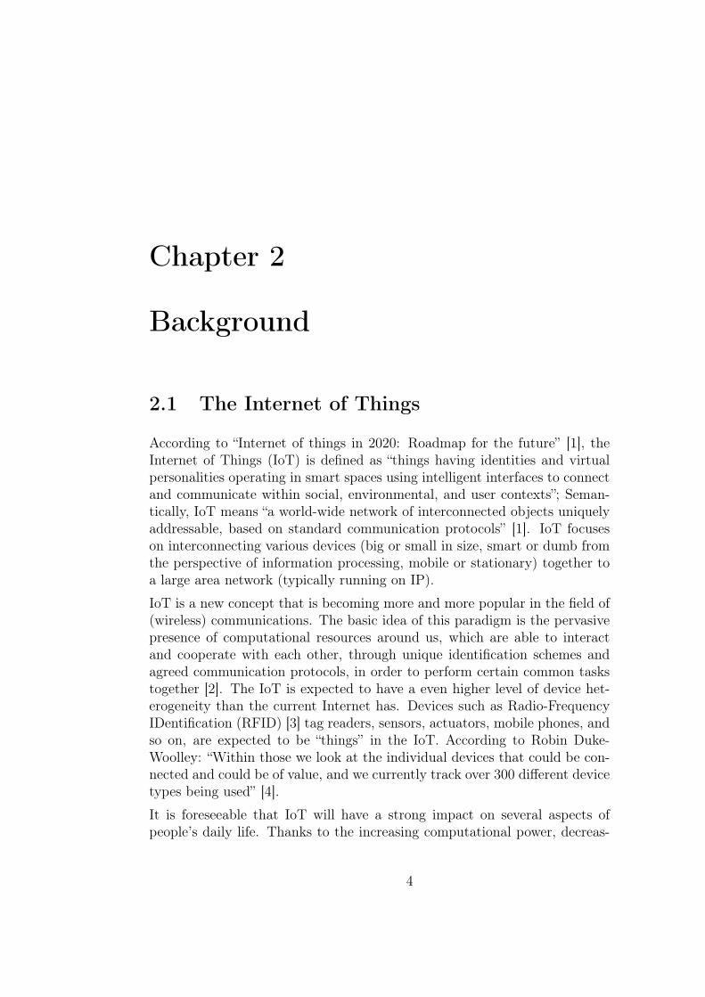
2.1 The Internet of Things
According to “Internet of things in 2020: Roadmap for the future” [1], theInternet of Things (IoT) is defined as “things having identities and virtualpersonalities operating in smart spaces using intelligent interfaces to connectand communicate within social, environmental, and user contexts”; Seman-tically, IoT means “a world-wide network of interconnected objects uniquelyaddressable, based on standard communication protocols” [1]. IoT focuseson interconnecting various devices (big or small in size, smart or dumb fromthe perspective of information processing, mobile or stationary) together toa large area network (typically running on IP).
IoT is a new concept that is becoming more and more popular in the field of(wireless) communications. The basic idea of this paradigm is the pervasivepresence of computational resources around us, which are able to interactand cooperate with each other, through unique identification schemes andagreed communication protocols, in order to perform certain common taskstogether [2]. The IoT is expected to have a even higher level of device het-erogeneity than the current Internet has. Devices such as Radio-FrequencyIDentification (RFID) [3] tag readers, sensors, actuators, mobile phones, andso on, are expected to be “things” in the IoT. According to Robin Duke-Woolley: “Within those we look at the individual devices that could be con-nected and could be of value, and we currently track over 300 different devicetypes being used” [4].
It is foreseeable that IoT will have a strong impact on several aspects ofpeople’s daily life. Thanks to the increasing computational power, decreas-
4

CHAPTER 2. BACKGROUND 5
ing size, and increased energy efficiency of the devices, and their inter-connectivity and interoperability, the IoT will play a role in numerous sce-narios. From the perspective of a private person, the IoT can be used inboth work and home environments. For example, users may employ the IoTfor health monitoring and for assisted living. Additionally, from the perspec-tive of businesses, IoT will have a high impact on fields such as industrialmanufacturing, automation, logistics, process management, and so on.
IoT will be ubiquitous, penetration into our life even more than the Internetand mobile technologies have. The number of devices that will form theIoT could be huge. According to Ericsson, there will be 50 billion connecteddevices by 2020 [5]. In comparision, today about 5 billion users are connectedto mobile networks worldwide. In other words, we will expect a shift of focusfrom person-to-person communication to pervasive M2M communication.
Some devices in the IoT will be intelligent and will exhibit behaviors accord-ing to predefined routines. Furthermore, some devices will have the abilityto collaborate with each other in a more intelligent manner, i.e. they may beable to make decisions based upon their environment by themselves or in col-laboration with other devices, instead of human users explicitly controllingthem. In addition to acting on their own, devices can also gather informationand deliver it to users of applications. For example, a device could send analarm message to its owner when its battery power level is low in the formof a text message sent to the owner’s cellular phone.
One of the most challenging issues in IoT is device power consumption, aswe expect a large number of battery powered devices to be connected tothe IoT. Due to limitations such as tiny physical size, harsh environment,absence of human intervention, and so on, it is important to efficiently utilizeavailable power resources. Another issue is reliability. We do not want torequire devices to be extremely reliable, because ensuring the reliability ofan individual device may cost a lot. However, the reliability of a group ofdevices trying to accomplish a common task can be much higher than theirindividual reliabilities. To achieve this, the devices in the IoT should beadaptive to failures of others and be able to self-configure. Furthermore,since the number of devices in the IoT will be large, individually configuringdevices will simply not be feasible in practice.
Despite the excitement of imagining the wonderful vision of the IoT, weneed to tackle the two challenges mentioned above before this vision can berealized. Mellor [6] expects that it will take a while before the M2M commu-nications and wireless sensor networks are deployed pervasively. While thereare existing M2M technologies, they are still under development and do not
CHAPTER 2. BACKGROUND 6
work well with each other. We will explore more about these two challengesin the following two sections.
2.2 Machine-to-Machine Commmunication
Machine-to-Machine (M2M)1 commmunication generally refers to commu-nication between machines, as opposed to communication between humanbeings, or communication between humans and machines. Because of the in-creasing amount of M2M commmunication, the “internet of things” is emerg-ing as a new paradigm.
M2M communications is based on the idea that rather than having a fewstand alone machines, interconnecting machines with each other is more use-ful [7, 8]. M2M systems combine Information and Communication Technolo-gies (ICT) with smart objects, to provide interaction among systems withouthuman intervention [9]. These automated systems can perform a variety oftasks.
M2M is a broad concept and has many application scenarios [10]. M2M “cov-ers an enormous number of potential devices and applications,” according toRobin Duke-Woolley at Harbor Research2. Harbor Research regularly mon-itors eight different markets – buildings, energy, industrial, medical, retail,transportation, security/public safety and consumer/professional – so as totrack M2M’s progress [4].
A typical M2M system has five basic components: users, objects, network,service platform, and enterprise information system [9]. These are describedas:
• Users – can be individual persons or other objects that make use ofthe system.
• Objects – such as sensors and actuators that can communicate withinternal peers and external peers.
• Network – the communication network enables objects to communicateeither internally with peers or externally with users. This network maybe a wired or wireless network.
1 M2M is sometimes interpreted as Man-to-Machine, Machine-to-Man, Machine-to-Mobile, or Mobile-to-Machine. In this thesis we only refer Machine-to-Machine as M2M.
2http://www.harborresearch.com/

CHAPTER 2. BACKGROUND 7
• Service platform – controls data routing as well as administration ofthe communicating participants. The service platform provides a mid-dleware layer that can optimize data flow among objects and providesservices and interfaces to applications.
• Enterprise information system – integrates the M2M solution with en-terprise applications such as Enterprise Resource Planning (ERP), Sup-ply Chain Management (SCM), and so on.
2.3 Wireless Sensor Networks
Wireless sensor networks (WSNs) have become increasingly popular in recentyears, as both the power consumption of sensor nodes and their cost havedecreased [11]. WSNs are widely deployed in many application areas [11,12], such as industrial control and monitoring, home automation, securityand military sensing, inventory management and asset tracking, environmentsensing, health monitoring, and so on.
2.3.1 WSN Architecture
In a WSN, sensor nodes are scattered over a sensor field. These nodes gatherinformation and transmit this information to a sink node perhaps via othersensor nodes. As shown in Figure 2.1, the sink acts as a gateway, exchanging
Sink
User(Task manager)
Internet/Satellite
Sensor field
Sensor
Figure 2.1: A multi-hop wireless sensor network.
data with a task manager node through the Internet or a satellite connec-tion [11]. The user may have some specific requirements for the sensor nodes.The user sends requests to the sink rather than directly to the sensor nodes.

CHAPTER 2. BACKGROUND 8
WSNs can be very different from other wireless networks, such as wireless adhoc networks [13]. WSNs have several distinct features as compared with adhoc networks [11]. First of all, in a WSN there are usually a large numberof sensors deployed in a field, frequently orders of magnitude more than thenumber of nodes in an ad hoc network. Secondly, unlike ad hoc network, WSNnodes are more prone to failure. Thirdly, the topology of WSNs, especiallythose where the sensor nodes are sparsely deployed [14], is likely to change, assensor nodes fail. Due to changes in network topology, the sensor nodes haveto re-self-organize in order to send data to the sink (gateway). Finally, theenergy available to a WSN node is limited, and recharging after deploymentis usually very difficult or impossible. As a result of the limitations on nodeenergy power management is a major issue in WSNs.
Due to the above features, WSNs are designed to take these many aspectsinto account. Generally, WSNs have to be fault tolerant since sensor nodefailures are common; they should be scalable because the number of nodesin the networks can be very large; and they have to be cost-effective – oth-erwise there would be little benefit in deploying WSNs; and they must bepower-efficient and resource-efficient, due to limitations on the size of the in-dividual sensor nodes and other constraints such as cost and environmentallimitations.
2.3.2 WSN Sensor Node Architecture
As shown in Figure 2.2, a sensor is composed of four main units [11]: a sensing
Figure 2.2: The architecture of sensors.

CHAPTER 2. BACKGROUND 9
unit for information gathering, a processing unit for processing information,a transceiver for communication with other nodes, and a power unit to supplyenergy.
Optional modules such as a power generator, location finding system, mobi-lizer and so on, may be added to this architecture, based on requirements ofthe actual application. Generally speaking, these modules have to interactwith the power unit on a node, i.e., they either provide power to the powerunit or consume power provided by the power unit.
2.3.3 Routing in WSNs
Finding the appropriate path to transfer data is very important in WSNs.Both data transfer and the routing protocol should use as little power aspossible, since power in sensor nodes is a limited resource. Additionally,the communication processing should not require too much computation ormemory, since these are also limited resources, especially if we want to achievelow cost for sensor nodes. As noted previously, the WSN itself should be self-organized. The environment of the sensor field may change, changing boththe topology and the set of events that need to be reported. Since generallysensor nodes are left unattended, they must find a valid path from each sensornode to the sink by themselves.
Akkaya and Younis [15] categorize routing protocols in WSNs into the fol-lowing four categories:
1. Data-centric protocols: They are query-based, thus they depend uponthe name of the data and the values of these named data. Redun-dant values of a named data item can be eliminated or aggregated.Mechanisms in this category include flooding and gossiping [16], sensorprotocols for information via negotiation (SPIN) [17], directed diffu-sion [18], etc.
2. Hierarchical protocols: These protocols focus on scalability. In hier-archical routing protocols, network clusters are established and thenetwork is divided into smaller subnetworks, easing management andincreasing scalability. Examples of hierarchical routing protocols arelow-energy adaptive clustering hierarchy (LEACH) [19], Power-efficientGAthering in Sensor Information Systems (PEGASIS) [20], Thresholdsensitive Energy Efficient sensor Network protocol (TEEN) [21], andso on.

CHAPTER 2. BACKGROUND 10
3. Location-based protocols: These protocols use knowledge of the phys-ical locations of sensor nodes. They take advantage of location infor-mation in an energy efficient way. They may be useful especially whenthere is no IP-address scheme and nodes are spatially deployed in a re-gion. Protocols falling into this category include minimum energy com-munication network (MECN) [22], small minimum energy communica-tion network (SMECN) [23], geographic adaptive fidelity (GAF) [24],geographic and energy-aware routing (GEAR) [25], and so on.
4. Network flow and QoS-aware protocols: Some protocols model routesetup process as a network flow problem. For example, maximum life-time energy routing [26] and maximum lifetime data gathering [27]fit into this category. QoS-aware protocols take end-to-end delay re-quirements into consideration while setting up routes in the network.Sequential assignment routing (SAR) [28] is an example of a QoS-awareprotocol.
2.4 Protocols for Wireless Sensor Networks
This section describes WSNs that utilize IEEE 802.15.4 network protocols.We first introduce the standard making community, the IEEE 802.15.4 work-ing group. Next we look at the IEEE 802.15.4 standard, which specifiesLow-Rate Wireless Personal Networks (LR-WPANs). After that we look atupper layer protocols that operate over an underlying IEEE 802.15.4 link.We introduce ZigBeeTMin Section 2.4.3 and 6LoWPAN in Section 2.4.4.
2.4.1 IEEE 802.15 Working Group
The IEEE 802.15 Working Group3 focuses on the development and stan-dardization of Wireless Personal Area Networks (WPAN)4, or short distancewireless networks.
This working group is organized into distinct sub-groups. IEEE 802.15WPAN Task Group 1 (TG1)5 focuses on standards based on BluetoothTM
technology; while the IEEE 802.15 WPAN Task Group 4 (TG4)6 is char-3http://www.ieee802.org/15/4http://www.ieee802.org/15/about.html5http://www.ieee802.org/15/pub/TG1.html6http://www.ieee802.org/15/pub/TG4.html

CHAPTER 2. BACKGROUND 11
tered to focus on WSNs [29], specifically the LR-WPAN standard for lowcomplexity, low cost, and extremely low-power wireless connectivity.
2.4.2 IEEE Std 802.15.4TM
After low data rate technology emerged the IEEE 802.15.4 committee beganto work on a low data rate standard. IEEE Std 802.15.4TM is a standard de-veloped and maintained by the IEEE 802.15 WPAN Task Group 4. The latestversion of this standard is IEEE Std 802.15.4-2006 [30], which is backward-compatible with IEEE Std 802.15.4-2003 [31]. It specifies the lower layersin the open systems interconnection (OSI) model [32]: the wireless MediumAccess Control (MAC) and Physical Layer (PHY) for LR-WPANs, as shownin Figure 2.3. Note that IEEE 802.15.4 operates under the IEEE LogicalLink Control (LLC) protocol.
Figure 2.3: IEEE 802.15.4 specification in context.
There may be two different types of devices participating in an IEEE 802.15.4network: full-function devices (FFDs) and reduced-function devices (RFDs).An FFD may serve as a coordinator in a network or as device; it can commu-nicate with other FFDs and RFDs. In contrast, an RFD may only talk to anFFD. Two or more devices within a personal operating space communicat-ing on the same wireless channel can form a WPAN. IEEE 802.15.4 WPANssupport star, tree, cluster tree, and mesh topologies.
IEEE Std 802.15.4-2006 specifies four different data rates for LR-WPANs:250 kb/s, 100 kb/s, 40 kb/s, and 20 kb/s. Other characteristics of LR-WPANs include star or peer-to-peer topologies; 16-bit short addresses or
CHAPTER 2. BACKGROUND 12
64-bit extended address space; carrier sense multiple access with collisionavoidance (CSMA/CA) channel access, low power consumption; 16 channelsin the 2450 MHz band, 30 channels in the 915 MHz band, and 3 channels inthe 868 MHz band; and so on.
The PHY of a device is implemented by a radio transceiver. The PHY layeris responsible for activation and deactivation of the radio transceiver, channelselection, data transmitting and receiving via the physical medium, and soon. The radio operates in unlicensed bands (meaning that the user does nothave to have a license to operate the device, but the manufacturer needs tomeet the requirements of the regulators), e.g. 868 – 868.6 MHz in Europe,902 – 928 MHz in North America, and 2400 – 2483.5 MHz world wide [30].
The MAC layer provides addressing and physical channel access for upperlayers. Its features include beacon management, channel access, associationand disassociation, and so on [30]. It manages all access to the physicalradio channel and is responsible for generating network beacons on coordina-tor devices, synchronizing to network beacons, supporting PAN associationand disassociation, employing the CSMA/CA mechanism for channel access,providing link reliability between two peer MAC entities, and so on [30].
On top of the MAC layer is a service-specific convergence sublayer (SSCS),providing the IEEE 802.2 logical link control (LLC) Layer access to the MAClayer. The IEEE 802.2 LLC layer further provides addressing and physicalchannel access for upper layers.
2.4.3 ZigBeeTM
ZigBeeTM is a low data rate, low power consumption wireless protocol in-tended for automation and remote control and monitoring [33]. The ZigBeeAlliance7 was established in 2002, in order to “develop standards that ulti-mately deliver greater freedom and flexibility for a smarter, more sustainableworld” [34]. ZigBeeTM is developed on top of IEEE Std 802.15.4-2003 [31]and supports only star, tree, and mesh topologies. That is, ZigBee does notsupport cluster tree network topology [35].
IEEE and the ZigBee Alliance have worked closely during the standardizationprocess. However, these two communities have different foci. The IEEE802.15.4 Working Group mainly focuses on the physical and data link layerof the protocol stack; while the ZigBee Alliance focuses on specifying theupper layers (from the network layer and above, see Figure 2.4), in order to
7http://www.zigbee.org/

CHAPTER 2. BACKGROUND 13
MAC
NWK
IEEE 802.15.4 Specification
Security Service Provider
PHY
Application Support Sublayer
ApplicationFramework
ZigBeeDevice Object
Application Layer
ZDOMangement
ZigBee SpecificationAPSDEAPSME
Figure 2.4: ZigBee stack architecture.
provide inter-operable networking, security services, application interfaces,as well as marketing and engineering evolution of the ZigBeeTM standard.
The ZigBeeTM network layer is designed to facilitate power conservation andto ensure low latency. It provides functionality to control and utilize theMAC layer as well as a service interface to the application support sub-layer (APS) above it. The ZigBee network layer is responsible for starting anetwork, assigning node addresses, configuring new devices, discovering otherZigBee networks, and applying security policies [35].
The APS provides an interface between the network layer and the applicationlayer [36] by providing services that are offered by two entities: the dataservice entity (APSDE) and the management service entity (APSME). TheAPSDE enables the transportation of application protocol data units (PDUs)between devices. The services APSDE provides include:
1. Generation of the application level PDUs (APDUs) – adding an appro-priate protocol header to APDUs and generating APS PDUs.
2. Binding – creating a unidirectional logical link between a source endpoint-cluster identifier pair and a destination endpoint. The APSDE is ableto send messages from one device to another once these two devices arebound.
3. Group address filtering based on endpoint group membership.

CHAPTER 2. BACKGROUND 14
4. Reliable transport – providing transaction reliability by employing end-to-end retries.
5. Duplicate packet rejection.
6. Fragmentation – segmentation and reassembly of APDUs longer thanthe payload of a single network layer packet.
The application layer in ZigBee consists of the application framework and theZigBee device object (ZDO). The application framework allows each ZigBeenode to define up to 240 application endpoints in order to transmit andreceive application data. The ZDO provides functions such as service anddevice discovery, coordinator initialization, security management, applicationendpoint binding management, and network management.
2.4.4 6LoWPAN
RFC 4919 [37] defines Low-power wireless personal area networks (LoW-PANs) as networks comprised of IEEE 802.15.4-2003 [31] devices, which arecharacterized by short range, low bit rate, small packet size, low power, andlow cost. A LoWPAN targets wireless connectivity for applications withlimited power and low throughput requirements.
It is beneficial to have IP working over IEEE 802.15.4 links, in that IP net-works are pervasive, proven to work, and built on open standards. Further-more, IPv6 [38] meets LoWPAN requirements in that IPv6 has solutions fornetwork auto-configuration and statelessness, which are desirable for LoW-PAN devices, and IPv6 supports a large address space as needed in LoW-PANs. In addition, IPv6 supports subsuming IEEE 802.15.4 MAC addresseswhen desired. Finally, IPv6 provides interconnectivity to other IP networks,e.g., the Internet.
However, there are several challenges when transferring IPv6 packets overIEEE 802.15.4 networks, because of the small frame size limitation and otherconstraints of LoWPANs. For example, there needs to be a fragmentationand reassembly layer below IP in order to transfer larger packets and thereshould also be a header compression mechanism in order to reduce overhead.
RFC 4944 [39] defines an adaption layer for enabling IPv6 on top of IEEE802.15.4 networks. It also defines header compression mechanisms makingIPv6 practical on IEEE 802.15.4 networks. However, RFC 4944 does notdeal with mesh routing specifications.

CHAPTER 2. BACKGROUND 15
2.4.5 CoAP
Constrained Application Protocol (CoAP) [40] is an application layer transferprotocol for resource constrained networks. CoAP is defined by the IETFConstrained RESTful Environments (CoRE) working group. CoAP can beused in M2M applications such as home automation, industrial automation,smart grids, and so on. Because of resource limitations of M2M nodes, CoAPis designed to have small message overhead. Hence, fragmentation is notallowed in CoAP. It realizes a subset of the Representational State Transfer(REST) protocol [41] common with HTTP [42].
It uses a method/response interaction model between different applicationendpoints, that is, CoAP messages contain either a method or response code,carrying a request or response semantics respectively. A request could eitherbe Confirmable or Non-confirmable. The response to a request is carried inan Acknowledgment when the requested response is immediately available.It is a piggy-backed response. When a response is not immediately available,an empty Acknowledgment is returned first. A new Confirmable message issent to the client when the response is ready. After receiving the responsethe client has to return an Acknowledgment.
CoAP also supports built-in resource discovery in order to facilitate M2Mapplications. This feature is very important for M2M applications sincethere are no humans in the M2M loop. To achieve this, the endpoints shouldconform to the CoRE Link Format [43] of discoverable resources. Resourcediscovery can either be unicast or multicast, which is useful when resourcesin a limited scope need to be located.
CoAP easily translates to HTTP since it supports a subset of HTTP func-tionality. It is useful for integration with web services. Sometimes an HTTPto CoAP mapping is necessary, for example, this can be implemented in aCoAP-HTTP proxy.
2.5 Distributed Hash Tables
A hash table or sometimes a hash map is a data structure that maps keys tovalues using a hash algorithm (see Section 2.5.1). A distributed hash table(DHT) is a hash table constructed and used in a distributed manner. A hashtable is easy to deploy in a distributed system since it places few constraintson the keys or data, nor how they are organized. Distributed system’s DHTsare maintained by the nodes in a network. These nodes act autonomously,

CHAPTER 2. BACKGROUND 16
i.e. nodes join or leave the network without any centralized control [44].
DHT relies on three main components: the key space, the key partitioningalgorithm, and the overlay network [44, 45]. The key space is the set of allpossible keys. The key splitting algorithm splits the key space into differentpartitions, which are the responsibility of different nodes. The overlay net-work connects the participating nodes so that the node storing a specific keyand its associated data can be found.
DHTs are widely used in peer-to-peer (P2P) systems for data lookup, sincea DHT implements just one function: looking up a key and returning the IDof the node responsible for this key. The major issues when implementing aDHT include the following three [46]:
1. Load balancing among nodes: keys should be evenly assigned to theparticipating nodes so that every node is responsible for roughly thesame number of keys. This assumes that each node has roughly thesame local resources; if they have unequal resources, then of course thekeys should be assigned proportional to the node’s share of the totalresource. This can be achieved using consistent hashing, as we willdiscuss in Section 2.5.2.
2. Forwarding lookups to appropriate nodes: when a node receives alookup request and does not have the requested content, it should for-ward the request to a node that is closer to the key so that the requestreaches the correct node. For example, when a node i receives a requestfor key k, which is greater than the node’s ID Ni, then this node shouldforward this request to another node j, such that Nj > Ni and Nj 6 k.
3. Building routing tables: every node keeps track of some other nodes inorder to forward requests to them. This can be done in various ways.We will look at one implementation, Chord, in Section 2.5.3.
2.5.1 Hash Algorithms
Hash functions are algorithms which transform a variable length (binary)string of data into a small fixed length item. Hash functions are lossy com-pression functions that can be used to generate a fingerprint for a certaininput. A widely used hash function is the MD5 [47] algorithm. The MD5algorithm converts a variable-sized input into a 128-bit message digest of theinput. It has been widely used since it was invented, for example the most

CHAPTER 2. BACKGROUND 17
common uses are checking the integrity of files, SSL/TLS [48], IPSec [49],pseudo random number generation [50], and so on.
2.5.2 Consistent Hashing
Before introducing consistent hashing, we first describe the phenomenon ofhot spots in a network. Hot spots happen when a single server receivesrequests from a large number of clients. This may overload the server, causinga denial of service, exponentially increasing load, increase probability of nodefailure, etc. The hot spot phenomenon is quite common with web services,when the service suddenly becomes very popular there may be more clientssimultaneously attempting to access the server than the server was designedto cope with [51].
One way to remedy the hot spot phenomenon is to use cache servers. A cacheserver sits between the clients and the server. When it receives a request froma client, it looks up the data being requested in its own cache. If the datais in the cache, then the data is returned to the client; otherwise the cacheserver has to contact other cache servers or the actual server for the data.
One problem with this traditional approach is that the system may not scale,and when one cache server fails or new cache servers are added to the system,the cache servers may need to remap their cached pages [52]. David Karger etal. [51] address this problem with random cache trees and consistent hashing.Random cache trees are used to coalesce requests from clients. Consistenthashing is employed to balance the load even with a fluctuating number ofcache servers. Consistent hashing tries to split items into sets so that everyset has roughly the same number of items; at the same time ensuring that:
1. A change in one set does not cause re-assignment of items to other sets;
2. Moving items from one set to another causes only slightly differentarrangements of the mapping of items to sets.
In contrast, a traditional hashing algorithm will cause all items to be remappedwhen the number of sets changes. Consistent hashing is used to enable easyre-assignment of keys to adjacent nodes when there is a loss or addition ofa node. Note that keys and values have to be stored redundantly, otherwisethe loss of a node leads to a loss of data. According to [53], consistent hash-ing ensures with high probability the minimum amount of remapping of keyswhen the N th node joins or leaves the network; in this case only O(1/N) of
CHAPTER 2. BACKGROUND 18
the keys need to be moved to a different node in order to balance the loadacross the nodes.
A consistent hashing algorithm is easy to implement [54]. First we need astandard hash function, such as cyclic redundancy checks (CRCs) [55], MD5,one of the SHA series of hash functions, e.g. SHA-1 [56], and so on. Thisfunction will map strings into numbers in the range [0, . . . ,M ], where M isthe number of sets. A consistent hashing function can be constituted bydividing the numbers by M so that every hash value falls into the interval[0, 1], thus the values can be mapped to a unit circle. In this way every string(item) is mapped to a single point on the circle. By mapping these hashingcache servers onto the same circle, we assign items to corresponding cacheservers, that is, every cache server is responsible for items between itself andthe previous cache server.
Consistent hashing is usually used in DHTs to map keys to nodes, thanksto the property that removal or addition of one node changes only the setof keys owned by the nodes with adjacent IDs, while leaving all other nodesunaffected [54].
2.5.3 Chord
Chord [53, 57] is a distributed lookup protocol for efficiently locating a nodethat stores certain data item in P2P applications. It addresses problems in-cluding load balancing, decentralization, scalability, availability, and flexiblenaming. In a N-node system, each Chord node stores information aboutO(logN) other nodes when the system is in steady state. Lookups are re-solved via O(logN) messages to other nodes. Nodes joining and leaving thesystem will result in no more than O(log2N) messages with high probability.
In Chord, each node has an ID and is mapped to a certain place in a circle [58],as shown in Figure 2.5. The predecessor of a node is the peer in front of itwhen traversing the circle clockwise. Likewise, the successor of a node isthe peer following it. For example, in Figure 2.5 node N2’s predecessor andsuccessor are N0 and N3 respectively. Each node is responsible for datawith a key between the predecessor’s ID and its own ID. For example, inFigure 2.5 node N2 is responsible for data with a key K1.
Each Chord node contains a routing table (or finger table) about O(logN)other nodes in the half of the Chord ring clockwise from the node. The ith
entry in node Nn’s finger table contains the identity of the first successorthat is at least 2i−1 away from Nn on the ring. Each node also maintainsinformation about its predecessor. For example, the finger table of node

CHAPTER 2. BACKGROUND 19
Figure 2.5: Illustration of a Chord ring.
N2 in Figure 2.5 looks as Table 2.1. Routing in Chord is accomplished
Table 2.1: An example of Chord finger table.
Start SuccessorN2 + 1 N3N2 + 2 N4N2 + 4 N6Predecessor = N0
by querying the nearest finger of the key being looked up. Each routing hopreduces the distance on the circle/ring to the destination node approximatelyin half, thus ensuing efficient lookups.
When a node joins, it performs a lookup with its own node ID, treatingthe result as its successor. It then does lookups to locate its predecessorand updates its finger table. Its predecessor and successor will also updatetheir finger tables subsequently, during their periodic maintenance time slots.When a node plans to leave, it informs its immediate predecessor and suc-cessor and transfers its data items to its successor [58].

CHAPTER 2. BACKGROUND 20
2.6 Simple Network Management Protocol
The Simple Network Management Protocol (SNMP) [59] aims to providenode management functionality in the Internet. An SNMP managementsystem contains three components [60]:
1. Manager entities that generate commands and listen for responses.
2. Nodes that are managed by the manager. These nodes (agents) aresoftware processes that maintain information about themselves andtheir environment, as well as respond to commands received from man-agers. Agents often reside in network equipments such as network hubs,routers, and workstations.
3. A management protocol that conveys management information be-tween the managers and agents.
The SNMPv1 [59] protocol specifies five command, response, or alert PDUs:
1. GetRequest – A request sent from a manager to an agent to retrievethe value of a variable stored by the agent.
2. SetRequest – A request sent from a manager to an agent to change thevalue of a variable stored by the agent.
3. GetNextRequest – A request sent from a manager to an agent to discoverthe next available variable and its value as stored by the agent.
4. Response – A message sent from an agent to a manager in reply to afetch command such as GetRequest, SetRequest, GetNextRequest.
5. Trap – An unsolicited alert message sent from an agent to a managerwhen there is a significant event.
SNMPv2 specifies two more PDUs in RFC 1905 [61], namely GetBulkRequestwhich optimizes GetNextRequest, and InformRequest enabling acknowledgedasynchronous notification between managers.
2.7 Summary
In this chapter we have discussed concepts and technologies related to thisthesis. We summarize what we have covered as follows:
CHAPTER 2. BACKGROUND 21
• The IoT embraces heterogeneous devices into a worldwide networkbased on standard protocols. IoT will penetrate into our life morethan the current technologies have. By 2020 there will be 50 billionconnected to the IoT.
• M2M is a similar concept that intersects with IoT. M2M network gen-erally consists of smart objects interacting with each other without hu-man intervention. A typical M2M system has five basic components:users, objects, network, service platform, and enterprise informationsystem.
• WSNs are used for monitoring as well as control purposes, for exam-ple, industrial control and monitoring, home automation, security andmilitary sensing, and so on. Nodes in WSNs scatter over a sensor fieldand the number of sensor node is usually large. These nodes are proneto failure and the network topology may subject to change. Differentrouting protocols have been proposed to find an appropriate path totransfer data in WSNs. These routing protocols are categorized intofour categories: data-centric protocols, hierarchical protocols, location-based protocols, and network flow and QoS-aware protocols.
• IEEE Std 802.15.4 specifies the PHY and MAC layer for LR-WPANs.ZigBee is developed on top of IEEE Std 802.15.4 and it defines theupper layers (from the network layer and above) in the OSI model.ZigBee provides a stack profile standard that allows developers to createtheir own application profiles. The IEFT specifies 6LoWPAN as analternative to enable IPv6 on top of IEEE 802.15.4. Since 6LoWPANis only an adaption layer, CoAP is suggested as the application layerprotocol for M2M systems.
• A DHT is a hash table constructed and used in a distributed mannerin order to provide an efficient way of data lookup in highly scalableP2P systems. Chord is one of the DHT algorithms that yield goodperformance in load balancing, decentralization, scalability, availability,and flexible naming.
• SNMP is a protocol that provides node management functionality inthe Internet. It is specified by the IETF.
Chapter 3
Design
The goal of this thesis project is to connect resource constrained devicesto a larger network, for instance the Internet. In particular, we assume ascenario as shown in Figure 3.1. In this scenario, we assume a number ofLR-WPANs are scattered in different geographic locations. The distancefrom one WPAN to another can be tens of kilometers or more. Thus it isimpossible for nodes in one LR-WPAN to communicate with nodes in anotherWPAN. The WPAN nodes are assumed to be battery powered and have veryconstrained computational capability.
Under this assumption, one proxy node is introduced in each LR-WPAN inorder to connect the LR-WPANs together. This proxy node is both wire-less wide area network (WWAN) and WPAN enabled. It is responsible formanaging WPAN nodes that are in the same WPAN as the proxy, as wellas exchanging information with WWAN peers. Note that proxy nodes mayalso have sensor or actuator modules attached to them. The proxy nodeshave fewer resource constraints as compared with WPAN sensors/actuators,and they will mostly be mains powered. However, the power consumption ofthese nodes are relatively low compared with personal computers, and theyhave less computational capability.
To ensure scalability, a DHT overlay is used and all proxy nodes as well asother WWAN nodes are connected to this DHT overlay network. DHT isused for node lookup (resembling the functionality of a domain name system(DNS)) and resource locating. A M2M Communication Enabler (M2M CE)provides functionality to translate a resource URI to a responsible proxynode’s IP address. However, the functionality of M2M CE is not within thescope of this thesis project.
Furthermore, a monitoring and control node (MCN) is used to gather infor-
22

CHAPTER 3. DESIGN 23
Figure 3.1: Overall architecture.
mation from end WPAN nodes and proxies, as well as to send commandsto them in order to configure the system. The MCN may not be online allthe time. However, it has to be in the DHT overlay in order to easily accessboth the WWAN nodes and WPAN nodes. The communication between theMonitoring and Control Node (MCN) and the sensor nodes looks roughly asFigure 3.2.
To simplify the problem, we assume the underlying WWAN link technol-ogy is a 3G connection, since it is mature technology and easily accessible.For the LR-WPAN communication we choose ZigBee over 6LoWPAN andother technologies based on IEEE 802.15.4, because ZibBee devices are morepopular in the market.
CHAPTER 3. DESIGN 24
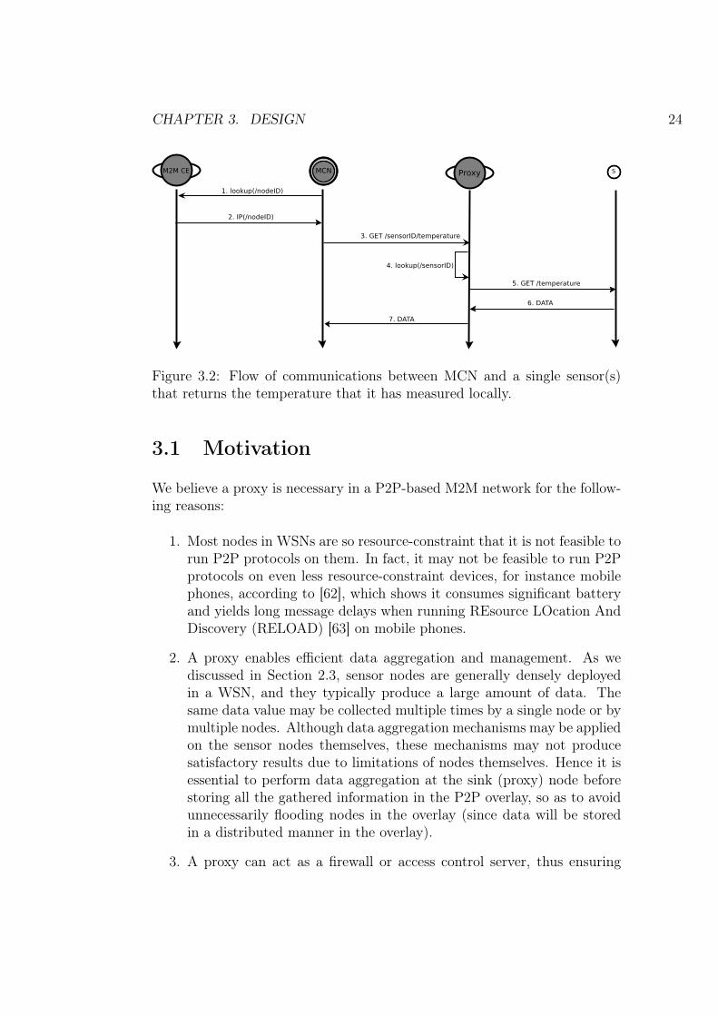
Figure 3.2: Flow of communications between MCN and a single sensor(s)that returns the temperature that it has measured locally.
3.1 Motivation
We believe a proxy is necessary in a P2P-based M2M network for the follow-ing reasons:
1. Most nodes in WSNs are so resource-constraint that it is not feasible torun P2P protocols on them. In fact, it may not be feasible to run P2Pprotocols on even less resource-constraint devices, for instance mobilephones, according to [62], which shows it consumes significant batteryand yields long message delays when running REsource LOcation AndDiscovery (RELOAD) [63] on mobile phones.
2. A proxy enables efficient data aggregation and management. As wediscussed in Section 2.3, sensor nodes are generally densely deployedin a WSN, and they typically produce a large amount of data. Thesame data value may be collected multiple times by a single node or bymultiple nodes. Although data aggregation mechanisms may be appliedon the sensor nodes themselves, these mechanisms may not producesatisfactory results due to limitations of nodes themselves. Hence it isessential to perform data aggregation at the sink (proxy) node beforestoring all the gathered information in the P2P overlay, so as to avoidunnecessarily flooding nodes in the overlay (since data will be storedin a distributed manner in the overlay).
3. A proxy can act as a firewall or access control server, thus ensuring

CHAPTER 3. DESIGN 25
security of the system. Instead of exposing all the sensor nodes to thelarger network, i.e. the Internet, the proxy controls which resourcesin the WSN can be accessed by another specific party. This kind ofsecurity control is more convenient than specifying security policies atthe individual sensor nodes, due to sensor node limitations.
4. Introducing a proxy into the system simplifies the design of applicationlogic on the WSN nodes. This design paradigm shifts the complexityof sensor nodes to proxies. Since the proxy nodes are supposed to bemore capable than the sensor nodes, it is straightforward to keep thesensor nodes simple and shift the complexity to the proxy.
5. A proxy can connect heterogeneous sensor nodes to the system. Thisis especially important for M2M networks, since nodes in the networkmay rely on different communication protocols. The proxy can bridgedifferent communication protocols, thus embracing various portions ofnetworks into the M2M system.
Although some of the above functionality may be realized by nodes otherthan a proxy; for example, a dedicated security server can be used to handleresource access control, we feel these mechanisms may again add complexityto the whole system. As a result,we try to keep the sensor node logic simpleand move all the complexity to proxy nodes, without complicating the M2Msystem too much.
3.2 Objective
The goal of this thesis project is to make WPAN nodes addressable fromthe WWAN. A proxy node bridges the communication between a WWANnode and a WPAN node. Thus, a WWAN node requests WPAN resourcesthrough the proxy node, and vice versa. In our case the proxy should havethe following capabilities:
1. WPAN node discovery: The proxy should be able to discover newWPAN devices when they are connected to the WPAN and announcethem to the DHT overlay if needed.
2. WPAN service discovery: The proxy should be able to discover theservices that each WPAN device provides. For instance, the proxyshould be aware of all services each sensor/actuator node supports.

CHAPTER 3. DESIGN 26
3. Retrieve information from WPAN nodes and WWAN nodes. For ex-ample, the proxy should be able to get information from and post datato sensors and actuators both in the WPAN or WWAN.
4. Process information gathered from WPAN nodes or WWAN nodes andstore this information to the DHT overlay (if required).
3.3 Principles
When designing the proxy, we have kept several principles in mind. Theseprinciples have clearly affected the design and implementation of the proxy.These principles are:
1. Power efficiency: The proxy should take power consumption into con-sideration when communicating with WPAN nodes, since the WPANnodes may have very limited energy on-board.
2. Interoperability: The proxy should enable heterogeneous devices tocommunicate with each other. We assume that the WPAN nodes mayhave different hardware architectures, operate over different underlyingcommunication protocols, or suit different application purposes. Theproxy should provide transparent access to the WPAN nodes from theWWAN nodes.
3. Scalability: The proxy should to be able to function well when thenumber of nodes in its WPAN increases. The proxy should not causelow responsiveness, long response times, service unavailability, etc., dueto the large number of nodes in the WPAN.
4. Security: The proxy should protect both the confidentiality and in-tegrity of the data collected by a WPAN node. It should also be able todetect potential security attacks and report unusual events to a MCN.
5. Reliability: The proxy should reply with reliable data upon requestfrom WWAN nodes. Furthermore, it should be aware of the unavail-ability of WPAN nodes and act accordingly in order to produce satis-fying results for the WWAN nodes.

CHAPTER 3. DESIGN 27
3.4 Architecture
Based on the above discussions, we present a system architecture as shownin Figure 3.3. In this architecture, the proxy provides the MCN with man-agement and data access to the WPAN nodes. The proxy intelligence is adaemon that listens to incoming requests, distinguishes different types of re-quests, and calls the corresponding APIs. The management API providesinterfaces for managing WPANs, WPAN security, and WPAN services. Thedata API provides interfaces for collecting data from the WPAN and deliv-ering commands to the WPAN.
SecurityManagement
WPANManagement
ServiceManagement
Management API
ZigBee
Caching
Data Service
Data API
Proxy Intelligence
IP
UDP
CoAP
M2M CEManagement Module
Figure 3.3: Proposed proxy architecture.
This proxy bridges the communication between a WWAN and a WPAN. Onthe WWAN (IP network) side, the proxy communicates with the managementmodule and M2M CE using protocols based on IP, such as SNMP and CoAP;on the WPAN (ZigBee network) side, the proxy communicate with WPANnodes using WPAN protocols, for example, ZigBee and CoAP (if 6LoWPANis the used in the WPAN). The protocol stack on a proxy node is shown inFigure 3.4.

CHAPTER 3. DESIGN 28
IEEE 802.15.4
UDP
SNMP
Proxy Logic
IP
DHT
M2M CE
3G / GSM
CoAP
ZigBee NWK
ZigBee APS
ZigBee APPZDO
Management Module
Proxy Node
Figure 3.4: Protocol stack of the proxy node.
3.5 Details
The unified modeling language (UML) [64] use case diagram of the proxyis shown in Figure 3.5. We will discuss the functionality in detail in thefollowing sections.
Figure 3.5: The UML use case diagram of the proxy.

CHAPTER 3. DESIGN 29
3.5.1 Proxy Joining and Leaving
The proxy itself has to be a part of the DHT overlay in order to make WPANnodes accessible from the DHT. As a result, the proxy should join the DHTfirst before announcing WPAN nodes to the DHT or revoking them from theoverlay.
To join the overlay, the proxy should have a CoAP URI, which can be pre-configured or configured using SNMP. When the proxy joins the DHT, itnegotiates with an M2M CE instance, which may either reside in the samenode or on a different node in the network. After it becomes a part of theoverlay, the proxy scans all the resources that are supposed to be visible inthe WWAN and announces them to the overlay, again via negotiations withan M2M CE instance.
To leave a DHT overlay, the proxy first revokes all the resources it has an-nounced to the overlay. Then it leaves the overlay itself. All operations onthe DHT overlay by the proxy are done through an M2M CE instance.
3.5.2 WPAN Management
The proxy is responsible for configuring the WPAN. It should allow or disal-low new WPAN devices joining the network. When a node leaves the networkor silently leaves – due to failure because of battery exhaustion or hardwarefailure, the proxy should detect that a node has left the network within asuitable time period ranging from a few seconds to possibly hours, dependingon the actual application scenario.
Another important aspect of WPAN management is ensuring security. Theproxy should enable secure data transmission among WPAN nodes. Thissecurity should ensure both data integrity and authenticity of the data. Wewill discuss more about system security in Section 3.5.5.
The proxy acts as the coordinator in the WPAN. It is responsible for theinitial configuration of each WPAN network. It selects an appropriate ZigBeePAN ID and operating frequency (radio channel), then configures securityoptions including encryption options and encryption keys. Details of theproxy’s operation will be described in more detail below.

CHAPTER 3. DESIGN 30
3.5.2.1 WPAN Start Up
To start up a ZigBee network, the proxy first performs a channel scan creatinga list of potential channels, while removing channels with excessive energylevels (i.e., these channels are already busy with other traffic) [65].
Next the proxy tries to select a PAN ID. To ensure that PAN ID is not alreadyin use the proxy performs a PAN scan by sending beacon broadcasts oneach potential channel. After it receives responses from nearby coordinatorsand routers that have already joined a network, it either randomly selects aavailable PAN ID or chooses a PAN ID specified by the upper layers.
Next the proxy will configure the network based upon any specified securitypolicies. To perform this configuration, the proxy sets whether security isenabled in the network, and if so generates the network security key and thetrust center link key. Follow this, the proxy configures the relevant encryptionoptions, such as whether to use a trust center and how to send the securitykey when each node joins the network.
The reason we co-locate the ZigBee PAN coordinator and the proxy is tominimize energy consumption. If the coordinator is placed in another node,then transmitting messages would consume more energy. All of these re-quirements on the proxy and coordinator implies that the node supportingthe proxy and coordinate should be mains powered.
3.5.2.2 Node Joining
In ZigBee networks routers and end devices can join an existing network. Inorder to join a network, the node has to configure itself with the PAN ID ofthe network that it wants to join, then perform a channel scan with a bit-mask containing the proxy’s operating channel. Additionally, this potentialnew node must have a security policy conforming to the proxy’s settings.
A node can only join a network if it has the correct PAN ID, pre-configuredsecurity keys, and the proxy permits this node to join the network. Wedemonstrate the process of a node joining a network in Figure 3.6. After theproxy starts up, initially there are no other nodes in the network. In orderfor the proxy to permit a node to join its network, the node’s parametersmust be configured to conform to the proxy network settings. Initially wewill assume that the user manually configures the sensor node, then sendsa “add node request” from the MCN to the proxy. The proxy should firstverify the request, then enable nodes to join the network. At this point thenode is able to join the network. Once this node has joined the network the

CHAPTER 3. DESIGN 31
Figure 3.6: Node joining a ZigBee network.
proxy will send an acknowledgment to the MCN.
After a node has joined the network, the proxy will keep a record of the newlyadded node – including what services it can provide. In order to do that, anode service discovery is performed, this will be discussed in Section 3.5.3.1.
3.5.2.3 Node Leaving
Some nodes may need to leave the WAPN. Generally speaking, there could betwo ways that a node leaves a network: explicit leaving and implicit leaving.Explicit leaving means that a node notifies the network that it intends toleave, while implicit leaving refers to the situation where the network is notexplicitly informed when a node leaves.
If a node leaves the network explicitly, then it sends a “leaving network”message to the proxy. This will cause the proxy to remove the node fromits list of “available nodes”. The M2M CE should also be notified about thechange in the network topology. Moreover, the MCN should be notified ofthis change.

CHAPTER 3. DESIGN 32
Implicit leaving is a bit more complicated. Two schemes may be used to findout whether a node is alive or not, depending on how aggressive the proxywishes to be.
Figure 3.7: The “eagle” scheme in which the proxy polls WPAN nodes.
The first scheme will be named the “eagle” scheme, in this scheme the keep-alive messages are used. The keep-alive messages can either be sent by theproxy (see Figure 3.7) or by the WPAN nodes (see Figure 3.8).
In the first case the proxy continually asks the nodes if they are alive or not.If the proxy does not receive an acknowledgement from a WPAN node duringa timeout period, then the proxy considers the WPAN node to be unavail-able. The keep-alive message interval can be configured by the managementmodule.
In the second case the WPAN nodes actively send keep-alive messages to theproxy without proxy polling. Similarly, when the proxy times out waitingfor a keep-alive message from a WPAN node, it treats that node as dead andinforms the DHT overlay via an M2M CE. Since the WPAN nodes control theintervals to send keep-alive messages, the proxy should be able to configurethis parameter by negotiating with the corresponding WPAN node. Thesolution for this may depend on the actual WPAN node, for example, thecommunication protocol and firmware of the node. This may be possible fornodes that support over the air programming (OTAP) [66].
Unfortunately, both cases in the “eagle” scheme consumes energy of both thetarget node and other nodes on the path to this node. However, this scheme

CHAPTER 3. DESIGN 33
WPAN node (sensor1)Proxy
Keep-Alive
Keep-Alive
Timeout
M2M CE
Node left: sensor1
Figure 3.8: The “eagle” scheme in which WPAN nodes actively send keep-alive messages to the proxy.
may be necessary for WPAN nodes that are critical for the system.
Figure 3.9: The “ostrich” scheme.
The second scheme will be named the “ostrich” scheme (see Figure 3.9), inthis scheme the proxy does not send keep-alive messages at all. Instead, theproxy queries a node only when data transmission is needed. If there are
CHAPTER 3. DESIGN 34
several consecutive missing acknowledgments, then the proxy considers thisnode to be dead and notifies the upper layers.
In order for the WPAN service to be more reliable, the proxy should providemechanisms to warn the MCN about potential failures that are going tohappen in a period of time. For instance, when the proxy detects a WPANnode has low battery level, it should report this to the MCN.
3.5.2.4 Naming, Addressing, and Routing
We use concepts of names, addresses, and routes conforming to those definedin [67]. A name denotes an entity and is usually human-readable. A routeis a list of names representing the path from one to another. An address isintended for machine processing and route generation.
Every entity has a human-readable CoAP name in our system. This nameis used whenever human users are involved in the loop, for instance, when auser configures which node a sensor should report to when certain thresholdsare met. More specifically, CoAP names are used mainly by the MCN, viawhich human users communicate with the M2M system.
The DHT overlay acts as a distributed domain name service (DDNS) system,translating CoAP names to addresses. Since our DHT overlay relies on IP,the CoAP names are always mapped to an IP address, that is, names ofproxy nodes and WWAN nodes map to IP addresses (of themselves), andnames of WPAN nodes map to the IP addresses of their proxies. Each proxyis responsible for translating names of WPAN nodes to their correspondingaddresses, in our case, their 16-bit WPAN addresses or 64-bit link addresses.
Routing in IP networks is not a major concern of this thesis, as we utilizethe current network infrastructure; otherwise routing in WPANs dependson the use and functionality of the WPAN. For instance, many-to-one rout-ing [65] is suitable for scenarios where many nodes send data to a singlecentral collector. For use cases where a node sends data to many othernodes, source routing can result in low packet delays and good network per-formance. Generally speaking, mesh routing mechanisms based on ad hocon-demand distance vector (AODV) [68] can also be appropriate for meshnetworks.
CHAPTER 3. DESIGN 35
3.5.3 WPAN Service Management
Not only is the proxy responsible for managing the WPAN nodes, but it is alsoresponsible for managing the services provided by these nodes. The proxydiscovers what services are offered by each WPAN node. For example, theproxy may need to be aware of whether a WPAN node provides a temperaturereporting service or a light switch service.
The proxy may need to update the list of services provided by a WPAN orWPAN node. For instance, when a service on a node is no longer available orthe node becomes unavailable, then the proxy should be aware of this change;furthermore, when a new service is enabled, the proxy should be informed ofthe change. We will discuss this in detail in the following sections.
3.5.3.1 Service Discovery
Service discovery is usually performed by the proxy immediately after a newnode joins the WPAN. However, the proxy may also perform service discoveryupon request from a MCN (there may even be more than one MCN in thesystem).
When service discovery is needed, the proxy sends a “service discovery” re-quest to a WPAN node. After getting a response from the node, it parsesthe response and creates entries in a service table. The table should containinformation about the WPAN node’s identity, service type, supported accessmethods, and availability. The table might also contain additional informa-tion about the service, for instance, description of the service. An exampleof the entries that might be in such a service table are shown in Table 3.1.
Table 3.1: An example of service table, where the proxy manages one sensorand one actuator.
Node ID Service Methods Last Available Time
sensor1Temperature GET 13:55:21 Mar 29, 2011Humidity GET 13:25:29 Mar 29, 2011Wind Speed GET 13:56:41 Mar 29, 2011
actuator2 Light Switch GET, PUT 06:36:41 Mar 29, 2011
Service discovery in WPAN can be done in various ways [69]. In our case weperform service discoveries by sending queries to WPAN nodes. These queriescan be broadcast when the WPAN is initially formed. After the network

CHAPTER 3. DESIGN 36
becomes more stable, unicast queries are sent to specific nodes instead of thewhole network.
We are able to use ZigBee ZDO functionality. For example, ZDO providescommands to request node descriptors from a ZigBee device, active end-points in a node and simple descriptor of a specific endpoint. Similarly, forWPANs running on 6LoWPAN, CoAP with CoRE link format [43] providesmechanisms to perform resource discovery. For general purpose WPANs,SensorML [70] provides an XML encoding for describing any processes andresources specifically for sensor networks.
The proxy is not required to inform the M2M CE or the MCN of servicetable changes, since this table could constantly change. Constantly updatingthe overlay of table changes may cause flooding in the overlay and mayunnecessarily consume energy at the proxy as well (although the proxy ismains powered, energy efficiency should always be a concern). On the otherhand, when certain critical services go down, it is necessary for the proxy toinform upper layers. We will discuss this in the following section.
3.5.3.2 Service Updates
The proxy does not have to inform the overlay about all changes that occur inthe service table. However, if critical changes occur in the service table, thenthe M2M CE or the MCN should be notified. Therefore, in the service tablewe keep track of all the critical services. Once a critical service is detectedto be unavailable, then a notification will be immediately sent to the M2MCE.
When a service is required to be actively turned off, then the proxy will markthe status of this service as “Not Available”. This can be done by sendinga request from the MCN to the proxy, requesting that specific services beturned off. Similarly, the proxy may enable services, thus an MCN can turnon (or off) specific services. Upon receiving an indication of unavailableservices for a request, an error message will be returned to the sender of thisrequest.
3.5.4 Caching
Caching mechanisms will improve system performance when used correctly.We employ cache mechanisms in two separate ways in our system, that is,caching is used both for WPAN node data and for proxy peers. We discussboth of them in detail in this section.

CHAPTER 3. DESIGN 37
3.5.4.1 Caching for WPAN Nodes
The proxy nodes cache data received from the WPAN. Cached data is sentback when the requested data resides in the cache. Caching for WPAN nodesin the proxy is need for several reasons:
1. To save energy: Energy is a major issue for LR-WPANs, thus we shouldavoid frequently operations on these nodes. Additionally, it is fre-quently unnecessary to get real-time data from the LR-WPAN nodes.For instance, the temperature as measured by one sensor node may notchange significantly in a short time, e.g. in a few seconds. For applica-tions that do not need real-time data, the proxy can reply to requestswith cached data, thus avoiding waking up WPAN nodes constantly,while still providing the requested data via the proxy.
2. To ensure reliability: Nodes in a LR-WPAN may be vulnerable dueto their constrained on-board resources and changing environment. Asa result, they may be temporally out of service at times. Employingcache mechanisms will offer more reliable data service, at a cost ofpotentially obsolete data.
3. To improve response time: Getting data from the WPAN nodes willrequire more time than to get data from the proxy.
While caching is useful with applications not so critical with getting data inreal-time, for certain applications caching may be inappropriate. As a result,the proxy should be configured explicitly with which data can be cached andwhich should not. This can be configured using SNMP.
3.5.4.2 Caching in DHT
To further increase reliability caching for peers (proxy nodes and WWANnodes) is needed. Since all nodes in a WPAN communicate with nodesoutside the WPAN via a proxy, this proxy represents a single point of failure.Once a proxy fails, all the nodes in a WPAN would be unable to send orreceive data, hence there are two alternatives: a standby (or secondary)proxy and peer caching.
A peer caching mechanism enables a proxy in the DHT network to cache acopy of data for another node. When one proxy fails, the DHT overlay stillhas a relatively fresh copy of the data provided by the dead proxy, thus itmay respond to requests on behalf of this failed proxy. This mechanism is

CHAPTER 3. DESIGN 38
realized by requesting the M2M CE to store data in the overlay. Note thatthe overlay itself does not actually store any data, instead it keeps track ofwhere specific data has been stored.
3.5.5 Security
We discussed in Section 3.1 using a proxy simplifies the security managementof WPAN nodes. This design thus emphasizes implementing a secure gatewaythat authenticates the source of incoming service requests and ensures securedata communication in WPANs.
3.5.5.1 Secure Communication between WWAN Peers
The security of communication between WWAN peers or proxy nodes isnot a complicated issue, since CoAP and SNMP are used for different pur-poses. Generally we utilize CoAP for data communication and SNMP formanagement tasks. Security is ensured in CoAP either with Datagram TLS(DTLS) [71] binding or IPSec [49]. Security in SNMP is also well specifiedin many IETF RFCs, for example, RFC 1909 [72], RFC 1910 [73], RFC3414 [74], RFC 3816 [75], etc.
3.5.5.2 WPAN Security
Our WPANs consist of ZigBee networks in this thesis project. ZigBee ensuresboth infrastructure security and application data security [76]. Infrastructuresecurity in ZigBee includes network access control, packet routing integrity,and prevention of unauthorized packet transport; and application data secu-rity ensures message integrity, authentication, freshness, and privacy.
When a node joins a ZigBee network, it has to possess a shared network key.After it joins the network any two nodes communicating with each othershare a link key. A trust center is used for key management and distribution.The trust center in our case is the ZigBee coordinator, which is a part of theproxy node. Figure 3.10 shows authentication and encryption performed ona ZigBee packet when both network layer security and APS layer securityare applied.

CHAPTER 3. DESIGN 39
Figure 3.10: Authentication and encryption in ZigBee packets.
3.6 Summary
This chapter has covered the design of our proxy in a DHT-based M2M sys-tem. We first discussed why a proxy in such systems is needed: WPAN nodescan not run P2P protocols; a proxy is good for data aggregation and security;it simplifies WPAN node logic; and a proxy connects heterogeneous devicesto the system. Then we proposed a proxy architecture based on principlesincluding power efficiency, interoperability, scalability, security, and reliabil-ity. Then we looked at proxy joining and leaving, WPAN management, andservice management in detail. We introduced caching mechanisms in our de-sign in order to achieve power efficiency, reliability, and better response time.Finally we have discussed security considerations regarding communicationbetween the proxy and WWAN peers as well as communication betweenWPAN nodes.

Chapter 4
Implementation
We have implemented a prototype proxy for this thesis project. The majorfunctionality of this prototype includes WPAN node management, WPANresource announcement to the DHT overlay, and translation between IP ad-dress and ZigBee address. We introduce what hardware and software areused and how the prototype is implemented. More details can be found inAppendix A.
4.1 Hardware and Software
We want to build a prototype with low cost. As a result, inexpensive productsand free/open source software are used in this prototype implementation. Wediscuss what hardware and software resources have been used in this section.
4.1.1 WPAN Nodes
We choose the Libelium1 Waspmote2 as our WPAN node (see Figure 4.1).On board it has a low-power Atmel3 8-bit RISC-based microcontroller with afrequency of 8MHz, combined with 128KB of flash memory, 8KB of SRAM,and 4KB of EEPROM [77]. It has low power consumption, supports ZigBeeand other communication modules such as Bluetooth and GPRS. More im-portantly, it has a sensor board to which many sensors can be adapted. Forexample, this sensor board supports sensors to detect gases, temperature,
1http://www.libelium.com2http://www.libelium.com/products/waspmote3http://www.atmel.com/
40
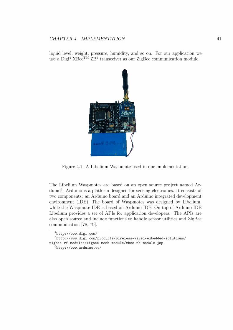
CHAPTER 4. IMPLEMENTATION 41
liquid level, weight, pressure, humidity, and so on. For our application weuse a Digi4 XBeeTM ZB5 transceiver as our ZigBee communication module.
Figure 4.1: A Libelium Waspmote used in our implementation.
The Libelium Waspmotes are based on an open source project named Ar-duino6. Arduino is a platform designed for sensing electronics. It consists oftwo components: an Arduino board and an Arduino integrated developmentenvironment (IDE). The board of Waspmotes was designed by Libelium,while the Waspmote IDE is based on Arduino IDE. On top of Arduino IDELibelium provides a set of APIs for application developers. The APIs arealso open source and include functions to handle sensor utilities and ZigBeecommunication [78, 79].
4http://www.digi.com/5http://www.digi.com/products/wireless-wired-embedded-solutions/
zigbee-rf-modules/zigbee-mesh-module/xbee-zb-module.jsp6http://www.arduino.cc/

CHAPTER 4. IMPLEMENTATION 42
4.1.2 Proxy and Wide Area Nodes
The proxy nodes are implemented with Gumstix7 OveroTM Earth computer-on-module8 developing board. It ships with an ARM CortexTM A8 CPU(OMAP3503 applications processor9 from Texas Instruments10), with a clockrate of 600 MHz. It has 256MB of RAM and 256MB of flash memory. Inaddition, Overo Earth supports other extension boards. For example, Gum-stix Tobi11 can be mounted to Overo Earth and it provides support of digitalvisual interface (DVI) display, Ethernet, USB console, stereo audio, and soon. The OS on Overo Earth is a Linux distribution using opkg12 packagemanagement system. We use cacao13 Java virtual machine in order to runJava applications. The 3G data communication is provided by a 3G USB
Figure 4.2: The hardware of the proxy prototype, where a Libelium Wasp-mote Gateway and a 3G dongle are connected to a Gumstix Overo Earththrough a USB hub.
7http://www.gumstix.com/8http://www.gumstix.com/store/product_info.php?products_id=2119http://focus.ti.com/docs/prod/folders/print/omap3503.html
10http://www.ti.com/11http://www.gumstix.com/store/product_info.php?products_id=23012http://wiki.openmoko.org/wiki/Opkg13http://www.cacaovm.org/
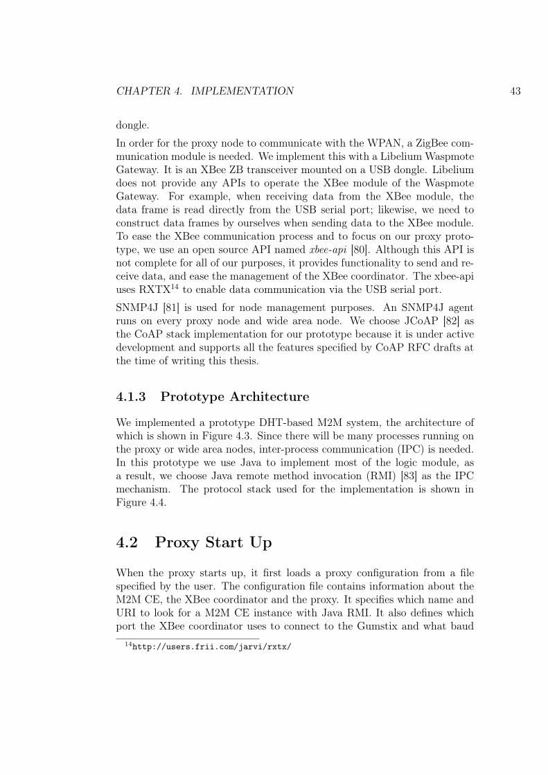
CHAPTER 4. IMPLEMENTATION 43
dongle.
In order for the proxy node to communicate with the WPAN, a ZigBee com-munication module is needed. We implement this with a Libelium WaspmoteGateway. It is an XBee ZB transceiver mounted on a USB dongle. Libeliumdoes not provide any APIs to operate the XBee module of the WaspmoteGateway. For example, when receiving data from the XBee module, thedata frame is read directly from the USB serial port; likewise, we need toconstruct data frames by ourselves when sending data to the XBee module.To ease the XBee communication process and to focus on our proxy proto-type, we use an open source API named xbee-api [80]. Although this API isnot complete for all of our purposes, it provides functionality to send and re-ceive data, and ease the management of the XBee coordinator. The xbee-apiuses RXTX14 to enable data communication via the USB serial port.
SNMP4J [81] is used for node management purposes. An SNMP4J agentruns on every proxy node and wide area node. We choose JCoAP [82] asthe CoAP stack implementation for our prototype because it is under activedevelopment and supports all the features specified by CoAP RFC drafts atthe time of writing this thesis.
4.1.3 Prototype Architecture
We implemented a prototype DHT-based M2M system, the architecture ofwhich is shown in Figure 4.3. Since there will be many processes running onthe proxy or wide area nodes, inter-process communication (IPC) is needed.In this prototype we use Java to implement most of the logic module, asa result, we choose Java remote method invocation (RMI) [83] as the IPCmechanism. The protocol stack used for the implementation is shown inFigure 4.4.
4.2 Proxy Start Up
When the proxy starts up, it first loads a proxy configuration from a filespecified by the user. The configuration file contains information about theM2M CE, the XBee coordinator and the proxy. It specifies which name andURI to look for a M2M CE instance with Java RMI. It also defines whichport the XBee coordinator uses to connect to the Gumstix and what baud
14http://users.frii.com/jarvi/rxtx/

CHAPTER 4. IMPLEMENTATION 44
Figure 4.3: A prototype of the DHT-based M2M system, where a proxy isused to make WPAN nodes globally addressable and accessible from a 3GWWAN.
IEEE 802.15.4
UDP
SNMP4J
Proxy Logic
IP
Chord
M2M CE
3G / GSM
JCoAP
XBee
xbee-api
Management Module
Proxy Node
Figure 4.4: A prototype used for our implementation.
rate should be used for serial communication. Finally the configuration filespecifies the CoAP name of the proxy and Java RMI information so that theproxy instance can be called from another application process.
The proxy then gets a handle on the M2M CE instance with Java RMI andjoins the DHT overlay with its name specified in the configuration file. Afterit becomes a part of the overlay it is ready to announce WPAN nodes tothe overlay. In addition, a CoAP server starts listening on a certain port toaccept incoming requests from other proxy peers or WWAN nodes.

CHAPTER 4. IMPLEMENTATION 45
4.3 WPAN Node Joining and Leaving
Initially when the proxy starts up, it allows XBee nodes with correct securityoptions to join the WPAN. Once an XBee node joins, it is announced tothe overlay by the proxy with a predefined CoAP name. This name canbe later configured using SNMP. However, it is not implemented in thisimplementation.
An XBee coordinator checks its network configuration (PAN ID, operatingchannel, stack profile, and security options) after a reset or power cycle. If anyparameter is invalid then the coordinator tries to start up another network,unless the network settings have been written to non-volatile memory. AnXBee end device runs in a similar way as the coordinator, except that ittries to join another network instead of starting another network when theparameters are not valid after a reset or power cycle.
When an XBee coordinator starts up a network and end devices join thenetwork, they will send ZDO “device announcement” messages to the coor-dinator. After the XBee coordinator is reset or power cycled, then the enddevices do not send a “device announcement” to it when they are started.Instead, when many-to-one routing is used in the XBee network they sendthe coordinator a “route record indicator” messages, which carries a distance-vector like information indicating all the nodes the message have passed by.When a “route record indicator” message is received by the coordinator, weconsider an XBee node has (re)joined the network.
4.4 Application Logic
4.4.1 CoAP Message Parsing
When the proxy receives a message it checks the destination of the message.More specifically, a “URI-Host” option defines the destination. If the finaldestination is the proxy, it digests the message itself. On the other hand, ifthe destination is a WPAN node, the proxy then translates the CoAP nameinto ZigBee 64-bit address and relays the message to the corresponding XBeenode.

CHAPTER 4. IMPLEMENTATION 46
4.4.2 Waspmote Application Packet Fragmentation andReassembling
Libelium introduces an application header to deal with fragmentation andreassembly. This header is shown as in Figure 4.5.
Figure 4.5: Waspmote application header.
In this header an application is used in the receiver differentiates differentpackets. When the data to be transferred is longer than the maximum pay-load it has to be fragmented. A fragment number and first fragment indicatorfulfill this purpose. The original sender fills the source type (64-bit MAC, 16-bit network address, or maximum 20-byte node identifier string) and sourceaddress. Finally, the data field carries the actual payload.
On the proxy side xbee-api does not provide any APIs to operate on Wasp-mote application packets. As a result we implemented those functions to sendand receive Waspmote application packets. These functions deal specificallywith fragmentation and assembly of Waspmote application packets.

Chapter 5
Discussions
We have stated in Section 3.3 that principles including power efficiency, in-teroperability, scalability, security, and reliability have affected the proxydesign. Some design choices are results endeavor of conforming to one ormore principles. For instance, the introduction of caching mechanism in thesystem tries to improve both power efficiency and reliability (and potentiallyscalability as well). However, the focus of this thesis project has been sys-tem architecture, design, and prototype implementation. We have confirmedthe basic functionality of the prototype and carried out some preliminaryperformance measurements on this prototype.
In the remaining of this chapter we discuss the functionality and perfor-mance evaluation we have done, what are the aspects that may affect systemperformance, and our thoughts on power sources.
5.1 Functionality Evaluation
We stated in Section 3 that the goal of this thesis project is to make resourceconstrained WPAN devices accessible from a larger network. In our design,sensors/actuators are able to join a WPAN managed by a proxy, which an-nounces them to a DHT-overlay that runs on top of IP. The proxy is able todiscover services available in a sensor/actuator and announce these servicesto the DHT-overlay as well.
Simple applications have been developed to test the functionality of theproxy. For example, we have two sample scenarios shown in Figure 5.1 andFigure 5.2, in which nodes from one WPAN are able to communicate trans-parently with nodes in a WWAN. In Figure 5.1 we have verified a scenario
47

CHAPTER 5. DISCUSSIONS 48
where a Waspmote detects motion and sends a message to a Gumstix nodeconnected to an IP network. Specifically, when the Waspmote is moved orshook, it sends a message “Motion detected” to a Gumstix node (the des-tination is hard-coded at the moment). This message is handled by theWaspmote’s proxy node. The proxy first gets the IP address of the Gumstixnode, then it sends a CoAP message to the IP address.
Send to: actuator1
"Motion detected"
LN Sensor(sensor1)
Proxy M2M CE
getIP(actuator1)
WN Actuator(actuator1)
P2P operations
IP of actuator1
Send to: actuator1
CoAP Message: "Motion detected"
Motion
Figure 5.1: A sample scenario implemented in our prototype, where a localWPAN sensor sends message to a WWAN actuator.
Figure 5.2 describes another scenario where the data flow is from a Gumstixto a Waspmote in a WPAN. Users can specify which WPAN node the Gum-stix should send a message to, using a command line interface (this interfacewill be updated with a button in our following work). This Gumstix thenlooks up the IP of the proxy responsible for the WPAN node and sends aCoAP message to the proxy, specifying which WPAN node is the final desti-nation. Upon receiving the message, the proxy looks up the ZigBee address ofthe Waspmote and sends a ZigBee message to the corresponding Waspmote.The Waspmote blinks its LED lights if the message is “Blink”.
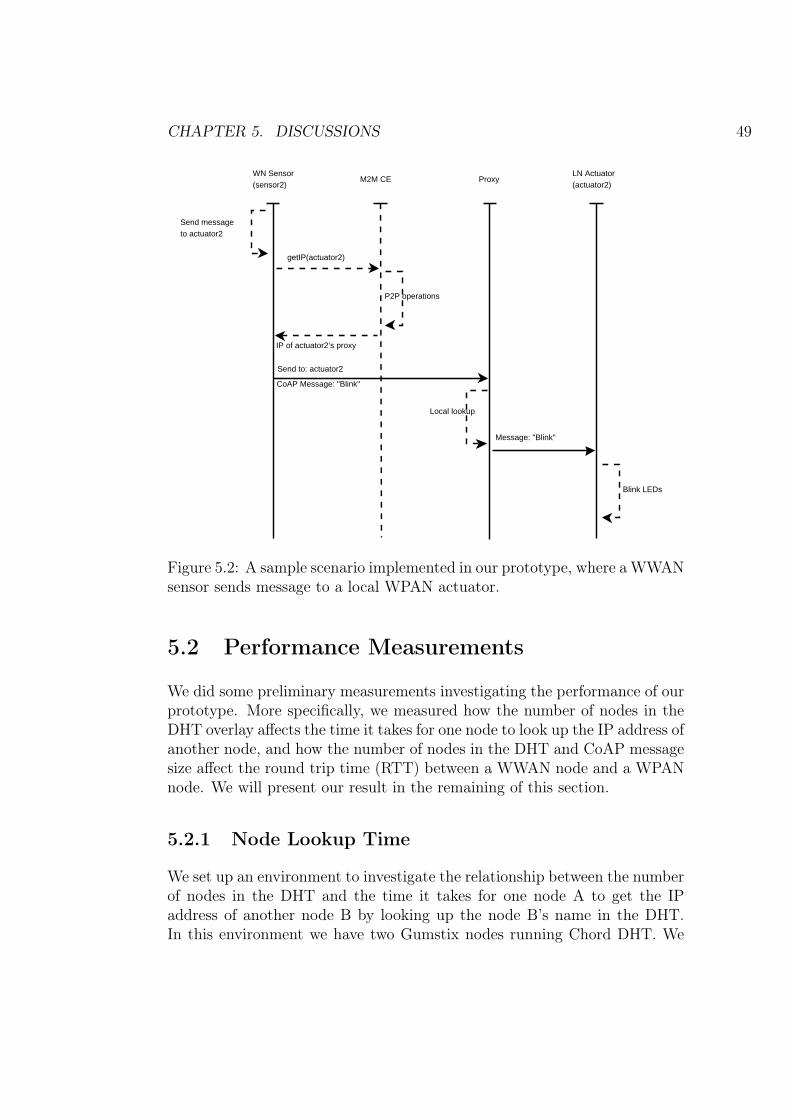
CHAPTER 5. DISCUSSIONS 49
M2M CE
getIP(actuator2)
ProxyLN Actuator(actuator2)
P2P operations
IP of actuator2’s proxy
Send to: actuator2
CoAP Message: "Blink"
Local lookup
Message: "Blink"
WN Sensor(sensor2)
Send messageto actuator2
Blink LEDs
Figure 5.2: A sample scenario implemented in our prototype, where a WWANsensor sends message to a local WPAN actuator.
5.2 Performance Measurements
We did some preliminary measurements investigating the performance of ourprototype. More specifically, we measured how the number of nodes in theDHT overlay affects the time it takes for one node to look up the IP address ofanother node, and how the number of nodes in the DHT and CoAP messagesize affect the round trip time (RTT) between a WWAN node and a WPANnode. We will present our result in the remaining of this section.
5.2.1 Node Lookup Time
We set up an environment to investigate the relationship between the numberof nodes in the DHT and the time it takes for one node A to get the IPaddress of another node B by looking up the node B’s name in the DHT.In this environment we have two Gumstix nodes running Chord DHT. We

CHAPTER 5. DISCUSSIONS 50
have a personal computer (PC) in the same network as those two Gumstixnodes. The connection was Ethernet instead of 3G, since our operator hasblocked most of the ports we needed to run DHT algorithms (when we aredoing the evaluation). On this PC a number of virtual nodes are started.For the first measurement there are 8 virtual DHT nodes running on thePC, and 18 virtual nodes in the second measurement, 28 virtual nodes in thethird measurement, and so forth. We look up the IP address of Gumstix Afrom Gumstix node B and note down the time this process takes. Finally weplotted a figure showing how the number of DHT nodes affects node lookuptime, as shown in Figure 5.3.
0
1000
2000
3000
4000
5000
6000
0 10 20 30 40 50 60 70
Tim
e (m
s) o
f loo
king
up
the
IP a
ddre
ss o
f a n
ode
Number of nodes in DHT
Figure 5.3: The number of nodes in the DHT does not significantly affectnode lookup time, but he stability of node looking up decreases as the numberof DHT nodes increases.
We can see from Figure 5.3 that the both the average and medium lookuptime is around 200 milliseconds when there are no more than 30 nodes in theDHT. Almost all lookups were successful within 300 milliseconds. However,as the number of DHT nodes increases to 40, the average lookup time remainslow, while the medium lookup time increases significantly because of one peekvalue in one case where the lookup takes more than 5000 milliseconds. This

CHAPTER 5. DISCUSSIONS 51
abnormality might have been caused by busy process scheduling on the PCon which the virtual DHT nodes run. Similarly, when the number of DHTnodes increases to 50, another peek value is found. When the number of DHTnodes increases to 60, the average lookup time increases not so much, but themedium lookup time increases much and the variations are large comparedwith the testing case where there are no more than 30 DHT nodes. Webelieve these phenomena are caused by the depletion of resources (CPU slotsand memory) on the PC running virtual DHT nodes. In fact, when we had58 virtual nodes running on a single PC, it was too busy running the virtualnodes to response to external user input, for example, keyboard interruptions.From this observation we feel that the node lookup time is low enough inmost cases, when the number of DHT nodes is small. Further measurementsneed to be carried out with the actual network factors involving into the testcases, for example, by running a number of virtual DHT nodes on differentPCs placed in a network.
5.2.2 RTT between WWAN and WPAN Nodes
Next we measure the RTT between a WWAN node and a WPAN node,using the same environment as we did in the previous sub-section. This timewe still simulate virtual DHT nodes on a PC, and try to investigate howthe number of DHT nodes and CoAP message size affect the RTT from aGumstix node to a Waspmote. We generate random character strings withsize from 1 to 180 bytes and note down the time the messages travel fromthe Gumstix to the Waspmote and then get back to the original Gumstixnode. We have plotted the collected data in Figure 5.4.
From Figure 5.4 we see that RTT is not significantly affected by the numberof nodes in the DHT, as the curves show similar behaviors whether there are10 or 60 DHT nodes. It should not be a surprise since the measured RTT doesnot include node IP lookup time. Furthermore, the DHT nodes are mostlyvirtual nodes and therefore the number of nodes does not significantly influ-ence traffic volume in the network. Note that some messages larger than 150bytes yield exceptionally long RTT. It happens with scenarios where 10, 20,or 30 DHT nodes participate in the network. This happens because of someCoAP message timeout and retransmissions (see the following discussions).
We have two test cases in which the RTT between two WWAN nodes ismeasured. Specifically, we noted down the time it takes for CoAP messages totravel from one Gumstix to another Gumstix proxy node in the same networkand then get back to the original Gumstix. This is done by letting the

CHAPTER 5. DISCUSSIONS 52
0
500
1000
1500
2000
2500
3000
0 20 40 60 80 100 120 140 160 180
RT
T (
ms)
bet
wee
n a
WW
AN
nod
e an
d a
WP
AN
nod
e
CoAP message size (bytes)
10 DHT nodes 20 DHT nodes 30 DHT nodes 40 DHT nodes 50 DHT nodes 60 DHT nodes
Figure 5.4: RTT is affected more significantly by the size of CoAP messagesrather than the number of DHT nodes, when the majority of DHT nodes arevirtual nodes residing on a single PC.
Gumstix proxy to reply with the same CoAP message it receives if messagesare larger than 180 bytes, without sending the message to a WPAN node.That is, CoAP messages no more than 180 bytes are delivered to WPANnodes (results have been plotted in Figure 5.4) but larger messages are simplyreturned to the sender. The measured data is plotted in Figure 5.5. Wenotice from Figure 5.5 that one CoAP message yields a RTT of almost 650milliseconds. However, if we leave this abnormality out, the medium RTTfor both test cases is around 350 milliseconds and the average RTT is around300 milliseconds. Another phenomenon we can see from Figure 5.5 is thatCoAP message size does not seem to have a significant impact on the RTT(when the CoAP messages are between 180 and 300 bytes). Although we donot have any measured data on how it goes with CoAP messages less than180 bytes, we believe it is safe to assume that the medium RTT between twoWWAN nodes will be around 350 milliseconds and the average RTT will bearound 300 milliseconds, assuming no CoAP messages time out or need tobe retransmitted.

CHAPTER 5. DISCUSSIONS 53
200
250
300
350
400
450
500
550
600
650
700
180 200 220 240 260 280 300
RT
T (
ms)
bet
wee
n tw
o W
WA
N n
odes
CoAP message size (bytes)
Test case one Test case two
Figure 5.5: RTT between two WWAN nodes is not significantly influencedby CoAP message size, when CoAP messages are between 180 and 300 bytes.
Since those curves in Figure 5.4 are so similar with each other, now wewill just analyze one curve (see Figure 5.6), which shows the relationshipbetween the size of CoAP messages and RTT, when there are 50 nodes in theDHT. The RTT is quite large when the Gumstix is sending one-byte CoAPmessages. This is probably caused by the fact that neither the Gumstixsender or the receiving proxy node has fully loaded the relevant applicationsin their cache memory. After that the RTT does not change drastically untilthe CoAP message size reaches 62 bytes, where the RTT almost doubled.This is because the proxy has to fragment any messages larger than 61 bytes.The maximum Waspmotes message payload that may fit into one packet is61 bytes in our prototype. Similarly, when the CoAP message size reaches123 bytes, the RTT again goes onto another higher stage, since the maximumpayload for the second (and following) fragments is 62 (rather than 61) bytes.We can also see from the curve that messages divided into the same numberof fragments have similar RTT.
From the above discussions we may conclude the size of CoAP messages doesnot play an important role in affecting the RTT between two WWAN nodes,
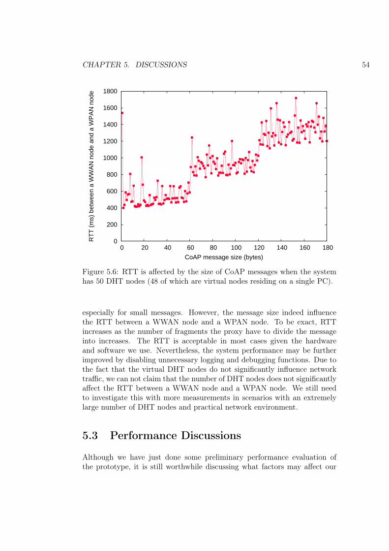
CHAPTER 5. DISCUSSIONS 54
0
200
400
600
800
1000
1200
1400
1600
1800
0 20 40 60 80 100 120 140 160 180
RT
T (
ms)
bet
wee
n a
WW
AN
nod
e an
d a
WP
AN
nod
e
CoAP message size (bytes)
Figure 5.6: RTT is affected by the size of CoAP messages when the systemhas 50 DHT nodes (48 of which are virtual nodes residing on a single PC).
especially for small messages. However, the message size indeed influencethe RTT between a WWAN node and a WPAN node. To be exact, RTTincreases as the number of fragments the proxy have to divide the messageinto increases. The RTT is acceptable in most cases given the hardwareand software we use. Nevertheless, the system performance may be furtherimproved by disabling unnecessary logging and debugging functions. Due tothe fact that the virtual DHT nodes do not significantly influence networktraffic, we can not claim that the number of DHT nodes does not significantlyaffect the RTT between a WWAN node and a WPAN node. We still needto investigate this with more measurements in scenarios with an extremelylarge number of DHT nodes and practical network environment.
5.3 Performance Discussions
Although we have just done some preliminary performance evaluation ofthe prototype, it is still worthwhile discussing what factors may affect our

CHAPTER 5. DISCUSSIONS 55
system’s performance. In this section we specifically discuss in two aspects:proxy throughput and reliability.
5.3.1 Proxy Throughput
DHT-based P2P systems are often thought to be scalable. However, theuse of DHT in our system does not immediately imply that our system isscalable. The DHT provides scalability in the perspective of connecting alarge number of WWAN nodes to the system. In this section we discusswhat can be the bottlenecks that may hinder scalability of our design. Theproxy in our system are responsible of WPAN management and act as agateway for WPAN nodes. All requests from or to a WPAN are processed bythe proxy. As a result, how fast the proxy can process these requests affectsthe overall performance of the M2M system.
We expect an increase of requests to the proxy as the number of WPAN nodesrelying on that proxy grows. Similarly, when the number of WWAN nodesgrows larger and the communication between WWAN nodes and WPANnodes become more frequent, the proxy should also expect a grow of requests.Ideally, the proxy should be able to process as many requests as possibleand produce low delays. Otherwise the performance of the M2M system isdowngraded when proxy throughput can not match the increase of requests.
In order to increase proxy throughput, we may need to use more advancedhardware for proxies and switch to technologies providing more incoming andoutgoing bandwidth (other than 3G). However, this will obviously increasethe cost of proxies and eventually the cost of the system. An alternative isto introduce more proxies when more WPAN nodes need to join the system.This alternative attacks the problem by slightly shifting the scalability issueof proxies to the DHT.
5.3.2 Proxy Reliability
Since a proxy reflects a single point of failure in our design, caching mech-anisms are introduced so tackle this problem. Caching partly remedies thisproblem at the cost of potentially obsolete data. That is, caching in DHT(see Section 3.5.4.2) may be useful for other nodes to get a data copy col-lected by a WPAN node even if the proxy fails. However, this does not helpwhen WPAN management operations are need on a WPAN when its proxyhas failed.

CHAPTER 5. DISCUSSIONS 56
One way to remedy the above problem is introducing redundancy on prox-ies. Unfortunately in our case this is not feasible since the proxy acts asthe coordinator node, while only one coordinator is allowed for each ZigBeenetwork. Another option is to ensure fast recovery of the proxy. Fast re-covery implies fast detection of proxy failure. Fast failure detection can beimplemented using underlying DHT algorithms. For instance, Chord ensurerobustness in face of node failures; and this mechanism can be used for nodefailure detection. Once node failure is detected, alarm messages can be sentto (predefined or dynamically configured) administrators. Then it should beeasier to diagnose what has failed and bring up the node again.
5.4 Power Source
In our design the proxies are supposed to be mains powered. It may bedesirable to have battery powered proxies in some scenarios, for examplewhere no electric sockets are available. In such cases renewable energy sourcesmay come to help. For example, we can use solar panel batteries to providepower the proxies.
The WPAN sensors are expected to last. Generally speaking, these sensorare in sleeping mode most of the time in order to save energy. For sensorsthat may consume much energy, we can consider using wireless chargingtechnologies [84], which is a quickly emerging and promising technology.

Chapter 6
Conclusions and Future Work
This study was a part of the Devices and Interoperability EcosysteM (DIEM)program1 sponsored by the Finnish Funding Agency for Technology and In-novation (TEKES)2 as well as other industrial and research parties. Thestudy at NomadicLab of Ericsson Finland focuses on finding a solution tomove the intelligence of an M2M system from a centralized server to the net-work edge. We proposed a DHT-based M2M system to fulfill this purpose.This project has been further divided into three master’s thesis topics: onetopic focuses on system management applications; one focuses on distributedintelligence; and finally this thesis study focuses on the network edge, i.e.,the proxy and end WPAN nodes. We close this thesis with what we havedone in this thesis project, our conclusions, and what future work is needed.
6.1 Summary
We have done a study on DHT-based M2M networks in this thesis project.More specifically, we focused on the network edge and introduced a proxy insuch networks. We discussed why proxies are necessary for these systems andwhy those efforts are essential. We have kept in mind principles includingpower efficiency, interoperability, scalability, security, and reliability duringthis study. Based on these principles, we proposed our design of the proxy,implemented a prototype, and finally analyzed our design and implementa-tion.
A proxy is necessary since WPAN nodes can not run P2P algorithms due to1http://www.diem.fi/programme2http://www.tekes.fi/en/
57

CHAPTER 6. CONCLUSIONS AND FUTURE WORK 58
resource constraints. In addition, proxies are good for data management andsecurity. They also simplify application logic on WSN nodes and connectheterogeneous WPAN nodes to the M2M system. Although some of theabove functionality may be realized by nodes other than a proxy, they arelikely to add complexity to the whole system. As a result, a proxy can bea good tradeoff to keep the WPAN node logic simple and at the same timeavoid complicating the M2M system too much.
The design of our proxy mainly focuses on WPAN node management and ser-vice management. The proxy acts as both the coordinator and data collectorof the WPAN. It is responsible for configuring the WPAN and allows or dis-allows new WPAN devices joining the network. In our design node joining isdone by applying security options as an access control mechanism, i.e., onlynodes with the same shared security keys as the proxy may join the WPAN.After one node has joined a WPAN, it may voluntarily or involuntarily leavethe network. When a node voluntarily leaves, it may either inform the proxyor not. The proxy provides mechanisms to detect whether a node has leftthe WPAN. The proxy is also responsible for discovering available servicesone WPAN provides. This is dependent on the underlying WPAN protocols,for example, in CoAP resource discovery can be used and in ZigBee ZDO isour choice.
Caching mechanisms have been introduced in order to provide better per-formance. One proxy can cache data both for WPAN nodes and in DHT.Caching for WPAN nodes saves the efforts of querying the WPAN all thetime; caching in DHT improves system reliability. Security has also been aconcern in the proxy design. The secure communication between a proxy andits WWAN peers takes advantage of security mechanisms specified either byCoAP or SNMP; and the secure communication between the WPAN nodesis ensure by WPAN protocols (for example ZigBee security specifications).
Based on our design, a prototype proxy was implemented using Gumstixboards and Waspmote sensor nodes. The implementation took advantageof inexpensive hardware and free/open source software in order to keep thecost low. We have confirmed the basic functionality of the prototype andmade some discussions regarding the design and the prototype. The focusof this thesis project has been system architecture, design, and prototypeimplementation, while not so much performance evaluation has been con-ducted. However, a few preliminary performance measurements have beencarried out. We believe that it should be feasible to use our prototype inpractical scenarios.

CHAPTER 6. CONCLUSIONS AND FUTURE WORK 59
6.2 Future Work
Since no performance evaluation has been done in this thesis work, this shouldbe carried out in the following study. Specifically, the evaluation should fo-cus on power consumption of WPAN nodes, delays the proxy introduces,proxy throughput, comparison of proxy with and without caching mecha-nisms, and system scalability. Although ZigBee devices are designed to lastseveral months or even years with batteries, different applications may havedifferent battery lifetime. Further investigations are needed in order to pro-vide concrete evidence on which application scenarios are appropriate. Theproxy’s performance should be further measured from the perspective of de-lay and throughput, since these factors affect system’s performance as wellas scalability.
Our design mainly uses ZigBee as the WPAN protocol. In the future moreWPAN protocols should be included in the system, for example, 6LoWPAN,Z-Wave, Bluetooth, and so on. When we think about IoT or M2M, devicesin either system are heterogeneous. Various protocols have been developedfor different purposes. However, devices running on top of these protocolscan be integrated into one system by making the proxy support them. Oneproxy node may not support different protocols at the same time since itmay add complexity to the proxy logic. However, proxies supporting dif-ferent underlying WPAN protocols will easily embrace different devices andapplication scenarios into one system, making the system truly intelligentand more ubiquitous.

References
[1] INFSO D.4 Networked Enterprise & RFID INFSO G.2 Micro &Nanosystems in cooperation with the Working Group RFID of the ETPEPOSS, “Internet of Things in 2020: Roadmap for the Future,” May2008. Version 1.1, http://www.iot-visitthefuture.eu/fileadmin/documents/researchforeurope/270808_IoT_in_2020_Workshop_Report_V1-1.pdf.
[2] L. Atzori, A. Iera, and G. Morabito, “The Internet of Things: A survey,”Computer Networks, vol. 54, pp. 2787–2805, October 2010.
[3] S. E. Sarma, S. A. Weis, and D. W. Engels, “RFID Systems and Securityand Privacy Implications,” in In Workshop on Cryptographic Hardwareand Embedded Systems, pp. 454–470, Springer, 2002.
[4] J. Conti, “The Internet of Things,” Communications Engineer, vol. 4,pp. 20 –25, December – January 2006.
[5] A. Walter-Krisch, “Heading towards 50 billion connections.”Ericsson OSS/BSS: http://www.ericsson.com/campaign/opportunitysupportsystems/newsfeed/posts/15/. Accessed Febru-ary 14, 2011.
[6] B. Mellor, “A world of connections,” The Economist, April 2007.
[7] G. Lawton, “Machine-to-machine technology gears up for growth,” Com-puter, vol. 37, pp. 12 – 15, September 2004.
[8] S. Gupta and A. Hirdesh, “Overview of M2M.” Ankit Hird-esh Papers website: http://hriday.ankit.googlepages.com/M2M_overview_paper.pdf. Accessed February 16, 2011.
[9] I. Brezeanu and G. Gorghiu, “Machine to machine applications in enter-prise a new step to intelligent internet control,” in Proceedings of the 1st
60
REFERENCES 61
Workshop on Energy, Transport and Environment Control Applications(ETECA’09), (Targoviste, Romania), pp. 30–45, May 2009.
[10] G. Privat, “From Smart Devices to Ambient Communication.” Work-shop “From RFID to the Internet of Things”. Brussels, Belgium, March2006.
[11] I. F. Akyildiz, W. Su, Y. Sankarasubramaniam, and E. Cayirci, “Asurvey on sensor networks,” IEEE Communications Magazine, vol. 40,pp. 102–114, August 2002.
[12] J. Edgar H. Callaway, Wireless Sensor Networks: Architectures and Pro-tocols. AUERBACH, August 2003.
[13] E. M. Royer and C.-K. Toh, “A Review of Current Routing Protocols forAd-Hoc Mobile Wireless Networks,” IEEE Personal Communications,vol. 6, pp. 46–55, 1999.
[14] L. Song and D. Hatzinakos, “Architecture of Wireless Sensor NetworksWith Mobile Sinks: Sparsely Deployed Sensors,” IEEE Transactions onVehicular Technology, vol. 56, pp. 1826–1836, 2007.
[15] K. Akkaya and M. Younis, “A survey on routing protocols for wirelesssensor networks,” Ad Hoc Networks, vol. 3, pp. 325–349, 2005.
[16] S. M. Hedetniemi, S. T. Hedetniemi, and A. L. Liestman, “A surveyof gossiping and broadcasting in communication networks,” Networks,vol. 18, no. 4, pp. 319–349, 1988.
[17] W. R. Heinzelman, J. Kulik, and H. Balakrishnan, “Adaptive proto-cols for information dissemination in wireless sensor networks,” in Pro-ceedings of the 5th annual ACM/IEEE international conference on Mo-bile computing and networking, MobiCom ’99, (New York, NY, USA),pp. 174–185, ACM, 1999.
[18] C. Intanagonwiwat, R. Govindan, and D. Estrin, “Directed diffusion: ascalable and robust communication paradigm for sensor networks,” inProceedings of the 6th annual international conference on Mobile com-puting and networking, MobiCom ’00, (New York, NY, USA), pp. 56–67,ACM, 2000.
[19] W. Heinzelman, A. Chandrakasan, and H. Balakrishnan, “Energy-efficient communication protocol for wireless microsensor networks,” inSystem Sciences, 2000. Proceedings of the 33rd Annual Hawaii Interna-tional Conference on, p. 10 pp. vol.2, January 2000.

REFERENCES 62
[20] S. Lindsey and C. Raghavendra, “Pegasis: Power-efficient gathering insensor information systems,” in Aerospace Conference Proceedings, 2002.IEEE, vol. 3, pp. 1125 – 1130, 2002.
[21] A. Manjeshwar and D. Agrawal, “Teen: a routing protocol for enhancedefficiency in wireless sensor networks,” in Parallel and Distributed Pro-cessing Symposium., Proceedings 15th International, pp. 2009 – 2015,April 2001.
[22] V. Rodoplu and T. Meng, “Minimum energy mobile wireless networks,”Selected Areas in Communications, IEEE Journal on, vol. 17, pp. 1333– 1344, August 1999.
[23] L. Li and J. Halpern, “Minimum-energy mobile wireless networks revis-ited,” in Communications, 2001. ICC 2001. IEEE International Confer-ence on, vol. 1, pp. 278 –283, June 2001.
[24] Y. Xu, J. Heidemann, and D. Estrin, “Geography-informed energy con-servation for ad hoc routing,” in Proceedings of the 7th annual interna-tional conference on Mobile computing and networking, MobiCom ’01,(New York, NY, USA), pp. 70–84, ACM, 2001.
[25] Y. Yu, R. Govindan, and D. Estrin, “Geographical and energy awarerouting: a recursive data dissemination protocol for wireless sensor net-works,” tech. rep., UCLA Computer Science Department, 2001.
[26] J.-H. Chang and L. Tassiulas, “Maximum lifetime routing in wireless sen-sor networks,” IEEE/ACM Trans. Netw., vol. 12, pp. 609–619, August2004.
[27] K. Kalpakis, K. Dasgupta, and P. Namjoshi, “Maximum lifetime datagathering and aggregation in wireless sensor networks,” Networks TheProceedings of the Joint International Conference on Wireless LANs andHome Networks ICWLHN 2002 and Networking ICN 2002, pp. 685–696,2002.
[28] K. Sohrabi, J. Gao, V. Ailawadhi, and G. J. Pottie, “Protocols for self-organization of a wireless sensor network,” IEEE Personal Communica-tions, vol. 7, pp. 16–27, 2000.
[29] J. A. Gutiérrez, E. H. Callaway, and R. L. Barrett, Low-Rate Wire-less Personal Area Networks: Enabling Wireless Sensors with IEEE802.15.4. IEEE Standards, USA: Standards Information Network -IEEE Press, 1. ed., 2003.

REFERENCES 63
[30] LAN/MAN Standards Committee of the IEEE Computer Society, Wire-less Medium Access Control (MAC) and Physical Layer (PHY) Speci-fications for Low-Rate Wireless Personal Area Networks (LR-WPANs).New York, USA: IEEE, IEEE Std 802.15.4-2006 ed., 2006.
[31] LAN/MAN Standards Committee of the IEEE Computer Society, Wire-less Medium Access Control (MAC) and Physical Layer (PHY) Speci-fications for Low-Rate Wireless Personal Area Networks (LR-WPANs).New York, USA: IEEE, IEEE Std 802.15.4-2003 ed., 2003.
[32] H. Zimmermann, “Innovations in Internetworking,” ch. OSI referencemodel – The ISO model of architecture for open systems interconnection,pp. 2–9, Norwood, MA, USA: Artech House, Inc., 1988.
[33] S. C. Ergen, “ZigBee/IEEE 802.15.4 Summary,” September 2004. http://pages.cs.wisc.edu/~suman/courses/838/papers/zigbee.pdf.Accessed March 12, 2011.
[34] ZigBee Alliance, “The Alliance,” http://www.zigbee.org/About/AboutAlliance/TheAlliance.aspx. Accessed April 4, 2011.
[35] A. Elahi and A. Gschwender, ZigBee Wireless Sensor and Control Net-work. Prentice Hall Communications Engineering and Emerging Tech-nologies Series, Prentice Hall, 2009.
[36] ZigBee Standards Organization, ZigBee Specification, Docu-ment 053474r17. California, USA: http://www.zigbee.org/Specifications.aspx, January 2008.
[37] N. Kushalnagar, G. Montenegro, and C. Schumacher, “IPv6 over Low-Power Wireless Personal Area Networks (6LoWPANs): Overview, As-sumptions, Problem Statement, and Goals,” RFC 4919, Internet Engi-neering Task Force, August 2007.
[38] S. Deering and R. Hinden, “Internet protocol, version 6 (IPv6) specifi-cation,” RFC 2460, Internet Engineering Task Force, December 1998.
[39] G. Montenegro, N. Kushalnagar, J. Hui, and D. Culler, “Transmissionof IPv6 Packets over IEEE 802.15.4 Networks,” RFC 4944, Internet En-gineering Task Force, September 2007.
[40] Z. Shelby, K. Hartke, C. Bormann, and B. Frank, “Constrained Ap-plication Protocol (CoAP), work in progress,” draft-ietf-core-coap-05,Internet Engineering Task Force, 2011.

REFERENCES 64
[41] R. T. Fielding, Architectural Styles and the Design of Network-basedSoftware Architectures. PhD thesis, University of California, Irvine,Irvine, California, 2000.
[42] R. Fielding, J. Gettys, J. Mogul, H. Frystyk, L. Masinter, P. Leach, andT. Berners-Lee, “Hypertext transfer protocol – HTTP/1.1,” RFC 2616,Internet Engineering Task Force, June 1999.
[43] Z. Shelby, “CoRE Link Format, work in progress,” draft-ietf-core-link-format-03, Internet Engineering Task Force, 2011.
[44] G. S. Manku, Dipsea: a modular distributed hash table. PhD thesis,Stanford University, August 2004.
[45] M. Naor and U. Wieder, “Novel Architectures for P2P Applications:the Continuous-Discrete Approach,” ACM TRANSACTIONS ON AL-GORITHMS, vol. 3, no. 3, pp. 50–59, 2007.
[46] H. Balakrishnan, M. F. Kaashoek, D. Karger, R. Morris, and I. Sto-ica, “Looking up data in P2P systems,” Communications of the ACM,vol. 46, pp. 43–48, February 2003.
[47] R. Rivest, “The MD5 Message-Digest algorithm,” RFC 1321, InternetEngineering Task Force, April 1992.
[48] R. Oppliger, SSL and TLS: Theory and Practice. Norwood, MA, USA:Artech House, Inc., 2009.
[49] S. Kent and K. Seo, “Security Architecture for the Internet Protocol,”RFC 4301, Internet Engineering Task Force, December 2009.
[50] P. Gutmann and P. Gutmann, “Software generation of practically strongrandom numbers,” in In Proceedings of the 8th USENIX Security Sym-posium, pp. 243–257, 1998.
[51] D. Karger, E. Lehman, T. Leighton, R. Panigrahy, M. Levine, andD. Lewin, “Consistent hashing and random trees: distributed cachingprotocols for relieving hot spots on the World Wide Web,” in Proceedingsof the twenty-ninth annual ACM symposium on Theory of computing,STOC ’97, (New York, NY, USA), pp. 654–663, ACM, 1997.
[52] T. White, “Consistent hashing,” http://www.lexemetech.com/2007/11/consistent-hashing.html. Accessed February 21, 2011.

REFERENCES 65
[53] I. Stoica, R. Morris, D. Karger, M. F. Kaashoek, and H. Balakrish-nan, “Chord: A scalable peer-to-peer lookup service for internet applica-tions,” in Proceedings of the 2001 conference on Applications, technolo-gies, architectures, and protocols for computer communications, SIG-COMM ’01, (New York, NY, USA), pp. 149–160, ACM, 2001.
[54] D. Karger, A. Sherman, A. Berkheimer, B. Bogstad, R. Dhanidina,K. Iwamoto, B. Kim, L. Matkins, and Y. Yerushalmi, “Web caching withconsistent hashing,” Computer Networks, vol. 31, no. 11-16, pp. 1203 –1213, 1999.
[55] W. Peterson and D. Brown, “Cyclic Codes for Error Detection,” Proceed-ings of the Institute of Radio Engineers, vol. 49, pp. 228 –235, January1961.
[56] D. Eastlake and P. Jones, “US secure hash algorithm 1 (SHA1),” RFC3174, Internet Engineering Task Force, September 2001.
[57] F. Dabek, E. Brunskill, M. F. Kaashoek, D. Karger, R. Morris, I. Sto-ica, and H. Balakrishnan, “Building peer-to-peer systems with chord, adistributed lookup service,” in Proceedings of the 8th IEEE Workshopon Hot Topics in Operating Systems (HotOS-VIII), pp. 71–76, 2001.
[58] J. Hautakorpi and G. Camarillo, “Evaluation of DHTs from the view-point of interpersonal communications,” in Proceedings of the 6th in-ternational conference on Mobile and ubiquitous multimedia, MUM ’07,(New York, NY, USA), pp. 74–83, ACM, 2007.
[59] J. Case, M. Fedor, M. Schoffstall, and C. Davin, “Simple network man-agement protocol (SNMP),” RFC 1157, Internet Engineering Task Force,May 1990.
[60] D. Harrington, R. Presuhn, and B. Wijnen, “An architecture for describ-ing simple network management protocol (SNMP) management frame-works,” RFC 3411, Internet Engineering Task Force, December 2002.
[61] J. Case, K. McCloghrie, M. Rose, and S. Waldbusser, “Protocol oper-ations for version 2 of the simple network management protocol (SN-MPv2),” RFC 1905, Internet Engineering Task Force, Januaray 1996.
[62] J. Mäenpää and J. J. Bolonio, “Performance of resource location anddiscovery (reload) on mobile phones,” in Wireless Communications andNetworking Conference (WCNC), 2010 IEEE, pp. 1 – 6, April 2010.
REFERENCES 66
[63] C. Jennings, B. B. Lowekamp, E. Rescorla, S. A. Baset, andH. Schulzrinne, “REsource LOcation And Discovery (RELOAD) BaseProtocol, work in progress,” draft-ietf-p2psip-base-15, Internet Engi-neering Task Force, May 2011.
[64] S. W. Ambler, The Object Primer : Agile Model-Driven Developmentwith UML 2.0. Cambridge University Press, 2004.
[65] Digi International, “XBee R© /XBee-PRO R© ZB RF Modules,” November2010. http://ftp1.digi.com/support/documentation/90000976_G.pdf. Accessed April 26, 2011.
[66] Libelium Comunicaciones Distribuidas S.L., “Over the Air Program-ming with 802.15.4 and ZigBee: Laying the groundwork,” May2011. http://www.libelium.com/documentation/waspmote/over_the_air_programming.pdf. Accessed June 16, 2011.
[67] B. M. Hauzeur, “A model for naming, addressing and routing,” ACMTransactions on Information Systems (TOIS), vol. 4, pp. 293–311, De-cember 1986.
[68] C. Perkins, E. Belding-Royer, and S. Das, “Ad hoc On-Demand distancevector (AODV) routing,” RFC 3561, Internet Engineering Task Force,July 2003.
[69] C. Frank, V. Handziski, and H. Karl, “Service discovery in wireless sensornetworks,” tech. rep., Technical University Berlin, 2004.
[70] M. Botts and A. Robin, “SensorML.” http://www.ogcnetwork.net/SensorML. Accessed June 19, 2011.
[71] E. Rescorla and N. Modadugu, “Datagram Transport Layer Security,”RFC 4347, Internet Engineering Task Force, April 2006.
[72] K. McCloghrie, “An administrative infrastructure for SNMPv2,” RFC1909, Internet Engineering Task Force, 1996.
[73] G. Waters, “User-based security model for SNMPv2,” RFC 1910, Inter-net Engineering Task Force, 1996.
[74] U. Blumenthal and B. Wijnen, “User-based security model (USM) forversion 3 of the simple network management protocol (SNMPv3),” RFC3414, Internet Engineering Task Force, 2002.

REFERENCES 67
[75] U. Blumenthal, F. Maino, and K. McCloghrie, “The advanced encryp-tion standard (AES) cipher algorithm in the SNMP user-based securitymodel,” RFC 3826, Internet Engineering Task Force, June 2004.
[76] J. S. Reddy, “ZigBee Security,” 2004. http://www.zigbee.org/imwp/idms/popups/pop_download.asp?contentID=9436. Accessed June 12,2011.
[77] Libelium Comunicaciones Distribuidas S.L., “Waspmote Datasheet,”March 2011. http://www.libelium.com/documentation/waspmote/waspmote-datasheet_eng.pdf. Accessed April 26, 2011.
[78] Libelium Comunicaciones Distribuidas S.L., “Waspmote TechnicalGuide,” October 2010. http://www.libelium.com/documentation/waspmote/waspmote-technical_guide_eng.pdf. Accessed April 26,2011.
[79] Libelium Comunicaciones Distribuidas S.L., “Waspmote ZigBeeNetworking Guide,” July 2010. http://www.libelium.com/documentation/waspmote/waspmote-zigbee-networking_guide.pdf. Accessed April 26, 2011.
[80] Google Code Project Home, “xbee-api: A Java API for Digi XBee/XBee-Pro OEM RF Modules.” http://code.google.com/p/xbee-api/. Ac-cessed June 18, 2011.
[81] SNMP4J.org, “The SNMP API for Java.” http://www.snmp4j.org/.Accessed June 18, 2011.
[82] D. Pauli, “Java imlementation of CoAP.” https://github.com/dapaulid/JCoAP. Accessed June 18, 2011.
[83] Oracle, “Remote Method Invocation Home.” http://www.oracle.com/technetwork/java/javase/tech/index-jsp-136424.html. AccessedJune 13, 2011.
[84] D. W. Harrist, “Wireless battery charging system using radio frequencyenergy harvesting,” Master’s thesis, University of Pittsburgh, USA,2004.
[85] Trouble shooting - Rxtx. http://rxtx.qbang.org/wiki/index.php/Trouble_shooting#How_does_rxtx_detect_ports.3F__Can_I_override_it.3F. Accessed June 18, 2011.

REFERENCES 68
[86] Libelium Comunicaciones Distribuidas S.L., “Waspmote Accelerom-eter Programming Guide,” July 2010. http://www.libelium.com/documentation/waspmote/waspmote-accelerometer-programming_guide.pdf. Accessed April 26, 2011.

Appendix A
Implementation Issues
A.1 RXTX Port Scan
RXTX tries scanning all devices in /dev for potential ports by default. Thisprocess takes a long time (around two minutes) on Gumstix. One may restrictthe scanning process in order to speed up the proxy logic [85]. In Java thiscan be done by specifying environment parameters “gnu.io.rxtx.SerialPorts”and “gnu.io.rxtx.ParallelPorts”. For example, in our case we start up theproxy using the following command:
java -cp . \-Djava.security.policy=client.policy \-Dgnu.io.rxtx.SerialPorts=/dev/ttyUSB3 \-jar proxy.jar proxy.config
A.2 Bug in Waspmote API
There is a bug related to security key setting in Waspmote API version 0.15and previous versions. Only the first eight bytes of the key will be used whensetting the network key or link key. The problem lies in function “gen_data()”in lines 4355-4403 of “WaspXBeeCore.cpp” in Waspmote API version 0.15,as listed below.
1 /∗2 Function : Generates the API frame to send to the XBee module3 Parameters :4 data : The s t r i n g t ha t con ta ins par t o f the API frame
69

APPENDIX A. IMPLEMENTATION ISSUES 70
5 param : The param to s e t6 Returns : Nothing7 Values : S tore s in ’command ’ v a r i a b l e the API frame to send to
the XBee module8 ∗/9 void WaspXBeeCore : : gen_data ( const char∗ data , uint8_t∗ param)
10 {11 uint8_t inc =0;12 uint8_t inc2 =0;1314 clearCommand ( ) ;15 i t =0;16 while ( data [ i t ] != ’ \0 ’ ) {17 inc++;18 i t ++;19 }20 inc /=2;2122 while ( inc2<inc ) {23 command [ inc2 ]= Ut i l s . conve r t e r ( data [2∗ inc2 ] , data [2∗ inc2 +1]) ;24 inc2++;25 }2627 i f ( inc >11)28 {29 for ( i t =0; i t <8; i t++)30 {31 command [ inc−9+i t ]=param [ i t ] ;32 }33 }34 else i f ( inc==11)35 {36 for ( i t =0; i t <3; i t++)37 {38 command [ inc−4+i t ]=param [ i t ] ;39 }40 }41 else i f ( inc==10)42 {43 for ( i t =0; i t <2; i t++)44 {45 command [ inc−3+i t ]=param [ i t ] ;46 }47 }48 else command [ inc −2]=param [ 0 ] ;49 }

APPENDIX A. IMPLEMENTATION ISSUES 71
However, this bug has been fixed since Waspmote API version 0.161. Thefixed function “gen_data()” is listed as follows.
1 /∗2 Function : Generates the API frame to send to the XBee module3 Parameters :4 data : The s t r i n g t ha t con ta ins par t o f the API frame5 param : The param to s e t6 Returns : Nothing7 Values : S tore s in ’command ’ v a r i a b l e the API frame to send to
the XBee module8 ∗/9 void WaspXBeeCore : : gen_data ( const char∗ data , uint8_t∗ param)
10 {11 uint8_t inc =0;12 uint8_t inc2 =0;1314 clearCommand ( ) ;15 i t =0;16 while ( data [ i t ] != ’ \0 ’ ) {17 inc++;18 i t ++;19 }20 inc /=2;2122 while ( inc2<inc ) {23 command [ inc2 ]= Ut i l s . conve r t e r ( data [2∗ inc2 ] , data [2∗ inc2
+1]) ;24 inc2++;25 }26 // The f o l l ow i n g l i n e s have been updated .27 i f ( inc==24)28 {29 for ( i t =0; i t <16; i t++)30 {31 command [ inc−17+ i t ]=param [ i t ] ;32 }33 }34 else i f ( inc==16)35 {36 for ( i t =0; i t <8; i t++)37 {38 command [ inc−9+i t ]=param [ i t ] ;39 }40 }41 else i f ( inc==11)42 {
1http://www.libelium.com/downloads/Waspmote_changelog.txt
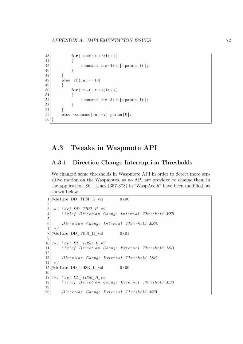
APPENDIX A. IMPLEMENTATION ISSUES 72
43 for ( i t =0; i t <3; i t++)44 {45 command [ inc−4+i t ]=param [ i t ] ;46 }47 }48 else i f ( inc==10)49 {50 for ( i t =0; i t <2; i t++)51 {52 command [ inc−3+i t ]=param [ i t ] ;53 }54 }55 else command [ inc −2]=param [ 0 ] ;56 }
A.3 Tweaks in Waspmote API
A.3.1 Direction Change Interruption Thresholds
We changed some thresholds in Waspmote API in order to detect more sen-sitive motion on the Waspmotes, as no API are provided to change them inthe application [86]. Lines (357-378) in “WaspAcc.h” have been modified, asshown below.
1 #define DD_THSI_L_val 0x0023 /∗ ! \ de f DD_THSI_H_val4 \ b r i e f Direc t ion Change In t e rna l Threshold MSB56 Direc t ion Change In t e rna l Threshold MSB.7 ∗/8 #define DD_THSI_H_val 0x019
10 /∗ ! \ de f DD_THSE_L_val11 \ b r i e f Direc t ion Change Externa l Threshold LSB1213 Direc t ion Change Externa l Threshold LSB.14 ∗/15 #define DD_THSE_L_val 0x001617 /∗ ! \ de f DD_THSE_H_val18 \ b r i e f Direc t ion Change Externa l Threshold MSB1920 Direc t ion Change Externa l Threshold MSB.

APPENDIX A. IMPLEMENTATION ISSUES 73
21 ∗/22 #define DD_THSE_H_val 0x02
The original values are:1 #define DD_THSI_L_val 0x0023 /∗ ! \ de f DD_THSI_H_val4 \ b r i e f Direc t ion Change In t e rna l Threshold MSB56 Direc t ion Change In t e rna l Threshold MSB.7 ∗/8 #define DD_THSI_H_val 0x309
10 /∗ ! \ de f DD_THSE_L_val11 \ b r i e f Direc t ion Change Externa l Threshold LSB1213 Direc t ion Change Externa l Threshold LSB.14 ∗/15 #define DD_THSE_L_val 0x001617 /∗ ! \ de f DD_THSE_H_val18 \ b r i e f Direc t ion Change Externa l Threshold MSB1920 Direc t ion Change Externa l Threshold MSB.21 ∗/22 #define DD_THSE_H_val 0x3C
A.3.2 Maximum Data Length
We changed the length of the maximum data that can be transferred bythe Waspmotes. The original value is 100 bytes, we change it to 300 bytes.This is done by changing the value in line 56 of “WaspXBeeConstants.h” inWaspmote API version 0.18.
1 #define MAX_DATA 300

APPENDIX A. IMPLEMENTATION ISSUES 74
A.4 Waspmote Logic
We simulate two different type of WPAN nodes in our prototype: a motionsensor and an LED actuator. A motion sensor detects its own movement.When it is moved or shook, it sends a message to a destination node (hard-coded at the moment). An LED actuator listens to incoming ZigBee messagesand once it receives a specific command (hard-coded and will be configurablein following work), it blinks its LED lights on board.

www.kth.se
TRITA-ICT-EX-2011:146


![Evolving Hash Functions using Genetic Algorithmsajiips.com.au/papers/V4.1/V4N1.4 - Evolving Hash Functions using... · hash function called "PKP Hash" by Peter.K.Pearson [5] that](https://img.dokumen.tips/doc/110x75/5e3486a76e7276290f0add90/evolving-hash-functions-using-genetic-evolving-hash-functions-using-hash.jpg)