Embed Size (px)
Citation preview
International Journal of Science and Research (IJSR) ISSN (Online): 2319-7064
Impact Factor (2012): 3.358
Volume 3 Issue 11, November 2014 www.ijsr.net
Licensed Under Creative Commons Attribution CC BY
A Programmable Hybrid Solar-Wind Energy System Using Cuk-Sepic Fused Converter Topology
S. Lakshmi Sirisha1, A. Hari Prasad2
1PG Student, PE& ED, VVIT, JNTUK, Andhra Pradesh, India
2Assistant Professor, EEE, VVIT JNTUK, Andhra Pradesh, India
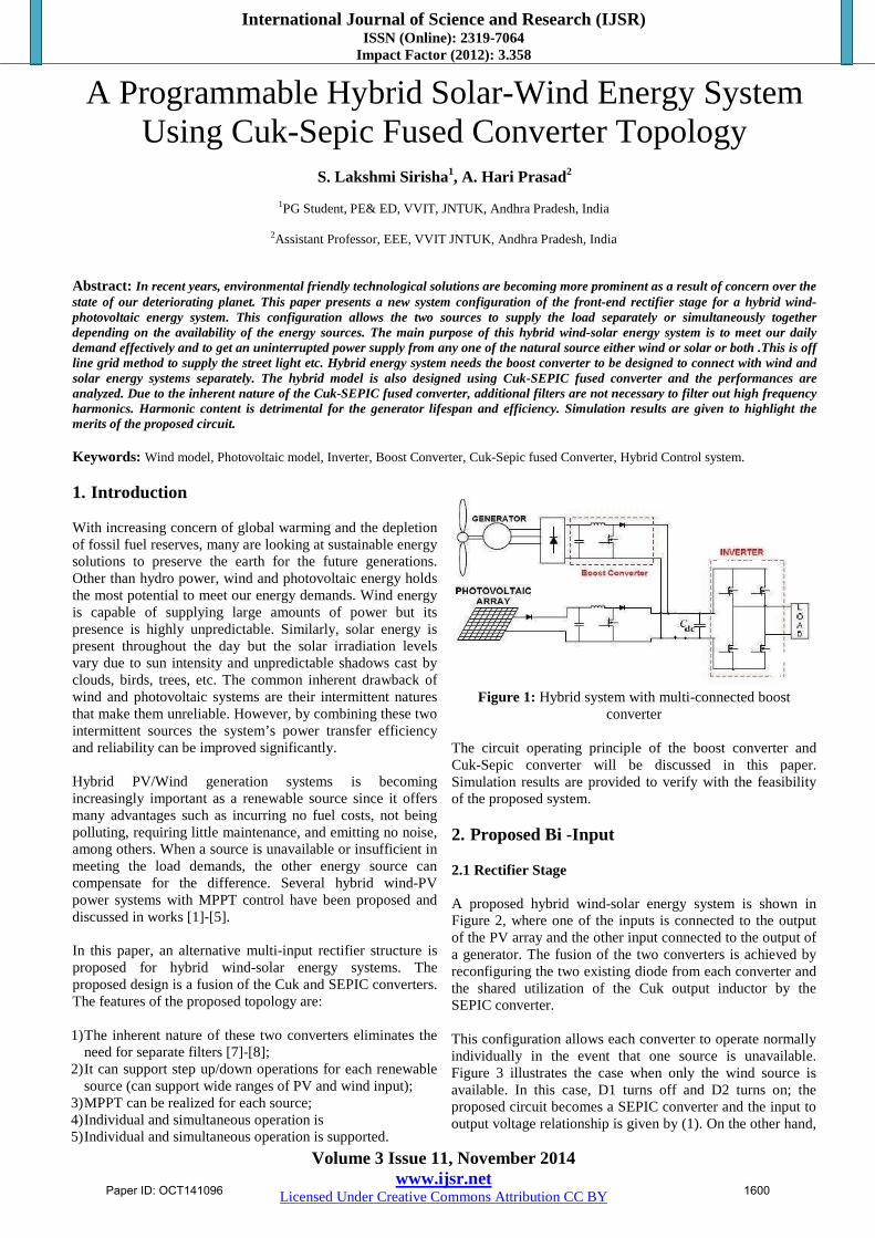
Abstract: In recent years, environmental friendly technological solutions are becoming more prominent as a result of concern over the state of our deteriorating planet. This paper presents a new system configuration of the front-end rectifier stage for a hybrid wind-photovoltaic energy system. This configuration allows the two sources to supply the load separately or simultaneously together depending on the availability of the energy sources. The main purpose of this hybrid wind-solar energy system is to meet our daily demand effectively and to get an uninterrupted power supply from any one of the natural source either wind or solar or both .This is off line grid method to supply the street light etc. Hybrid energy system needs the boost converter to be designed to connect with wind and solar energy systems separately. The hybrid model is also designed using Cuk-SEPIC fused converter and the performances are analyzed. Due to the inherent nature of the Cuk-SEPIC fused converter, additional filters are not necessary to filter out high frequency harmonics. Harmonic content is detrimental for the generator lifespan and efficiency. Simulation results are given to highlight the merits of the proposed circuit. Keywords: Wind model, Photovoltaic model, Inverter, Boost Converter, Cuk-Sepic fused Converter, Hybrid Control system. 1. Introduction With increasing concern of global warming and the depletion of fossil fuel reserves, many are looking at sustainable energy solutions to preserve the earth for the future generations. Other than hydro power, wind and photovoltaic energy holds the most potential to meet our energy demands. Wind energy is capable of supplying large amounts of power but its presence is highly unpredictable. Similarly, solar energy is present throughout the day but the solar irradiation levels vary due to sun intensity and unpredictable shadows cast by clouds, birds, trees, etc. The common inherent drawback of wind and photovoltaic systems are their intermittent natures that make them unreliable. However, by combining these two intermittent sources the system’s power transfer efficiency and reliability can be improved significantly. Hybrid PV/Wind generation systems is becoming increasingly important as a renewable source since it offers many advantages such as incurring no fuel costs, not being polluting, requiring little maintenance, and emitting no noise, among others. When a source is unavailable or insufficient in meeting the load demands, the other energy source can compensate for the difference. Several hybrid wind-PV power systems with MPPT control have been proposed and discussed in works [1]-[5]. In this paper, an alternative multi-input rectifier structure is proposed for hybrid wind-solar energy systems. The proposed design is a fusion of the Cuk and SEPIC converters. The features of the proposed topology are: 1) The inherent nature of these two converters eliminates the
need for separate filters [7]-[8]; 2) It can support step up/down operations for each renewable
source (can support wide ranges of PV and wind input); 3) MPPT can be realized for each source; 4) Individual and simultaneous operation is 5) Individual and simultaneous operation is supported.
Figure 1: Hybrid system with multi-connected boost
converter
The circuit operating principle of the boost converter and Cuk-Sepic converter will be discussed in this paper. Simulation results are provided to verify with the feasibility of the proposed system. 2. Proposed Bi -Input 2.1 Rectifier Stage A proposed hybrid wind-solar energy system is shown in Figure 2, where one of the inputs is connected to the output of the PV array and the other input connected to the output of a generator. The fusion of the two converters is achieved by reconfiguring the two existing diode from each converter and the shared utilization of the Cuk output inductor by the SEPIC converter. This configuration allows each converter to operate normally individually in the event that one source is unavailable. Figure 3 illustrates the case when only the wind source is available. In this case, D1 turns off and D2 turns on; the proposed circuit becomes a SEPIC converter and the input to output voltage relationship is given by (1). On the other hand,
Paper ID: OCT141096 1600

International Journal of Science and Research (IJSR) ISSN (Online): 2319-7064
Impact Factor (2012): 3.358
Volume 3 Issue 11, November 2014 www.ijsr.net
Licensed Under Creative Commons Attribution CC BY
if only the PV source is available, then D2 turns off and D1 will always be on and the circuit becomes a Cuk converter as shown in Figure 4. The input to output voltage relationship is given by (2). In both cases, both converters have step-up/down capability, which provide more design flexibility in the system if duty ratio control is utilized to improve reliability.
The various switching states of the proposed converter are shown in fig 5. If the turn on duration of M1 is longer than M2, then the switching states will be state I, II, IV. Similarly, the switching states will be state I, III, IV if the switch conduction periods are vice versa. To provide a better explanation, the inductor current waveforms of each switching state are assuming that d2 > d1; hence only states I, III, IV are discussed in this example. In the following, Ii,PV is the average input current from the PV source; Ii,W is the RMS input current after the rectifier (wind case) and Idc is the average system output current.. IL1 = Ii, pv +( )t 0< t< d1T3 ,
IL2 = Idc +( )t 0< t< d1T3,
IL3 = Ii, w +( )t 0< t< d1T3 Using the above equations the inductor values can be obtained.
Figure 2: Proposed rectifier stage for the Hybrid Wind / PV
system
Figure 3: Only wind source is operational (SEPIC)
Figure 4: Only PV source is operational (CUK)
Figure 5: Shows the Switching States of the hybrid wind
Solar system
Figure 5: (i) M1 ON & M2 ON.
Figure 5: ii) M1 ON & M2 OFF
Figure 5: (iii) M1 OFF & M2 ON
Figure 5: ( iV) M1 OFF & M2 OFF
3. Boost Converter The boost converter is a high efficiency step-up DC/DC switching converter; it steps up the input voltage. When the MOSFET is turned on, the source voltage appears across the inductor, and the inductor current builds up. The diode D becomes reverse biased and it remains off. When the MOSFET is turned off, the inductor releases its energy to the capacitor and the load via diode D and the inductor current decreases. The configuration of the boost converter is shown
Paper ID: OCT141096 1601
International Journal of Science and Research (IJSR) ISSN (Online): 2319-7064
Impact Factor (2012): 3.358
Volume 3 Issue 11, November 2014 www.ijsr.net
Licensed Under Creative Commons Attribution CC BY
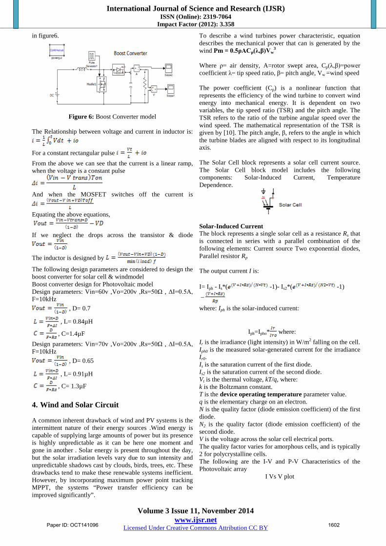
in figure6.
Figure 6: Boost Converter model
The Relationship between voltage and current in inductor is:
For a constant rectangular pulse From the above we can see that the current is a linear ramp, when the voltage is a constant pulse
And when the MOSFET switches off the current is
Equating the above equations,
If we neglect the drops across the transistor & diode
The inductor is designed by
The following design parameters are considered to design the boost converter for solar cell & windmodel Boost converter design for Photovoltaic model Design parameters: Vin=60v ,Vo=200v ,Rs=50Ω , ΔI=0.5A, F=10kHz
, D= 0.7
, L= 0.84µH
, C=1.4µF Design parameters: Vin=70v ,Vo=200v ,Rs=50Ω , ΔI=0.5A, F=10kHz
, D= 0.65
, L= 0.91µH
, C= 1.3µF 4. Wind and Solar Circuit A common inherent drawback of wind and PV systems is the intermittent nature of their energy sources .Wind energy is capable of supplying large amounts of power but its presence is highly unpredictable as it can be here one moment and gone in another . Solar energy is present throughout the day, but the solar irradiation levels vary due to sun intensity and unpredictable shadows cast by clouds, birds, trees, etc. These drawbacks tend to make these renewable systems inefficient. However, by incorporating maximum power point tracking MPPT, the systems “Power transfer efficiency can be improved significantly”.
To describe a wind turbines power characteristic, equation describes the mechanical power that can is generated by the wind Pm = 0.5ρACp(λ,β)Vw
3 Where ρ= air density, A=rotor swept area, Cp(λ,β)=power coefficient λ= tip speed ratio, β= pitch angle, Vw =wind speed The power coefficient (Cp) is a nonlinear function that represents the efficiency of the wind turbine to convert wind energy into mechanical energy. It is dependent on two variables, the tip speed ratio (TSR) and the pitch angle. The TSR refers to the ratio of the turbine angular speed over the wind speed. The mathematical representation of the TSR is given by [10]. The pitch angle, β, refers to the angle in which the turbine blades are aligned with respect to its longitudinal axis. The Solar Cell block represents a solar cell current source. The Solar Cell block model includes the following components: Solar-Induced Current, Temperature Dependence.
Solar-Induced Current The block represents a single solar cell as a resistance Rs that is connected in series with a parallel combination of the following elements: Current source Two exponential diodes, Parallel resistor Rp The output current I is: I= Iph - Is*( -1)- Is2*( -1) –
where: Iph is the solar-induced current:
Iph=Ipho* where: Ir is the irradiance (light intensity) in W/m2 falling on the cell. Iph0 is the measured solar-generated current for the irradiance Ir0. Is is the saturation current of the first diode. Is2 is the saturation current of the second diode. Vt is the thermal voltage, kT/q, where: k is the Boltzmann constant. T is the device operating temperature parameter value. q is the elementary charge on an electron. N is the quality factor (diode emission coefficient) of the first diode. N2 is the quality factor (diode emission coefficient) of the second diode. V is the voltage across the solar cell electrical ports. The quality factor varies for amorphous cells, and is typically 2 for polycrystalline cells. The following are the I-V and P-V Characteristics of the Photovoltaic array
I Vs V plot
Paper ID: OCT141096 1602

International Journal of Science and Research (IJSR) ISSN (Online): 2319-7064
Impact Factor (2012): 3.358
Volume 3 Issue 11, November 2014 www.ijsr.net
Licensed Under Creative Commons Attribution CC BY
P vs V Plot
5. Simulation Results This paper simulated the solar panel with 72 cells, the wind model, the boost converter for the Photovoltaic system and the wind system. The hybrid wind-solar energy system with CUK-SEPIC fused converter replacing the boost converter is also simulated using the MATLAB SIMULINK software. 5.1 Solar Panel Modeling. The inbuilt solar cell has been utilized to design the solar panel using 72 cells with irradiance of 1000 rad/m2. By varying the output load resistance value the output voltage can be varied and the panel power and current can be varied by varying the irradiance supplied. The PV system model is given in Fig and the values for R=13 Ω and R= 10Ω are given in Fig: 7 and Fig: 8 respectively.
Figure 7: PV System Model
Figure 8: Output values of PV system for R=13 Ω
Figure 9: Output values of PV system for R=10 Ω
5.2. Wind Energy System Model The Wind Model with variable pitch angle and wind speed has been given in Fig: 10 and the output values are given in Fig:11
Figure 10: Wind Energy System Model
Paper ID: OCT141096 1603
International Journal of Science and Research (IJSR) ISSN (Online): 2319-7064
Impact Factor (2012): 3.358
Volume 3 Issue 11, November 2014 www.ijsr.net
Licensed Under Creative Commons Attribution CC BY
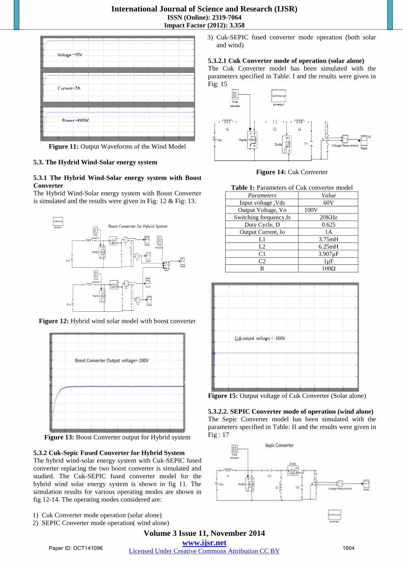
Figure 11: Output Waveforms of the Wind Model
5.3. The Hydrid Wind-Solar energy system 5.3.1 The Hybrid Wind-Solar energy system with Boost Converter The Hybrid Wind-Solar energy system with Boost Converter is simulated and the results were given in Fig: 12 & Fig: 13.
Figure 12: Hybrid wind solar model with boost converter
Figure 13: Boost Converter output for Hybrid system
5.3.2 Cuk-Sepic Fused Converter for Hybrid System The hybrid wind-solar energy system with Cuk-SEPIC fused converter replacing the two boost converter is simulated and studied. The Cuk-SEPIC fused converter model for the hybrid wind solar energy system is shown in fig 11. The simulation results for various operating modes are shown in fig 12-14. The operating modes considered are: 1) Cuk Converter mode operation (solar alone) 2) SEPIC Converter mode operation( wind alone)
3) Cuk-SEPIC fused converter mode operation (both solar and wind)
5.3.2.1 Cuk Converter mode of operation (solar alone) The Cuk Converter model has been simulated with the parameters specified in Table: I and the results were given in Fig: 15
Figure 14: Cuk Converter
Table 1: Parameters of Cuk converter model
Parameters Value Input voltage ,Vds 60V
Output Voltage, Vo 100V Switching frequency,fs 20KHz
Duty Cycle, D 0.625 Output Current, Io 1A
L1 3.75mH L2 6.25mH C1 3.907µF C2 1µF R 100Ω
Figure 15: Output voltage of Cuk Converter (Solar alone) 5.3.2.2. SEPIC Converter mode of operation (wind alone) The Sepic Converter model has been simulated with the parameters specified in Table: II and the results were given in Fig : 17
Paper ID: OCT141096 1604
International Journal of Science and Research (IJSR) ISSN (Online): 2319-7064
Impact Factor (2012): 3.358
Volume 3 Issue 11, November 2014 www.ijsr.net
Licensed Under Creative Commons Attribution CC BY
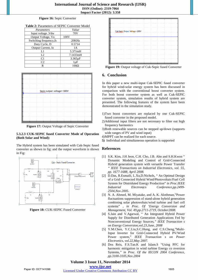
Figure 16: Sepic Converter
Table 2: Parameters of SEPIC Converter Model Parameters Value
Input voltage ,Vdw 70V Output Voltage, Vo 100V
Switching frequency,fs 20KHz Duty Cycle, D 0.5714
Output Current, Io 1A L1 5.371mH L2 7.1433mH C1 3.365µF C2 1µF R 100Ω
Figure 17: Output Voltage of Sepic Converter
5.3.2.3 CUK-SEPIC fused Converter Mode of Operation (Both Solar and Wind): The Hybrid system has been simulated with Cuk-Sepic fused converter as shown in fig: and the output waveform is shown in Fig:
Figure 18: CUK-SEPIC Fused Converter
Figure 19: Output voltage of Cuk-Sepic fused Converter
6. Conclusion In this paper a new multi-input Cuk-SEPIC fused converter for hybrid wind-solar energy system has been discussed in comparison with the conventional boost converter system. For both boost converter system as well as Cuk-SEPIC converter system, simulation results of hybrid system are presented. The following features of the system have been demonstrated in the simulation study. 1) Two boost converters are replaced by one Cuk-SEPIC
fused converter in the proposed model. 2) Additional input filters are not necessary to filter out high
frequency harmonics 3) Both renewable sources can be stepped up/down (supports
wide ranges of PV and wind input) 4) MPPT can be realized for each source. 5) Individual and simultaneous operation is supported References [1] S.K. Kim, J.H Jeon, C.H. Cho, J.B. Ahn and S.H.Kwon “
Dynamic Modeling and Control of Grid-Connected Hybrid generation system with versatile Power Transfer “ IEEE Transactions on Industrial Electronics, vol. 55, pp. 1677-1688, April 2008.
[2] D.Das, R.Esmaili, L.Xu,D.Nichols, “ An Optimal Design of a Grid Connected Hybrid Wind/Photovoltaic/Fuel Cell System for Distriduted Energy Production” in Proc.IEEE Industrial Electronics Conference,pp.2499-2504,Nov.2005.
[3] N. A. Ahmed, M. Miyatake, and A. K. Alothman,”Power fluctuations suppression of stand-alone hybrid generation combining solar photovoltaic/wind turbine and fuel cell systems” , in Proc. Of ‘Energy Conversion and Management, Vol. 49,pp.2711-2719, October2008.
[4] S.Jain and V.Agarwal, “ An Integrated Hybrid Power Supply for Distributed Generation Applications Fed by Nonconventional Energy Sources,” IEEE Transaction s on Energy Conversion,vol.23,June, 2008
[5] Y.M.Chen, Y.C.Liu,S.C.Hung, and C.S.Cheng,”Multi-Input Inverter for Grid-Connected Hybrid PV/Wind Power system,” IEEE Transaction s on Power Electronics, vol.22,May 2007.
[6] Dos Reis, F.S.Tan.K and Islam.S “Using PFC for harmonic mitigation in wind turbine Energy co nversion Systems,” in Proc. Of the IECON 2004 Conference, pp.3100-3105,Nov.2004
Paper ID: OCT141096 1605

International Journal of Science and Research (IJSR) ISSN (Online): 2319-7064
Impact Factor (2012): 3.358
Volume 3 Issue 11, November 2014 www.ijsr.net
Licensed Under Creative Commons Attribution CC BY
[7] R.W.Erickson,”Some Topologies of High Quality Rectifiers “in the Proc. of the First International Conference on Energy, Power, and Motion Control, May 1997.
[8] D.S.L.Simonetti,J.Sebastian and J.Uceda, “ The Discontinuous Conduction Mode Sepic and Cuk Power Factor Preregulators: Analysis and Design “ IEEE Trans.on Industrial Electronics, vol.44, no.5, 1997.
[9] N.Mohan, T.Undeland and W.Robbins “Power Electronics: Converters, Applications and Design,” John Wiley & Sons, Inc., 2003.
[10] J.Marques, H.Pineheiro, H.Grundling, J.Pinheiro “ A Survey on Variable-Speed Wind Turbine System,” Proceedings of Brazilian Conference of Electronics of Power , vol.I, pp.732-738,2003.
[11] Teena Jacob and Arun S, “Modeling Of Hybrid Wind And Photovoltaic Energy System Using A New Converter Topology “Electrical and Electronics Engineering: An International Journal (EEEIJ) Vol.1, No.2, August 2012.
Author Profile
Simhadri Lakshmi Sirisha is a M.Tech Student in Power electronics and Electrical Drives Specialization, in Vasireddy Venkatadri Institute of Technology, Nambur. She has completed
B.Tech from Vignan’s Engineering College, Vadlamudi. Her Areas of interest are Hybrid Energy Systems, Multilevel Inverters.
Ambati Hariprasad is working as Assistant Professor in Department of Electrical and Electronics Engineering in Vasireddy Venkatadri Institute of Technology from August, 2007. He has completed his
Master of Technology in Power Electronics and Electric Drives. He has eight publications in power electronics with renewable energy sources. His fields of interest are solar energy, Electric Vehicles.
Paper ID: OCT141096 1606