Embed Size (px)
Citation preview

MASTERARBEIT
Titel der Masterarbeit
„A process model template for the support of
IT-based logistics planning in the context of Chinese
ports”
Verfasser
Bakk. Zhan CHEN
angestrebter akademischer Grad
Diplom-Ingenieur (Dipl.-Ing.)
Wien, 2012
Studienkennzahl It. Studeinblatt: A 066 926
Studienrichtung It. Studienblatt: Masterstudium der Wirtschaftsinformatik
Betreuer: Univ.-Prof. Dipl.-Ing. DDr. Gerald Quirchmayr
B
Deutsche Abstract
In den letzten 10 Jahren hat die Verwaltung chinesischer Häfen große Fortschritte bei IT-Systemen
gemacht. Aber im Vergleich zu anderen Industrieländern sind chinesische Häfen in Bereichen wie
Design, Entwicklung und Implmentierung des IT-Systems noch am Anfang. Die meisten Probleme
sind, dass das aktuelle IT-System nicht genügende Austausch von Informationen und
Kommunikationsmöglichkeiten liefern kann. Die Situation lässt sich durch isolierte
Informatiosinseln, Redudanz der Systemstruktur, ineffiziente Entwicklung und in einigen Fällen
sogar fehleranfällige Entwicklung kennzeichnen.
In dieser Magisterarbeit wurde ein neues „Design-Prozess-Modell“ für die logische Modellierung
des gesamten Informationssystems in chinesischen Häfen entworfen. Das
„Design-Prozess-Modell“ gilt nicht nur als ein Standard-Prozess-Modell für die Unternehmen, das
IT-System zu entwerfen, es ist sondern auch eine Sammelung von einigen Methoden, Mustern und
Regeln für die Designer, das Design-Konzept anzuwenden.
Der Hauptzweck des geplanten "Design-Prozess-Modell" besteht darin, ein kohärenteres, besser
strukturiertes und dokumentiertes System für die Entwicklung des IT-Systems zur Verfügung zu
stellen und logische Beziehungen und Zusammenhänge zwischen den verschiedenen Modellen zu
gewährleist.
Folgende Schritten sollen im „Design Process Model“ inkludiert werden.
1) Identifikation der eigneten Modelle für Entwicklung des IT Systems
2) Spezifikation von transformation rules zwischen unterschiedliche modele.
3) Semantik, Syntax und Notifikation des Vorgangsmodels zu formulieren.
4) Entwicklung der eigneten “Software Development Management Approach“.
Schlagwörter: Vorgangsmodel, Software Entwicklung Management, MDA, Model
Transformation
Master Thesis
„A process model template
for the support of IT-based
logistics planning in the
context of Chinese ports”
Author
Zhan CHEN
a0408735
In Partial Fulfillment of the Requirements for the Degree Master of
Wirtschaftsinformatik
Vienna, 2012
Studienkennzahl It. Studeinblatt: A 066 926 (2006)
Studienrichtung It. Studienblatt: Wirtschaftsinformatik
Betreuer: Univ.-Prof. Dipl.-Ing. DDr. Gerald Quirchmayr
1
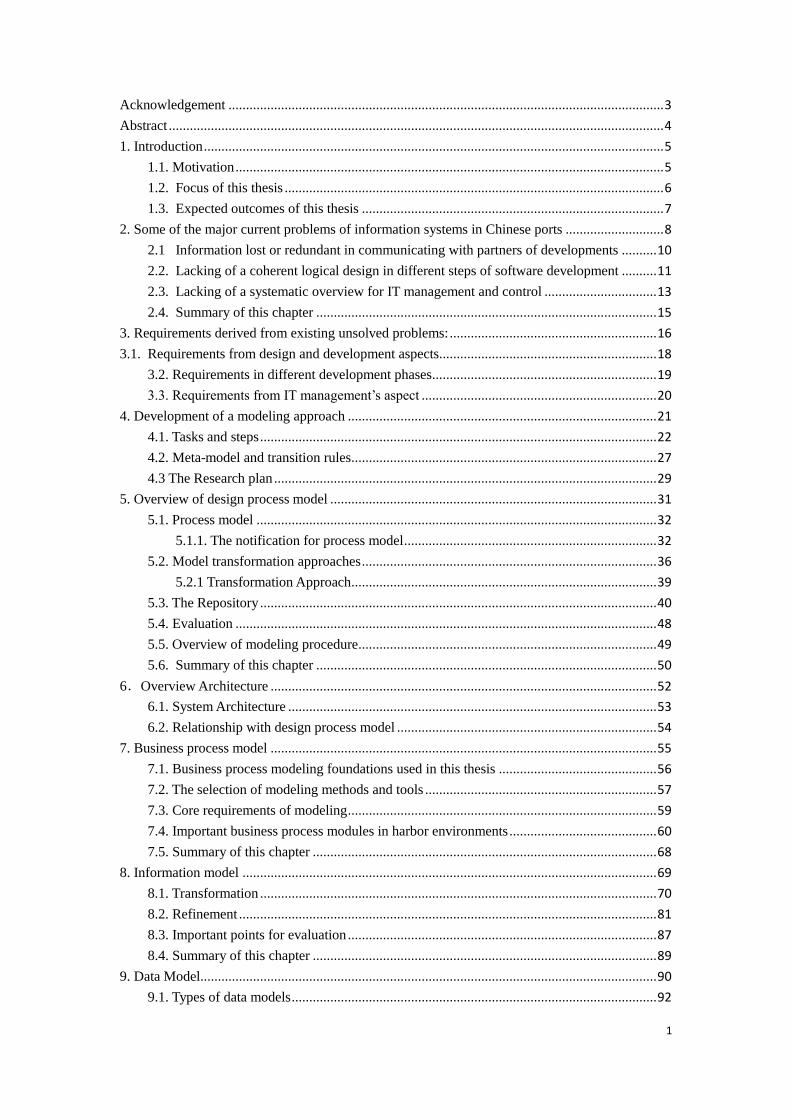
Acknowledgement ............................................................................................................................ 3
Abstract ............................................................................................................................................. 4
1. Introduction ................................................................................................................................... 5
1.1. Motivation .......................................................................................................................... 5
1.2. Focus of this thesis ............................................................................................................ 6
1.3. Expected outcomes of this thesis ...................................................................................... 7
2. Some of the major current problems of information systems in Chinese ports ............................ 8
2.1 Information lost or redundant in communicating with partners of developments .......... 10
2.2. Lacking of a coherent logical design in different steps of software development .......... 11
2.3. Lacking of a systematic overview for IT management and control ................................ 13
2.4. Summary of this chapter ................................................................................................. 15
3. Requirements derived from existing unsolved problems: ........................................................... 16
3.1. Requirements from design and development aspects.............................................................. 18
3.2. Requirements in different development phases ................................................................ 19
3.3. Requirements from IT management’s aspect ................................................................... 20
4. Development of a modeling approach ........................................................................................ 21
4.1. Tasks and steps ................................................................................................................. 22
4.2. Meta-model and transition rules ....................................................................................... 27
4.3 The Research plan ............................................................................................................. 29
5. Overview of design process model ............................................................................................. 31
5.1. Process model .................................................................................................................. 32
5.1.1. The notification for process model ........................................................................ 32
5.2. Model transformation approaches .................................................................................... 36
5.2.1 Transformation Approach ....................................................................................... 39
5.3. The Repository ................................................................................................................. 40
5.4. Evaluation ........................................................................................................................ 48
5.5. Overview of modeling procedure ..................................................................................... 49
5.6. Summary of this chapter ................................................................................................. 50
6.Overview Architecture .............................................................................................................. 52
6.1. System Architecture ......................................................................................................... 53
6.2. Relationship with design process model .......................................................................... 54
7. Business process model .............................................................................................................. 55
7.1. Business process modeling foundations used in this thesis ............................................. 56
7.2. The selection of modeling methods and tools .................................................................. 57
7.3. Core requirements of modeling ........................................................................................ 59
7.4. Important business process modules in harbor environments .......................................... 60
7.5. Summary of this chapter .................................................................................................. 68
8. Information model ...................................................................................................................... 69
8.1. Transformation ................................................................................................................. 70
8.2. Refinement ....................................................................................................................... 81
8.3. Important points for evaluation ........................................................................................ 87
8.4. Summary of this chapter .................................................................................................. 89
9. Data Model .................................................................................................................................. 90
9.1. Types of data models ........................................................................................................ 92

2
9.2. Transformation approach ................................................................................................. 93
9.2.1 Information model transformation ......................................................................... 93
9.2.2 Information model refinement ............................................................................. 103
9.2.3. Data structure model transformation ................................................................... 106
9.2.4. Data structure model refinement ......................................................................... 114
9.3. Summary of this chapter ................................................................................................ 116
10. Infrastructure model ................................................................................................................ 117
10.1. Definition of the Infrastructure model ......................................................................... 118
10.2. Transformation ............................................................................................................. 120
10.3. Refinement ................................................................................................................... 123
10.4. Summary of this chapter .............................................................................................. 126
11. Conclusion and outlook ........................................................................................................ 127
12. Literature ............................................................................................................................... 129

3
Acknowledgement
Foremost, I would like to thank my family: my parents Hangzhu Chen and Min Li, for
giving birth to me in the first place and supporting me spiritually and materially
throughout my life. Without their encouragement and understanding it would not have
been possible for me to finish my master study.
I would like to express my sincere gratitude to my advisor Univ.-Prof. Dipl.-Ing. DDr.
Gerald Quirchmayr for the continuous support of this thesis and my whole master
study, for his patience, motivation, enthusiasm, and immense knowledge. His
guidance helped me in all the time of research and writing of this thesis. I could not
have imagined having a better advisor and mentor for my master study.
Besides my advisor, I would like also to thank for the support of professor Lei Huang
and his doctor Student Xi Song from the China-Austria Research and Innovation
Center in Logistics, Information Flow, Supply Chain Management and Material Flow,
because without their information and guidance on existing logistics environments
and information systems in Chinese port administrations I could not have carried out
this research.
This work has been supported by Eurasia Pacific Uninet through the China-Austria
Research and Innovation Center in Logistics, Information Flow, Supply Chain
Management and Material Flow, which I am very grateful for.
4
Abstract
In recent years, Chinese harbor administrations have made great progress in IT
development. But in the aspect of design, development and implementation, China is
still in its infancy compared with other industrialized countries. Most problematic is
that current information systems cannot provide enough information sharing and
communication capabilities. The situation is best characterized by isolated
information islands, system structure redundancies, and inefficient development and
in some cases even failure-prone development.
In this thesis, a tailored “design process model” is utilized for the logical modeling of
more holistic information systems in Chinese harbors. The “design process model” is
not only envisaged to serve as a standard process model to design the IT system in the
enterprise, but also a collection of some methods, patterns and rules to help designers
to finish the design concept. It does therefore go beyond a model and does incorporate
some components of a framework.
The main purpose of the planned “design process model” is to create more coherent
and better-structured and documented system models for IT system development
automatically and to ensure logical relationships and coherences between different
models.
To build the model the approach has to include the following steps:
1) Identification of a suitable model for developing IT systems
2) Specification of transformation rules between the different models.
3) Formulation of Semantics, syntax and notification for the process model.
4) Development of a sustainable software development management approach.
Keywords: Process model, software development management, MDA, Model
transformation
5
1. Introduction
1.1. Motivation
With economic globalization, global trade liberalization and intergradations of
international transport market, the growth rate of international trade is significantly
higher than the speed of economic growth. Therefore, as land & water transportation
hub and goods distribution& logistic center, harbors face challenged as never before.
In China, there is a similar situation: with high growth rate of Chinese economy, the
volume of international imports and exports grows very fast in recent years.
Meanwhile, due to its important role in the whole imports and exports transaction,
Chinese harbors are always under public attention. There are significant amount of
research put the development of Chinese harbors. Meanwhile, experts, scientists and
managers in China are striving to find out the appropriate way to develop Chinese
harbors to make them meet the requirements of high rates of development of
international imports and exports.
Meanwhile, as an important part and a criterion of modernization level of harbors, the
information system is now another hot topic in Chinese harbors development.
In recent years, Chinese harbors have made great progress in Information system
development. Most logistics center, marine harbors have already had complete
information system to support harbors business activities. But there are still a lot of
problems, for example, in the aspect of system design, development and complexity
of system, China is in its infancy compared with other developed countries. The
information system cannot provide enough information sharing and communication.
The situation is characterized by isolated information island, system structure
redundancy, inefficient development and false development.
Furthermore, there is not yet a standard way to develop IT systems for supporting the
harbor business. The pattern is generally like that the developer designs or develops
IT systems in harbor directly according to the requirements from customer; the
updating of development is unsustainable and not logical. Therefore, the affectivity
and quality of information management systems is very difficult to guarantee.
On the other side, the trend of developing information management systems in
harbors is based on business processes. Thus, with the development of the SOA
Architecture and clouding technology, those new technologies are more and more
applied in Information system in harbors. So the emphasis of research in China has
moved from implementation technology to optimizing the integration of new
techniques into old systems. Therefore, a topic like how to develop and integrate new
6
system into old system is very popular.
Under these circumstances, a standard and logical development method is needed and
stakeholders who are involved in development procedure hope through this method to
improve quality of development and information system itself. Therefore, this thesis
tries to provide a new concept to improve the way and method in the field of
designing and implementing of Information systems for Chinese harbors and also to
find out a solution for development, optimal integration and sustainable updating in
aspect of Designing.
1.2. Focus of this thesis
Developing or updating an IT system basing on often changed business process is a
very complicate procedure. It includes knowledge such as Software engineering,
project management, business management and so on. It is impossible to descript
exactly how to develop and update a system optimally in a thesis. However, people
always say: “Well begun is half done”. As first step for system developing, the design
is a very important phase in whole developing procedure. If we can solve the problem
in design phase, then the success is not far away from us.
Meanwhile, as an important method describing design concepts, system modeling is
used widely in design phase of software developments. In additional, OMG
organization has already provided a trail of modeling standards and methods to help
people to describe system design and development. MDA, Model2code
transformation technologies let implementation more comprehend, so from these
points, we assume, perhaps the problems in above can be voided by using a logical
modeling method.
Therefore, according above assumptions and experiences in past developments, a new
system design process is created for improving quality of system development in this
thesis, the theory of this “design process model” is introduced to readers at first and
then through a concrete example the “design process model” will explained deeper.
To achieve and finalize the design process model, following aspects should be
processed:
1) Identification of a suitable model for developing IT systems
2) Specification of transformation rules between the different models.
3) Formulation of Semantics, syntax and notification for the process model.
4) Development of a sustainable software development management approach.
7
1.3. Expected outcomes of this thesis
The main purpose of this “design process model” is to create different system models
for IT system development automatically and to ensure logical relationships and
coherences between different models.
In additional, The “design process model” is not only a standard process model to
design the IT system in enterprise, but also a collection of some methods, patterns and
rules for helping designers to finish design concepts. It is more like a framework
which rules logics between system models and users.
Therefore, through creating and utilizing the “design process model” for designing
information system in Chinese harbor in this thesis, a new approach to design and
model information systems will be present. Meanwhile, through researching the
transformation methods and technologies, this thesis provides a plenty of modeling
patterns and realization approaches for model transformation. This methods and
transformation technologies can be used in many aspects of software modeling and
software development.
Thus, as a part of process model, a lot of software development management methods
are also developed in this thesis. Developers and designers in different teams or in
different development phases can more easily understand philosophies of design and
to ensure the quality of system in aspect of organization.
Generally, the goal of this design process model is to reduce risks of integration
mistake, false development and to improve efficiencies of software development.

8
2. Some of the major current problems of information
systems in Chinese ports
As discussed in the introduction, the development of Information systems in Chinese
harbors is not mature and systematic; there are many problems in the scope of
information system development and application. In past few years, the growth rate of
the Chinese GDP has been maintained at 8%- 9% in average. The life quality for
Chinese has also been changed in accordance to the high-level economy rates.
Similarly, in the field of business, global cargo and bulk transfer quantity has been
increased significant. The situation of marine transport in 1996-2006 can been seen in
the following table, from which a growth of 10% with regard to the volumes of
marine transport can be witnessed in past decade. These Data indicate that the
economy and business grow rapidly in China, reflecting which, the business process
in Chinese harbors has been changed accodingly. However, the abovemetioned
situation brings out a couple of issues: how can designers or developers make sure
that IT systems in harbors meet the the requirements of the evolving business scales?
Are existing systems and experiences of system development from other countries
applicatable for Chinese harbors? If not, how can they be improved and modified?
Figure 1, Development of container transit in Chinese harbors and in Rotterdam 1
Besides, there are some similar problems in the field of continual integration between
new and old systems:
1 Source: China statistical yearbook 2006

9
The information system of Harbor should be modularized, standardized and easy to
integrate or to take off. The IT system in Chinese Harbors is required to be updated
frequently to keep abreast with the requirements of the growing business modes and
user demand, which brings difficulties to developers in standardizing and integrating
information systems. It can also cause problems, such as Data redundant or
information lost.
In addition, it is not practical to implement the requirements from business directly
into IT system. Considerable amount of business and logical information could be lost
by the direct implementation method, which also can lead to problems in the
integration and further expansion. Integration or new module development would
become “mission impossible” without a clear designing concept and a standardized
method.
And from the point of IT management, an overview of whole IT concept helps users
to understand and control the whole system. Different aspects of system are usually
described by different models. However, in this way, each model corresponds to a
particular aspect and the relationship between different models cannot be identified.
Therefore, it is a challenge to organize the models in a logical overview and to
describe relationships between them.
In this chapter, the issues mentioned above will be discussed systematically. In
addition, the research approach and a proposal to resolve these problems will also be
suggested.
10
2.1 Information lost or redundant in communicating with
partners of developments
As discussed in the introduction above, the Information management System in
harbors is rather complicate. It includes certain amount of sub-systems and
extra-systems from other business partners, which makes the completion of
development a challenging task. In this section, the problems in communicating with
other stakeholders of system development will be addressed.
Firstly, from the very beginning of the development, the developers must have a
thorough understanding of the requirements of customers and the business processes.
Development methods and plans have to be defined accordingly, based on the demand.
However, a particular piece of information can easily be converted to various
implementation concepts. For example, very often, one project can be taken by more
than one development teams, which are responsible for different parts in the
integration. Despite the adoption of same implementation technologies and efficient
communication, problems such as mapping, information lost and integration mistake
are still unavoidable.
Secondly, different models are used by system designers to describe, communicate
and present to other partners. However, an IT system includes a number of aspects
that the designer or developer have to consider, such as business description, data
concept, and system architecture. The corresponding models that used by the designer
to explain those aspects and the relationship between them may not necessarily be
understood by other stakeholders, such as business managers, users, code developers,
and even designers of other sections. For example, a business manager drafts a
business process to explain the flow and requirements of business realities, based on
which a system designer is required to design a system model. The system designer
must consider: firstly, if the business models provide enough information to finish
further system design; and secondly, if there is a general rule on the “business to
system” transformation and if the design is actually based on the business process.
Similar problems can also be found in the following case: If a model is designed by
more than one development teams, different parts of this model from different teams
must be coordinated and mapped. The mapping can however not achieve a 100%
match without semantic checking, communication and coordination. Nevertheless,
this procedure is not cost-effective and efficient. Therefore, a solution or method to
avoid the mapping procedure is urgently in demand.
11
2.2. Lacking of a coherent logical design in different steps
of software development
There are several levels in software development: system designers define the
developing concept, code programmers implement this concept, and IT manger
control and plan the whole development lifecycle. For the purpose of understanding
the logic and ensuring the coherence of development in different levels, a
standardized method to describe and define the whole development process must be
adopted for all the team members to achieve this goal.
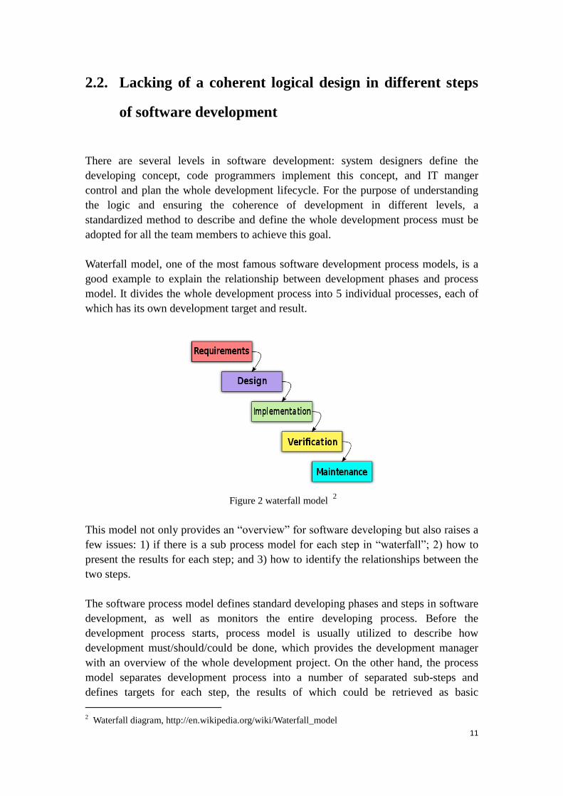
Waterfall model, one of the most famous software development process models, is a
good example to explain the relationship between development phases and process
model. It divides the whole development process into 5 individual processes, each of
which has its own development target and result.
Figure 2 waterfall model 2
This model not only provides an “overview” for software developing but also raises a
few issues: 1) if there is a sub process model for each step in “waterfall”; 2) how to
present the results for each step; and 3) how to identify the relationships between the
two steps.
The software process model defines standard developing phases and steps in software
development, as well as monitors the entire developing process. Before the
development process starts, process model is usually utilized to describe how
development must/should/could be done, which provides the development manager
with an overview of the whole development project. On the other hand, the process
model separates development process into a number of separated sub-steps and
defines targets for each step, the results of which could be retrieved as basic
2 Waterfall diagram, http://en.wikipedia.org/wiki/Waterfall_model
12
knowledge for next steps in developing. This loosely connected module can not only
ensure the coherence and logic of software development but also meet requirements
for ad-hoc developing.
The concept of process model may have further indication on the following questions:
1) if it is possible to design or if there is an existing standardized process model in the
system design phase? 2) If this process model can make sure the coherence of
information and transfer of logical thinking. 3) How can this design process model
integrate in existing software development process model?
13
2.3. Lacking of a systematic overview for IT management
and control
IT system in a corporation or enterprise, for the consideration of management, must
be administrated by computer section or CIO, who is in charge of the whole IT
relative issues, such as planning, managing, and maintaining of IT system. The IT
management covers the gaps between enterprise business activities and technologies.
The six primary responsibilities of CIO are:3
1) Understand the business and the markets in which the firm sells its products and
services.
2) Establish credibility of the IS department, thereby increasing the confidence of
executive management in ideas presented by IS management
3) Develop a competent IS staff and IT Savvy users. So the enterprise can leverage
IT.
4) Create a vision of the future and sell it, by working to set a goal for the use of IT
within the enterprise and convincing others to embrace this vision.
5) Implement an information system architecture that will support the vision and the
company in future.
6) Foster relationships with senior management, line executives, suppliers, alliance
partners, and customers, both external and internal.
Seen from the above listed six responsibilities, CIO is head of the IS Management and
controls the whole IS development Trend. The CIO may not necessarily aware of each
details of the system, but he/she must understand the general situation and status of
the IT system. In this way, the CIO focuses not only on the IT system, but also on
other aspects in the enterprise, such as IT strategy, development plan, development
cycles control, cost calculation and demand for IT system. Therefore, a CIO and
whoever is in charge of a section of IT system would need a method to provide an
detailed overview of IT system in enterprise, with which the CIO or manager can
understand the general information about IS systems.
It would be idea to use a model to present the whole concept of IT system. However,
as mentioned in the previous discussion, integrating various models in an “overview”
is a problem that needs to be resolved. The system model can provide an overview of
system like a blueprint in the construction field. Similar to the blueprint, different
aspects of the IT system is designed initially with a defined progress and then
integrate into an “overview map”. The issues are: how to integrate these separate
3 Information systems management in practice fifth edition, by Barabara C. Mcnurlin, Ralph H.
Sprague,JR

14
“concepts” into one “overview” and how to ensure the logical relationship among
different “concepts” in “overview” in software development.

15
2.4. Summary of this chapter
Seen the three sections above, problems about designing and developing IT system in
enterprise can be summarized into three aspects:
1) Information variation generated in the communication with other
stakeholders
Despite efficient communication and coordinating protocol between different
development teams or developers, problems such as information lost and redundancy
can be caused by different understanding of designs. Frequent meeting and timely
coordination can reduce the possibility of unexpected changes. However, the
alternation of information cannot be totally avoided. Therefore, the first challenge is
to ensure the coherence of system design and reduce information variation.
2) Lacking of logically coherent design steps in different phases of software
development
There is not yet a standardized way to develop IT systems that support the harbor
business. The present operation mode is that the developer designs or develops IT
systems in harbor directly according to the requirements from customers. However,
the update of development is unsustainable and illogical. Therefore, the affectivity
and quality of information management systems is guaranteed.
3) Lacking of a systematic overview for IT management
System designers describe their designs with different system models. But those
designs are just parts of a model. However, the integration of these separate “concepts”
into one “overview” and the insurance of logical relationship among different
“concepts” in an “overview” remain as challenges in the system development.

16
3. Requirements derived from existing unsolved problems:
The problems of system development in Chinese harbors are addressed in the
previous chapter. These problems can be considered as requirements expected by
stakeholders who involve in the development procedure. This chapter will therefore
discuss the demand of a new design process model based on the above-mentioned
problems. These requirements are discussed not only a summary of existed problems,
but also as the basis and motivation of creating and researching new design process
model.
According to the problems in the previous chapter, the requirements are summarized
into the following 3 aspects:
1) From the design and development aspects
1.1) A standardized process model for software design process and design
sequence should be defined by using this process.
1.2) The design sequence describes not only the process of design but also
results and sequenced activities for each step.
1.3) The process model should also maintain the coherence of logic and design
thinking.
1.4) The process model must also have logical rules for results transaction. For
example, the rules and methods for transaction from business model to data
model.
1.5) The process model is also a framework, which provides method for
integration of different Models
2) For integration and updating
2.1) for further updating and integration of new system, each result from each
phase in process model should be presented separately.
2.2) presentation of design logic and design thinking
2.3) this process model must be iterative and each result in each step can be
changed for further developing.

17
3) In IT Management aspect
3.1) This process model can provide an overview of system
3.2) This process model can help CIO or IT management to make IT
development plan and strategy
3.3) This process model should be a bridge between IT engineer and enterprise
normal employees.
3.4) Blue print about the enterprise’s information system.
In this chapter, all above aspects in requirements will be further explained and the
basis of creating a new design process model can be established from these
requirements.
18
3.1. Requirements from design and development aspects
Seen from chapter 2, information lost and redundancy can be caused in the
communication among development members and there is also no method to
guarantee the transmission of design logic among different develop members.
Therefore, the first requirement summarized from the problems is that a new
developments plan should have a very clear method to determine the way
stakeholders in development communicating and coordinating with each other. Thus,
the maintenance of coherence of logic and design is another basic requirement.
On the other hand, design and developing after certain process model is considered as
a good approach to manage and control the whole development. Therefore, after
considering both sides of the problems, more detailed requirements can be concluded:
Firstly, the design process model is like a normal process model, which rules and
determines the whole design process steps as well as defines results from each step.
This standard process provides developers and designers with a common basis for
communicating and coordinating design results. Considering problems of information
lost and redundancy, the design process model should contain methods to record
logics and ideas behind each design. These records should be comprehended easily
and completely, so that they can be transmitted among different stakeholders.
Generally, the new design process model should be a standardized modeling process,
which can provide developer with clear information and business logic as well as
transformation rules, design patterns, modeling steps. By adopting this “standard
modeling process”, the end-user who has no IT knowledge should easily understand
the logic and philosophy of the design. The situation such as information lost data
redundant and mapping procedure can therefore be avoided. All the requirements
from design and development aspects are illustrated in following diagram:

19
3.2. Requirements in different development phases
The design and development from different teams or stakeholders in one development
phase can be observed as horizontal development process. In the same way, design
and development between different phases can be observed as a vertical development
process.
Similar to the horizontal development process, the vertical development process also
requires guarantee on design and development coherence. Therefore, the design
process model should have not only methods to record logics behind design, but also
the logic in transformation between different models. These logical transformation
methods can ensure that there are no logical changes in different development phases.
The present method of customers bringing up some requirements, and then developers
or designers implementing the system accordingly is thus strictly forbidden. If
information systems are developed in this way, structures and architectures of system
can be confused, which could be a disaster for further developments and system
integrations. Therefore a gradual process with clear design goals is crucial and
necessary, which rules different phases and sub-goals of fulfilling customers’
requirements. Furthermore, through the method of dividing general concept into sub
concepts can better ensure the logic and coherence of design.
On other side, the general–sub concept organization is helpful for iteration. The final
design concept usually cannot be finished in one time. Constant improvements and
alteration are necessary to meet the changing requirements. Therefore, an iterative
system is another requirement of our design process model, which allows designers to
improve or change designs without confusion through evaluation of business request.

20
3.3. Requirements from IT management’s aspect
The IT Management is responsible for the whole information system. They manage
some of the most important tools that can influence the firm’s future. Presenting IT
manager with an overview of the whole system situation optimally is a priority, which
brings up another requirement for the design process model. It should provide an
overview to IT manger, which can help IT management plan and control entire system
development and make corresponding decisions.
Design process model should also provide architecture for information system, like a
blueprint. It shows how the overall system, house, vehicles, or other product look like
and the way different parts interrelate. The design process model should also organize
those aspects together as well as plan and control tools.
In additional, another mission of IT management is to overcome the gap between
technical issues and business issues, which means that IT management is responsible
for popularizing and introducing information system to non-technical members in the
enterprise, so that they can understand features of systems. However, tedious
technical reports and different analyzing data create difficulties for other stakeholders
to understand and accept the systems. It is also not an easy task for technical members
to introduce their products with a clear system model.
Lastly, the design process is required to be easy to understand and clearly presented.
The IT managers can therefore present IT system with it and involve other
stakeholders in the further development and updating.

21
4. Development of a modeling approach
In previous chapters, the problems and requirements in the development of
Information system have been discussed, which brings up the question that whether
there is a way or method to fulfill the needs?
After analyzing the requirements in above chapters, it can be concluded that a good
design concept should present not only the design logic, but an overview of the IT
system for CIO or IT management to control. From another point of view, different
models can be utilized as a common method to present design concepts. Therefore, it
is assumed that there is a design process model, which can organize the whole design
phase and also explain the relationship between different models.
Further issues are: if there is a standard developing procedure; whether it can be
utilized to avoid situations like information lost or information redundancy in the
system integration; and in this standardized development procedure, whether
information about the developing itself can be acquired to reduce the possibility of
system errors.
A standardized process model for IT system design is considered by this paper as an
effective method to solve the problems, such as expression of logical thinking or
controlling the software development. With regard to the establishment of this process
model, the following sub-questions must be resolved:
1) What should be modeled?
Generally speaking, in the design phase, the overall concept about IT system
should be fixed. Therefore, it is required to model the aspect and scope of the
design concept; decide the steps or phases in this process model, anticipate the
results that may gain from those steps, the sequence of the steps, determine the
potential requirements of information system development for Chinese
harbors.
2) Meta-model and transition rules.
The meta-model is a semantic and syntax base of a model, that we cannot
avoid this step to jump to the direct design and use our process model.
Whereas, the types of model language or method which this meta-model
should be designed and developed is yet to be decided.
On the other side, different models and results can be developed in different
phase of the process model. The transition or integration rule to ensure the
deducing among two or three different models should also be considered.

22
3) Useful existing methods and tools
What kind of research method should be chosen? Are there any existing
methods that can be used directly? Which one can be used to develop the
process model? What kind of tools are helpful to develop the process model?
4.1. Tasks and steps
The initial consideration is the tasks or steps in the process model and logical
relationships among these steps. For example, in the waterfall model, the software
development is divided into different steps, such as “requirement”, “design”,
“implementation”, and “validation”. Whereas, what are the tasks or steps in the design
process model? Which aspects should be considered in the design phase?
An effective way to solve these issues is to base the design phases in various existed
process model, which defines exactly what kind of tasks or work should be carried out
in the design phrase.
In chapter two, the waterfall model is used as an example to explain why we need to
design model. But in the research about the necessary activates in design, all different
kinds of process models should be gathered as much as possible to analyze features of
design.
There are many process models to help people manage and control the software
development:
Waterfall model
Spiral model
V-model
Prototype development
Depending on the above software development models, there are also some
methodologies for software development. Through research on these software
development methodologies, features about methodologies can be concluded and
inspiration can be found.
23
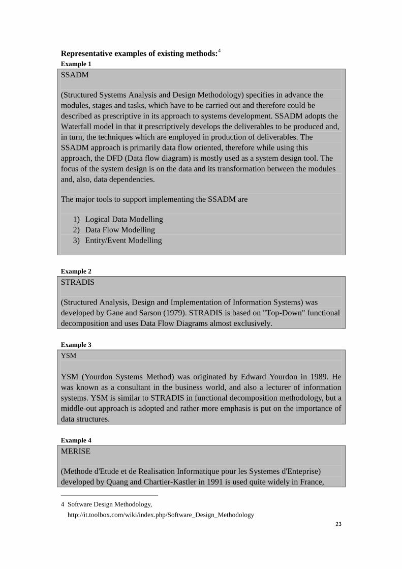
Representative examples of existing methods:4
Example 1
SSADM
(Structured Systems Analysis and Design Methodology) specifies in advance the
modules, stages and tasks, which have to be carried out and therefore could be
described as prescriptive in its approach to systems development. SSADM adopts the
Waterfall model in that it prescriptively develops the deliverables to be produced and,
in turn, the techniques which are employed in production of deliverables. The
SSADM approach is primarily data flow oriented, therefore while using this
approach, the DFD (Data flow diagram) is mostly used as a system design tool. The
focus of the system design is on the data and its transformation between the modules
and, also, data dependencies.
The major tools to support implementing the SSADM are
1) Logical Data Modelling
2) Data Flow Modelling
3) Entity/Event Modelling
Example 2
STRADIS
(Structured Analysis, Design and Implementation of Information Systems) was
developed by Gane and Sarson (1979). STRADIS is based on "Top-Down" functional
decomposition and uses Data Flow Diagrams almost exclusively.
Example 3
YSM
YSM (Yourdon Systems Method) was originated by Edward Yourdon in 1989. He
was known as a consultant in the business world, and also a lecturer of information
systems. YSM is similar to STRADIS in functional decomposition methodology, but a
middle-out approach is adopted and rather more emphasis is put on the importance of
data structures.
Example 4
MERISE
(Methode d'Etude et de Realisation Informatique pour les Systemes d'Enteprise)
developed by Quang and Chartier-Kastler in 1991 is used quite widely in France,
4 Software Design Methodology,
http://it.toolbox.com/wiki/index.php/Software_Design_Methodology
24
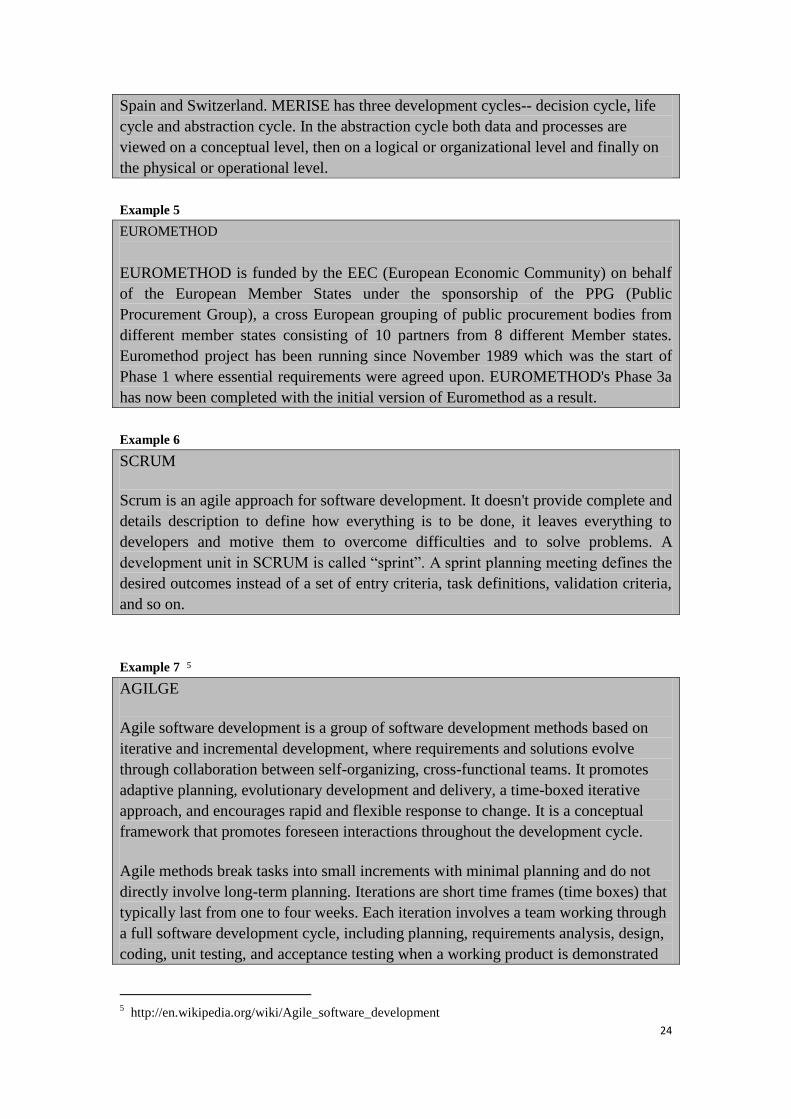
Spain and Switzerland. MERISE has three development cycles-- decision cycle, life
cycle and abstraction cycle. In the abstraction cycle both data and processes are
viewed on a conceptual level, then on a logical or organizational level and finally on
the physical or operational level.
Example 5
EUROMETHOD
EUROMETHOD is funded by the EEC (European Economic Community) on behalf
of the European Member States under the sponsorship of the PPG (Public
Procurement Group), a cross European grouping of public procurement bodies from
different member states consisting of 10 partners from 8 different Member states.
Euromethod project has been running since November 1989 which was the start of
Phase 1 where essential requirements were agreed upon. EUROMETHOD's Phase 3a
has now been completed with the initial version of Euromethod as a result.
Example 6
SCRUM
Scrum is an agile approach for software development. It doesn't provide complete and
details description to define how everything is to be done, it leaves everything to
developers and motive them to overcome difficulties and to solve problems. A
development unit in SCRUM is called “sprint”. A sprint planning meeting defines the
desired outcomes instead of a set of entry criteria, task definitions, validation criteria,
and so on.
Example 7 5
AGILGE
Agile software development is a group of software development methods based on
iterative and incremental development, where requirements and solutions evolve
through collaboration between self-organizing, cross-functional teams. It promotes
adaptive planning, evolutionary development and delivery, a time-boxed iterative
approach, and encourages rapid and flexible response to change. It is a conceptual
framework that promotes foreseen interactions throughout the development cycle.
Agile methods break tasks into small increments with minimal planning and do not
directly involve long-term planning. Iterations are short time frames (time boxes) that
typically last from one to four weeks. Each iteration involves a team working through
a full software development cycle, including planning, requirements analysis, design,
coding, unit testing, and acceptance testing when a working product is demonstrated
5 http://en.wikipedia.org/wiki/Agile_software_development

25
to stakeholders. This minimizes overall risk and allows the project to adapt to changes
quickly. Stakeholders produce documentation as required. Iteration might not add
enough functionality to warrant a market release, but the goal is to have an available
release (with minimal bugs) at the end of iteration.6 Multiple iterations might be
required to release a product or new features.
Seen from these design methodologies, the following types of activities or aspects in
design phase people are worth paying attention to:
Example 87
Preliminary Data Structure Design—a design for the organization of all the data
needed to support a business area. Although still only a Logical representation, the
target DBMS is considered and data is shown in the form of record types and the
linkages between them;
Procedure Design—determining how an individual process will be carried out by
one or more procedures and the design of fallback procedures;
Dataflow Diagrams—a method of representing the various procedures required to
support a given process, the physical data, which flows between them and the data
stores required;
Code Design—deciding what fields are to be encoded, the style and format most
appropriate in each case and defining who will create/maintain the codes;
System Structure Design—techniques to determine how the various procedures will
be linked together, security, control and audit procedures required etc.;
Prototyping—a technique primarily for building a ‘quick and rough’ version of a
desired system or parts of the system. The prototype illustrates the system to both
users and designers, allowing them to see flaws and invent ways to improve the
system. Such features as security, auditability, recoverability, ability to handle large
volumes of transactions/users etc. are not normally included in a prototype. The
prototype is usually regarded as a throw-away, but can be built such that it can be
further enhanced to become the production version;
Data Structure Refining—reviews of the data structure to consider any additional
requirements for privacy, integrity etc. ‘Refinements’ are not for performance reasons
at this stage.
Man-machine Interface Design—various considerations aimed at
6 Beck, Kent (1999). "Embracing Change with Extreme Programming". Computer 32 (10): 70–77.
doi:10.1109/2.796139 7 http://computing.unn.ac.uk/staff/CGPV1/downloadables/CD3005/ch8-12.pdf
26
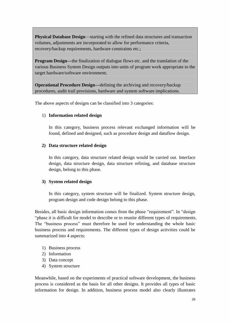
Physical Database Design—starting with the refined data structures and transaction
volumes, adjustments are incorporated to allow for performance criteria,
recovery/backup requirements, hardware constraints etc.;
Program Design—the finalization of dialogue flows etc. and the translation of the
various Business System Design outputs into units of program work appropriate to the
target hardware/software environment;
Operational Procedure Design—defining the archiving and recovery/backup
procedures, audit trail provisions, hardware and system software implications.
The above aspects of designs can be classified into 3 categories:
1) Information related design
In this category, business process relevant exchanged information will be
found, defined and designed, such as procedure design and dataflow design.
2) Data structure related design
In this category, data structure related design would be carried out. Interface
design, data structure design, data structure refining, and database structure
design, belong to this phase.
3) System related design
In this category, system structure will be finalized. System structure design,
program design and code design belong to this phase.
Besides, all basic design information comes from the phase “requirement”. In “design
“phase it is difficult for model to describe or to reunite different types of requirements.
The “business process” must therefore be used for understanding the whole basic
business process and requirements. The different types of design activities could be
summarized into 4 aspects:
1) Business process
2) Information
3) Data concept
4) System structure
Meanwhile, based on the experiments of practical software development, the business
process is considered as the basis for all other designs. It provides all types of basic
information for design. In addition, business process model also clearly illustrates

27
exchanged information. The sequence of whole design tasks can now be defined.
Corresponding models should be developed in each phase as results.
Business process:
Business process model, organizations model
Information:
Data model, information type model
Data concept:
Data structure model
System structure:
System structure model, hardware overview, software overview
4.2. Meta-model and transition rules
The tasks and sequence are the partial content of this model. The expression method,
the syntax of model and the meaning of notation which are responsible for presenting
the content, should be defined by the Meta model.
The Meta model is a model of model. It rules concern syntax, notification and
semantic of a model. The structure a meta-model is like the following8:
8
Univ.-Prof.Dr. Dimitris Karagiannis, Mag, Srdjdan Zivkovic: Method Engineering: basis of
integration in business engineering,
28
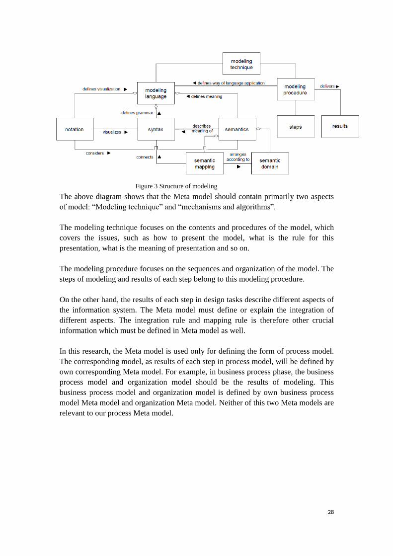
Figure 3 Structure of modeling
The above diagram shows that the Meta model should contain primarily two aspects
of model: “Modeling technique” and “mechanisms and algorithms”.
The modeling technique focuses on the contents and procedures of the model, which
covers the issues, such as how to present the model, what is the rule for this
presentation, what is the meaning of presentation and so on.
The modeling procedure focuses on the sequences and organization of the model. The
steps of modeling and results of each step belong to this modeling procedure.
On the other hand, the results of each step in design tasks describe different aspects of
the information system. The Meta model must define or explain the integration of
different aspects. The integration rule and mapping rule is therefore other crucial
information which must be defined in Meta model as well.
In this research, the Meta model is used only for defining the form of process model.
The corresponding model, as results of each step in process model, will be defined by
own corresponding Meta model. For example, in business process phase, the business
process model and organization model should be the results of modeling. This
business process model and organization model is defined by own business process
model Meta model and organization Meta model. Neither of this two Meta models are
relevant to our process Meta model.

29
4.3 The Research plan
The approach of developing design process model has three aspects:
1) Constant improvement for the process model
2) Integration rules and mapping rules development
3) Test of the process model performance by developing different system
models
This research approach is iterative process. The developed process model should be
tested and improved by developing corresponding system model in each step of this
process model.
The overall research approach is presented in following diagram:
Figure 4 research approach
The above diagram shows three layers of designing our process model. In the
meta-model layer, the concept, syntax and rules of design process model as well as
the whole system design and relevant tasks are defined. As results for each step in

30
process model, different system models should be presented in the third layers. In this
layer, the process model is utilized and applied. With this system models, the process
model can be evaluated and improved.
The purpose of this design process model is to provide software developers a
framework for designing Information system. Therefore, after developing this
information model, the design process model should have a capability to organize a
whole procedure of Information system development. It can also support designers to
finish design concepts by providing different patterns, methods and transformation
rules. This design process model is therefore significantly different from other
software development frameworks. It is more specialized to provide concrete methods
and codes to help developers rather than the basic functions such as organizing and
managing development cycles.
31
5. Overview of design process model
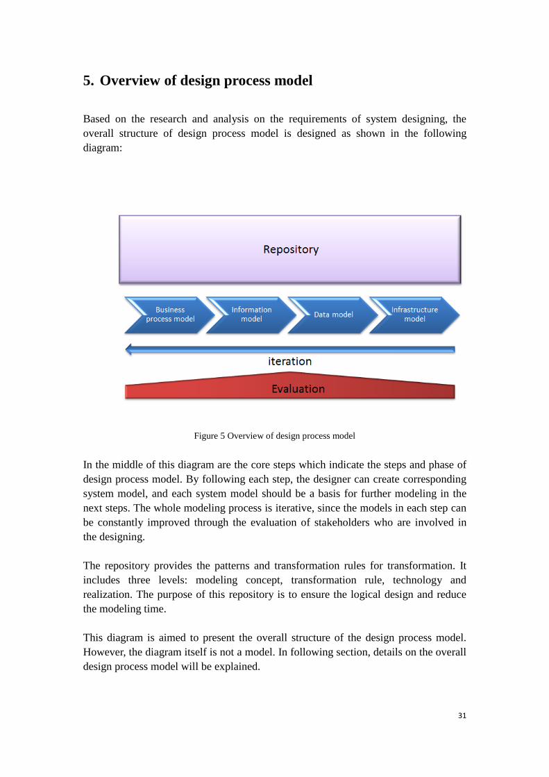
Based on the research and analysis on the requirements of system designing, the
overall structure of design process model is designed as shown in the following
diagram:
Figure 5 Overview of design process model
In the middle of this diagram are the core steps which indicate the steps and phase of
design process model. By following each step, the designer can create corresponding
system model, and each system model should be a basis for further modeling in the
next steps. The whole modeling process is iterative, since the models in each step can
be constantly improved through the evaluation of stakeholders who are involved in
the designing.
The repository provides the patterns and transformation rules for transformation. It
includes three levels: modeling concept, transformation rule, technology and
realization. The purpose of this repository is to ensure the logical design and reduce
the modeling time.
This diagram is aimed to present the overall structure of the design process model.
However, the diagram itself is not a model. In following section, details on the overall
design process model will be explained.
32
5.1. Process model
The process model is the core of the overall design process. It includes four steps,
which allows the designer to give a final design concept step by step. In this section,
the semantic and organization about process model will be explained.
As a type of model, the process model should include three major aspects that has
been explained in the last chapter. Therefore, in this chapter the UML-Model
language will be used to express the Meta model of the process model. The grammar
and notification for process model will also be defined.
5.1.1. The notification for process model
In process model, four types of meaning should be expressed:
1) Steps
2) flow chart
3) status
4) decision
1) steps
The steps mean activities and phrase in process model. It expresses what exactly must
be done immediately. Each step in process can also be divided into many sub steps.
2) Flow chart
Flow chart represents the sequence and order of steps. With flow chart, different steps
in process model can be organized. The logical meaning of derivation can also be
presented with flow chart.
3) Status
The status explains the state of modeling, which is useful to check logical
relationships and special requirements among different types of model. For example,
a business process model is established, which presents the requirements and
situations of business realities. However, due to the shortage of information, some
data, which are exchanged among distinguish business activities can not be defined.
In this case, undefined data can be remarked and in the “status”.
4) Decision

33
The decisions provide a possibility to decide whether the process of modeling can
progress to the next step. In the reality, all the needed information is not guaranteed to
be enough for modeling and designing. The quality of modeling must therefore be
tested and “decision” activity indicates whether the model is qualified for next
modeling.
The notifications about above meanings are listed in following table:
Table 1, the notifications of design process model
Notification explanation
<<Step>>
The steps mean activities and phrase in
process model
Step with
substep
Each step in process can contain many
sub steps
<<Status>>
The status explains the state of modeling.
That could help us to check the logical
relationship and special requirement
among the different types of model
decision
The decisions give us the possibility to
decide whether the process of modeling
moves to next step
Flo
w
Flow chart represents the sequence and
order of steps
By using UML Meta model, the grammars of process are defined.

34
Figure 6 Meta model for design process model
Each step can contain more than one sub step, but each sub step has only one super
step. Each class in the process model should be connected with the flow. The
“decision” can only be connected by flow, and in flow there is a criterion to decide
whether the model meets requirements and expectations of the designers. The “status”
describes the information on steps and provides criterions for decision.
This diagram shows the general structure of design process model. However, the
“status” and “decision” are not defined. The reason is simple: the concrete conditions
and status cannot be defined in a general manner. Therefore, it has to be
complemented later in the analysis of concrete cases.
According the Meta model and notation discussed above, the general process models
is as below:

35
Figure 7 design process model
36
Meanwhile, results that acquired in each step are different types of model. Therefore,
these models can be observed as an input for the next step and they are translated into
other types of model. A transition rule and mapping rule are then needed for this
transformation. These rules can be helpful to understand the logical and business
relationship among different aspects of designs in an easier way.
5.2. Model transformation approaches
The purpose of the design process model is to provide a complete and logical concept
for information system. Therefore, conducting different system models are required
for the final system structure concept. The procedure of the conduction can be seen as
a model to model transformation.
In addition, the quality of transformation influences the final results of design concept.
Appropriate transformation rules between models are therefore of significant
importance.
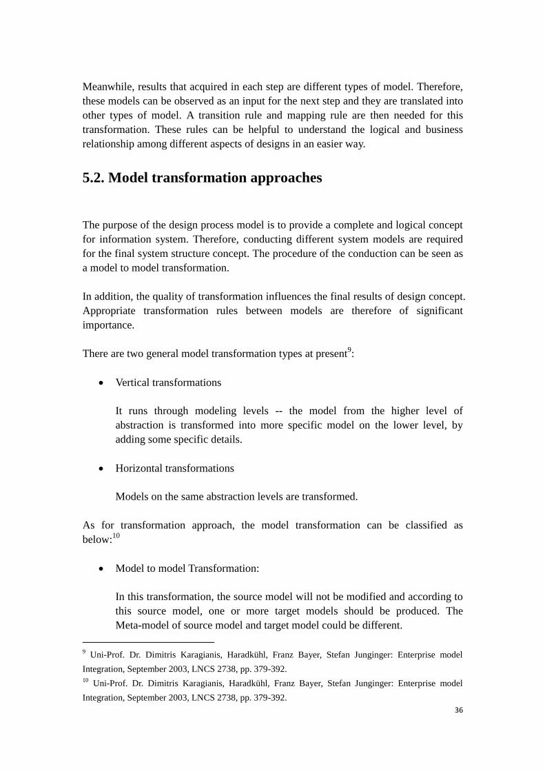
There are two general model transformation types at present9:
Vertical transformations
It runs through modeling levels -- the model from the higher level of
abstraction is transformed into more specific model on the lower level, by
adding some specific details.
Horizontal transformations
Models on the same abstraction levels are transformed.
As for transformation approach, the model transformation can be classified as
below:10
Model to model Transformation:
In this transformation, the source model will not be modified and according to
this source model, one or more target models should be produced. The
Meta-model of source model and target model could be different.
9 Uni-Prof. Dr. Dimitris Karagianis, Haradkühl, Franz Bayer, Stefan Junginger: Enterprise model
Integration, September 2003, LNCS 2738, pp. 379-392. 10
Uni-Prof. Dr. Dimitris Karagianis, Haradkühl, Franz Bayer, Stefan Junginger: Enterprise model
Integration, September 2003, LNCS 2738, pp. 379-392.
37
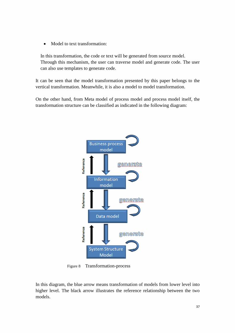
Model to text transformation:
In this transformation, the code or text will be generated from source model.
Through this mechanism, the user can traverse model and generate code. The user
can also use templates to generate code.
It can be seen that the model transformation presented by this paper belongs to the
vertical transformation. Meanwhile, it is also a model to model transformation.
On the other hand, from Meta model of process model and process model itself, the
transformation structure can be classified as indicated in the following diagram:
Figure 8 Transformation-process
In this diagram, the blue arrow means transformation of models from lower level into
higher level. The black arrow illustrates the reference relationship between the two
models.
38
Concrete meanings of transformation are like the following:
Business process model -> Business process model:
The transformation from Business process model to another business process
model indicates improvement of a new business process model, which belongs
to horizontal transformation. This transformation could execute through
modeling tools.
Business process model -> Information model:
This transformation is the first phase of the overall transformation procedure.
The necessary information will be retrieved from business process model and
transformed into information model by using UML class diagram. The
transformation rules and transformation approaches will be explained later in
following chapters.
Information Model -> Information Model
The transformation from information model to another information model
means improvement of an information model. That belongs to horizontal
transformation. This transformation could execute through modeling tools.
Information Model -> Data Model
This transformation is the second level in the whole transformation. The
information model will be reified. The information includes data will be
presented in model. And structure of data will be fixed.
Data Model -> Data model
The transformation from data model to another data model means
improvement of a data model. That belongs to horizontal transformation. This
transformation could execute through modeling tools.
Data Model -> System Structure Model
This transformation is the third level in the whole transformation. The system
structure model would be defined from data model. The system structure
model is final system design concept.
System Structure Model-> System Structure Model
39
In this transformation the system structure model will be improved.
5.2.1 Transformation Approach
Transformation is a complicated process and the whole transformation approach is
divided as below:
1) Transformation :
In this step, the model will be transformed automatically to other types of models by
using transformation technology such as QVT, domain-specific language (DSL) or
other transformation languages.11
Thus we can also define the general steps for model transformation12
1. Searching a model to identify appropriate elements transform.
2. Transforming elements.
3. The retention of tracing information recording which elements in a model are
related by the transformation to elements in other models.
4. Detecting updates in one model involved in the transformation and performing
relevant operations in the transformations other affected models.
2) refinement:
In this step, the transformed model will be manually complemented. Some necessary
information which cannot be transformed directly from previous model will be
complemented in this phase. The whole changing should be noticed in a monitoring
method.
3) Evaluation
The model should be evaluated after finishing transforming. The evaluation criticisms
are defined by vendors and stakeholders who attend this modeling. The results of
evaluation should be recorded and it is also a basis of “status”. The process model
provides some basic evaluation criticisms. The user can also add some customized
evaluation criteria according concrete modeling. But, for ensuring flexibility and
11
Uni-Prof. Dr. Dimitris Karagianis, Haradkühl, Franz Bayer, Stefan Junginger: Enterprise model
Integration, September 2003, LNCS 2738, pp. 379-392. 12
Model transformations and tool integration, Laurence Tratt,
http://tratt.net/laurie/research/publications/papers/tratt__model_transformations_and_tool_integration.p
df
40
coherence of modeling, the design process model doesn’t provide any concrete
evaluation methods.
5.3. The Repository
The Repository of design process model is a set of modeling concepts, modeling
patterns, transformation rules and concepts etc. The system designers or other users
can model and transform necessary distinguish models after the sequence of design
process model more easily. The whole design procedure will become more automatic.
The part of manual modeling and transforming would be reduced.
The Repository is however not a standard or definition which forces designers to use.
The Repository provides merely advices or concepts, which help system designer to
design the model and transform it more easily. It is very familiar in code
programming: each program language such as java, C#, PHP etc., provides countless
functions or methods for the realization of the complicated functions. It is
nevertheless the programmers who decide which and how to use those methods. The
Repository of design process model functions in the similar way: system designer can
decide what and how to use the methods from design process model‘s Repository for
their own modeling targets.
The Repository consists of three parts: Modeling concept, transformation rule and
technical issues:
41
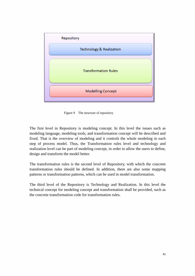
Figure 9 The structure of repository
The first level in Repository is modeling concept. In this level the issues such as
modeling language, modeling tools, and transformation concept will be described and
fixed. That is the overview of modeling and it controls the whole modeling in each
step of process model. Thus, the Transformation rules level and technology and
realization level can be part of modeling concept, in order to allow the users to define,
design and transform the model better.
The transformation rules is the second level of Repository, with which the concrete
transformation rules should be defined. In addition, there are also some mapping
patterns or transformation patterns, which can be used in model transformation.
The third level of the Repository is Technology and Realization. In this level the
technical concept for modeling concept and transformation shall be provided, such as
the concrete transformation code for transformation rules.
42
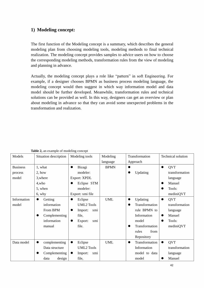
1) Modeling concept:
The first function of the Modeling concept is a summary, which describes the general
modeling plan from choosing modeling tools, modeling methods to final technical
realization. The modeling concept provides samples to advice users on how to choose
the corresponding modeling methods, transformation rules from the view of modeling
and planning in advance.
Actually, the modeling concept plays a role like “pattern” in soft Engineering. For
example, if a designer chooses BPMN as business process modeling language, the
modeling concept would then suggest in which way information model and data
model should be further developed. Meanwhile, transformation rules and technical
solutions can be provided as well. In this way, designers can get an overview or plan
about modeling in advance so that they can avoid some unexpected problems in the
transformation and realization.
Table 2, an example of modeling concept
Models Situation description Modeling tools Modeling
language
Transformation
Approach
Technical solution
Business
process
model
1, what
2, how
3,where
4,who
5, when
6, why
Bizagi
modeler:
Export: XPDL
Eclipse STM
modeler:
Export: xmi file
BPMN
Updating
QVT
transformation
language
Manuel
Tools:
mediniQVT
Information
model
Getting
information
From BPM
Complementing
information
manual
Eclipse
UML2 Tools
Import: xmi
file,
Export: xmi
file.
UML
Updating
Transformation
rule BPMN to
Information
model
Transformation
rules from
Repository
QVT
transformation
language
Manuel
Tools:
mediniQVT
Data model complementing
Data structure
Complementing
data design
Eclipse
UML2 Tools
Import: xmi
file,
UML Transformation
Information
model to data
model
QVT
transformation
language
Manuel
43
manual Export: xmi
file.
Transformation
rules from
Repository
Tools:
mediniQVT
Infrastructure
model
From data to
design
infrastructure
model
Eclipse
UML2 Tools
Import: xmi
file
Export: xmi file.
UML Transformation
Information
model to data
model
Transformation
rules from
Repository
QVT
transformation
language
Manuel
Tools:
mediniQVT
A simple example for modeling concept is presented in the above table. With
modeling tools, modeling language and transformation rules are defined in advance in
this table. The technical solution is also fixed.
The first Column “Situation description” describes the general situation about design
and modeling.
The “transformation approach” should include transformation rules, and steps in
modeling concept. Concrete contents about transformation rule for each
transformation will be explained in transformation rule level of Repository. In
modeling concept, only names of applied rule are listed.
Technical solutions define the concrete tools and technologies to implement the
transformation rule. The implementation should be present with code format.
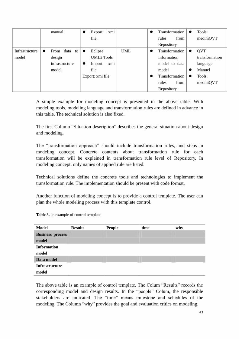
Another function of modeling concept is to provide a control template. The user can
plan the whole modeling process with this template control.
Table 3, an example of control template
Model Results People time why
Business process
model
Information
model
Data model
Infrastructure
model
The above table is an example of control template. The Colum “Results” records the
corresponding model and design results. In the “people” Colum, the responsible
stakeholders are indicated. The “time” means milestone and schedules of the
modeling. The Column “why” provides the goal and evaluation critics on modeling.
44
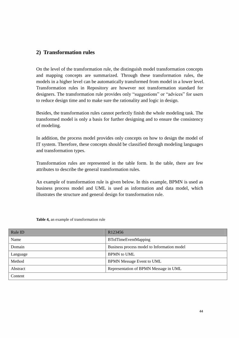
2) Transformation rules
On the level of the transformation rule, the distinguish model transformation concepts
and mapping concepts are summarized. Through these transformation rules, the
models in a higher level can be automatically transformed from model in a lower level.
Transformation rules in Repository are however not transformation standard for
designers. The transformation rule provides only “suggestions” or “advices” for users
to reduce design time and to make sure the rationality and logic in design.
Besides, the transformation rules cannot perfectly finish the whole modeling task. The
transformed model is only a basis for further designing and to ensure the consistency
of modeling.
In addition, the process model provides only concepts on how to design the model of
IT system. Therefore, these concepts should be classified through modeling languages
and transformation types.
Transformation rules are represented in the table form. In the table, there are few
attributes to describe the general transformation rules.
An example of transformation rule is given below. In this example, BPMN is used as
business process model and UML is used as information and data model, which
illustrates the structure and general design for transformation rule.
Table 4, an example of transformation rule
Rule ID R123456
Name BToITimeEventMapping
Domain Business process model to Information model
Language BPMN to UML
Method BPMN Message Event to UML
Abstract Representation of BPMN Message in UML
Content
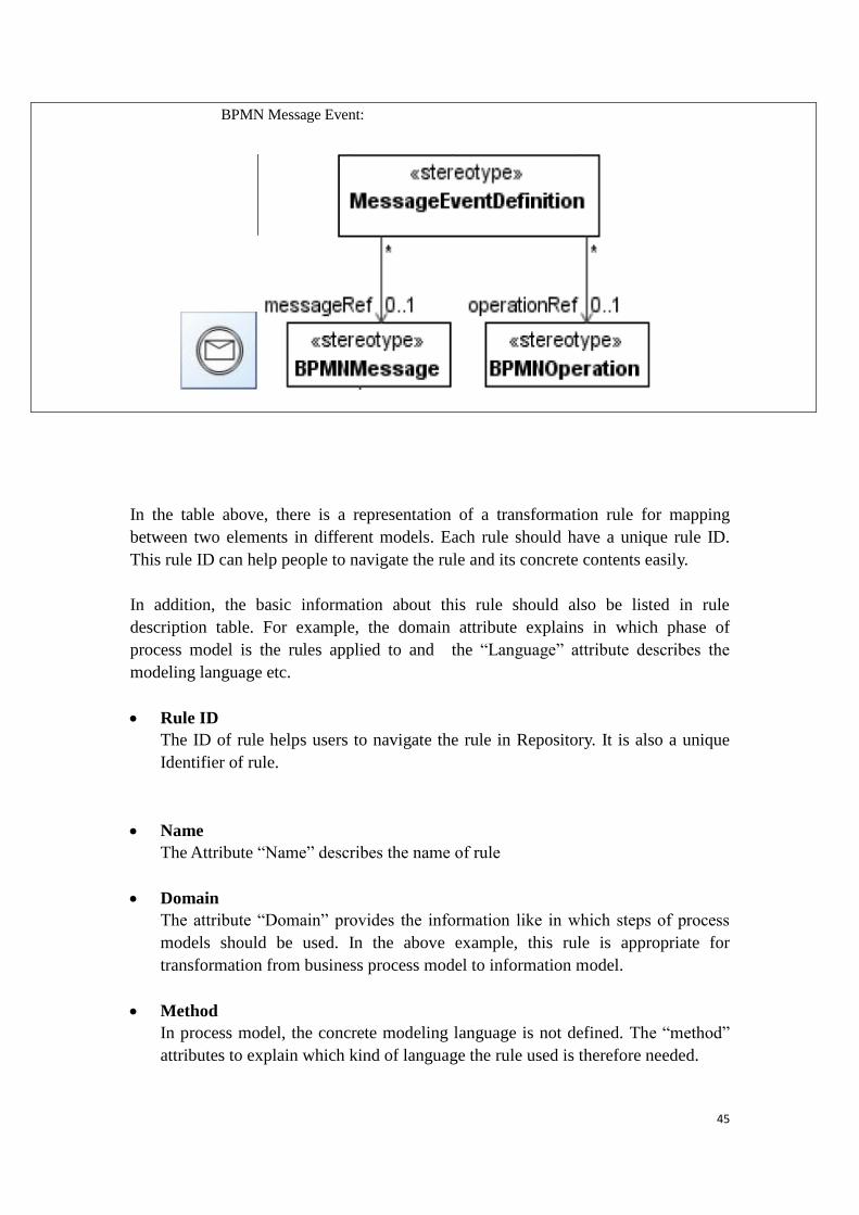
45
BPMN Message Event:
In the table above, there is a representation of a transformation rule for mapping
between two elements in different models. Each rule should have a unique rule ID.
This rule ID can help people to navigate the rule and its concrete contents easily.
In addition, the basic information about this rule should also be listed in rule
description table. For example, the domain attribute explains in which phase of
process model is the rules applied to and the “Language” attribute describes the
modeling language etc.
Rule ID
The ID of rule helps users to navigate the rule in Repository. It is also a unique
Identifier of rule.
Name
The Attribute “Name” describes the name of rule
Domain
The attribute “Domain” provides the information like in which steps of process
models should be used. In the above example, this rule is appropriate for
transformation from business process model to information model.
Method
In process model, the concrete modeling language is not defined. The “method”
attributes to explain which kind of language the rule used is therefore needed.
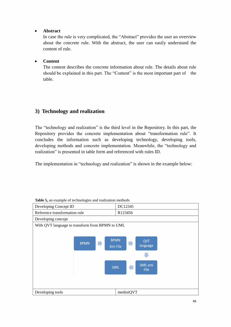
46
Abstract
In case the rule is very complicated, the “Abstract” provides the user an overview
about the concrete rule. With the abstract, the user can easily understand the
content of rule.
Content
The content describes the concrete information about rule. The details about rule
should be explained in this part. The “Content” is the most important part of the
table.
3) Technology and realization
The “technology and realization” is the third level in the Repository. In this part, the
Repository provides the concrete implementation about “transformation rule”. It
concludes the information such as developing technology, developing tools,
developing methods and concrete implementation. Meanwhile, the “technology and
realization” is presented in table form and referenced with rules ID.
The implementation in “technology and realization” is shown in the example below:
Table 5, an example of technologies and realization methods
Developing Concept ID DC12345
Reference transformation rule R123456
Developing concept
With QVT language to transform from BPMN to UML
Developing tools mediniQVT
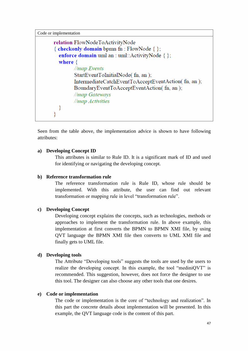
47
Code or implementation
Seen from the table above, the implementation advice is shown to have following
attributes:
a) Developing Concept ID
This attributes is similar to Rule ID. It is a significant mark of ID and used
for identifying or navigating the developing concept.
b) Reference transformation rule
The reference transformation rule is Rule ID, whose rule should be
implemented. With this attribute, the user can find out relevant
transformation or mapping rule in level “transformation rule”.
c) Developing Concept
Developing concept explains the concepts, such as technologies, methods or
approaches to implement the transformation rule. In above example, this
implementation at first converts the BPMN to BPMN XMI file, by using
QVT language the BPMN XMI file then converts to UML XMI file and
finally gets to UML file.
d) Developing tools
The Attribute “Developing tools” suggests the tools are used by the users to
realize the developing concept. In this example, the tool “mediniQVT” is
recommended. This suggestion, however, does not force the designer to use
this tool. The designer can also choose any other tools that one desires.
e) Code or implementation
The code or implementation is the core of “technology and realization”. In
this part the concrete details about implementation will be presented. In this
example, the QVT language code is the content of this part.
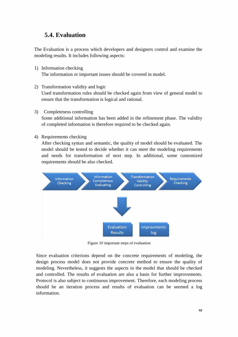
48
5.4. Evaluation
The Evaluation is a process which developers and designers control and examine the
modeling results. It includes following aspects:
1) Information checking
The information or important issues should be covered in model.
2) Transformation validity and logic
Used transformation rules should be checked again from view of general model to
ensure that the transformation is logical and rational.
3) Completeness controlling
Some additional information has been added in the refinement phase. The validity
of completed information is therefore required to be checked again.
4) Requirements checking
After checking syntax and semantic, the quality of model should be evaluated. The
model should be tested to decide whether it can meet the modeling requirements
and needs for transformation of next step. In additional, some customized
requirements should be also checked.
Figure 10 important steps of evaluation
Since evaluation criterions depend on the concrete requirements of modeling, the
design process model does not provide concrete method to ensure the quality of
modeling. Nevertheless, it suggests the aspects in the model that should be checked
and controlled. The results of evaluation are also a basis for further improvements.
Protocol is also subject to continuous improvement. Therefore, each modeling process
should be an iteration process and results of evaluation can be seemed a log
information.
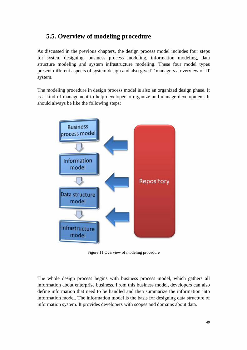
49
5.5. Overview of modeling procedure
As discussed in the previous chapters, the design process model includes four steps
for system designing: business process modeling, information modeling, data
structure modeling and system infrastructure modeling. These four model types
present different aspects of system design and also give IT managers a overview of IT
system.
The modeling procedure in design process model is also an organized design phase. It
is a kind of management to help developer to organize and manage development. It
should always be like the following steps:
Figure 11 Overview of modeling procedure
The whole design process begins with business process model, which gathers all
information about enterprise business. From this business model, developers can also
define information that need to be handled and then summarize the information into
information model. The information model is the basis for designing data structure of
information system. It provides developers with scopes and domains about data.

50
Data model is a more detailed information model. Data structure about information
system, database and business logic will be modeled in this model. It is the final
concept for IT data structure.
After defining data structure, the structure of whole system in infrastructure model
can be finalized.
The overall process is supported by the repository. The repository provides methods,
patterns, transformation rules to help developer to finish modeling and designing in a
more convenient way.
5.6. Summary of this chapter
In this part, the theory and concept of design process model for designing harbor
logistic planning system is explained. Generally, this design process model is a
framework for rational and logical designing information systems in enterprise. It
provides not only a method to organize and control software development, but also
defines the general transformation or mapping rule to ensure the consistency of
modeling.
The purpose of developing the process model is to avoid problems, which occurred in
designing and later updating. For example:
IT strategy cannot be implemented or executed in later design or implemented
phase.
Inconsistency in system design
Integration or updating problem
Black box developing
The Inspiration of design process model is based on the MDA and model
transformation in MDA. Some technologies, definitions and standards in MDA would
therefore be used to realize process model. Meanwhile, this process model is
considered as a complementation from CIM to PIM in MDA development. With this
design process model, the information in the real business world is easier to
implement in UML based PIM model.
Nevertheless, this process model is not like MDA which rules much coerciveness to
make sure the execution of final code. This design process model provides just some
suggestions and advices to reduce modeling time and make sure the flexibility of
design at the same time.

51
Repository is warehouse to conserve main transformation rules and concepts.
It is a library to ensure logical and rational design.
Process model is the core of the general structure and provides steps and
organization for development of system model.
Evaluation is influenced by designers, which are criticism for further
improvements.
52
6.Overview Architecture
Architecture is a blueprint; it shows how the overall system and different parts of
system interrelate will look like. The system architecture in this thesis is based on
“design process model”, which consists of five parts: business process architecture,
information architecture, information system architecture, data structures and final
system infrastructure architecture. These five aspects should be created in four phases
of design process model by using different system models and it should also be
implemented in further development process.
The design process model is different from overview architecture. It is only a
methodology to create and organize the system models. Relevant architecture of these
models can be finalized accordingly. The design process model is a method or tool
while architectures are a product of this design process model.
In this chapter, the general system architecture and relationship between design
process models will be explained. The usages of design process model and different
models to create information architecture will also be present in following chapters.

53
6.1. System Architecture
As discussed above, the system architecture is a blueprint of the overall system, which
describes system structures, technologies, and organization. Besides, the most
distinctive feature of design process model is that it can organize different aspects of
system architecture systematically. The system architecture in this thesis is therefore
based on system models from design process model and inherited from the logical
structure of system models.
The whole system architecture is illustrated as below:13
Figure 12 Information system architecture
This architecture is described in the book “information systems management in
practice” by Barbara c. Mcnurlin. The architecture in this thesis is based on the
architecture in this book and the design process model will be extended further
accordingly. It consists of five parts of system: business process architecture,
information architecture, information system architecture, data structures and final
system infrastructure architecture. These five aspects should be created in four phases
of design process model by using different system models and it should also be
implemented in further development process.
13
Barbara C. Mcnurlin, Ralph h.Sprague, JR.: Information systems management in practice 5 edition,
Upper Saddle River, NJ 07458
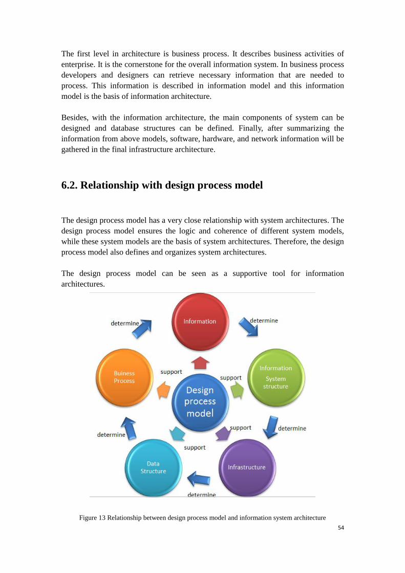
54
The first level in architecture is business process. It describes business activities of
enterprise. It is the cornerstone for the overall information system. In business process
developers and designers can retrieve necessary information that are needed to
process. This information is described in information model and this information
model is the basis of information architecture.
Besides, with the information architecture, the main components of system can be
designed and database structures can be defined. Finally, after summarizing the
information from above models, software, hardware, and network information will be
gathered in the final infrastructure architecture.
6.2. Relationship with design process model
The design process model has a very close relationship with system architectures. The
design process model ensures the logic and coherence of different system models,
while these system models are the basis of system architectures. Therefore, the design
process model also defines and organizes system architectures.
The design process model can be seen as a supportive tool for information
architectures.
Figure 13 Relationship between design process model and information system architecture
55
7. Business process model
After discussing the features of the overall design process model and the system
architectures, a practice phase will be addressed in the section. In this phase the
design process model will be utilized to organize modeling different system models
and provide corresponding modeling methods.
Information about business processes in Chinese harbor logistics is summarized in the
previous chapters. Each step and corresponding system models will be established in
following chapters. Furthermore, transformation rules, mapping approaches and
model researching will be elaborated in a precise manner during modeling. Through
the following examples, advantages and disadvantages of the design process model
will be discussed.
The business activities in Chinese harbor are complicated. They are not merely simple
transport and dispatch activities. Instead, the harbor is a marine and land logistic
center. It includes various tasks such as custom clearance, warehouse management,
dispatching, communicating with shipping agency, executing freight forwarding and
so on. Meanwhile, as a logistics center, the harbor should also have the ability of
coordinating the transport schedule with other land transport center or logistics center.
Accordingly, the information system of harbor is also rather multiplex to meet
requirements of various tasks. It is usually a huge system which includes OA system,
data warehouse system, EDI system, communicating interface, ERP system, GIS
system and so on.
Given the length of a master thesis, it is unrealistic to model the whole complete
Information system. In this paper, one of those business processes and relevant
information system is analyzed and modeled by using design process model. The core
meanings and thoughts of “design process model” are also elaborated.
In this chapter, the first step of design process model would be carried out. The
business process model simulated requirements and business realities for enterprise.
Therefore, business process can specific order the activities with clearly identified
inputs and outputs. The business process chosen by this paper is a core logistics
process of harbor. It contains the set-up of work schedule, marine logistics, warehouse
management and land logistic. In following chapters, details about these four topics
will be explained and the relevant transformation will be presented as well.

56
7.1. Business process modeling foundations used in this
thesis
The business process model is groundwork for the business process design. It
summarizes the information from “gathering requirement” phase and translates that
information into abstract and sustainable model.
The business process model simulates requirement and business realities for
enterprise, which allows the users to order the activities specifically with clearly
identified inputs and outputs. For example, a request from customer can be submitted
through web page and the corresponding results will be selected. Therefore, through
the business process model the designer and user can analyze the information, which
will be involved for business activities.
In addition, through simulation of business process in business process modeling tools,
the users and managers are able to find out the weak points or shortcomings in
business processes in order to improve the business process to make more business
values.
Considering the purpose of business process modeling, the optimizing business
process is not the major research focus in this thesis. The business processes to be
modeled will therefore be seemed as optimized business processes.
In this chapter, the first step of our process model – “business process modeling” will
be practically explained and applied into modeling a business process model for
harbor logistic center. In addition, from modeling of practical example, the “decision”
criterion in process model and the status of business process model will be
complemented. On the other hand, we could also clearly identify sub steps in business
process modeling. However, we cannot determine the transformation rules and
mapping rules before understanding the exact request of information model.
Therefore this part should be identified in next chapter.

57
7.2. The selection of modeling methods and tools
There are many available modeling tools and modeling methods for business process
modeling. Given the importance of business process model in business management,
IT developing and business process management, each organization and institute has
developed many different types of modeling to describe the business process. In
following table, the popular modeling techniques are listed14
:
Business Process Modeling Notation (BPMN)
Cognition enhanced Natural language Information Analysis Method
(CogNIAM)
Extended Business Modeling Language (xBML)
Event-driven process chain (EPC)
ICAM DEFinition (IDEF0)
Unified Modeling Language (UML), extensions for business process such as
Eriksson-Penker's
Selection of modeling technique for the business process modeling of this thesis is not
an easy task; since each modeling technique has its own technical pros and cons. The
technique should be applied cannot be selected merely from model’s features. The
general selecting process must meet following conditions:
Clearly defined the activities in business process model
Clearly defined the exchange information
Views from IT aspects
Easy understandable
The organizational structure
After comparing the modeling techniques, the Business Process Modeling Notation
(BPMN) is chosen for the business process modeling techniques in this thesis.
BPMN provides a number of advantages for modeling business processes compared to
the Unified Modeling Language (UML). Firstly, it offers a process flow modeling
technique which is more conducive in the way business analysis model.
Secondly, its solid mathematical foundation is designed to map business execution
languages, whereas UML is not. BPMN can map UML, and provide a more solid
business modeling front end to systems design with UML. The Business Process
Modeling Notation (BPMN) is a new standard to model business process flows and it
can also describe the corresponding web services. It is created by the Business Process
Management Initiative (BPMI). The first purpose of BPMN is to provide a notation that
is easily understandable by all business users. This includes the business analysts that
14
http://en.wikipedia.org/wiki/Business_process_modeling

58
create the initial drafts of the processes to the technical developers responsible for
implementing the technology that will perform those processes.15
Thirdly, the BPMN can also express XML languages that designed for the execution of
business processes with a common notation, such as BPEL4WS (Business Process
Execution Language for Web Services) and BPML (Business Process Modeling
Language). This feature is useful for further Information and data design.
Selection of tool is crucial. The user can choose whichever tools that he/she wishes. In
this thesis, the BizAgi process modeler is selected.16
15 Martin Owen and Jog Raj, Popkin: BPMN and Business Process Management,
http://www.omg.org/bpmn/Documents/6AD5D16960.BPMN_and_BPM.pdf
16 http://wiki.bizagi.com/en/index.php?title=Introduction

59
7.3. Core requirements of modeling
The goal of modeling the business process is to gather the basic business information
for Information system. The stakeholders’ requirements in IT aspect should focus on
the business activities. With this business process model, the blueprint of business
process with IS support should be illustrated and evaluated. Meanwhile, the system
designer from business process model can get basic knowledge about exchanged
information in business transaction. The requirements of business process model can
therefore be summarized into two aspects:
1) Business process modeling
The business process model is a type of model which should meet all requirements
of model. Clear physical steps, sequences and organizational structures are the
basic requirements of model. Meanwhile, roles and responsibilities of individuals,
decisions from workers and documents produced should also be considered in
model. Thus, as a first step of information system development, the link between
internal and external process, the parts of the process supported by IT systems and
the matched of the IT systems are very important aspects in business process
modeling.
2) Purpose of business process modeling
The purpose of model business process should be embodied with emphasis of
model. For example, if the purpose of business process modeling is to understand
the structure of human resources, the aspects such as organizational structures,
roles and responsibilities of individuals should be illustrated precisely in the model.
Other aspects of model can be simplified.
60
7.4. Important business process modules in harbor
environments
As noted in the above chapter, the overall original intention for this thesis is to design
a harbor-logistics-oriented IS design process model. Therefore, the harbor logistics
business is taken as an example throughout the whole modeling phase.
The business activities and process of harbor logistic consist of four main aspects:
1) Setting up work schedules
2) Marine transports and logistics
3) Land transports and logistics
4) Warehouse tasks
The harbor company firstly makes a company’s general business schedule for a
season. This schedule includes all information about the shipment, cargos and ports.
Meanwhile, this schedule assigns the basic transport and depot tasks for each working
team. After discussion with working teams, working units or responsible managers,
the schedule should be improved and complemented.
The completed schedule will be assigned to each corresponding working unit. The
working unit must make their own work plans after the assignment and carry out the
Marine and land transport tasks.
The warehouse tasks should depend on the situation of marine shipment and land
transport, in case a replacement of the cargo is needed.
1) Making work schedules
In a harbor, there are two levels of organizations to manage the business operation.
One is Harbor Co. Group, the other one is Port Company.
The Harbor Co. Group is usually a holding company that runs the business such as
harbor constructions, harbor developments, investments, and logistics etc. The main
business responsibility of Port Company is port logistics. Therefore, according to the
requirements of the enterprise, the harbor Co. Group should firstly give the port
company information about shipment and cargo. At the same time, after receiving the
information from Co. Group, the port company should make work schedules for one
business season. After discussing with responsible departments, the work schedule
and work assignment for whole harbor will be issued.

61
With this work schedule, the relevant information of work schedule will be saved in a
backup in Harbor Co. Group. The information will also be reported forward to
relevant official government later.
The business process of the work schedule is illustrated in the following model:

62
Figure 14 business process of making work schedule

63
2) Shipment departure and arrival
Figure 15 Ship departure and arrival part 1
The marine transport and logistics from the port’s point of view mainly contains two
processes. One is ship arrival; the other one is ship departure.
Seen from the above model, the arrive process is: firstly, the towage from port reports
to the port dispatcher about the status and position of towage. The towage then gets
the information for port dispatchers such as berth document, ship information and
cargo information. According to this information the towage arranges a work plan
which issues the details of towing and sends to dispatcher. After summarizing all
information from different towages, the towage will be assigned for a towing work by
a dispatcher, the ship and towage can communicate with each other during the towing
process. The towing work is finished when the ship reaches the planned port
successfully.
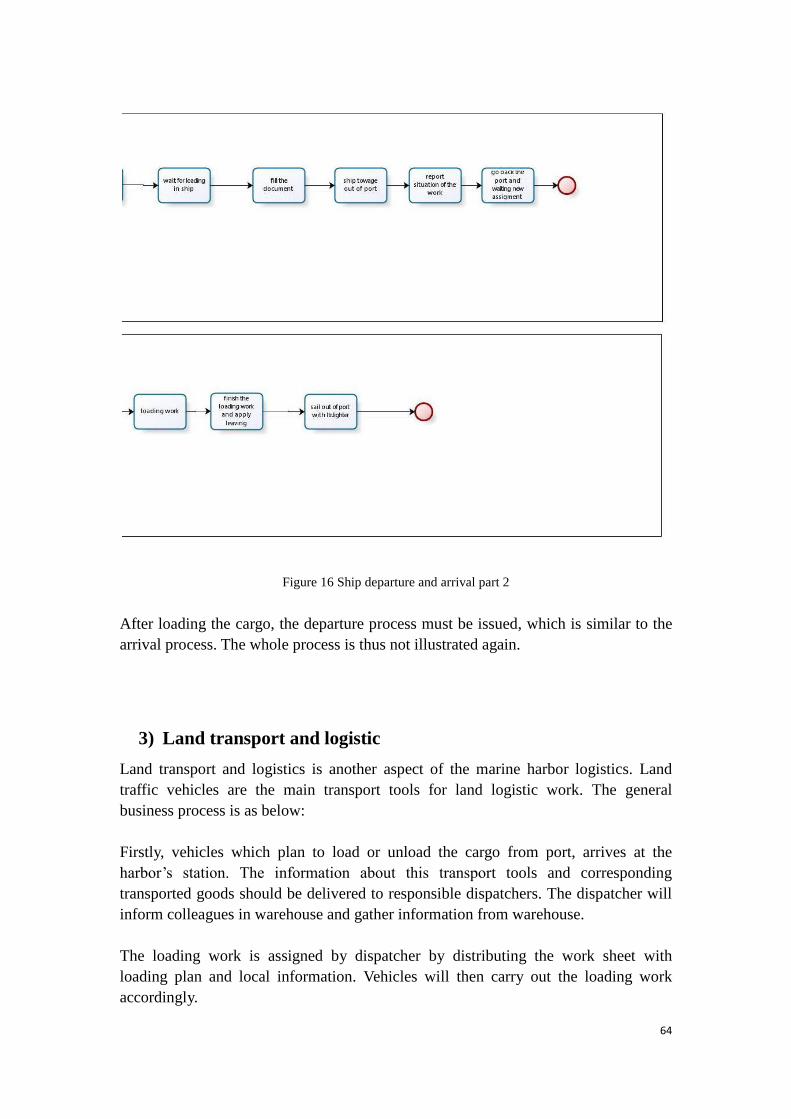
64
Figure 16 Ship departure and arrival part 2
After loading the cargo, the departure process must be issued, which is similar to the
arrival process. The whole process is thus not illustrated again.
3) Land transport and logistic
Land transport and logistics is another aspect of the marine harbor logistics. Land
traffic vehicles are the main transport tools for land logistic work. The general
business process is as below:
Firstly, vehicles which plan to load or unload the cargo from port, arrives at the
harbor’s station. The information about this transport tools and corresponding
transported goods should be delivered to responsible dispatchers. The dispatcher will
inform colleagues in warehouse and gather information from warehouse.
The loading work is assigned by dispatcher by distributing the work sheet with
loading plan and local information. Vehicles will then carry out the loading work
accordingly.

65
The dispatcher will also have a work record after finishing loading work is finished ,
which must be confirmed by other business partners or agencies, such as ship agency,
cargo agency, and the custom.

66
Figure 17 Land transport and logistics part 1
Figure 18 Land transport and logistics part 2
4) Warehouse task
The warehouse task includes all container transport activities, such as the
connect-point inside the warehouse between the land logistics and marine logistics.
The purpose of warehouse tasks is to avoid the shortage of warehouse room and to
manage the cargos in warehouse more efficiently. Concrete activities are as below:
The warehouse manager coordinates cargos positions, according to the storage plan
and transport plan. If he finds the situation such as overtime storage or unpunctual
transport, he reports to central dispatcher and also adjusts the position of cargos to
make sure enough room in the warehouse to keep merchandises in plan. Meanwhile,
the manager also needs to assign the worksheet to responsible workers and receive the
situation reports from workers.
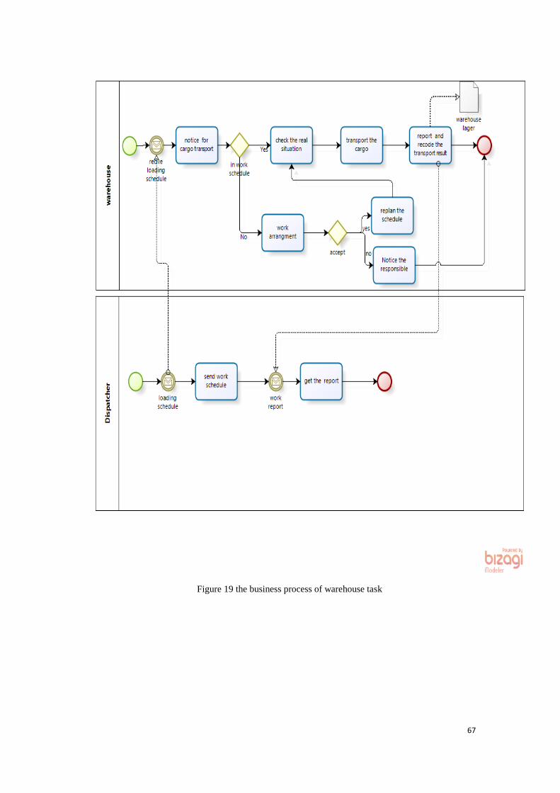
67
Figure 19 the business process of warehouse task

68
7.5. Summary of this chapter
In this chapter the business process model is researched and modeled. The business
process model is the first model in design process model; the business process model
can be seen as information gathering phase in the whole design process model. The
important business activities and exchanged information between business partners is
already modeled in this part. In the example in this chapter, the whole cargo transport
inside of harbor is abstracted into a business process model. With this business
process model, the designer can have an overview of the situation with business
partners and stakeholders in cargo transport.
However, the business process model provides designer with a basic “platform” or
“background”. It is like a “domain” or “scope” to restrict the explanation of the IT
system. The business process model is however not able to provide the system
designer with more structural information which can direct applied in IT system. The
designer therefore needs to transform the Business process model into information
model with further design by following steps of design process model.
The business process modeling in design process model has minor difference from
general business process model: the business process model in design process model
modeled is more information-oriented than normal business process model. The
emphasis of modeling should be in a range of information events, exchanged
information, information relevant business activities and partners. The irrelevant
activities such as hand work, carrying cargo should not be playing an important role.
69
8. Information model
Information modeling is the second step in the process model. The main purpose of an
Information model is to model the managed objects at conceptual level. It should be
independent of any specific implementation or situation. Therefore, the information
model should also hide all protocol or implementation details to ensure this
“independent”. But, the necessary relationship between managed objects should be
defined.17
In our case, the information model should be transformed from previous business
process model. So the managed objects in our information model are all exchanged
and relevant information in business process model. But another question we must
consider before researching transformation between business process model and
information model is: how the information model should be expressed?
The representation method of information model is various. It can be defined by using
a formal language or a semi-formal structured language. But through class diagrams
of the Unified Modeling Language (UML) to present the information model is very
popular today. The reason is very simple: UML is standardized by the Object
Management Group (OMG) and UML presents the advantage of being widely
adopted in the industry. In our case, the information modeling is the basis of further
data modeling. Using UML to describe the data model is first choice for every
programmer or system implementer. Therefore, using UML to model the information
model can avoid complicated work in transformation for different types of model.
Therefore, we could treat the transformation between business process model and
information model as BPMN to UML. But it is very important that this transformation
is not 1:1 transformation, since only information element in business process model
should be retrieved.
17 A. Pras, J. Schoenwaelder ,On the Difference between Information Models and Data Models,
http://www.ietf.org/rfc/rfc3444.txt
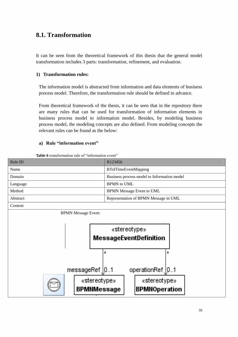
70
8.1. Transformation
It can be seen from the theoretical framework of this thesis that the general model
transformation includes 3 parts: transformation, refinement, and evaluation.
1) Transformation rules:
The information model is abstracted from information and data elements of business
process model. Therefore, the transformation rule should be defined in advance.
From theoretical framework of the thesis, it can be seen that in the repository there
are many rules that can be used for transformation of information elements in
business process model to information model. Besides, by modeling business
process model, the modeling concepts are also defined. From modeling concepts the
relevant rules can be found as the below:
a) Rule “information event”
Table 6 transformation rule of “information event”
Rule ID R123456
Name BToITimeEventMapping
Domain Business process model to Information model
Language BPMN to UML
Method BPMN Message Event to UML
Abstract Representation of BPMN Message in UML
Content
BPMN Message Event:

71
b) Data exchange
Table 7 Transformation rule of “Data exchange”
Rule ID R123457
Name BToIDataMapping
Domain Business process model to Information model
Language BPMN to UML
Method BPMN data to UML
Abstract transformation of exchanging data into UML
Class
Content
BPMN Data :
Data Objects are Artifacts that are used to show how data and documents are used within a Process
Data Objects can be used to define inputs and outputs of activities
Data Objects can be given a “state” that shows how a document may be changed or updated within the
Process
transformation to UML:
Data Objects is a class in information model
Data class has attributes: name, reference, contents and input, output
Attributes input and output define the flow of data
Data class can connect other data class.
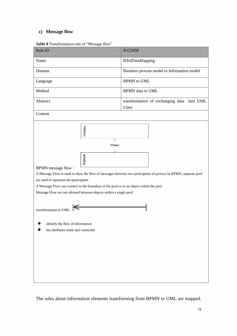
72
c) Message flow
Table 8 Transformation rule of “Message flow”
Rule ID R123458
Name BToIDataMapping
Domain Business process model to Information model
Language BPMN to UML
Method BPMN data to UML
Abstract transformation of exchanging data into UML
Class
Content
BPMN message flow :
A Message Flow is used to show the flow of messages between two participants of process In BPMN, separate pool
are used to represent the participants
A Message Flow can connect to the boundary of the pool or to an object within the pool
Message Flow are not allowed between objects within a single pool
transformation to UML:
identify the flow of information
has attributes name and constraint
The rules about information elements transforming from BPMN to UML are mapped.
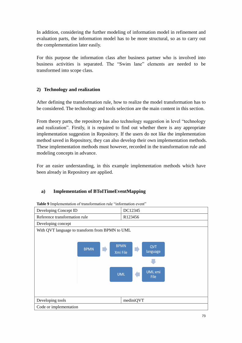
73
In addition, considering the further modeling of information model in refinement and
evaluation parts, the information model has to be more structural, so as to carry out
the complementation later easily.
For this purpose the information class after business partner who is involved into
business activities is separated. The “Swim lane” elements are needed to be
transformed into scope class.
2) Technology and realization
After defining the transformation rule, how to realize the model transformation has to
be considered. The technology and tools selection are the main content in this section.
From theory parts, the repository has also technology suggestion in level “technology
and realization”. Firstly, it is required to find out whether there is any appropriate
implementation suggestion in Repository. If the users do not like the implementation
method saved in Repository, they can also develop their own implementation methods.
These implementation methods must however, recorded in the transformation rule and
modeling concepts in advance.
For an easier understanding, in this example implementation methods which have
been already in Repository are applied.
a) Implementation of BToITimeEventMapping
Table 9 Implementation of transformation rule “information event”
Developing Concept ID DC12345
Reference transformation rule R123456
Developing concept
With QVT language to transform from BPMN to UML
Developing tools mediniQVT
Code or implementation
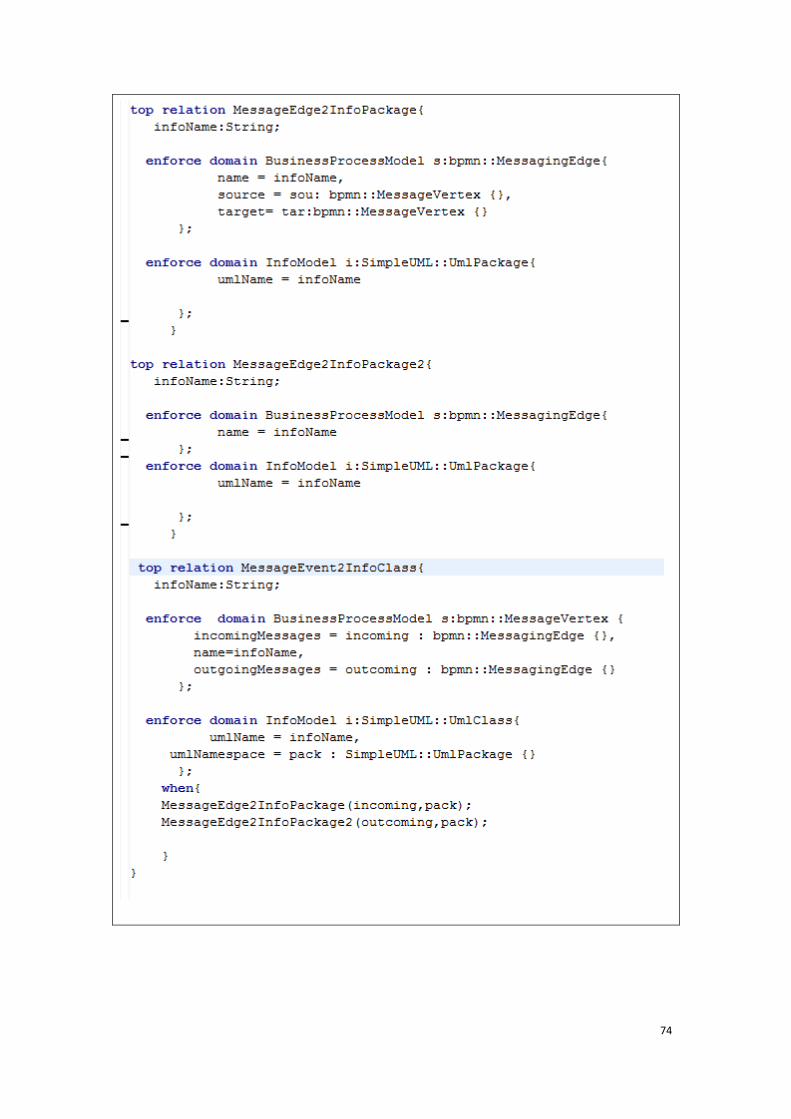
74
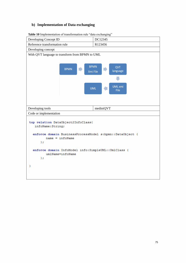
75
b) Implementation of Data exchanging
Table 10 Implementation of transformation rule “data exchanging”
Developing Concept ID DC12345
Reference transformation rule R123456
Developing concept
With QVT language to transform from BPMN to UML
Developing tools mediniQVT
Code or implementation

76
3) Results of first transformation:
After defining transformation rule and determining the implementation approach, the
transformation can be executed. From the part of theory, the general transformation
steps are like the below18
:
1. Searching a model to identify appropriate elements to transform.
2. Transforming elements.
3. The retention of tracing information recording which elements in a model are
related by the transformation to elements in other models.
4. Detecting updates in one model involved in the transformation and performing
relevant operations in the transformations other affected models.
The first version of Information model is like the following:
a) Making work schedules
Figure 20 Information model in aspect of “Making work schedules”
18
Enterprise Model Integration by Uni-Prof.Dr.Dimitris Karagiannis, Mag.Srdjan Zivkovic

77
From model above, it can be seen that the first information model has two packages.
These two packages are mapped from swim lane in business process model. They also
mean the two business partners, who exchange business information. In these two
packages, there are many classes; they are transformed from information or message
items of business process model. The association lines among different classes mean
information exchange approaches. In above model, “work report” and “work schedule”
is information which must be processed by both site of business partner, so the classes
“work report” and “work schedule” should locate in both package. Information such
as ship information, job slip is only processed inside of Port Company. Therefore,
they are located only in package “Port Company”.
This model is only a simple and preliminary draft. It transforms directly from business
process model and describes the general information items and their relationships in
business process model. That is basis for further modeling and refining.
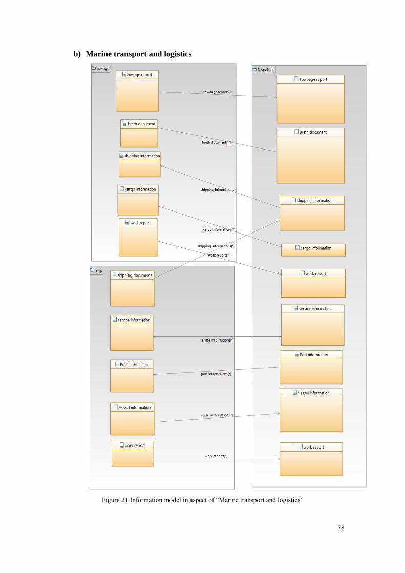
78
b) Marine transport and logistics
Figure 21 Information model in aspect of “Marine transport and logistics”
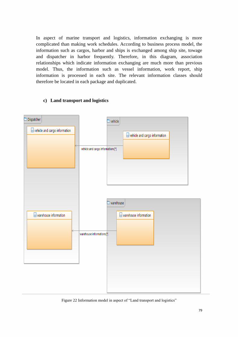
79
In aspect of marine transport and logistics, information exchanging is more
complicated than making work schedules. According to business process model, the
information such as cargos, harbor and ships is exchanged among ship site, towage
and dispatcher in harbor frequently. Therefore, in this diagram, association
relationships which indicate information exchanging are much more than previous
model. Thus, the information such as vessel information, work report, ship
information is processed in each site. The relevant information classes should
therefore be located in each package and duplicated.
c) Land transport and logistics
Figure 22 Information model in aspect of “Land transport and logistics”

80
Land transport is another side of whole harbor logistics. The information that
has to be processed in harbor site is a substantial amount. The information
model in this aspect is therefore simple. Dispatcher receives all information
about warehouse and vehicle and according this information to arrange
transport to vehicles.
d) Warehouse task
Figure 23 warehouse task
81
According to the transformation rule, in aspect of warehouse management
information such as warehouse information, work report and loading information can
be retrieved, which do not include all the information of warehouse management.
However, respecting logical transformation, missing information should be added in
refinement phase.
After transformation, the information elements in BPMN are already converted into
UML classes. However, from the above diagrams, a situation is noticeable: the
converted classes are redundant and always repeated in different packages. Therefore,
a further improvement of this information model is needed in the refinement phase.
8.2. Refinement
The second step of modeling information model is refinement. The transformed
information model will be complemented and newly designed. The completed
information model should be presented in this part.
The refinement phase is different from transformation phase: the transformation phase
ensured the logic and ration of the modeling. However, it could ignore the semantic
feature of a model. Besides, 1:1 transformation is not able to find out the some
implicated meaning of a model. For example, in harbor logistic system, the weather
and water condition is also very important information for harbor logistic planning
system. However, this information may not be presented in business process model.
Therefore, this “refinement” part is needed to complete the information model.
In complementing and sorting information model, three aspects must be paid
attention:
1) The structure and logical relationship among classes, attributes and so on.
2) Complementing the implicated meaning of model
3) Correction of mistake in transformation phase.
Besides, the refinement should be also declared and noticed in model, which allow
other design partners to understand the meaning of changing.
A table for monitoring is suggested for this purpose:
Table 11 a suggested monitor table
activities description People time why
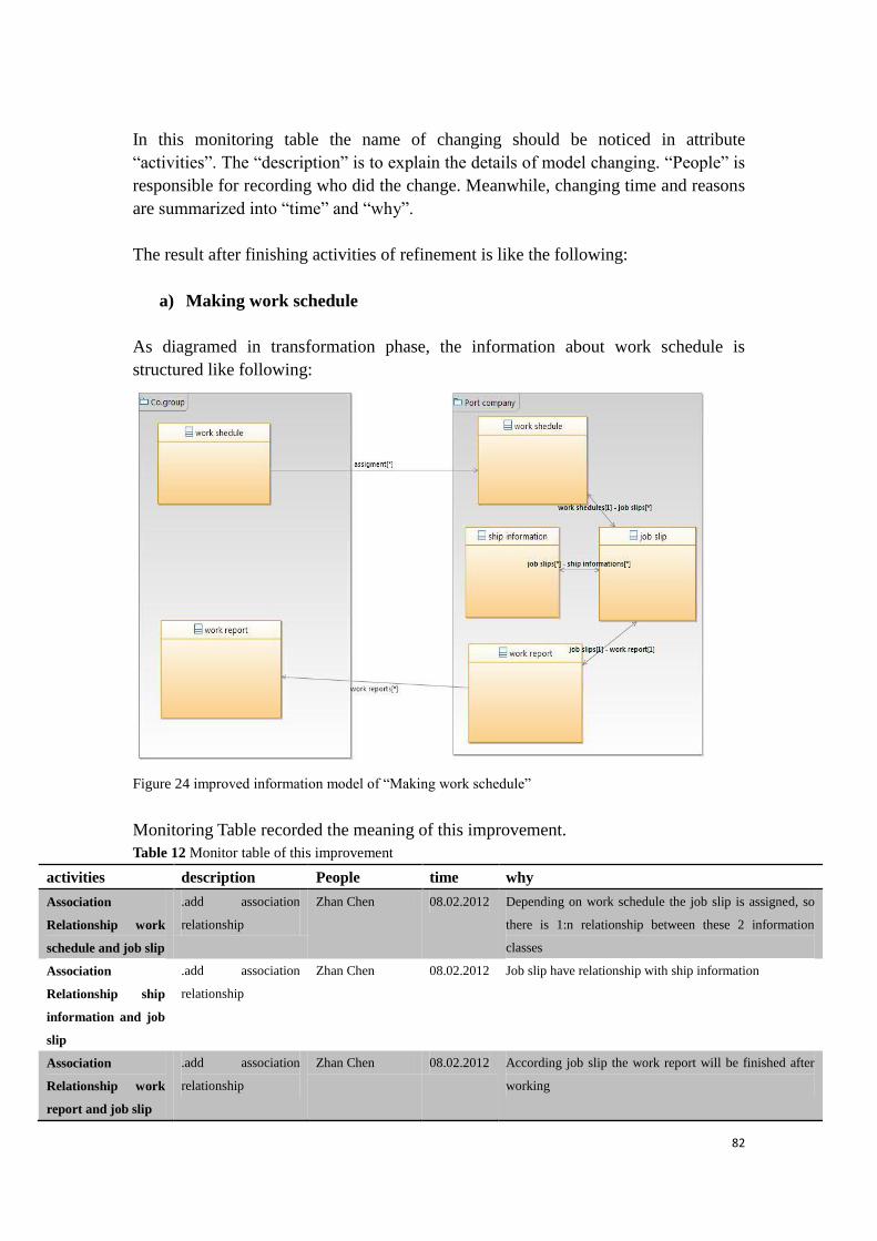
82
In this monitoring table the name of changing should be noticed in attribute
“activities”. The “description” is to explain the details of model changing. “People” is
responsible for recording who did the change. Meanwhile, changing time and reasons
are summarized into “time” and “why”.
The result after finishing activities of refinement is like the following:
a) Making work schedule
As diagramed in transformation phase, the information about work schedule is
structured like following:
Figure 24 improved information model of “Making work schedule”
Monitoring Table recorded the meaning of this improvement.
Table 12 Monitor table of this improvement
activities description People time why
Association
Relationship work
schedule and job slip
.add association
relationship
Zhan Chen 08.02.2012 Depending on work schedule the job slip is assigned, so
there is 1:n relationship between these 2 information
classes
Association
Relationship ship
information and job
slip
.add association
relationship
Zhan Chen 08.02.2012 Job slip have relationship with ship information
Association
Relationship work
report and job slip
.add association
relationship
Zhan Chen 08.02.2012 According job slip the work report will be finished after
working

83
Seen from the table above, in this refinement phase, the relationships among classes
are defined. The structure of this information model is more detailed. Meanwhile,
from monitoring table the reason of improving this part of model and who did it can
be seen. Therefore, the whole refinement phase can be monitored and controlled.

84
b) Marine transport and logistics
Figure 25 improved information model of “Marine transport and logistics”

85
Monitoring Table recorded the meaning of this improvement.
Table 13 Monitor table of improvement
activities description People time why
Business
information
class
add super class
Business information
class
Zhan Chen 08.02.2012 Classify the information type
Generalization
relationship among
information classes
and business
information class
add generalization
relationship
Zhan Chen 08.02.2012 Classify the information type
Report class add super class
report class
Zhan Chen 08.02.2012 Classify the information type
Generalization
relationship among
report classes and
report class
add generalization
relationship
Zhan Chen 08.02.2012 Classify the information type
document class add super class
document class
Zhan Chen 08.02.2012 Classify the information type
Generalization
relationship among
documents classes
and document class
add generalization
relationship
Zhan Chen 08.02.2012 Classify the information type
Considering the complexity of information classes in this model, in the refinement
phase, classes in this model are summarized and classified after type of information.
This generalization process also has been recorded in monitoring table. Therefore,
from monitor table, it can be seen that classes in this model are generalized into three
super classes: report, business information and documents.
c) Land transport and logistics
As discussed in the transformation phase, because of the gap between transformation
rules and concrete situation, some information items or information exchanging
processes have been not mapped and transformed in information model. Therefore, in
this phase, those items and processes should be completed.
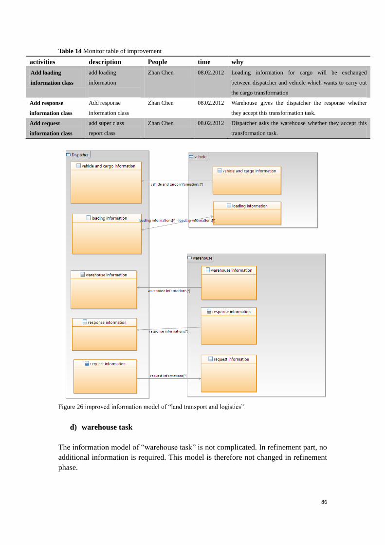
86
Table 14 Monitor table of improvement
activities description People time why
Add loading
information class
add loading
information
Zhan Chen 08.02.2012 Loading information for cargo will be exchanged
between dispatcher and vehicle which wants to carry out
the cargo transformation
Add response
information class
Add response
information class
Zhan Chen 08.02.2012 Warehouse gives the dispatcher the response whether
they accept this transformation task.
Add request
information class
add super class
report class
Zhan Chen 08.02.2012 Dispatcher asks the warehouse whether they accept this
transformation task.
Figure 26 improved information model of “land transport and logistics”
d) warehouse task
The information model of “warehouse task” is not complicated. In refinement part, no
additional information is required. This model is therefore not changed in refinement
phase.

87
8.3. Important points for evaluation
The evaluation part is the controlling and monitoring phase of modeling. In this part,
the whole finished model is evaluated and controlled. Some advice of other
stakeholders such as business managers, workers or other designers should be also
listened or followed. After accumulating these advices, the modeling work would
come back to the refinement phase to achieve further improvement. This iteration can
not only ensure the quality of model transformation, but also help designers to take all
factors of modeling into consideration.
The business process Repository does not provide concrete methods to evaluate the
quality of model. However, the aspects of evaluation are already defined. They are
like the following:
1) Information checking
The information or important issues should be covered in model.
2) Transformation validity and logic
The used transformation rule should be checked again from view of general result
to determine whether it is logical.
3) Completeness controlling
Some additional information has been added in refinement phase. It is therefore
needed to check the validity of completed information again.
4) Requirements checking
After checking of syntax and semantic, the quality of model should be evaluated.
The model should be tested whether it can meet the modeling requirements and
needs for transformation in next step. In additional, some customized requirements
should be also checked.
The concrete evaluation process should base on the above aspects. The user can also
add some customized evaluation points to complete the whole evaluation. The results
of evaluation can be a check list or a report. These results must be a basis of further
improvements.
Here is a simple example which uses table and check list to evaluate model.
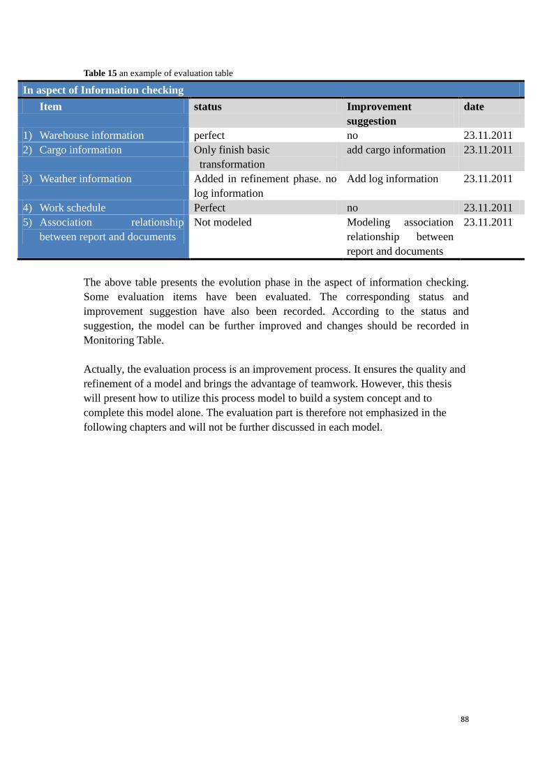
88
Table 15 an example of evaluation table
In aspect of Information checking
Item status Improvement
suggestion
date
1) Warehouse information perfect no 23.11.2011
2) Cargo information Only finish basic
transformation
add cargo information 23.11.2011
3) Weather information Added in refinement phase. no
log information
Add log information 23.11.2011
4) Work schedule Perfect no 23.11.2011
5) Association relationship
between report and documents
Not modeled Modeling association
relationship between
report and documents
23.11.2011
The above table presents the evolution phase in the aspect of information checking.
Some evaluation items have been evaluated. The corresponding status and
improvement suggestion have also been recorded. According to the status and
suggestion, the model can be further improved and changes should be recorded in
Monitoring Table.
Actually, the evaluation process is an improvement process. It ensures the quality and
refinement of a model and brings the advantage of teamwork. However, this thesis
will present how to utilize this process model to build a system concept and to
complete this model alone. The evaluation part is therefore not emphasized in the
following chapters and will not be further discussed in each model.

89
8.4. Summary of this chapter
Information modeling is the second step in the process model. The main purpose of an
Information model is to model the managed objects at conceptual level. It should be
independent of any specific implementation or situation. Therefore, the information
model should also hide all protocol or implementation details to ensure this
“independent”. However, the necessary relationship between managed objects should
be defined
In this chapter the information model is transformed from the business process model.
However, this transformation is not 1:1 transformation. Only information of relevant
elements in business process model have been retrieved and redefined after UML rule.
The automatic transformation could not meet all requirements of information model;
therefore, in the second phase this model must be complemented. The process of
refinement is recorded as well.
In addition, the transformation happens not only between different models, but also
inside of model. The disadvantages may be found after evaluating. Therefore,
updating or model transforming from old version to new version is necessary, which
is also a main purpose for evaluation.

90
9. Data Model
Data modeling is the third step in design process model. In this step the retrieved
information will be further developed and structured. The information will be
converted into concrete data which should be processed later.
Actually, the data model (DM) is an abstract model which describes all business or
organization relevant data. These data will be stored and processed in business IT
system.
Therefore, a data model determines all details about processed data, which is not only
a model, but also a plan that the system developer can use for database
implementation.
The relationship between data model and information model (IM) is very close. The
data model is defined at a lower level of abstraction and includes many details.
Information model always provides a conceptual/abstract model.
Figure 27 differences between data model and information model
The relationship between an IM and DM is shown in the Figure above. Since
conceptual models can be implemented in different ways, multiple DMs can be derived
from a single IM.19
19
A. Pras,J. Schoenwaelder ,On the Difference between Information Models and Data Models, by
http://www.ietf.org/rfc/rfc3444.txt
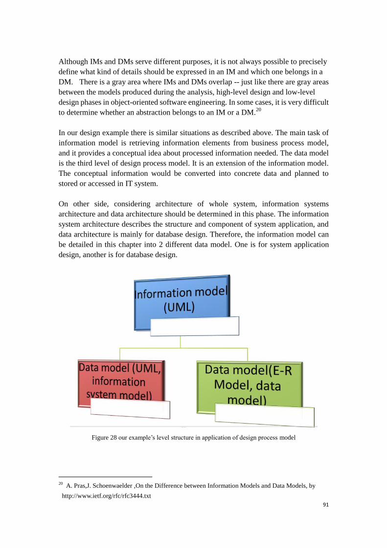
91
Although IMs and DMs serve different purposes, it is not always possible to precisely
define what kind of details should be expressed in an IM and which one belongs in a
DM. There is a gray area where IMs and DMs overlap -- just like there are gray areas
between the models produced during the analysis, high-level design and low-level
design phases in object-oriented software engineering. In some cases, it is very difficult
to determine whether an abstraction belongs to an IM or a DM.20
In our design example there is similar situations as described above. The main task of
information model is retrieving information elements from business process model,
and it provides a conceptual idea about processed information needed. The data model
is the third level of design process model. It is an extension of the information model.
The conceptual information would be converted into concrete data and planned to
stored or accessed in IT system.
On other side, considering architecture of whole system, information systems
architecture and data architecture should be determined in this phase. The information
system architecture describes the structure and component of system application, and
data architecture is mainly for database design. Therefore, the information model can
be detailed in this chapter into 2 different data model. One is for system application
design, another is for database design.
Figure 28 our example’s level structure in application of design process model
20
A. Pras,J. Schoenwaelder ,On the Difference between Information Models and Data Models, by
http://www.ietf.org/rfc/rfc3444.txt

92
9.1. Types of data models
As discussed in introduction, in this phase, two types of data model should be
conducted from information model for information system architecture and data
architecture. These two architectures can be described with information system model
and data model. Meanwhile, the object-orient programming language is now a main
current to implement design concepts. Entity-relation table is the basis of designing
database. Therefore, UML is used for further information system modeling and E-R
model for database model
Considering the UML is a modeling method of information model in our example,
UML can be used as the modeling method for information systems model. There are
two reasons:
1) Avoid missing of semantic meaning
When a model is transformed to another model, the missing of semantic meaning
would definitely happen. Therefore, if the same method is used to model, the set
of missing of meaning could be reduced. Meanwhile, the volume of work
transforming can also be reduced.
2) Traceability of model
By using same modeling method, the consistence of logic and ration can be
ensured. Thus, it is much easier for the designers to trace the source model, if they
cannot understand some meaning of data model.
The designers can choose any modeling method they want. This thesis will present
only the relationship between data model and information model in design process
model. The discussion about feature of models and modeling is not the emphasis and
will not be explained further.
The tools which have already used in transformation phase of “business process
model to information model” as modeling and transformation tool for “information
model to data model” can therefore be utilized.
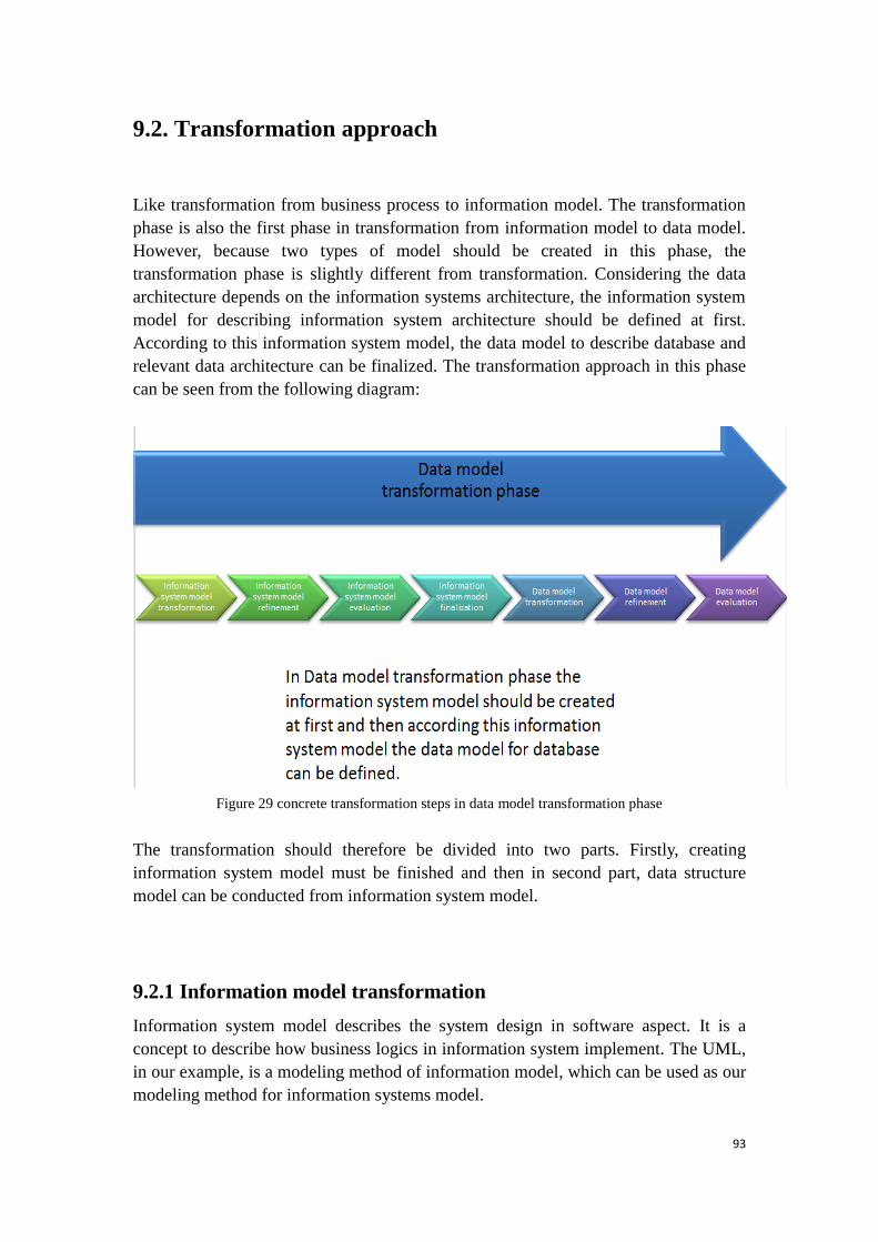
93
9.2. Transformation approach
Like transformation from business process to information model. The transformation
phase is also the first phase in transformation from information model to data model.
However, because two types of model should be created in this phase, the
transformation phase is slightly different from transformation. Considering the data
architecture depends on the information systems architecture, the information system
model for describing information system architecture should be defined at first.
According to this information system model, the data model to describe database and
relevant data architecture can be finalized. The transformation approach in this phase
can be seen from the following diagram:
Figure 29 concrete transformation steps in data model transformation phase
The transformation should therefore be divided into two parts. Firstly, creating
information system model must be finished and then in second part, data structure
model can be conducted from information system model.
9.2.1 Information model transformation
Information system model describes the system design in software aspect. It is a
concept to describe how business logics in information system implement. The UML,
in our example, is a modeling method of information model, which can be used as our
modeling method for information systems model.
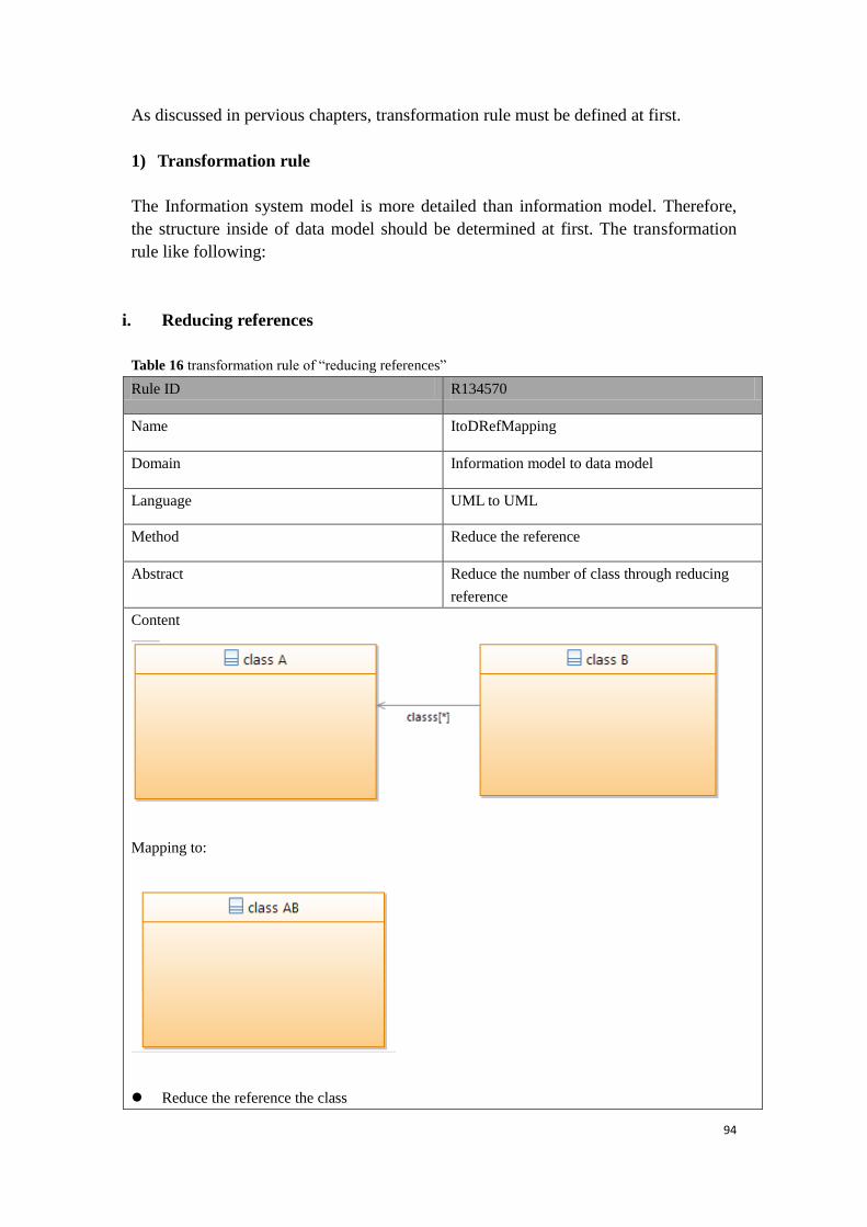
94
As discussed in pervious chapters, transformation rule must be defined at first.
1) Transformation rule
The Information system model is more detailed than information model. Therefore,
the structure inside of data model should be determined at first. The transformation
rule like following:
i. Reducing references
Table 16 transformation rule of “reducing references”
Rule ID R134570
Name ItoDRefMapping
Domain Information model to data model
Language UML to UML
Method Reduce the reference
Abstract Reduce the number of class through reducing
reference
Content
Mapping to:
Reduce the reference the class
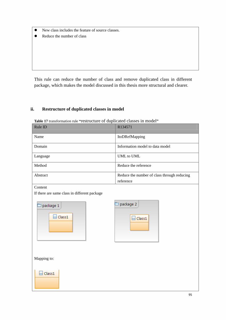
95
New class includes the feature of source classes.
Reduce the number of class
This rule can reduce the number of class and remove duplicated class in different
package, which makes the model discussed in this thesis more structural and clearer.
ii. Restructure of duplicated classes in model
Table 17 transformation rule “restructure of duplicated classes in model”
Rule ID R134571
Name ItoDRefMapping
Domain Information model to data model
Language UML to UML
Method Reduce the reference
Abstract Reduce the number of class through reducing
reference
Content
If there are same class in different package
Mapping to:
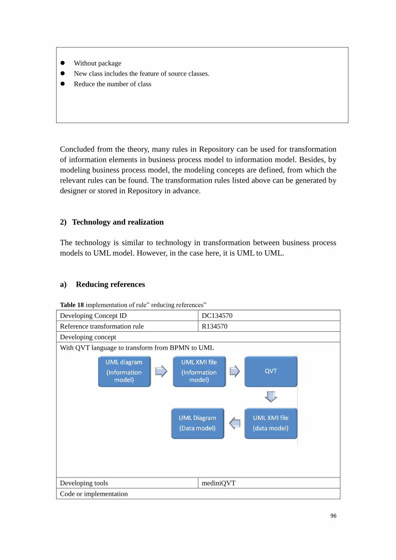
96
Without package
New class includes the feature of source classes.
Reduce the number of class
Concluded from the theory, many rules in Repository can be used for transformation
of information elements in business process model to information model. Besides, by
modeling business process model, the modeling concepts are defined, from which the
relevant rules can be found. The transformation rules listed above can be generated by
designer or stored in Repository in advance.
2) Technology and realization
The technology is similar to technology in transformation between business process
models to UML model. However, in the case here, it is UML to UML.
a) Reducing references
Table 18 implementation of rule” reducing references”
Developing Concept ID DC134570
Reference transformation rule R134570
Developing concept
With QVT language to transform from BPMN to UML
Developing tools mediniQVT
Code or implementation

97

98
b) Restructure of duplicated class in model
Table 19 implementation of rule” restructure of duplicated classes in model”
Developing Concept ID DC134571
Reference transformation rule R134571
Developing concept
With QVT language to transform from BPMN to UML
Developing tools mediniQVT
Code or implementation
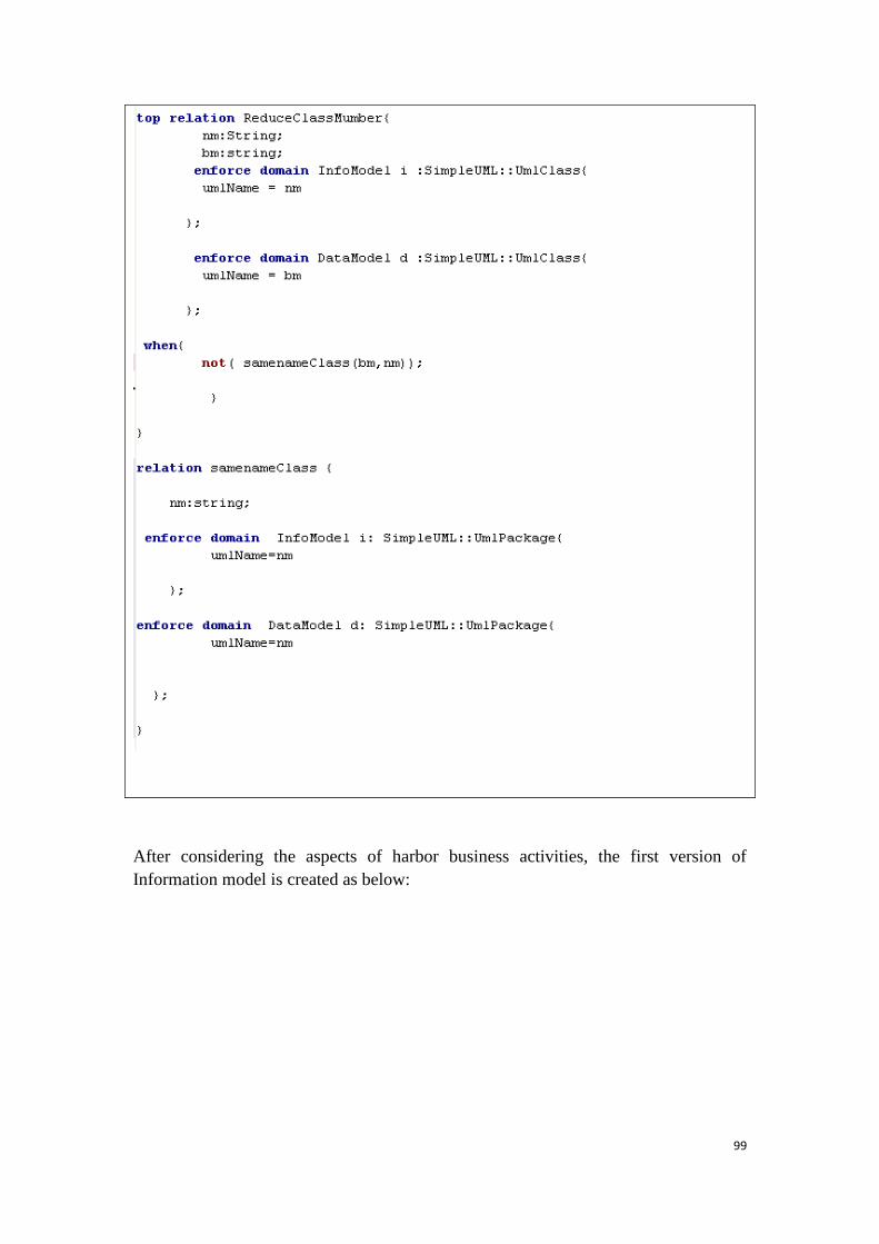
99
After considering the aspects of harbor business activities, the first version of
Information model is created as below:

100
1) Making work schedule
Figure 30 data model in aspect of “making work schedule”
After transforming, packages are eliminated in information system model. Seen from
the model above, general structure of information system for “Work schedule” can be
identified.

101
2) Marine transport and logistics
Figure 31 data model in aspect of “marine transport and logistics”

102
Additionally, similar to “work schedule”, the number of class of marine logistics is
reduced.
3) Land logistics
Figure 32 data model in aspect of “land logistics”
4) Warehouse task
Figure 33 data model in aspect of “warehouse task”

103
Seen from the diagram above, the redundant information classes are vanished.
However, the structure of model is not very good. So the logical structure and detail
information about each class must be defined in refinement phase.
9.2.2 Information model refinement
In this phase, the information models of different aspects will be summarized into one
structured model and detailed data will also be defined.
1) Structure of data model:
Figure 34 overview of improved data model
In this step, separated models are integrated into one universal model. This model
describes main components of information system and through which the structure of

104
information system can be identified. However, the above model still requires further
improvement, given some information is missed. Therefore, the following steps are
needed to complete the missing information.
2) Detail data for each information class
After defining the whole structure of information system model, details of data such
as attributes will be defined. The structure of information system model is more
detailed; developers can implement system according to this model. This model can
be also observed as a PIM model for MDA development to serve furthermore PSM
modeling and code realizing.
Seen from the following model, all information has been summarized in three types:
reports, documents and business information, according to concrete business activities,
relevant documents and reports will be created in system by referencing different
business information. These created documents and reports are also exchanged among
business partners and support whole harbor logistics process.
Still, this refinement phase should be companied by monitoring table to control and
record this complementation procedure. However, considering the emphasis of this
thesis, the concrete monitoring table will not be shown here.

105
Figure 35 finished information system model
.

106
9.2.3. Data structure model transformation
Data structure model is different from information system model; information system
model describes the business logics and the process of these business logics in
information system; while the emphasis of data structure model provides a concept or
method to describe how to save or store necessary information. From the software
engineering's point of view, information system model is like business logic server
while data structure model is more like database server behind of business logic server.
Therefore, data structure model must depend on information system model and should
be retrieved from information system model.
On other hand, data structure model is a concept of designing database or information
storage. Besides, the present popular database technologies are mostly based on
rational table and SQL language. Therefore, the transformation should focus on
transforming UML to rational table.
1) Transformation rule
As similar with pervious transformation, some transformation rules must be defined at
first to help transforming:
a) Table 20 class to table:
Rule ID R143568
Name ClassToTableMapping
Domain Information model to data model
Language UML to RDBMS
Method Mapping class to table
Abstract Convert class to table
Content
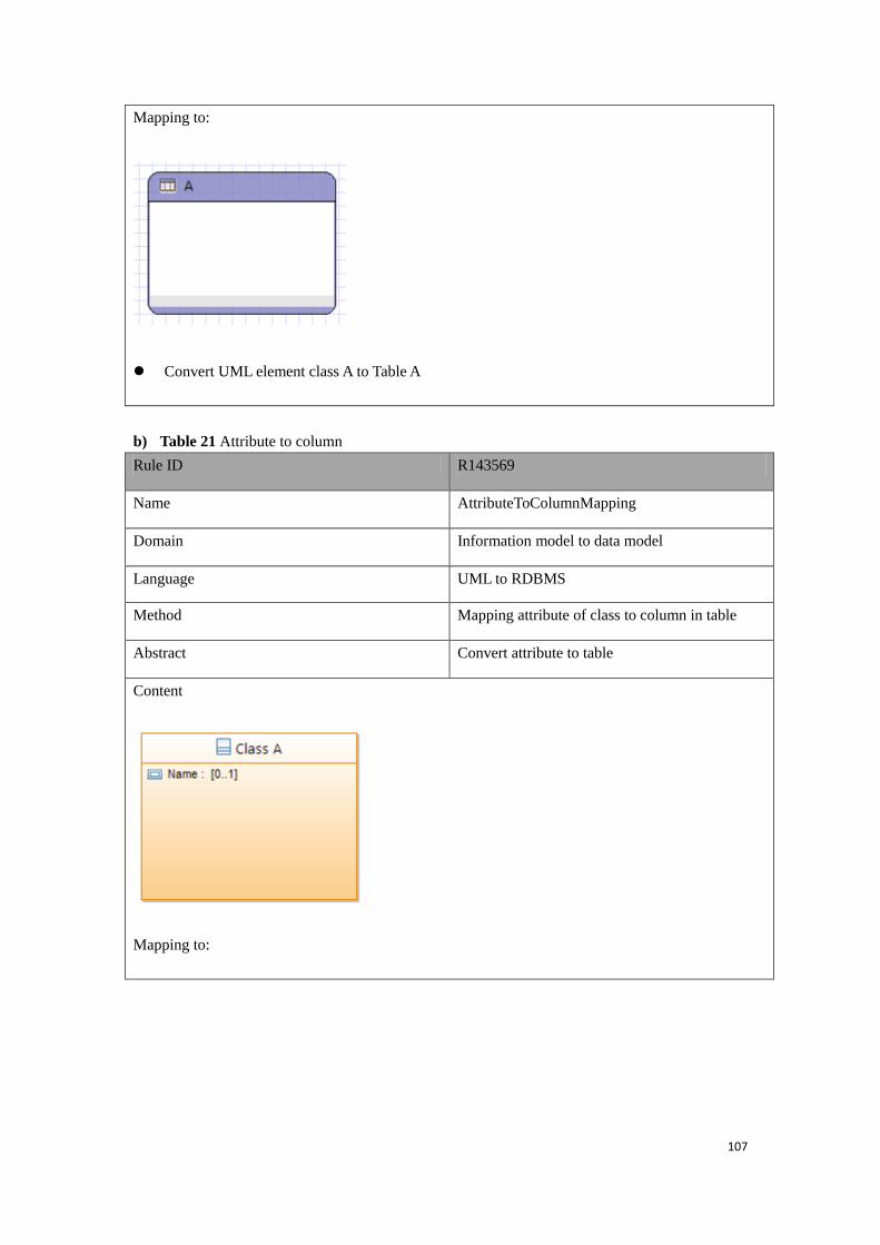
107
Mapping to:
Convert UML element class A to Table A
b) Table 21 Attribute to column
Rule ID R143569
Name AttributeToColumnMapping
Domain Information model to data model
Language UML to RDBMS
Method Mapping attribute of class to column in table
Abstract Convert attribute to table
Content
Mapping to:

108
Attributes of a class can be converted in a column of table.
Class should be mapped to table at first.
c) Table 22 map each association between persistent classes to a foreign key
Rule ID R143570
Name AssocToForeignKeyMapping
Domain Information model to data model
Language UML to RDBMS
Method Map each association between persistent classes
to a foreign key
Abstract Map each association between persistent classes
to a foreign key
Content
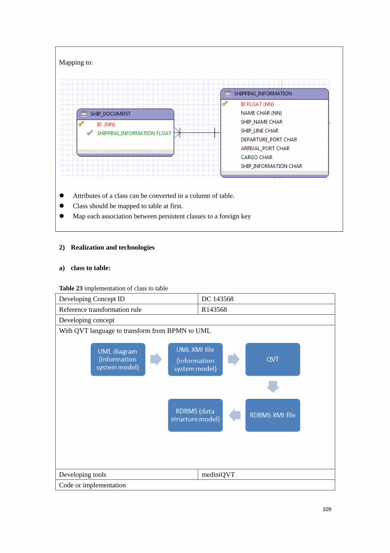
109
Mapping to:
Attributes of a class can be converted in a column of table.
Class should be mapped to table at first.
Map each association between persistent classes to a foreign key
2) Realization and technologies
a) class to table:
Table 23 implementation of class to table
Developing Concept ID DC 143568
Reference transformation rule R143568
Developing concept
With QVT language to transform from BPMN to UML
Developing tools mediniQVT
Code or implementation
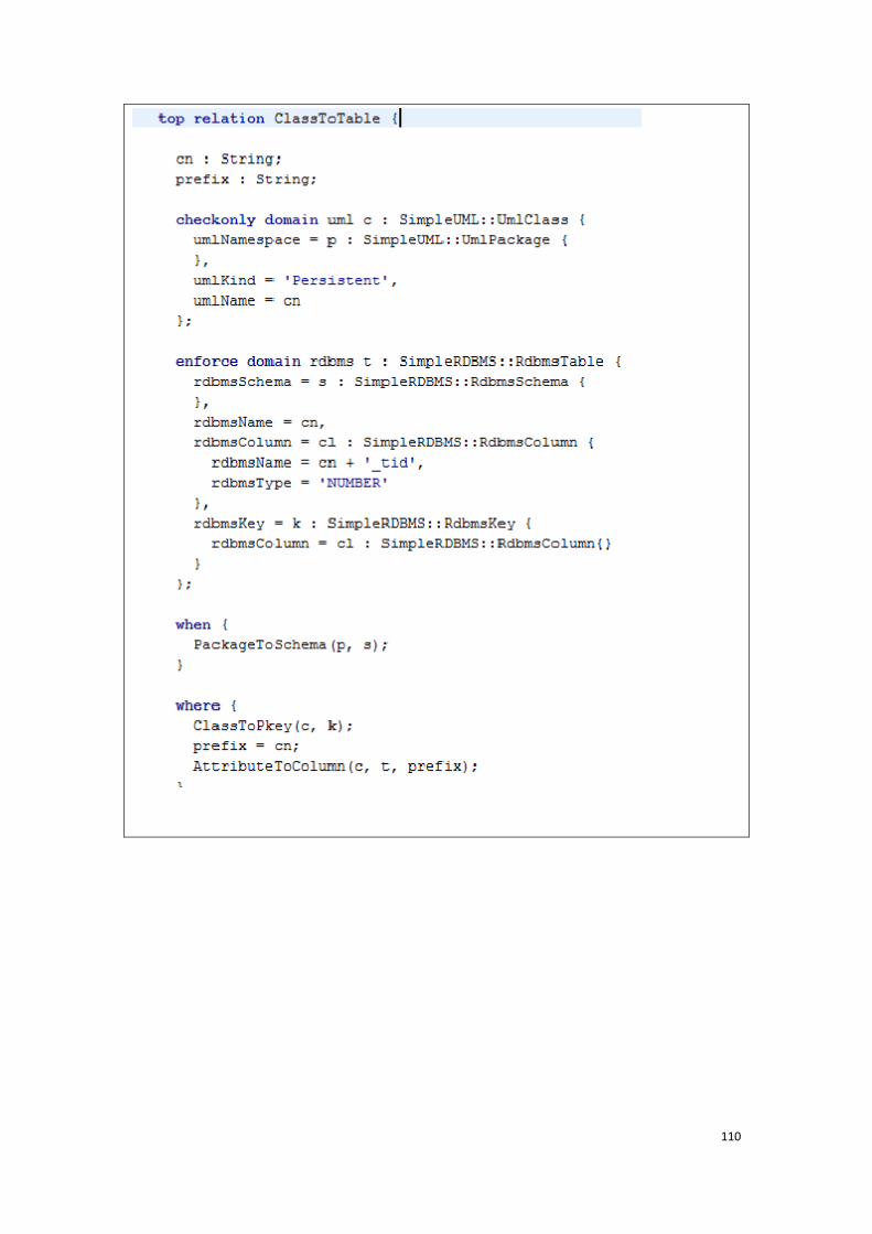
110
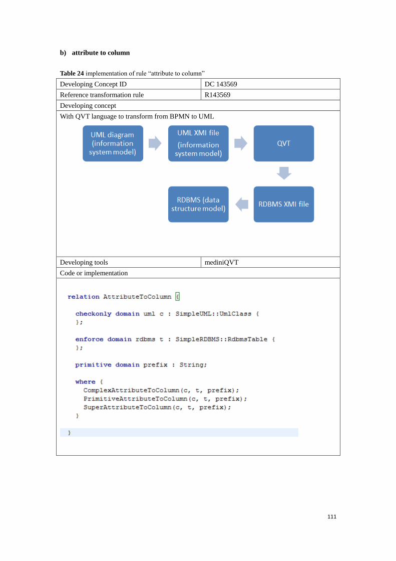
111
b) attribute to column
Table 24 implementation of rule “attribute to column”
Developing Concept ID DC 143569
Reference transformation rule R143569
Developing concept
With QVT language to transform from BPMN to UML
Developing tools mediniQVT
Code or implementation

112
c) Map each association between persistent classes to a foreign key
Table 25 implementation of “map each association between persistent classes to a foreign key”
Developing Concept ID DC 143570
Reference transformation rule R143570
Developing concept
With QVT language to transform from BPMN to UML
Developing tools mediniQVT
Code or implementation

113
After defining transformation rule and determining the implementation approach, the
transformation can be executed. The result is like following:
Figure 36 data structure model
This model looks like a class diagram, the meaning is nevertheless different. Each
rectangle means a table; in each table there are also many columns to describe
relevant attributes in class diagram. Relationships among tables are connected with
primary keys and foreign keys. However, this model is seen to be structural. For
example, in relation tables, there is no heritage relationship. Therefore, super classes
114
such as “report”, “document” and “business information” are transformed into tables,
which however, are not connected with other tables. On other hand, a lot of columns
repeat in different tables, which means data redundant and data superfluous. Therefore,
in the next refinement, the structure of data model must be redesigned according to
requirements of real business to make sure optimal storage of data.
9.2.4. Data structure model refinement
In this phase, the from information system model converted data structure model will
be refined further to reach an optimal solution for data storage.
According to the problems in above section mentioned, redundant attributes and
tables must be removed to ensure our model clear and structural.
1) Reducing number of tables and cleaning redundant attributes in the table.
The first step of refinement is to reduce unnecessary tables and relevant columns,
the purpose of this step is making model more structural and readable. That is also
a basis of further redesigning and optimizing data structure model.
Thus, like other refinement phase, this refinement must be recorded in monitor
table for evaluation and iterative development.

115
Figure 37 improved data structure model
The data structure model after first refinement step is shown in the above diagram.
Super classes such as “report”, “document” and “information” are removed from
this model. Relationship among reports, documents and saved business
information connected tighter than before. Primary keys for each table are
notified with red color and foreign keys are notified with green color.

116
9.3. Summary of this chapter
In this chapter , the order “transformation – refinement” is used to model the data
model.
Comparing with information model, the data model is more detailed and structured. In
our example, the UML and RDMS are used as the model languages. Interpreters or
developers can develop directly the database and server system with these two data
models. Thus, seen from information system model, the data are summarized into
three super classes which will be the basis for further design of infrastructure model.
On other side, these two models can be the final concept of our system in aspect of
software. They provide developers with general requirements and components of
system and database. They are also a basic logic idea for developing system. In
addition, IT manager can control and manage information system by using these two
models.
。

117
10. Infrastructure model
Infrastructure model is the last layer in our design process model and whole system
architecture. After defining system requirements from view of software, infrastructure
model is a model to describe the platform which applications or systems can run on it.
For different stakeholders in developing, infrastructures have different meanings. For
example, for developers, infrastructure is the platform to run their applications on. For
network managers, infrastructure is collections of all network equipment. For system
administrators, infrastructure is all equipment he manages, and for IT architects it is
the basic layer to build business services on.21
Different meaning of the infrastructure therefore causes different models. From only
the data model, it is not an easy task to get the whole infrastructure model for all
aspects of system. Therefore, the transformation from data model to final
infrastructure model becomes difficult.
However, from the definition about the transformation in process model, the
infrastructure model from software component view can be defined. Firstly, the data
model can be transformed to get the infrastructure model in software component view,
after which the infrastructure in other aspects can be completed according the
software component view in the refinements phase.
On other hand, infrastructure model is based on above models. Requirements
analyzing can be helpful to finalize the whole system infrastructure. Therefore, after
1:1 transformation and mapping in transformation phase a requirement analyzing
method in refinement phase can be used to define our infrastructure model.
21
IT Infrasturcture model, by Over Sjaak Laan
http://www.sjaaklaan.com/archives/archive_2006-m08.php
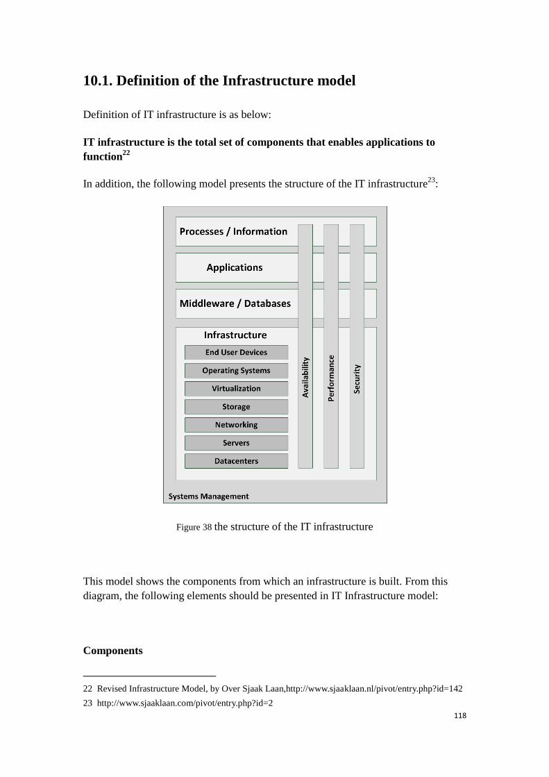
118
10.1. Definition of the Infrastructure model
Definition of IT infrastructure is as below:
IT infrastructure is the total set of components that enables applications to
function22
In addition, the following model presents the structure of the IT infrastructure23
:
Figure 38 the structure of the IT infrastructure
This model shows the components from which an infrastructure is built. From this
diagram, the following elements should be presented in IT Infrastructure model:
Components
22 Revised Infrastructure Model, by Over Sjaak Laan,http://www.sjaaklaan.nl/pivot/entry.php?id=142
23 http://www.sjaaklaan.com/pivot/entry.php?id=2
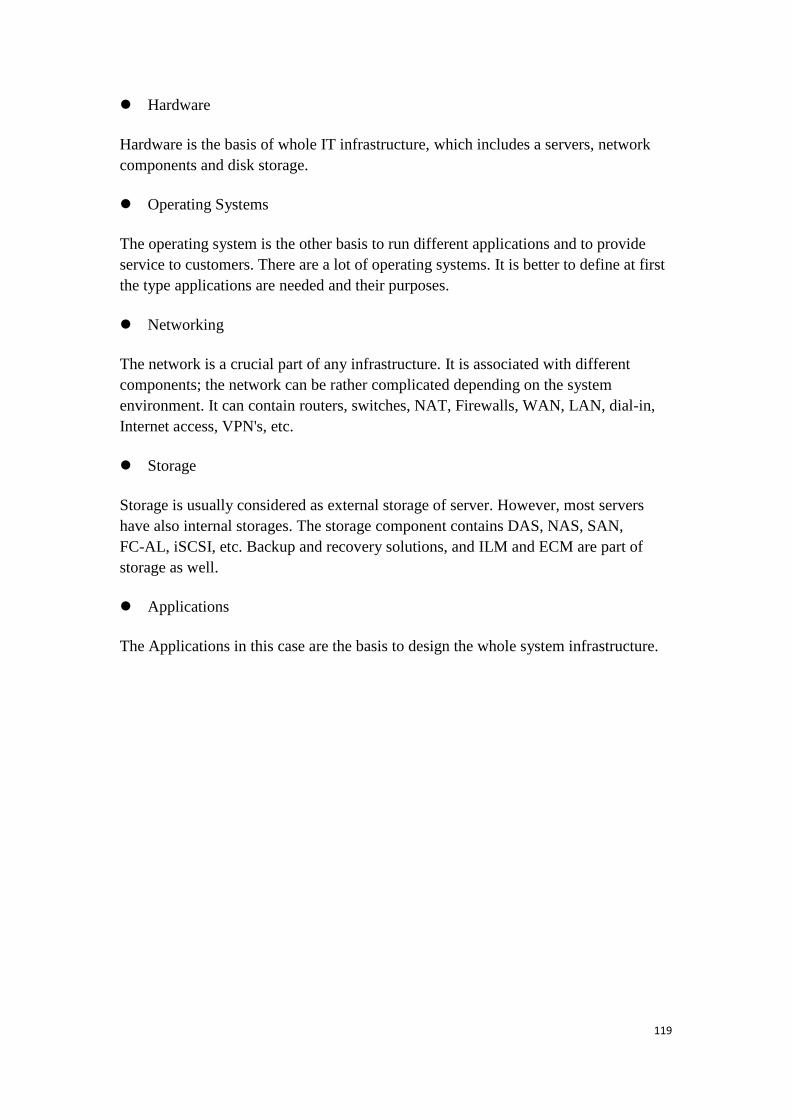
119
Hardware
Hardware is the basis of whole IT infrastructure, which includes a servers, network
components and disk storage.
Operating Systems
The operating system is the other basis to run different applications and to provide
service to customers. There are a lot of operating systems. It is better to define at first
the type applications are needed and their purposes.
Networking
The network is a crucial part of any infrastructure. It is associated with different
components; the network can be rather complicated depending on the system
environment. It can contain routers, switches, NAT, Firewalls, WAN, LAN, dial-in,
Internet access, VPN's, etc.
Storage
Storage is usually considered as external storage of server. However, most servers
have also internal storages. The storage component contains DAS, NAS, SAN,
FC-AL, iSCSI, etc. Backup and recovery solutions, and ILM and ECM are part of
storage as well.
Applications
The Applications in this case are the basis to design the whole system infrastructure.

120
10.2. Transformation
As discussed in the above section, infrastructure means so many things in system
developments. Therefore, to determinate a completed infrastructure by only using
transformation rules from data model is not possible. According features of data
model, the corresponding application components have to be identified first before
conducting and finishing the whole infrastructure model in the refinement phase.
Therefore, like transformations in previous chapters, the transformation phase is also
the first phase in transformation from data model to infrastructure model.
1) Transformation rule
Table 26 transformation rule “define the application component”
Rule ID R134580
Name DtoInfraCompentMapping
Domain data model to infrastructure model
Language UML to UML
Method Define the application component
Abstract Reduce the number of class through reducing
reference
Content
Mapping to:
Covert super class into component
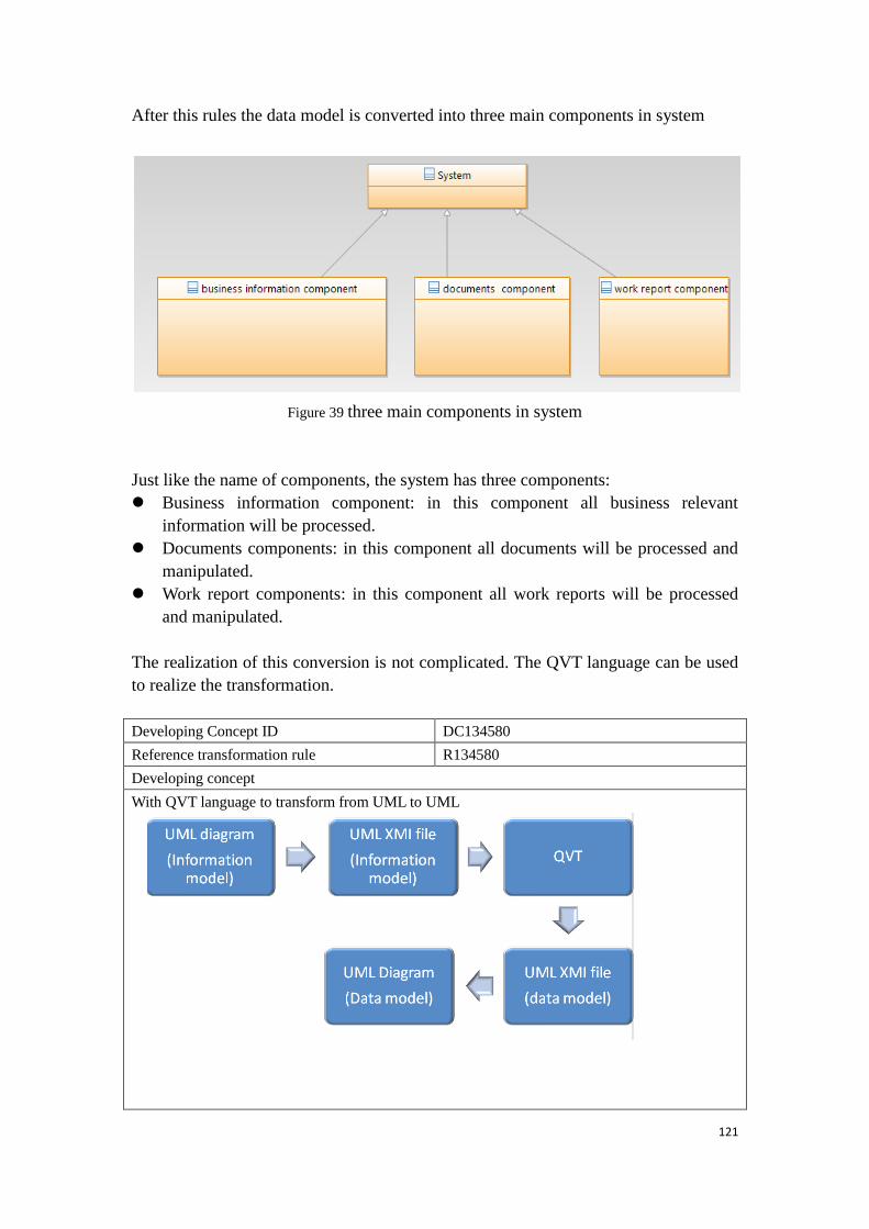
121
After this rules the data model is converted into three main components in system
Figure 39 three main components in system
Just like the name of components, the system has three components:
Business information component: in this component all business relevant
information will be processed.
Documents components: in this component all documents will be processed and
manipulated.
Work report components: in this component all work reports will be processed
and manipulated.
The realization of this conversion is not complicated. The QVT language can be used
to realize the transformation.
Developing Concept ID DC134580
Reference transformation rule R134580
Developing concept
With QVT language to transform from UML to UML

122
Developing tools mediniQVT
Code or implementation
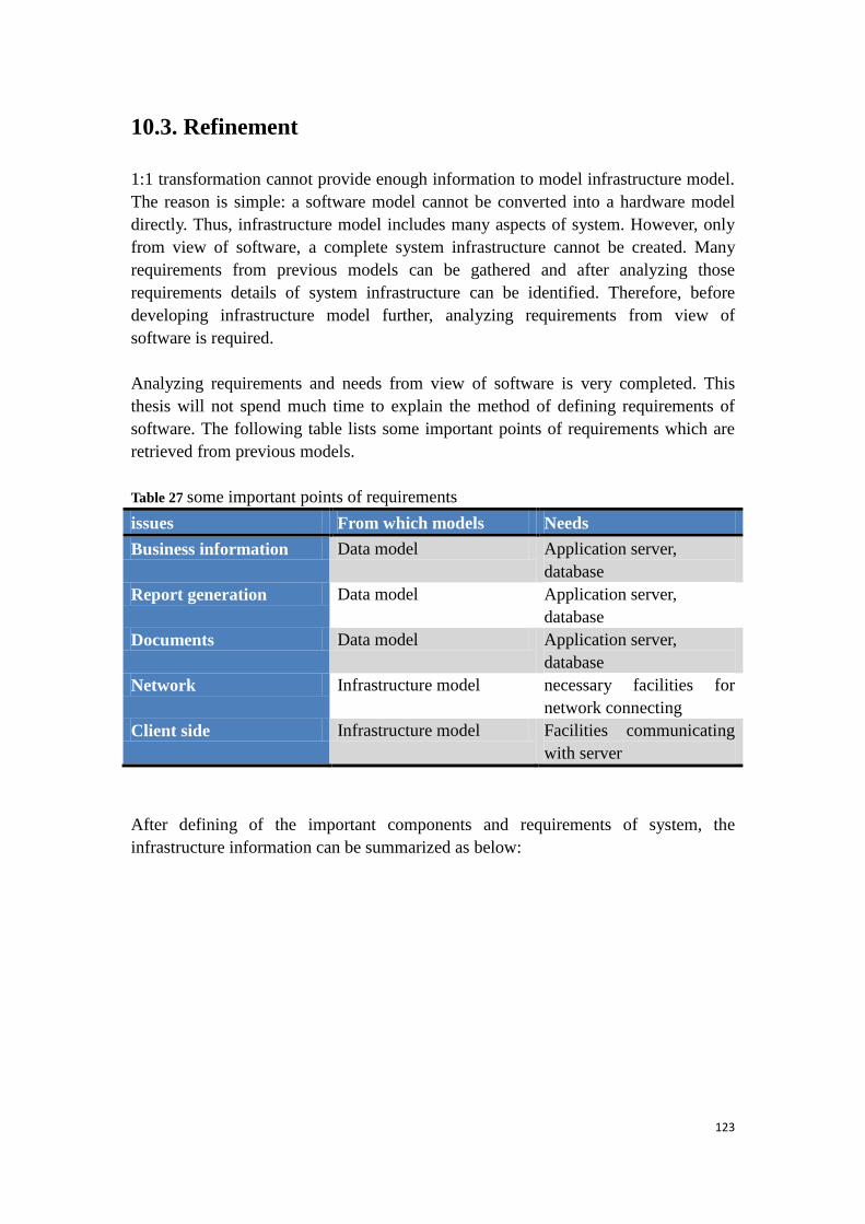
123
10.3. Refinement
1:1 transformation cannot provide enough information to model infrastructure model.
The reason is simple: a software model cannot be converted into a hardware model
directly. Thus, infrastructure model includes many aspects of system. However, only
from view of software, a complete system infrastructure cannot be created. Many
requirements from previous models can be gathered and after analyzing those
requirements details of system infrastructure can be identified. Therefore, before
developing infrastructure model further, analyzing requirements from view of
software is required.
Analyzing requirements and needs from view of software is very completed. This
thesis will not spend much time to explain the method of defining requirements of
software. The following table lists some important points of requirements which are
retrieved from previous models.
Table 27 some important points of requirements
issues From which models Needs
Business information Data model Application server,
database
Report generation Data model Application server,
database
Documents Data model Application server,
database
Network Infrastructure model necessary facilities for
network connecting
Client side Infrastructure model Facilities communicating
with server
After defining of the important components and requirements of system, the
infrastructure information can be summarized as below:

124
Table 28 infrastructure model in aspect of hardware
Hardware
The hardware infrastructure is like following:
Operating Systems
Client: windows7 or XP
Server: Windows Server,
Oracle server: Oracle Solaris
Networking
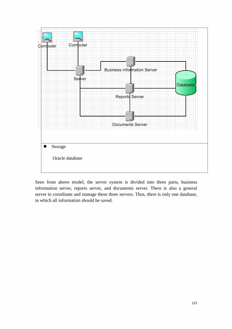
125
Storage
Oracle database
Seen from above model, the server system is divided into three parts, business
information server, reports server, and documents server. There is also a general
server to coordinate and manage these three servers. Thus, there is only one database,
in which all information should be saved.

126
10.4. Summary of this chapter
Infrastructure model is last layer of the design process model. It bases on other
models in design process model and describes relevant system and hardware
information. Therefore, the infrastructure model is extended from other models in
design process model. However, its features decide that it cannot be transformed from
other model directly.
The approach to transform this model is therefore like this: in transformation phase
the from 1:1 transformation, requirements for building system infrastructure can be
acquired, by analyzing which infrastructure model can be modeled and refined in
refinement phase.
The 1:1 transformation in this part does not play a main role. However, by following
steps and methods of design process model, needed model can be analyzed and
modeled. The idea of logical transformation is also throughout in this part.
127
11. Conclusion and outlook
Design and development of IT system is an eternal research subject in field of
computer science. And how to develop IT systems efficiently and optimally is
emphasis of this research. Comparing with other software development frameworks
and methodologies, the design process model focuses on design phase of system
development and presents design concepts and logics by using different types of
models. Thus, M2M transformations between 2 different models in design process
model ensure the coherence and logic of design. The final concept which consists of
different models is also an overview of system and provides a planning or controlling
method for system management.
The biggest feature of this design process model is making the design phase standard
and logic, furthermore, the design phase become more transparent through recording
transformation rules and transformation steps. It can reduce probabilities of
information lost and data redundancy.
On other side, this design process model organizes different system models. It is an
overview of whole information system. That is more like blueprint in construction. It
improves the level of transparence among different development teams and phases. It
is very helpful for further integration and updating. IT managers can also understand
the situation of systems through this design process model and make IT strategy for
the enterprise more easily and optimally.
Therefore, the design process model not only can be used alone in system design, in
additional, it can be used as a method to combine with other software methodologies
for developing, updating and managing information system.
Throughout this thesis, the main technology and concept for modeling and
transformation is from MDA. It inherits some features of MDA such as with code to
achieve the Model to Model transformation, and also, it gives the designer own
autonomy to perfect different system models. So this design process model can also as
a complementation in transformation between CIM and PIM. The results of each step
in design process model can be looked upon as Inputs of PIM.

128
Figure 40 the relationship between MDA development and design process model
However, this design process model is now in his Infancy, there are a lot of
improvements we need to do in future. It includes mainly in 4 aspects:
1) Determining Sub steps for each modeling
The design process model has already defined 4 phases to achieve final system
concept. But there are not any organization structures or methods for each phase.
That let creating and updating models inside of same phase become non
-standardized. The next steps of research should detail this 3 phases and make a
standardized modeling approach for each model.
2) Complementing the repository
Transformations rules and methods in repository should be updated and
complemented. The repository should include transformation technologies as
more as possible. How to summarize and manage those transformation approaches
should be defined in further work.
3) Interface for other different models.
The design process model defined 4 types of models. But developers usually need
some other models to describe special requirements. Therefore, the design process
model needs reference or integration rules. So that users of design process model
can understand and utilize other models as easy as possible.

129
12. Literature
1. Barbara C. Mcnurlin, Ralph h.Sprague, JR.: Information systems management in
practice 5 edition, Upper Saddle River, NJ 07458
2. Klaus Zeppenfeld / Regine Wolters: Generative Software-Entwicklung mit der
MDA, Spektrum Akademischer Verlag,
3. Univ.Prof.Dr. Dimitris Karagiannis, Mag. Sandra Hintringer, Mag. Srdjan
Zivkovic(8.2009): Integration: Hybrid Modeling, Springer-Verlag, heft 7-8.2009
4. Uni-Prof. Dr. Dimitris Karagianis, Haradkühl, Franz Bayer, Stefan Junginger:
Enterprise model Integration, September 2003, LNCS 2738, pp. 379-392
5. Kap Hwan Kim, Bong Hee Hong: Maritime Logistics and Applications of
Information Technologies, ISBN 10.1109/ICCIE.2010.566841
6. Sergey Smirnov, Hajo A. Reijers, Thijs Nugteren, Mathias Weske: Business
Process Model Abstraction: Theory and Practice,
http://www.hpi.uni-potsdam.de/fileadmin/hpi/source/Technische_Berichte/HPI_35
_Business_Process_Model_Abstraction_-_Theory_and_Practice.pdf
7. Naritoshi Tsugane, Takeo Asakura: Use of Business Modeling in Requirements
Definition Phase, http://www.fujitsu.com/downloads/MAG/vol42-3/paper04.pdf
8. Martin Owen and Jog Raj: BPMN and Business Process Management
Introduction to the New Business Process Modeling Standard,
http://www.omg.org/bpmn/Documents/6AD5D16960.BPMN_and_BPM.pdf
9. John D. Poole(4.2010): Model-Driven Architecture: Vision, Standards And
Emerging Technologies,
http://www.omg.org/mda/mda_files/Model-Driven_Architecture.pdf
10. lian-she LI, Xiao-li MIAO: Research on Mode Selection for Developing Port
Logistics in China Based on Analytical Hierarchy Process -Taking Tianjin Port
Logistics as an Example, 978-1-4244-6484-5110 ©2010 IEEE
11. Höfferer, Peter(2010): Achieving business process model interoperability using
metamodels and ontologies,
http://www.dke.at/fileadmin/DKEHP/publikationen/metamodell/Hoefferer_BP_int
eroperability_ontologies.pdf
12. FU Xi-xu, GONG Xi-zhang, ZHANG Shu, PAN Dong-ming (9.2010): Research
and Discussion on Logistics Information Architecture of Lingang Region.
130
IN: Logistics Sic-Tech, No.9, 2010
13. Pau Ginner, Victoria Torres, Vicente Pelechano: Bridging the Gap between BPMN
and WS-BPEL. M2M Transformations in Practice,
http://ceur-ws.org/Vol-261/paper06.pdf
14. Laszlo Legyel: An Overview of QVT, www.vmts.aut.bme.hu
15. SHU Fan, XU Ziqi, HUANG Youfang, MI weijian: A GIS-based information
sharing infrastructure for container port logistics using data mining and visual
technology,
http://dx.doi.org/10.1049/cp:20061070
16. Ondrej Macek, Karel Richta: The BPM to UML activity diagram transformation
using XSLT,
http://www.ksi.mff.cuni.cz/~richta/publications/Dateso2009_Macek_Richta.pdf
17. Juan de Lara, Esther Guerra: Pattern-based Model-to-Model Transformation,
http://astreo.ii.uam.es/~jlara/papers/ICGT_08.pdf
18. Cao pengfei, Yang Shaoxiong, Ye Chuanbiao: The Research Based on MDA and
Search Egnine Technology for the automation platform of Software,
http://wenku.baidu.com/view/44622205eff9aef8941e065d.html
19. Over Sjaak Laan: Revised Infrastructure Model,
http://www.sjaaklaan.nl/pivot/entry.php?id=142
20. A. Pras,J. Schoenwaelder: On the Difference between Information Models and
Data Models, by A. Pras,J. Schoenwaelder, http://www.ietf.org/rfc/rfc3444.txt

131
LEBENSLAUF
Bakk. B.A. Zhan CHEN
PERSÖNLICHE INFORMATION
Geburtsdatum: 13.09.1981 in Peking
Staatsangehörigkeit: China
Familienstand: Ledig
AUSBILDUNG
Seit 10.2009 Wirtschaftsinformatik Master Studium an der Uni. Wien
10.2005- 09.2009 Wirtschaftsinformatik Bachelor Studium an der Uni.Wien
09.2000- 07.2004 Automatisierung Bachelor Studium in Peking, China
ZUSATZQUALIFIKATIONEN
1. gute Kenntnisse und Erfahrung von EDV Software und Hardware
2. gute Erfahrung von SAP,SQL und Adobe Design Software
3. gute Erfahrung von Software -Web Engineering und Entwicklung
4. gute Erfahrung von Business Prozesse Modellierung
5. gute Erfahrung und Kenntnisse von elektronische Automatisierung
6. gute Programmierungsfähigkeit: Java, C++,C#,PHP,JSP,J2EE, XML,
Javascript, CSS.HTML usw..