Embed Size (px)
Citation preview

A Probabilistic-Mechanistic Approach to Modeling
Stress Corrosion Cracking in Alloy 600 Components
with Applications
Gary Wu
University of Maryland
College Park
PSAM 2011/ESREL 2012
June 25 – 29, 2012
Helsinki, Finland
Copyright 2012 by M. Modarres
Mohammad Modarres
University of Maryland
College Park

Overview
Introduction
Stress Corrosion Cracking (SCC) Background
Model Development Process
Crack Propagation Simulation Process
Conclusion
2
Introduction
3
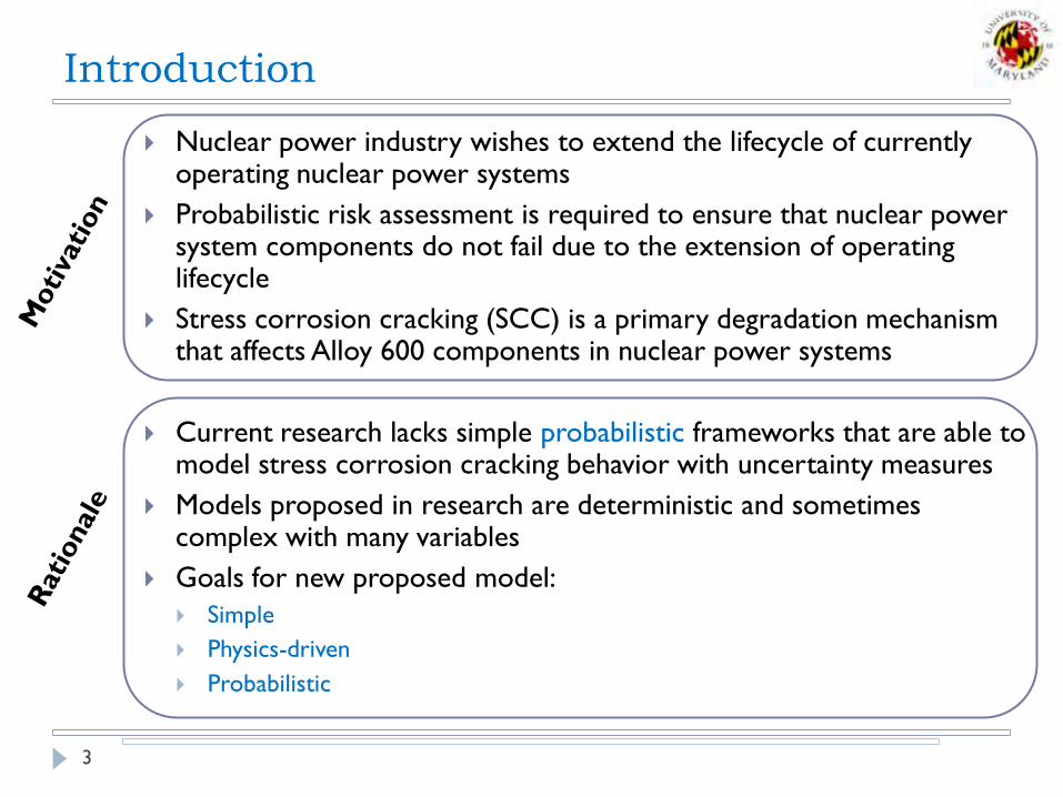
Nuclear power industry wishes to extend the lifecycle of currently operating nuclear power systems
Probabilistic risk assessment is required to ensure that nuclear power system components do not fail due to the extension of operating lifecycle
Stress corrosion cracking (SCC) is a primary degradation mechanism that affects Alloy 600 components in nuclear power systems
Current research lacks simple probabilistic frameworks that are able to model stress corrosion cracking behavior with uncertainty measures
Models proposed in research are deterministic and sometimes complex with many variables
Goals for new proposed model:
Simple
Physics-driven
Probabilistic

Introduction: Project Approach
4
Literature review to understand the proposed mechanisms
and models that characterize stress corrosion cracking (SCC)
General SCC of Alloy 600
Specific SCC of Steam Generator Tubes
Develop a simple, physics-driven model to estimate the
crack growth rate of stress corrosion cracking of Alloy 600
with uncertainty measures
Develop a simulation process to propagate stress corrosion
cracking using developed probabilistic model

Stress Corrosion Cracking
5
[1]
Stress corrosion cracking can be defined as a delayed cracking
mechanism which only occurs with the combination of:
Susceptible Material, Corrosive Environment, Constant Tensile
Stress
Can often cause catastrophic failure with little to no warning [2]
[3]

Adapting Existing Model
6
MRP model developed by Hicking et al. from the Electric Power Research
Institute [4] for PWSCC
SCC factors considered:
Temperature (Arrhenius relationship)
Constant Tensile Stress (Power-Law
relationship)
aYKapplied
σapplied – total effective stress
a – crack depth or length
Y – shape parameter

Incorporation of Other SCC Factors
7
pH is a property of the corrosive environment and has been shown to have an effect on SCC propagation rates [5] such that an increase of pH value increases the SCC propagation rate
Power-Law relationship is
proposed for crack propagation
rate dependence on pH
pH Yield Strength is a property of the
susceptible material and has also been shown to have an effect on SCC propagation rates [6], such that an increase in yield strength increases the crack propagation rate
Power-Law relationship is also proposed for crack propagation rate dependence on yield strength
Yield Stress

Final Proposed Model
8
PWSCC Propagation Model for Alloy 600 Components
[6]
[9]

Final Proposed Model
9

Bayesian Regression Analysis
10
Estimate the model parameters using SCC propagation data
The posterior distribution for the model parameters is:

Bayesian Regression Analysis
11
Stage I Model Parameter Marginal Distributions
Stage II Model Parameter Marginal Distributions

Simulation Assumptions
12
Simulation Conditions
Alloy 600 Material
High Temperature Primary Water
MATLAB code to model Steam Generator (SG) Tubes
Does not simulate regular inspection and maintenance
“Steam Generator Tube Rupture” versus “Failure”
“Steam Generator Tube Rupture” (SGTR) occurs when a crack
substantially contributes to primary-to-secondary side leak rates
exceeding certain amounts (100 gallons per minute) [7]
“Failure” in this simulation is defined as a 100% through-wall extent
across the thickness of the steam generator tubes.
Process Summary
13
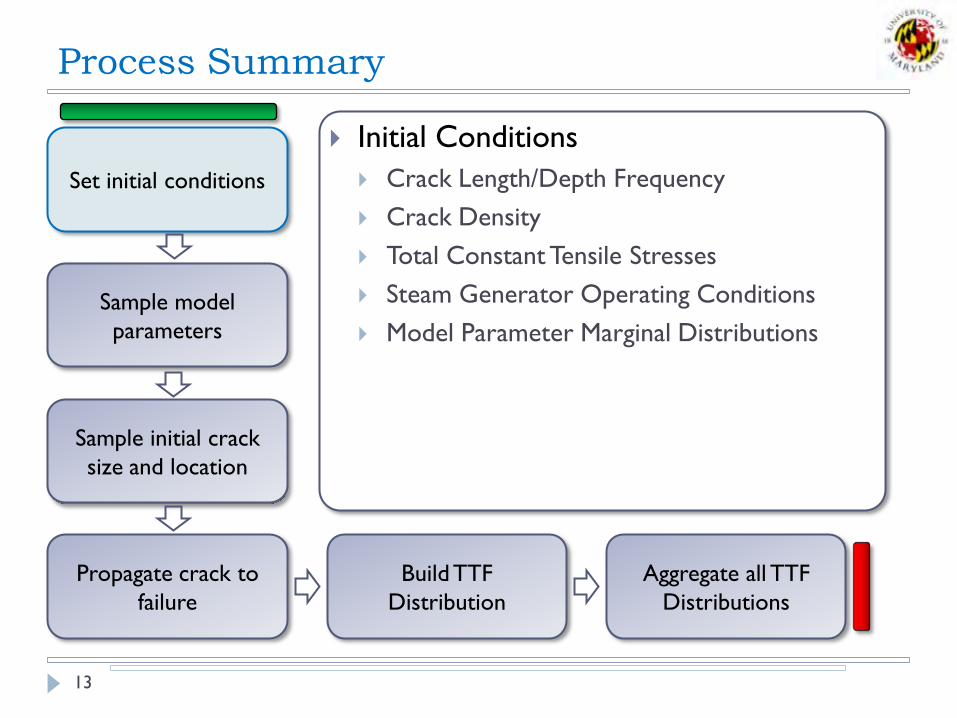
Set initial conditions
Sample model
parameters
Sample initial crack
size and location
Propagate crack to
failure
Build TTF
Distribution
Aggregate all TTF
Distributions
Initial Conditions
Crack Length/Depth Frequency
Crack Density
Total Constant Tensile Stresses
Steam Generator Operating Conditions
Model Parameter Marginal Distributions

Process Summary
14
Set initial conditions
Sample model
parameters
Sample initial crack
size and location
Propagate crack to
failure
Build TTF
Distribution
Aggregate all TTF
Distributions
Sample model parameters to formulate
a deterministic model for crack
propagation rate
Stage I
{C, n, m}
Stage II
{C, n, m, β}

Process Summary
15
Set initial conditions
Sample model
parameters
Sample initial crack
size and location
Propagate crack to
failure
Build TTF
Distribution
Aggregate all TTF
Distributions
Sample initial crack distribution for
crack size and randomly choose a
location for PWSCC
U-bend Region
Tube support plate interactions
Expansion Transition Region
Different total stresses at three
locations due to varying amounts of
residual stress

Process Summary
16
Set initial conditions
Sample model
parameters
Sample initial crack
size and location
Propagate crack to
failure
Build TTF
Distribution
Aggregate all TTF
Distributions

Process Summary
17
Set initial conditions
Sample model
parameters
Sample initial crack
size and location
Propagate crack to
failure
Build TTF
Distribution
Aggregate all TTF
Distributions

Process Summary
18
Set initial conditions
Sample model
parameters
Sample initial crack
size and location
Propagate crack to
failure
Build TTF
Distribution
Aggregate all TTF
Distributions

Process Summary
19
Set initial conditions
Sample model
parameters
Sample initial crack
size and location
Propagate crack to
failure
Build TTF
Distribution
Aggregate all TTF
Distributions

Discussion
20
Results are dependent on
simulation assumptions and
initial distributions
Initial crack size distribution
from inspection data at 11 years
of operation
Not all cracks are in the crack
propagation stage
Assume denting at tube support
plates
Assume residual stresses are the
same for all cracks in each
location

Discussion
21
Before being able to estimate SGTR frequency using this
model and simulation
Crack behavior after 100% through-wall extent
Implement a leak rate model for defined crack sizes
Consider regular inspection intervals and maintenance of SG tubes
Plugging
Sleeving
Process for SGTR Frequency
Determine leak rates for final crack sizes
Check for sudden increase of leak rate exceeding 100 gallons per minute
SGTR Frequency = 1 / Time of leak rate exceeding specified limits

Discussion
22
Suppose more than one crack with a constant leak rate within
an hour time period is required to exceed the specified limit
Simulation provides ability to estimate the time required to reach
specific limit (e.g. can be applied to estimate SGTR frequency)
2 Cracks
3 Cracks
4 Cracks

Conclusion
23
Explored the stress corrosion cracking mechanism in general
and specifically for Alloy 600 steam generator (SG) tubes
Proposed an simple, probabilistic model based on physics-
driven relationships explicitly incorporating factors of SCC:
Stress
Temperature
pH
Yield Strength
Developed a crack propagation simulation process for Alloy
600 SG Tubes in Primary Water conditions that predicts the
time-to-100% through-wall extent with uncertainty measures

Questions?
24
References
25
[1] Denny A Jones, Principles and Prevention of Corrosion, 2nd ed. Upper Saddle River, United States of America: Prentice-Hall, Inc., 1996.
[2] Joseph R Davis, Ed., Corrosion - Understanding The Basics. Materials Park, United States of America: ASM International, 2000.
[3] Son Le Hong, Claude Amzallag, and Angel Gelpi, "Modelling of Stress Corrosion Crack Initiation on Alloy 600 in Primary Water of PWRs," in International Symposium of Environmental Degradation of Materials in Nuclear Power Systems - Water Reactors, Newport Beach, 1999, pp. 115-122.
[4] Hicking, A McIlree, and R Pathania, "Crack Growth Rates for Evaluating Primary Water Stress Corrosion Cracking (PWSCC) of Thick-Wall Alloy 600 Material (MRP-55)," Electric Power Research Institute, Palo Alto, NRC ADAMS Accession No. ML023010510, 2002.
[5] R B Rebak, A R McIlree, and Z Szklarska-Smialowska, "Effects of pH and Stress Intensity on Crack Growth Rate in Alloy 600 in Lithated + Borated Water at High Temperatures," in International Symposium on Environmental Degradation of Materials in Nuclear Power Systems - Water Reactors, Monterey, 1991, pp. 511-524.
[6] R B Rebak, Z Xia, and Z Szklarska-Smialowska, "Effect of Temperature and Cold Work on the Crack Growth Rate of Alloy 600 in Primary Water," Corrosion, vol. 51, no. 9, pp. 689-697, 1995.
[7] R Tregoning, L Abramson, and P Scott, "Estimating Loss-of-Coolant Accident (LOCA) Frequencies Through the Elicitation Process, U.S. Nuclear Regulatory Commission, Washington DC, NUREG/CR NUREG-1829, 2008

Backup Slides
26

Factors of Stress Corrosion Cracking
27
Alloys Environments
Stainless
Steels
- Chlorides
- Caustic
- Water + O2
Nickel
Alloys
- Hot caustic
- High temperature water
- Steam
Cooper
Alloys
- Ammonia
- Water vapor + SO2
Aluminum
Alloys
- Water vapor
- N2O4
- Alcohols
Titanium
Alloys
- Methanol
- Dilute HCl or H2SO4
[1]
[2]

Factors of Stress Corrosion Cracking
28
[1]
Tensile stress required for SCC
is of constant magnitude,
usually less than macroscopic
yield strength
Total constant stress is the
arithmetic sum of:
Externally applied stress as a result
of operating conditions
Residual stresses as a result of
material manufacturing processes

Steam Generator Tube Background
29
104 nuclear reactors in the United States
35 are Boiling Water Reactors
69 are Primary Water Reactors
Primary Water Reactors
Two closed-loop systems
Primary loop uses primary coolant (high temperature water) to circulate
heat energy from the radioactive material
Secondary loop uses treated feedwater to turn into steam for power
generation
Steam generator acts as the connection between primary and secondary
loops

Steam Generator Tube Background
30
[3] [4]
Primary Water Reactor

Steam Generator Tube Background
31
[3] [4]
Recirculating Steam Generator
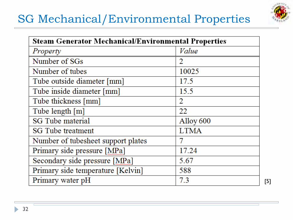
SG Mechanical/Environmental Properties
32
[5]

PWSCC Region Assumptions
33
1 Yield strength is calculated assuming the 2% CW at expansion transition, 7% CW at TSP with a dent, 9% at U-bend 3 U-bend flaw density is estimated given flaw densities for expansion transition and TSP
[3]
[6]
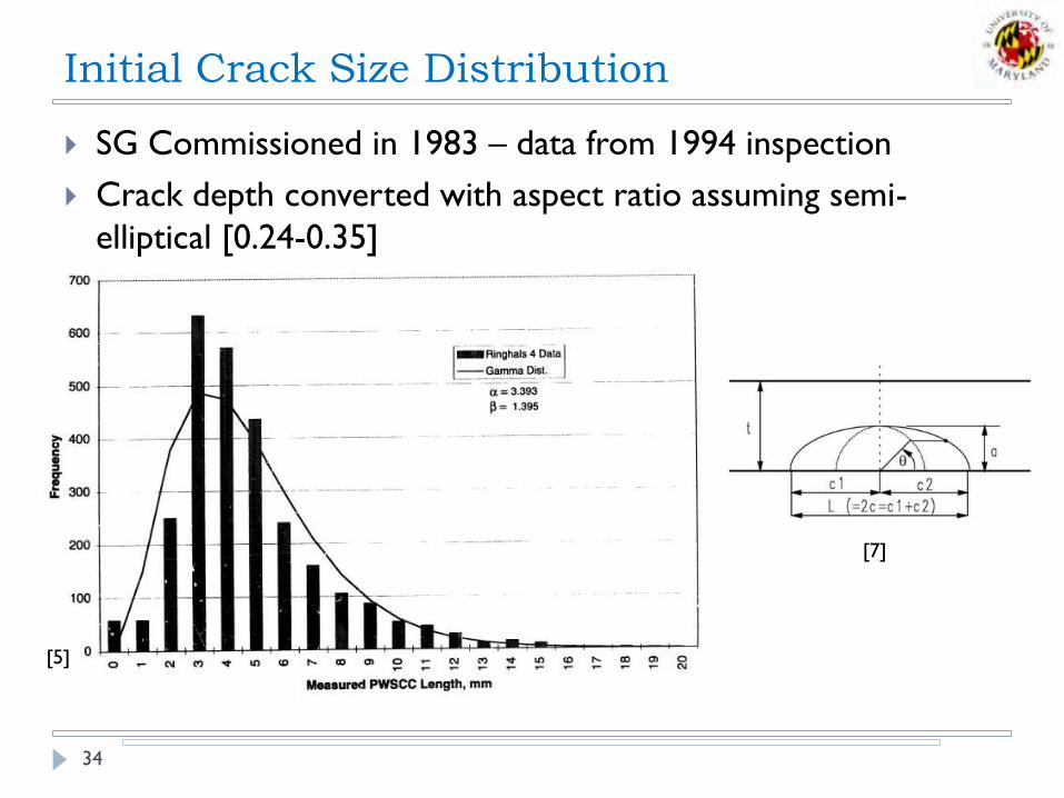
Initial Crack Size Distribution
34
SG Commissioned in 1983 – data from 1994 inspection
Crack depth converted with aspect ratio assuming semi-
elliptical [0.24-0.35]
[5]
[7]
References
35
[1] Denny A Jones, Principles and Prevention of Corrosion, 2nd ed. Upper Saddle River, United States
of America: Prentice-Hall, Inc., 1996.
[2] R B Rebak and Z Szklarska-Smialowska, "The Mechanism of Stress Corrosion Cracking of
Alloy 600 in High Temperature Water," Corrosion Science, vol. 38, no. 6, pp. 971-988, 1996.
[3] Peter N Paine, "Steam Generator Reference Book, Revision 1," Electric Power Research
Institute (ERPI), Palo Alto, Reference Book RP2858; RP4004, 1994.
[4] U.S. Nuclear Regulatory Commission, "Reactor Concepts Manual: Pressurized Water Reactor
(PWR) Systems," U.S. Nuclear Regulatory Commission Technical Training Center, Washington
DC, Educational Teaching Material 0603, 2007.
[5] J A Gorman, A P.L. Turner, M A Kreider, and J E Harris, "Estimating Probable Flaw Distributions
in PWR Steam Generator Tubes," Nuclear Regulatory Commission/Argonne National
Laboratory, Washington DC, NUREG/CR NUREG/CR-6521, 1998.
[6] Precision Castparts Corp. (2008) SpecialMetals.com - The Alloy Experts. [Online].
http://www.specialmetals.com/
[7] Kyu In Shin, Jai Hak Park, Hong-Deok Kim, and Han-Sub Chung, "Simulation of stress
corrosion crack growth in steam generator tubes," Nuclear Engineering and Design, vol. 214, pp.
91-101, 2002.