Embed Size (px)
Citation preview

The world leader in serving science
A Practical Approach to Scale-up from Bench-top
Twin-screw Extruders
Alan SwanboroughSales & Marketing Director
PRISM Products

2
Winning Combination
THERMOR&D excellence Analytical instruments and equipmentApplications expertise
FISHERPremier customer channel Bioreagents and consumablesGlobal services
Even better…together

3
The World Leader in Serving Science
Scale
$9 billion revenues30,000 employees350,000 customers150 countries served
CapabilitiesComplete portfolioWorld-class technologiesCommercial reach
Experience 150 years of combined experience
Brand Equity Pre-eminent brands
StrengthsStrengths
Leading provider of analytical instruments,
equipment, reagents and consumables, software and
services for research, analysis, discovery and diagnostics
Who We AreWho We Are
Enabling customers to make the world healthier, cleaner and safer

4
Introduction
1. Twin screw melting and Mixing Process
2. 16mm and 24mm twin screw compounders.
3. Use of Specific Energy Input to predict performance
4. Relationship between screw speed and feed rate and their effect on :-
- Energy Input- Residence Time- Degree of Fill
5. Scale-up and heat transfer
5
Twin Screw Processing
1. Twin screw melting and Mixing Process
2. 16mm and 24mm twin screw compounders.
3. Use of Specific Energy Input to predict performance
4. Relationship between screw speed and feed rate and their effect on :-
- Energy Input- Residence Time- Degree of Fill
5. Scale-up and heat transfer
6
Simple extrusion – Chinese take-away

7
Twin-screw Mixing
8
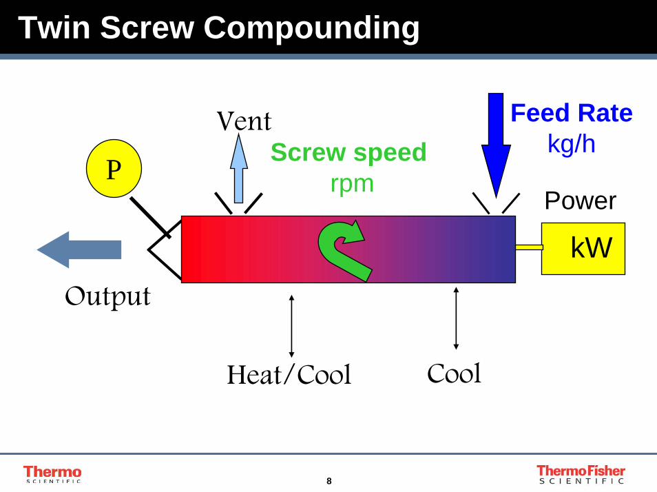
Twin Screw Compounding
Power
Screw speedrpm
Output
Feed Ratekg/h
Vent
P
kW
Heat/Cool Cool

9
Variables in Twin Screw Processing
DispersionColourDegradation
Screw designDie designBarrel layout
Step change
ContinuousSecondary
Screw speedFeed ratePrimary
Independent
variablesBarrel temp
Shear RateTemperatureResidence Time
Quality Control parameters
Process parameters
Dependent
variables

10
Twin Screw Torque
100% Torque
Q max
Feed
Rat
e, k
g/hr
Screw Speed, rpm N. max
High energy
configuration
Low energy
configuration

11
Segmented Twin Screw Elements
12
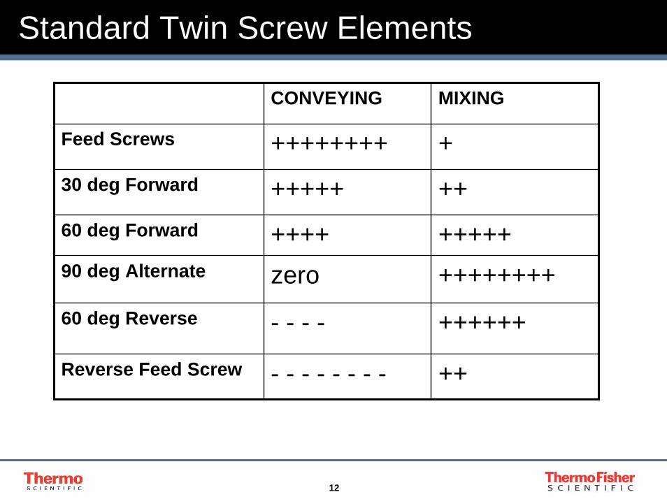
Standard Twin Screw Elements
CONVEYING MIXING
Feed Screws ++++++++ +30 deg Forward +++++ ++60 deg Forward ++++ +++++90 deg Alternate zero ++++++++60 deg Reverse - - - - ++++++
Reverse Feed Screw - - - - - - - - ++
13
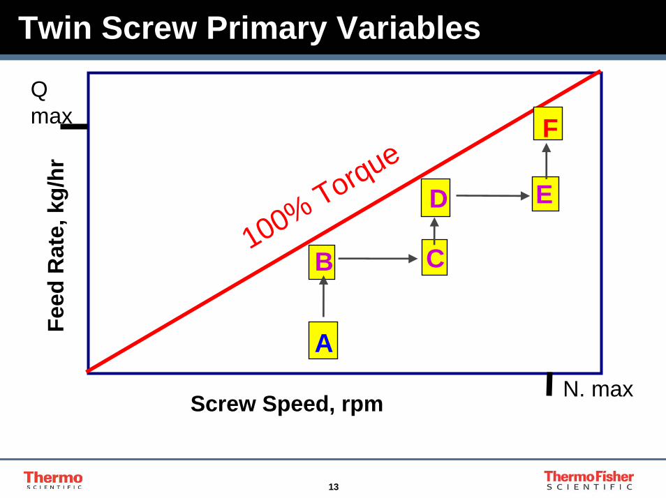
Twin Screw Primary Variables
100% Torque
Q max
Feed
Rat
e, k
g/hr
Screw Speed, rpm N. max
A
B C
D
F
E

14
Experimental outline
Approx Feedrate Outline16mm 24mm
100%6 20 X 90%
5 16 X X 80%
4 12 X X X 60%
3 8 X X X X 40%
1.5 4 X X X X X 20%200 400 600 800 1000
RPM

15
Equipment
1. Twin screw melting and Mixing Process
2. 16mm and 24mm twin screw compounders.
3. Use of Specific Energy Input to predict performance
4. Relationship between screw speed and feed rate and their effect on :-
- Energy Input- Residence Time- Degree of Fill
5. Scale-up and heat transfer
16
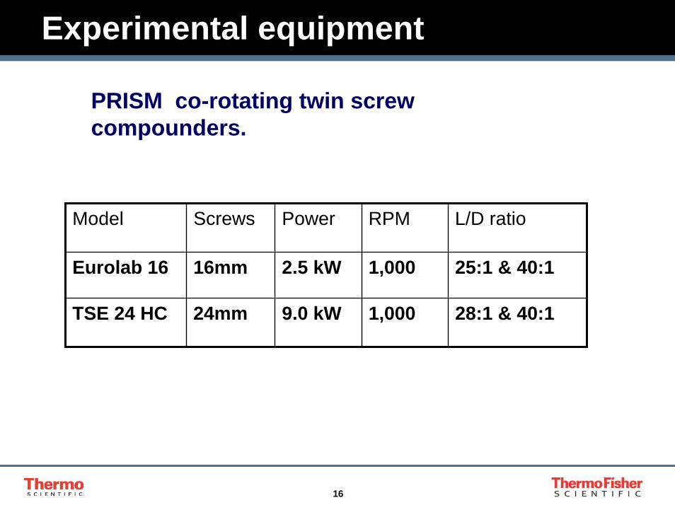
Experimental equipment
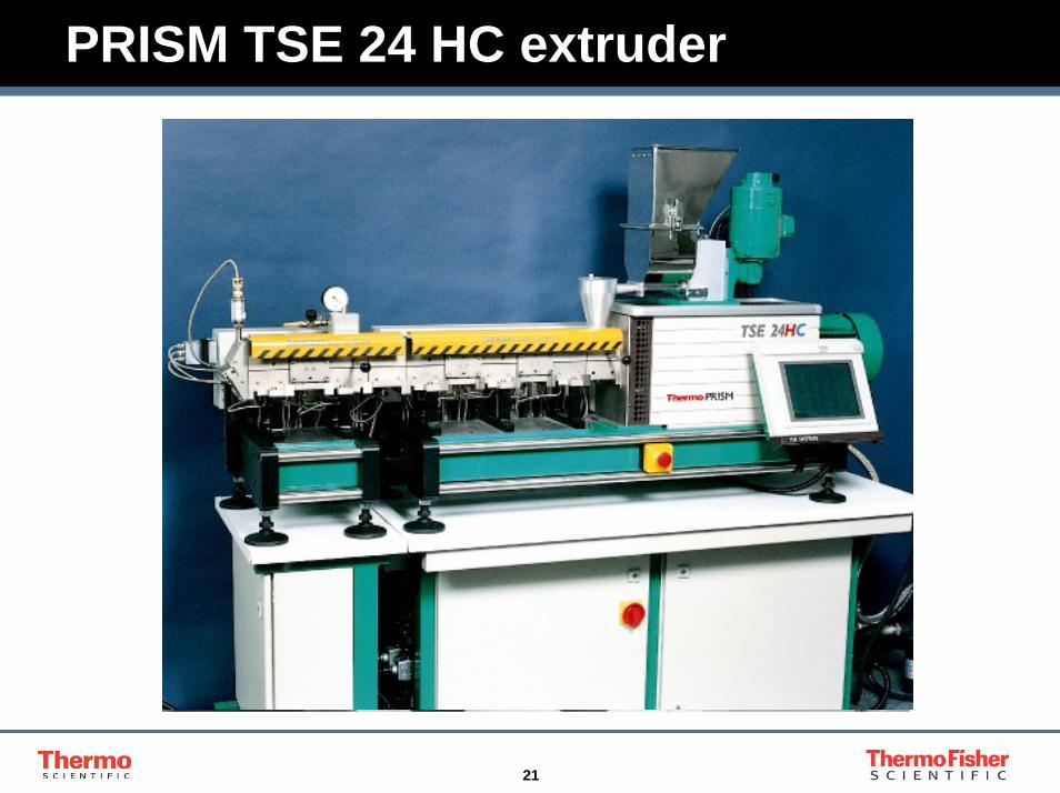
PRISM co-rotating twin screw compounders.
Model Screws Power RPM L/D ratio
Eurolab 16 16mm 2.5 kW 1,000 25:1 & 40:1
TSE 24 HC 24mm 9.0 kW 1,000 28:1 & 40:1

17
Twin screw configurations 16mm
Eurolab 16 25:1One and Two stage
configuration
0
0.2
0.4
0.6
0.8
1
1.2
1.4
0 200 400 600 800 1000 1200RPM
Net
t Pow
er k
W
3.54 kg/h 2 stage 3.54 kg/h 1 stage6.27 kg/h 1 stage 6.27 kg/h 2 stage

18
Twin screw configurations 16mm
16 m m 25:1 L/D
16 m m 40:1 L/D
CONVEYING M IXING CONVEYING M IXING CONVEYING
678910ZONEZONEZONEZONEZONEZONEZONEZONEZONEZONE
6 25 4 3 1COOLED
ZONE ZONEZONE ZONE ZONE ZONE
FEED
FEED
OPENDISCHARGE
CONVEYING CONVEYING M IXING
COOLED
1
CONVEYINGM IXING
2345
19
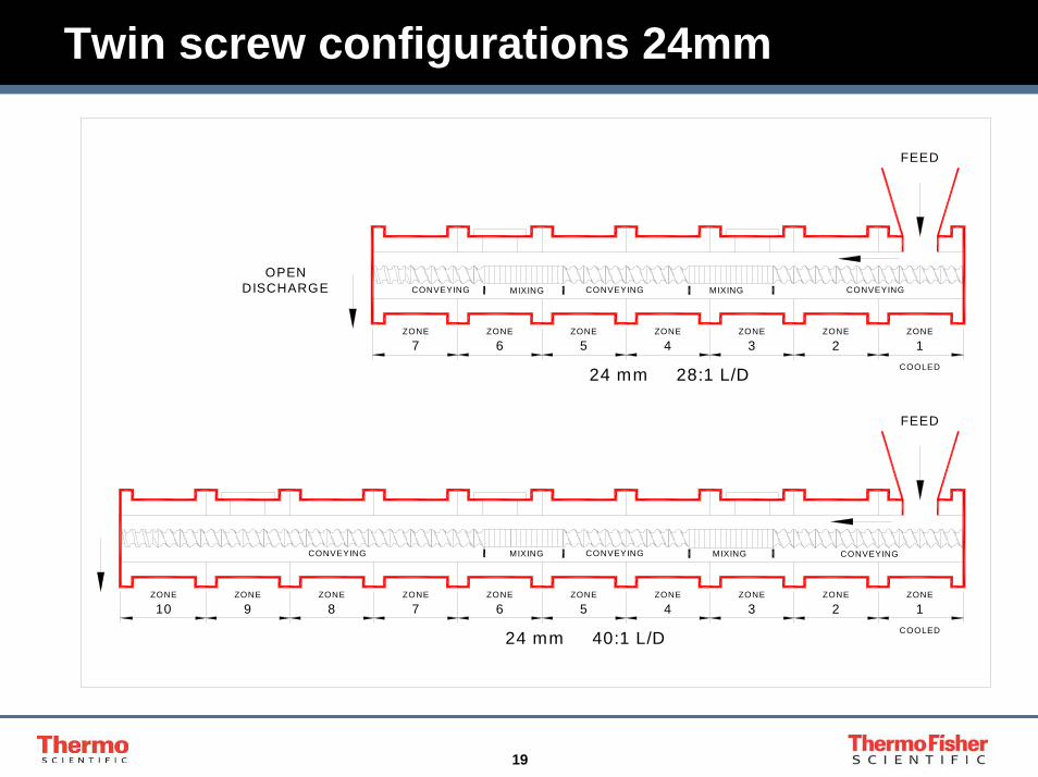
Twin screw configurations 24mm
FEED
OPENDISCHARGE
24 mm 28:1 L/D
24 mm 40:1 L/D
FEED
MIXING
ZONE
4ZONE
5
CONVEYING
ZONE
3
MIXING
2ZONE ZONE
1
CONVEYING
CONVEYING
COOLED
COOLED
ZONE
7
CONVEYING
ZONE
6ZONE
CONVEYING
ZONE
5
MIXING
4ZONE ZONE
3
MIXING
2ZONE
1
ZONEZONE
10
CONVEYING
9ZONE ZONE
8ZONE
7 6

20
PRISM Eurolab 16 extruder
21
PRISM TSE 24 HC extruder
22
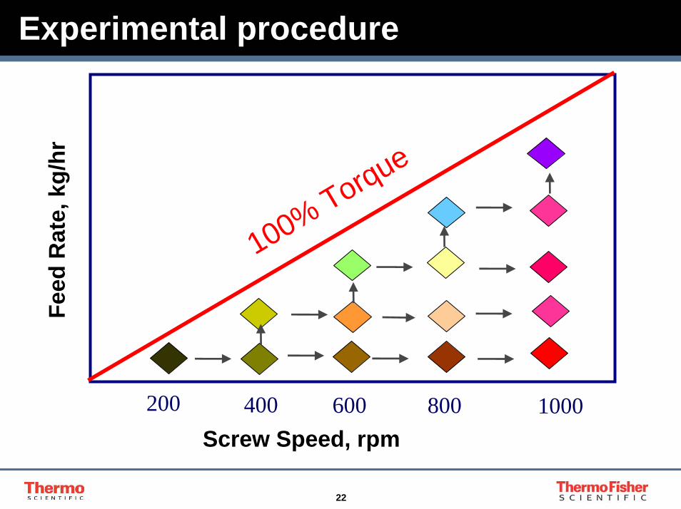
Experimental procedure
100% Torque
Feed
Rat
e, k
g/hr
200 400 600 1000800Screw Speed, rpm
23
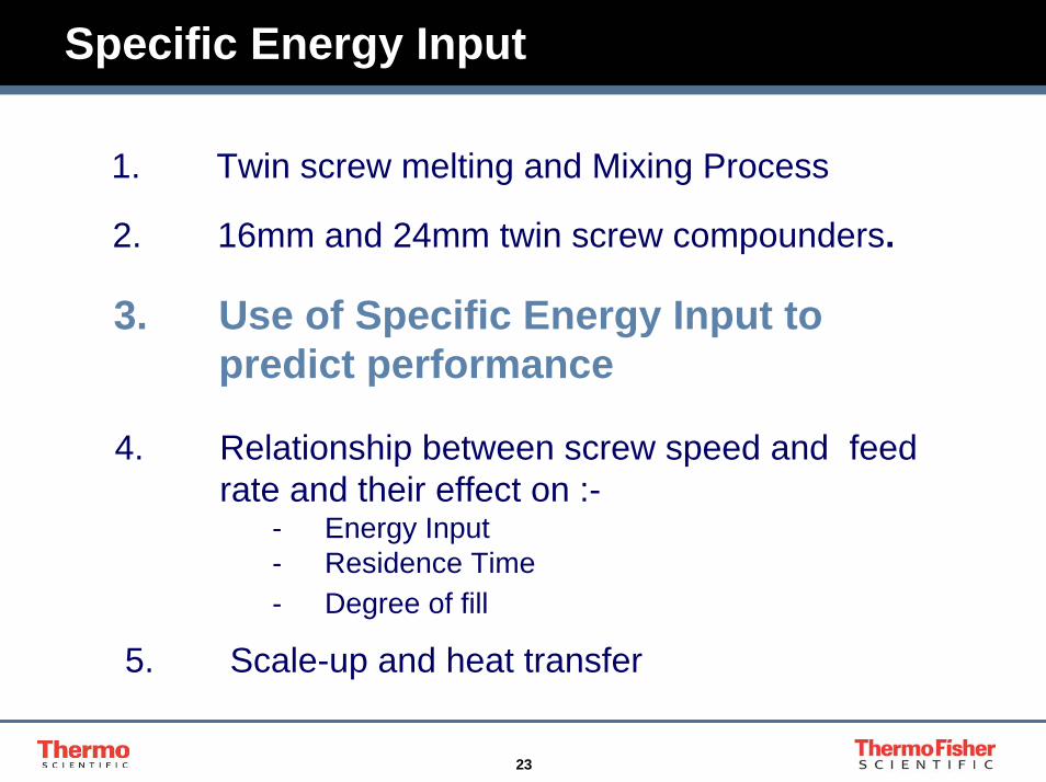
Specific Energy Input
1. Twin screw melting and Mixing Process
2. 16mm and 24mm twin screw compounders.
3. Use of Specific Energy Input to predict performance
4. Relationship between screw speed and feed rate and their effect on :-
- Energy Input- Residence Time- Degree of fill
5. Scale-up and heat transfer
24
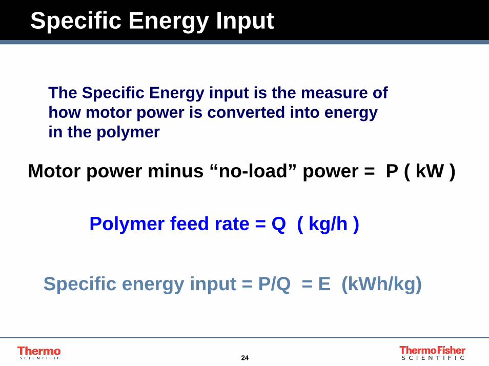
Specific Energy Input
The Specific Energy input is the measure of how motor power is converted into energy in the polymer
Motor power minus “no-load” power = P ( kW )
Polymer feed rate = Q ( kg/h )
Specific energy input = P/Q = E (kWh/kg)

25
Scale-up by Specific Energy Input
The Specific Energy value allows a calculation of what motor power is required to process a defined quantity of Material.
Required Polymer Output = Q ( kg/h )
Specific energy input = E (kWh/kg)
Nett Motor power P = Q x E ( kW )
26
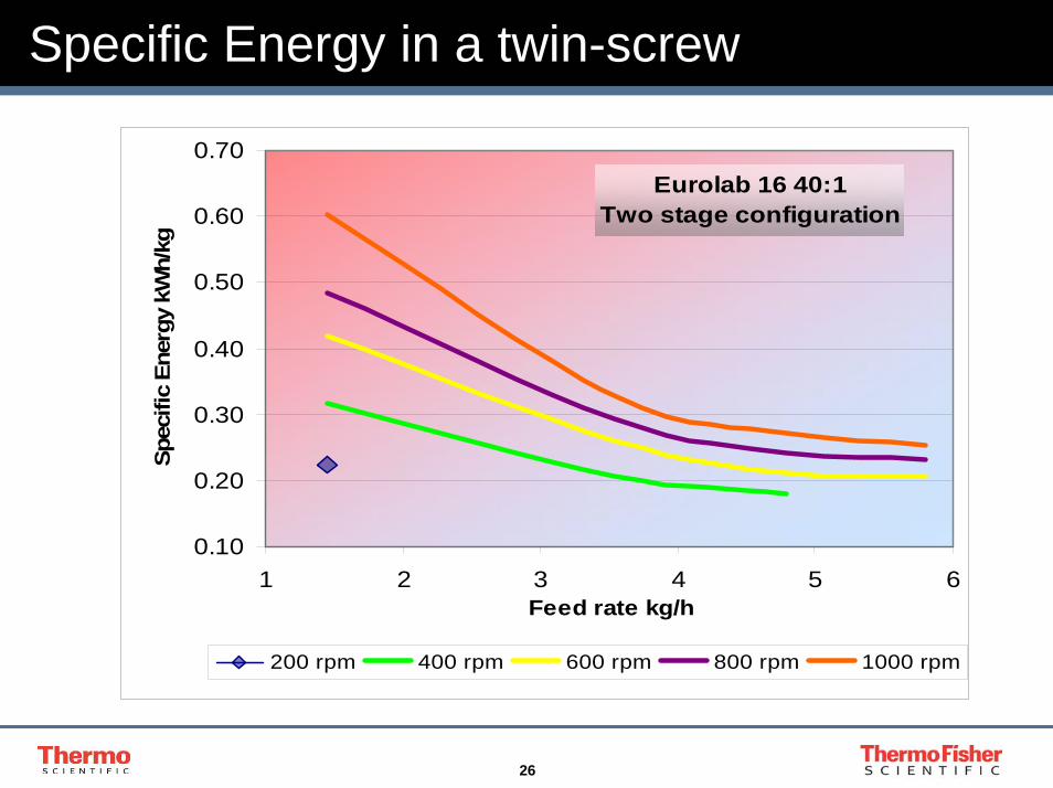
Specific Energy in a twin-screw
Eurolab 16 40:1 Two stage configuration
0.10
0.20
0.30
0.40
0.50
0.60
0.70
1 2 3 4 5 6Feed rate kg/h
Spec
ific
Ener
gy k
Wh/
kg
200 rpm 400 rpm 600 rpm 800 rpm 1000 rpm
27
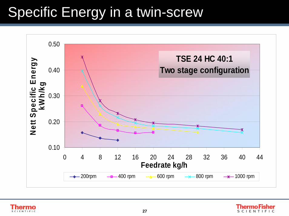
Specific Energy in a twin-screw
TSE 24 HC 40:1 Two stage configuration
0.10
0.20
0.30
0.40
0.50
0 4 8 12 16 20 24 28 32 36 40 44Feedrate kg/h
Net
t Spe
cific
Ene
rgy
kWh/
kg
200rpm 400 rpm 600 rpm 800 rpm 1000 rpm
28
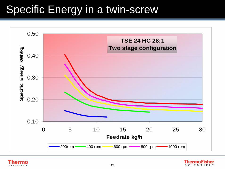
Specific Energy in a twin-screw
TSE 24 HC 28:1 Two stage configuration
0.10
0.20
0.30
0.40
0.50
0 5 10 15 20 25 30Feedrate kg/h
Spec
ific
Ene
rgy
kW
h/kg
200rpm 400 rpm 600 rpm 800 rpm 1000 rpm

29
Effect of Screw Speed
TSE 24 HC 40:1 Two stage configuration
0.00
0.10
0.20
0.30
0.40
0.50
0 200 400 600 800 1000RPM
Net
t Spe
cific
Ene
rgy
kWh/
kg
4 kg/h 8 kg/h 12 kg/h 16 kg/h 20 kg/h 30 kg/h 40 kg/h
30
Introduction
1. Twin screw melting and Mixing Process
2. 16mm and 24mm twin screw compounders.
3. Use of Specific Energy Input to predict performance
4. Relationship between screw speed and feed rate and their effect on :-
- Energy Input- Residence Time- Degree of Fill
5. Scale-up and heat transfer
31
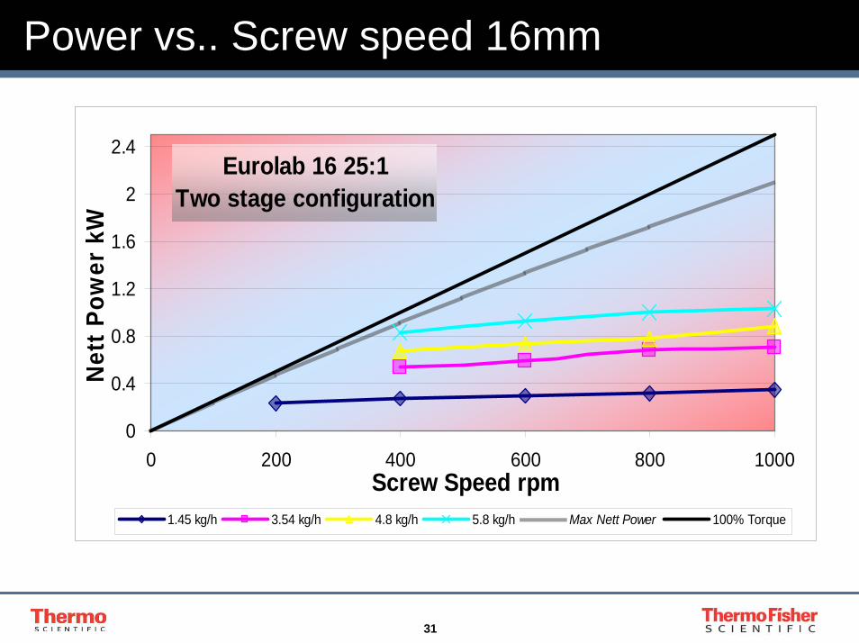
Power vs.. Screw speed 16mm
Eurolab 16 25:1Two stage configuration
0
0.4
0.8
1.2
1.6
2
2.4
0 200 400 600 800 1000Screw Speed rpm
Net
t Pow
er k
W
1.45 kg/h 3.54 kg/h 4.8 kg/h 5.8 kg/h Max Nett Power 100% Torque
32
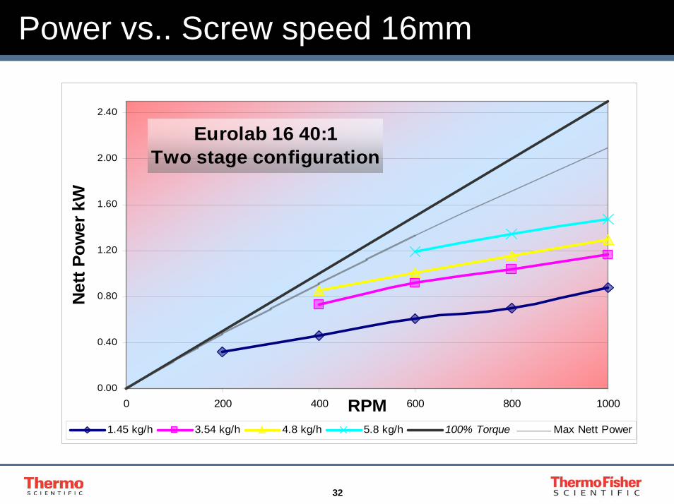
Power vs.. Screw speed 16mm
Eurolab 16 40:1Two stage configuration
0.00
0.40
0.80
1.20
1.60
2.00
2.40
0 200 400 600 800 1000RPM
Net
t Pow
er k
W
1.45 kg/h 3.54 kg/h 4.8 kg/h 5.8 kg/h 100% Torque Max Nett Power

33
Power vs. Screw speed 24mm 28:1
TSE 24 HC 28:1Two stage configuration
0.00
1.00
2.00
3.00
4.00
5.00
6.00
7.00
8.00
9.00
0 200 400 600 800 1000Screw speed rpm
Net
t Pow
er k
W
4 kg/h 8 kg/h 16 kg/h 20 kg/h
30 kg/h 100 % Torque Max Nett Power
34
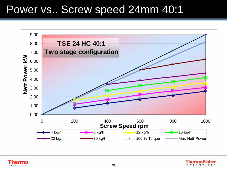
Power vs.. Screw speed 24mm 40:1
TSE 24 HC 40:1 Two stage configuration
0.00
1.00
2.00
3.00
4.00
5.00
6.00
7.00
8.00
9.00
0 200 400 600 800 1000Screw Speed rpm
Net
t Pow
er k
W
4 kg/h 8 kg/h 12 kg/h 16 kg/h20 kg/h 30 kg/h 100 % Torque Max Nett Power
35
Introduction
1. Twin screw melting and Mixing Process
2. 16mm and 24mm twin screw compounders.
3. Use of Specific Energy Input to predict performance
4. Relationship between screw speed and feed rate and their effect on :-
- Energy Input- Residence Time- Degree of Fill
5. Scale-up and heat transfer

36
Residence time in a twin-screw
TSE 24 HC 28:1 Two stage configuration
0
4
8
12
16
20
24
28
32
0 10 20 30 40 50
Residence time secs
Feed
rate
kg/
h
200rpm 400 rpm 600 rpm 800 rpm 1000 rpm
37
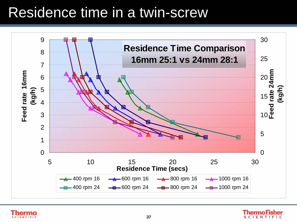
Residence time in a twin-screw
Residence Time Comparison16mm 25:1 vs 24mm 28:1
0
1
2
3
4
5
6
7
8
9
5 10 15 20 25 30Residence Time (secs)
Feed
rate
16m
m
(kg/
h)
0
5
10
15
20
25
30
Feed
rate
24m
m
(kg/
h)
400 rpm 16 600 rpm 16 800 rpm 16 1000 rpm 16400 rpm 24 600 rpm 24 800 rpm 24 1000 rpm 24
38
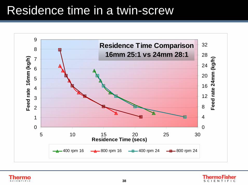
Residence time in a twin-screw
Residence Time Comparison16mm 25:1 vs 24mm 28:1
0
1
2
3
4
5
6
7
8
9
5 10 15 20 25 30Residence Time (secs)
Feed
rate
16m
m (k
g/h)
0
4
8
12
16
20
24
28
32
Feed
rate
24m
m (k
g/h)
400 rpm 16 800 rpm 16 400 rpm 24 800 rpm 24
39
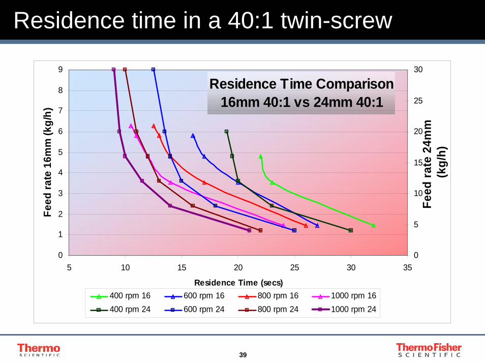
Residence time in a 40:1 twin-screw
Residence Time Comparison16mm 40:1 vs 24mm 40:1
0
1
2
3
4
5
6
7
8
9
5 10 15 20 25 30 35
Residence Time (secs)
Feed
rate
16m
m (k
g/h)
0
5
10
15
20
25
30
Feed
rate
24m
m
(kg/
h)
400 rpm 16 600 rpm 16 800 rpm 16 1000 rpm 16400 rpm 24 600 rpm 24 800 rpm 24 1000 rpm 24

40
Residence time in a 40:1 twin-screw
Residence Time Comparison16mm 40:1 vs 24mm 40:1
0
1
2
3
4
5
6
7
8
9
5 10 15 20 25 30 35Residence Time (secs)
Feed
rate
16m
m (k
g/h)
0
5
10
15
20
25
30
Feed
rate
24m
m (k
g/h)
400 rpm 16 800 rpm 16 400 rpm 24 800 rpm 24

41
Effect of Barrel length 4 kg/h
TSE 24 HC 28:1 and 40:1Two stage configuration
4 kg/h
200 rpm 28
400 rpm 28
600 rpm 28
800 rpm 28
1000 rpm 28
200 rpm 40
400 rpm 40
600 rpm 40
800 rpm 40
1000 rpm 40
0 5 10 15 20 25 30 35 40 45 50
1
Residence time secs
42
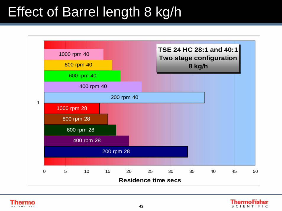
Effect of Barrel length 8 kg/h
TSE 24 HC 28:1 and 40:1Two stage configuration
8 kg/h
200 rpm 28
400 rpm 28
800 rpm 28
1000 rpm 28
200 rpm 40
400 rpm 40
600 rpm 40
1000 rpm 40
600 rpm 28
800 rpm 40
0 5 10 15 20 25 30 35 40 45 50
1
Residence time secs
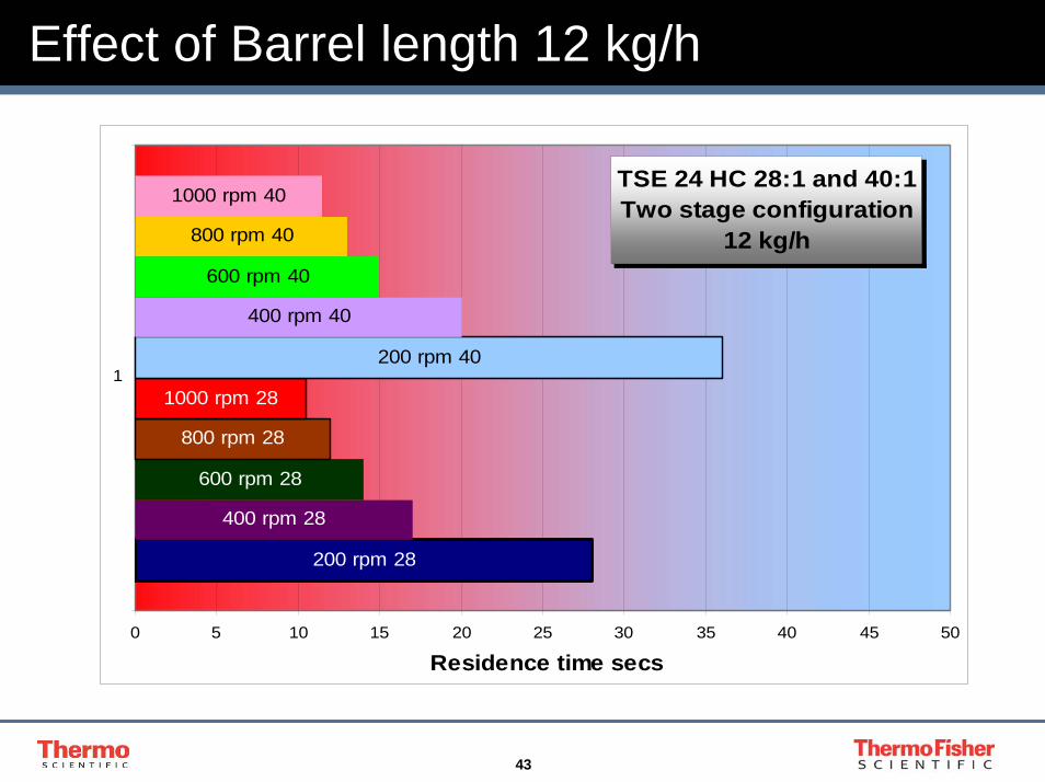
43
Effect of Barrel length 12 kg/h
TSE 24 HC 28:1 and 40:1Two stage configuration
12 kg/h
400 rpm 28
600 rpm 28
800 rpm 28
1000 rpm 28
200 rpm 40
400 rpm 40
600 rpm 40
800 rpm 40
200 rpm 28
1000 rpm 40
0 5 10 15 20 25 30 35 40 45 50
1
Residence time secs
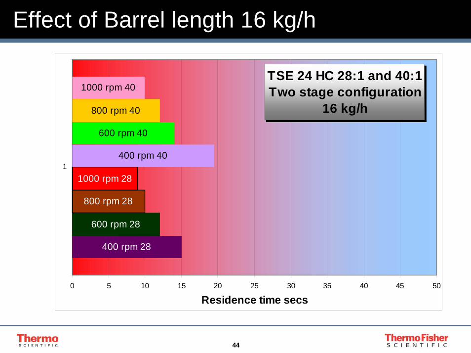
44
Effect of Barrel length 16 kg/h
TSE 24 HC 28:1 and 40:1Two stage configuration
16 kg/h
400 rpm 28
600 rpm 28
800 rpm 28
1000 rpm 28
400 rpm 40
600 rpm 40
800 rpm 40
1000 rpm 40
0 5 10 15 20 25 30 35 40 45 50
1
Residence time secs
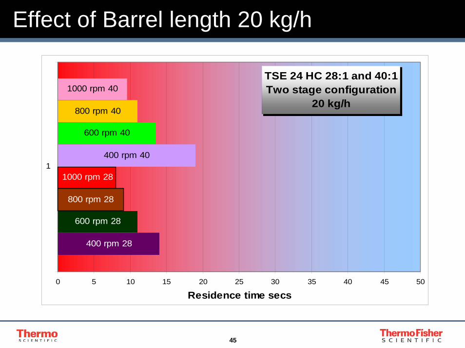
45
Effect of Barrel length 20 kg/h
TSE 24 HC 28:1 and 40:1Two stage configuration
20 kg/h
400 rpm 28
600 rpm 28
800 rpm 28
1000 rpm 28
400 rpm 40
600 rpm 40
800 rpm 40
1000 rpm 40
0 5 10 15 20 25 30 35 40 45 50
1
Residence time secs
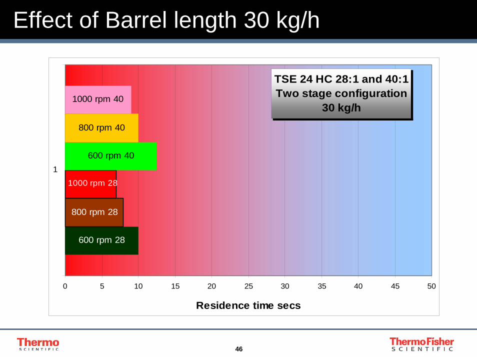
46
Effect of Barrel length 30 kg/h
TSE 24 HC 28:1 and 40:1Two stage configuration
30 kg/h
600 rpm 28
800 rpm 28
1000 rpm 28
600 rpm 40
800 rpm 40
1000 rpm 40
0 5 10 15 20 25 30 35 40 45 50
1
Residence time secs
47
Introduction
1. Twin screw melting and Mixing Process
2. 16mm and 24mm twin screw compounders.
3. Use of Specific Energy Input to predict performance
4. Relationship between screw speed and feed rate and their effect on :-
- Energy Input- Residence Time- Degree of Fill
5. Scale-up and heat transfer
48
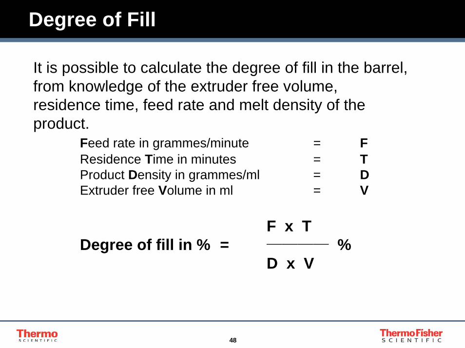
Degree of Fill
It is possible to calculate the degree of fill in the barrel, from knowledge of the extruder free volume, residence time, feed rate and melt density of the product.
Feed rate in grammes/minute = FResidence Time in minutes = TProduct Density in grammes/ml = DExtruder free Volume in ml = V
F x TDegree of fill in % = ──── %
D x V
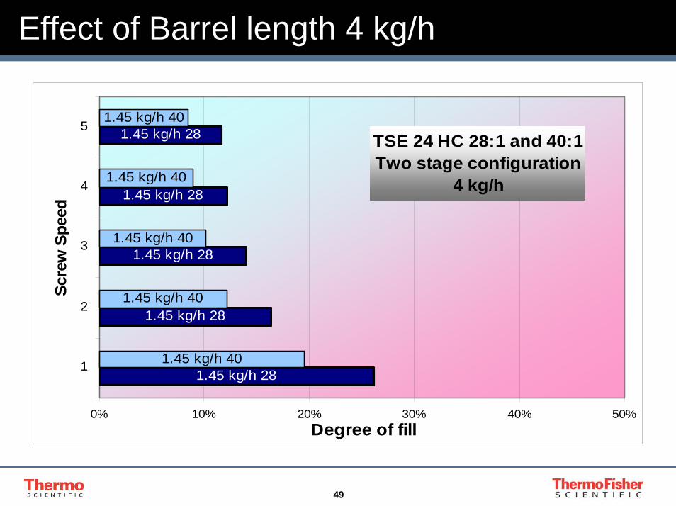
49
Effect of Barrel length 4 kg/h
TSE 24 HC 28:1 and 40:1Two stage configuration
4 kg/h
1.45 kg/h 28
1.45 kg/h 28
1.45 kg/h 28
1.45 kg/h 28
1.45 kg/h 28
1.45 kg/h 40
1.45 kg/h 40
1.45 kg/h 40
1.45 kg/h 40
1.45 kg/h 40
0% 10% 20% 30% 40% 50%
1
2
3
4
5
Scre
w S
peed
Degree of fill
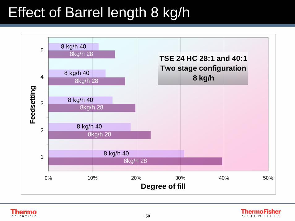
50
Effect of Barrel length 8 kg/h
TSE 24 HC 28:1 and 40:1Two stage configuration
8 kg/h
8kg/h 28
8kg/h 28
8kg/h 28
8kg/h 28
8kg/h 28
8 kg/h 40
8 kg/h 40
8 kg/h 40
8 kg/h 40
8 kg/h 40
0% 10% 20% 30% 40% 50%
1
2
3
4
5
Feed
setti
ng
Degree of fill

51
Effect of Barrel length 12 kg/h
TSE 24 HC 28:1 and 40:1Two stage configuration
12 kg/h
12 kg/h 28
12 kg/h 28
12 kg/h 28
12 kg/h 28
12 kg/h 28
12 kg/h 40
12 kg/h 40
12 kg/h 40
12 kg/h 40
12 kg/h 40
0% 10% 20% 30% 40% 50%
1
2
3
4
5
Scre
w s
peed
Degree of fill
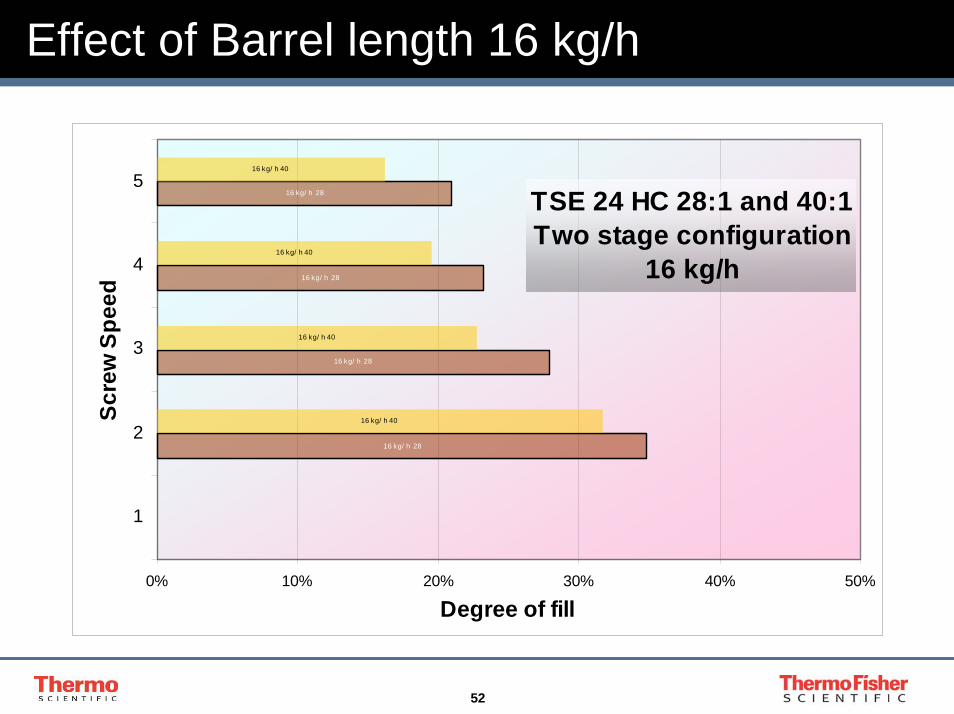
52
Effect of Barrel length 16 kg/h
TSE 24 HC 28:1 and 40:1Two stage configuration
16 kg/h
16 kg/ h 28
16 kg/ h 28
16 kg/ h 28
16 kg/ h 28
16 kg/ h 40
16 kg/ h 40
16 kg/ h 40
16 kg/ h 40
0% 10% 20% 30% 40% 50%
1
2
3
4
5
Scre
w S
peed
Degree of fill

53
Effect of Barrel length 20 kg/h
TSE 24 HC 28:1 and 40:1Two stage configuration
20 kg/h
20 kg/h 28
20 kg/h 28
20 kg/h 28
20 kg/h 28
2 kg/h 40
2 kg/h 40
2 kg/h 40
2 kg/h 40
0% 10% 20% 30% 40% 50%
1
2
3
4
5
Scre
w S
peed
Degree of fill
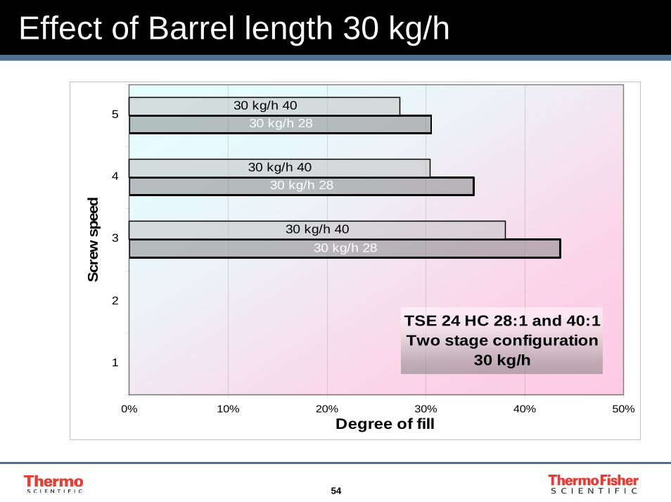
54
Effect of Barrel length 30 kg/h
TSE 24 HC 28:1 and 40:1Two stage configuration
30 kg/h
30 kg/h 28
30 kg/h 28
30 kg/h 28
30 kg/h 40
30 kg/h 40
30 kg/h 40
0% 10% 20% 30% 40% 50%
1
2
3
4
5
Scre
w s
peed
Degree of fill
55
Scale-up
1. Twin screw melting and Mixing Process2. 16mm and 24mm twin screw compounders.
3. Use of Specific Energy Input to predict performance
4. Relationship between screw speed and feed rate and their effect on :-
- Energy Input- Residence Time- Degree of Fill
5. Scale-up and heat transfer
56
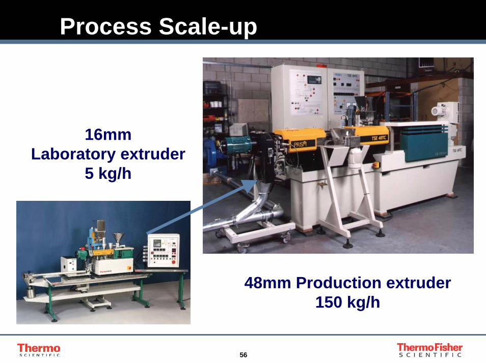
Process Scale-up
16mm Laboratory extruder
5 kg/h
48mm Production extruder150 kg/h
57
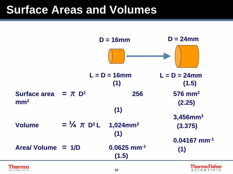
Surface Areas and Volumes
D = 24mmD = 16mm
L = D = 16mm(1)
L = D = 24mm(1.5)
Surface area = π D2 256 mm2
(1)
Volume = ¼ π D2 L 1,024mm3
(1)
Area/ Volume = 1/D 0.0625 mm-1
(1.5)
576 mm2
(2.25)
3,456mm3
(3.375)
0.04167 mm-1
(1)

58
Adiabatic Operation
1. Set extruder barrel temperatures to match melting point of polymers to be processed.
2. Begin extrusion, and monitor temperatures within the extruder, or at the discharge.
3. Align barrel temperatures to match the measured melt temperatures.
4 If temperature level exceeds desired limits, modify process conditions of screw speed and feed rate.
5. If temperatures are still outside the limits, consider changes to the screw configuration.

59
Summary
1. Twin screw melting and Mixing Process
2. 16mm and 24mm twin screw compounders.
3. Use of Specific Energy Input to predict performance
4. Relationship between screw speed and feed rate and their effect on :-
• Energy Input- Residence Time- Degree of Fill
5. Scale-up and heat transfer
60
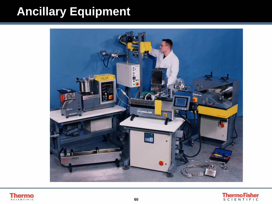
Ancillary Equipment

61
Conclusions1 Measuring Specific Energy Input on a laboratory scale extruder
allows prediction of performance of a production extruder, operating under similar conditions of screw speed and residence time.
2 At a fixed feed-rate, increasing screw speed will increase product specific energy and temperature, because of increased shear rate.
3 At a fixed screw speed, increasing feed-rate will reduceproduct specific energy and temperature, because of reduced residence time.
4 Increasing the L/D of an extruder will increase specific energy input, and residence time, even if the extra length is only conveying screws.
5 Operating a twin screw extruder adiabatically will avoid scale-up problems from differences in heat transfer

62
Acknowledgements
Wells Plastics in Stone for donation of the polymer used in the experiments
Jim McLatchie for assistance in collecting the data during the tests

63
New Opportunities To Work Together, With You
The world leader in serving science