Embed Size (px)
Citation preview
A Potable Biometric Access device using Dedicated Fingerprint Processor HATIM A. ABOALSAMH
Computer Science Department
King Saud University
P.O. Box 51178 , Riyadh 11543
Kingdom of Saudi Arabia
[email protected] http://faculty.ksu.edu.sa/aboalsamh
Abstract: Biometric signatures, or biometrics, are used to identify individuals by measuring certain unique physical
and behavioral characteristics. Individuals must be identified to allow or prohibit access to secure areas—or to enable
them to use personal digital devices such as, computer, personal digital assistant (PDA), or mobile phone. Virtually all
biometric methods are implemented using the following 1) sensor, to acquire raw biometric data from an individual;
2) feature extraction, to process the acquired data to develop a feature-set that represents the biometric trait; 3) pattern
matching, to compare the extracted feature-set against stored templates residing in a database; and 4) decision-
making, whereby a user’s claimed identity is authenticated or rejected. A typical access control system uses two
components. First component is a fingerprint reader that is connected to a database to match the pre stored fingerprints
with the one obtained by the reader. The second component is an RFID card that transmits information about the
person that requests an access. In this paper, a compact system that consists of a CMOS fingerprint sensor
(FPC1011F1) is used with the FPC2020 power efficient fingerprint processor ; which acts as a biometric sub-system
with a direct interface to the sensor as well as to an external flash memory for storing finger print templates. The small
size and low power consumption enables this integrated device to fit in smaller portable and battery powered devices
utilizing high performance identification speed. An RFID circuit is integrated with the sensor and fingerprint
processor to create an electronic identification card (e-ID card). The e-ID card will pre-store the fingerprint of the
authorized user. The RFID circuit is enabled to transmit data and allow access to the user, when the card is used and
the fingerprint authentication is successful.
Key-Words: Access control, RFID, Fingerprint processor, Fingerprint authentication, Biometrics.
1 Introduction Biometrics technology is based on
identification of individuals by a physical or
behavioural characteristic. Examples of
recognition of physical characteristics are:
fingerprints, iris, face or even hand geometry.
Behavioural characteristic can be the voice,
signature or other keystroke dynamics. What
make fingerprints idealistic for personal digital
identification is the fact that the fingerprint
pattern is composed of ridges and valleys that
form a unique combination of distinguishing
features of each finger (as shown in Fig. 1);
also, fingerprint characteristics do not vary in
time [1]. A comparison of popular biometrics
are shown in Tables 1 and 2. From the
comparison, it’s clear to see why fingerprint
biometrics is an attractive alternative in
comparison to other biometrics.
Table 1: Biometrics parameters explained
1 Universality each person should
have the
characteristic. 2 Uniqueness is how well the
biometric separates
individuals from
another. 3 Permanence measures how well a
biometric resists
aging and other
variance over time. 4 Collectability ease of acquisition
for measurement 5 Performance accuracy, speed, and
robustness of
technology used. 6 Acceptability degree of approval
of a technology. 7 Circumvention ease of use of a
substitute.
WSEAS TRANSACTIONS on COMPUTERS Hatim A. Aboalsamh
ISSN: 1109-2750 878 Issue 8, Volume 9, August 2010

Table 2: Comparison of biometric technologies
Biometrics Parameters
Biometrics 1 2 3 4 5 6 7
Face
high low med high low high low
Fingerprint
med high high med high med high
Hand
Geometry
med med med high med med med
Iris
high high high med high low high
Signature
low low low high low high low
Voice Print med low low med low high low
F.
Thermogram
high high low high med high high
Retinal Scan
high high med low high low high
Fig. 1: An illustration of Ridges and Valleys in
finger prints
A typical IC card access control system
combining fingerprint recognition, consists of
two input components : 1) an IC card reader to
read the stored information about the owner of
the card. 2) a fingerprint sensor to extract the
fingerprint patterns. The two inputs are moved
to the backend subsystem for identification [8],
as shown in Fig. 2.
Fig. 2: A typical fingerprint identification
system
New technologies introduced compact CMOS
fingerprint sensor, such as the FPC1011F1 with
several significant advantages:
a) Delivers superior image quality, with 256
gray scale values in every single pixel.
b) Ergonomically; the sensor component is
suitable for numerous types of
authentication systems.
c) Could be highly integrated with low power
solutions utilizing Fingerprint
microprocessor such as FPC2020 chip, or
a large variety of standard
microcontrollers.
A compact CMOS fingerprint sensor is used
with the FPC2020 fingerprint processor ;
which acts as a biometric sub-system with a
direct interface to the sensor and an external
flash memory for storing templates. The small
size and low power consumption of this system
enables it to be embedded in a Variety of
devices , such as, card readers, and smaller
portable devices without losing performance.
If The sensor and fingerprint processor could be
integrated with an RFID circuit to create an e-
ID card. The e-ID card will pre-store the fingerprint of the authorized user. When the card is used and the authentication is
WSEAS TRANSACTIONS on COMPUTERS Hatim A. Aboalsamh
ISSN: 1109-2750 879 Issue 8, Volume 9, August 2010
successful; the RFID circuit is enabled to transmit data and allow access to the user. Some of the useful Application for such a
device would be : Computer peripheral,
Physical access control, Time and attendance,
Wireless devices, Security application, and
Medical equipment & storage.
The idea of this e-ID card is to have a portable
authentication functionality as well as access
control through the RFID circuit; all in one
package in a credit card size devise.
2 System components
The system is divided into three main
components: the fingerprint sensor, the
fingerprint processor, and the RFID circuit.
2.1 The fingerprint sensor selection One of the most important tasks considering an
automatic fingerprint biometric recognition
system is the biometric pattern extraction from
the captured image of the fingerprint. Due to
imperfections of the acquired image, in some
cases certain pattern can be missed by the
extraction algorithm. Image imperfections can
also generate errors in determining the
coordinates of each true pattern and its relative
orientation of the image. All these facts make
remarkable decrease of the recognition system
reliability [7]. Thus, an efficient and reliable
fingerprint scanning apparatus is an essential
component of the whole system.
A capacitive sensor consists of a two
dimensional array of micro-capacitor plates
(this resembles image pixels) embedded in a
chip (see Fig. 5). The finger skin works as the
other side of each micro capacitor plate. Due to
distance variations from a ridge on the
fingerprint to the sensor and from a valley on
the fingerprint to the sensor; variations in
electrical charge will appear. This small
capacitance difference represents a 2D image of
the fingerprint, and is then used to acquire it
[9], as shown in Fig.3.
Fig. 3: Capacitive fingerprint sensor [9].
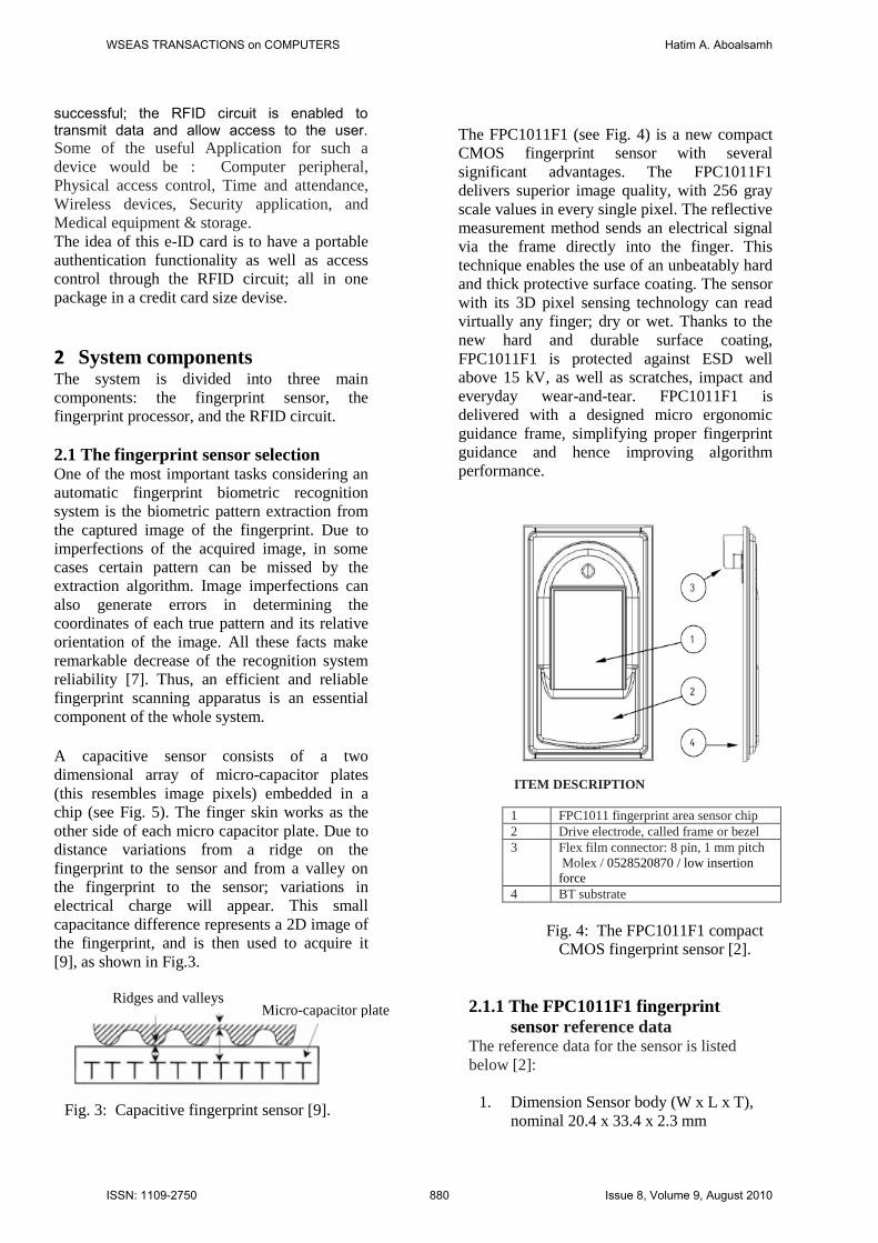
The FPC1011F1 (see Fig. 4) is a new compact
CMOS fingerprint sensor with several
significant advantages. The FPC1011F1
delivers superior image quality, with 256 gray
scale values in every single pixel. The reflective
measurement method sends an electrical signal
via the frame directly into the finger. This
technique enables the use of an unbeatably hard
and thick protective surface coating. The sensor
with its 3D pixel sensing technology can read
virtually any finger; dry or wet. Thanks to the
new hard and durable surface coating,
FPC1011F1 is protected against ESD well
above 15 kV, as well as scratches, impact and
everyday wear-and-tear. FPC1011F1 is
delivered with a designed micro ergonomic
guidance frame, simplifying proper fingerprint
guidance and hence improving algorithm
performance.
ITEM DESCRIPTION
1 FPC1011 fingerprint area sensor chip
2 Drive electrode, called frame or bezel
3 Flex film connector: 8 pin, 1 mm pitch
Molex / 0528520870 / low insertion
force
4 BT substrate
Fig. 4: The FPC1011F1 compact
CMOS fingerprint sensor [2].
2.1.1 The FPC1011F1 fingerprint
sensor reference data The reference data for the sensor is listed
below [2]:
1. Dimension Sensor body (W x L x T),
nominal 20.4 x 33.4 x 2.3 mm
Micro-capacitor plate
Ridges and valleys
WSEAS TRANSACTIONS on COMPUTERS Hatim A. Aboalsamh
ISSN: 1109-2750 880 Issue 8, Volume 9, August 2010
2. Interface Serial SPI 8 pin
3. Supply voltage VDC, typical 2.5 - 3.3
V
4. Supply current Typical at 3.3V, 4MHz
and RT (room temp) 7 mA
5. Supply current sleep mode Power
down, typical 10 μA
6. Clock frequency Serial SPI 32 MHz
7. Read out speed Serial SPI 4 Mpixel/s
8. Active sensing area Pixel matrix 10.64
x 14.00 Mm
9. Size sensing array Pixel matrix (363
dpi) 152 x 200 Pixel
10. Pixel resolution 256 gray scale values 8
Bit
11. ESD protection IEC61000-4-2, level 4,
air discharge > 15 kV
12. Wear-and-tear No of wear cycles at 6N
> 1 million Cycle
2.1.2 Architecture of the FPC1011F1
fingerprint sensor Package As shown in Fig. 5, the sensor package
consists of several vital components to read
the fingerprint and transform the reading into
a greyscale representation of the fingerprint.
The readout is then stored in a serial flash
memory as a template.
The sensor area is a matrix of 152x200
elements that represent pixels. Once the finger
is positioned over the sensor, a voltage is
supplied through the TX1 line. The voltage is
moved through the finger to the elements of
the sensor matrix. Each matrix will hold a
voltage value. Those values are deferent, since
they represent ridges and valleys of the
fingerprint. The sensor element values are
transferred in sequence through the X and Y
address registers. Each sensor element is
converted through an A/D circuit to a digital
value that represents a gray scale pixel (values
between 0 and 255). The pixels are then
transferred to a serial flash memory and
organized into a template. The memory
template represents a gray scale image of the
fingerprint [2].
Fig. 5: Architecture of the FPC1011F1
fingerprint sensor [2].
The sensor matrix consists of 152 x 200
sensor elements. The entire sensor, or a part of
it, is read by applying a read sensor
instruction. The size of the active area is set
by the values of the XSHIFT and YSHIFT
registers. The default values for these registers
select the complete sensor area to be read
once. The readout sequence is illustrated in
Fig. 6.During all read operations, 8 pixels are
captured simultaneously. By default the first
8pixels being read are pixel (0,0) to
(7,0),followed by pixels (8,0) to (15,0).
Fig. 6: The readout sequence of the
fingerprint sensor [2]
WSEAS TRANSACTIONS on COMPUTERS Hatim A. Aboalsamh
ISSN: 1109-2750 881 Issue 8, Volume 9, August 2010

2.2 The Fingerprint Processor
Selection Many systems attempted to create single
chip fingerprint recognition. An example of
such system is the Blackfin RISC processor
connected to the AT77C104B FingerChip IC
. In such a system the fingerChip Ic captures
the image of a fingerprint as the finger is
swept vertically over the sensor window.
This type of sensor is effective [11], but not
suitable ergonomically; since it require the
finger to be swapped over the sensor. This is
not practical for a card holder.
The Blackfin processor is a general purpose
processor; that means that an application
program to do the fingerprint image feature
extraction, and other necessary operation;
must be provided by the system designer.
This prompted us to search for a more
designer friendly system. Such a processor
will perform fingerprint image feature
extraction using one single command.
The FPC2020 is a small, fast and power
efficient ASIC that acts as a biometric sub-
system with a direct interface to the
FPC1011C sensor as well as to an external
flash memory for storing templates. Thanks
to its small size and low power consumption
it fits as well in door locks, card readers and
safes as in smaller portable and battery
powered devices without losing
identification speed or performance.
FPC2020 can easily be integrated into
virtually any application and be controlled
by a host sending basic commands for
enrolment and verification via the serial
interface. In a standalone configuration, the
processor is not connected to a host, in this
case; the application program is pre stored in
the FLASH memory connected to the
processor. At start-up of FPC2020, a boot
sequence (located in ROM) is executed,
which downloads the main application code
located in the attached FLASH memory. If
no errors are encountered during this
download process, the boot sequence
terminates and leaves control to the main
application. This is the default behaviour,
which typically always should occur in the
standard set-up. The boot sequence takes
180 ms. The Fingerprint templates are
created automatically and stored in flash
memory connected to FPC2020. Templates
used for verification can also be
uploaded/downloaded to an external storage,
e.g. central database, smart card or portable
flash memory. FPC2020 has no internal
limitation in number of templates it can
handle. Size of external flash memory will
set the limitation [3]. The pin out
configuration of FPC2020 processor is
shown in Fig. 7.
Fig. 7: The 64 pin out configuration of
FPC2020 processor [3].
2.2.1 The Finger Print Processors
instruction set The FPC2020 processor has over 80
instructions. The instruction set is divided
into (7) groups [3].:
1. Biometrics commands
2. Image transfer commands
3. Template Handling Commands
4. Algorithm setting Commands
5. Firmware Commands
6. Communication Commands
7. Other supplementary commands
The instructions from the first groups are listed,
and their description is shown in tables (3, 4, 5)
as an example [3].
WSEAS TRANSACTIONS on COMPUTERS Hatim A. Aboalsamh
ISSN: 1109-2750 882 Issue 8, Volume 9, August 2010

Table 3: Biometrics commands
BIOMETRIC
COMMANDS
HEX DESCRIPTION
API_CAPTURE_IMAGE 0x80 Capture image
from sensor (before enrol).
API_CAPTURE_AND_EN
ROL_RAM
0x81 Enrol into RAM (includes Capture
Image)
API_CAPTURE_AND_VE
RIFY_RAM
0x82 Verify against
RAM (includes
Capture Image)
API_CAPTURE_AND_VE
RIFY_FLASH
0x83 Verify against single FLASH slot
(includes Capture Image) Set slot
number in IDX
API_CAPTURE_AND_ID
ENTIFY_FLASH
0x84 Identify against all FLASH slots
(includes Capture
Image)
API_ENROL_RAM 0x85 Enrol into RAM
API_VERIFY_RAM 0x86 Verify against
RAM
API_VERIFY_FLASH 0x87 Verify against single FLASH slot
Set slot number in
IDX
API_IDENTIFY_FLASH 0x88 Identify against all FLASH slots
API_CAPTURE_IMAGE_
FINGERPRESENT
0x89 Capture Image
from sensor (once a finger is present)
API_ENROL_FLASH 0x92 Enrol into FLASH
memory
API_CAPTURE_AND_EN
ROL_FLASH
0x93 Enrol into FLASH memory (includes
Capture Image)
Table 4: Image transfer commands
IMAGE TRANSFER HEX DESCRIPTION
API_UPLOAD_IMAGE 0x90 Upload image from RAM
API_DOWNLOAD_IM
AGE
0x91 Download image to RAM
Table 5: Template handling commands
TEMPLATE HANDLING HEX DESCRIPTION
API_UPLOAD_TEMPLATE 0xA0 Upload template from
RAM
API_DOWNLOAD_TEMPLAT
E
0xA1 Download template to
RAM
API_COPY_TEMPLATE_RA
M_TO_FLASH
0xA2 Copy template from RAM
to permanent FLASH
storage Set slot number in
IDX
API_UPLOAD_TEMPLATE_F
ROM_FLASH
0xA3 Upload template from
single FLASH slot Set slot
number in IDX
API_DELETE_TEMPLATE_R
AM
0xA4 Erase template from RAM
API_DELETE_SLOT_IN_FLA
SH
0xA5 Delete single slot in
FLASH Set slot number in
IDX
API_DELETE_ALL_IN_FLAS
H
0xA6 Delete all FLASH slots
API_DOWNLOAD_TEMPLAT
E_TO_FLASH
0xA7 Download a template to
FLAS
3 The Application Program The application program is stored into the
auxiliary memory connected to the
fingerprint processor. The program start
executing once the finger is positioned
over the sensor package. The program
consists of instructions to read the sensor
area and match it with a pre stored
fingerprint template. If the pre stored
template matches the image in the sensor
area then the processor sends a signal to
enable the RFID circuit.
4 The RFID circuit
An RFID system consists of a transponder, a
reader and an antenna. The transponder
(transmitter –responder) device is commonly
WSEAS TRANSACTIONS on COMPUTERS Hatim A. Aboalsamh
ISSN: 1109-2750 883 Issue 8, Volume 9, August 2010
called the tag. The RFID reader is a
transceiver (transmitter – receiver) that has the
ability to transmit and receive radio signals
over the air. RFID tags come in three different
forms: active, passive, and semi-passive.
Table 6 shows RFID Class Structure.
The most common form of RFID tag is
passive. Passive tags do not have an
embedded power source and they hold up to
two kilobits of data. Semipassive and active
tags both have a power source in the form of a
battery. The battery source in a semi-passive
tag powers the circuitry when a reader
interrogates the tag whereas in active tags, the
battery source transmits data when
interrogated [10].
RFID tags come in a variety of different types
according to their functionality, and these
types have been defined in an RFID Class
Structure by the Auto-ID Centre (and later through EPC Global), which has been subsequently refined and built on. The basic
structure defines five classes in ascending
order as follows [4,5]:
Table 6: RFID class structure by the
Auto-ID Centre
5 RFID circuit used in this
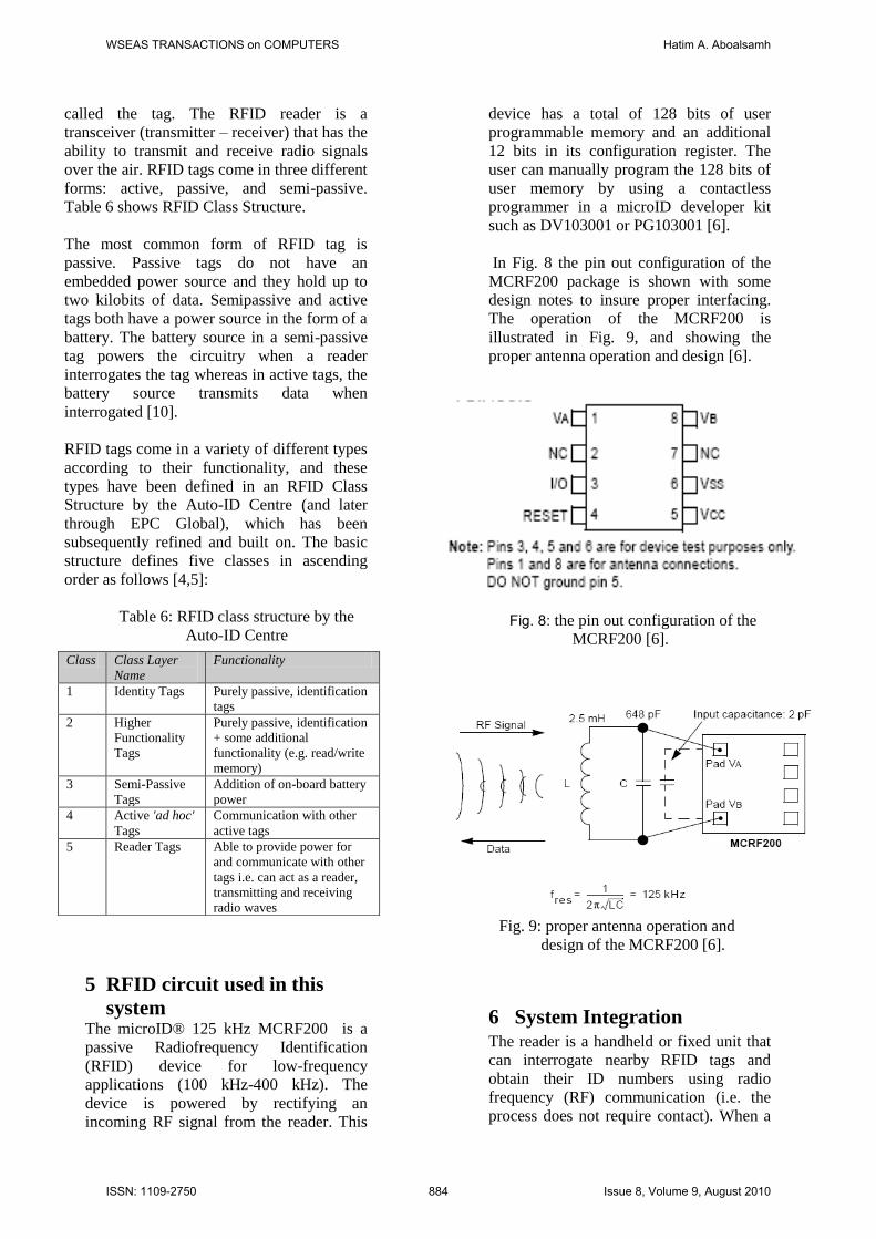
system The microID® 125 kHz MCRF200 is a
passive Radiofrequency Identification
(RFID) device for low-frequency
applications (100 kHz-400 kHz). The
device is powered by rectifying an
incoming RF signal from the reader. This
device has a total of 128 bits of user
programmable memory and an additional
12 bits in its configuration register. The
user can manually program the 128 bits of
user memory by using a contactless
programmer in a microID developer kit
such as DV103001 or PG103001 [6].
In Fig. 8 the pin out configuration of the
MCRF200 package is shown with some
design notes to insure proper interfacing.
The operation of the MCRF200 is
illustrated in Fig. 9, and showing the
proper antenna operation and design [6].
Fig. 8: the pin out configuration of the
MCRF200 [6].
Fig. 9: proper antenna operation and
design of the MCRF200 [6].
6 System Integration The reader is a handheld or fixed unit that
can interrogate nearby RFID tags and
obtain their ID numbers using radio
frequency (RF) communication (i.e. the
process does not require contact). When a
Class Class Layer
Name
Functionality
1 Identity Tags Purely passive, identification
tags
2 Higher
Functionality
Tags
Purely passive, identification
+ some additional
functionality (e.g. read/write
memory)
3 Semi-Passive
Tags
Addition of on-board battery
power
4 Active 'ad hoc'
Tags
Communication with other
active tags
5 Reader Tags Able to provide power for
and communicate with other
tags i.e. can act as a reader,
transmitting and receiving
radio waves
WSEAS TRANSACTIONS on COMPUTERS Hatim A. Aboalsamh
ISSN: 1109-2750 884 Issue 8, Volume 9, August 2010
passive tag is within range of a reader, the
tag’s antenna absorbs the energy being
emitted from the reader, directs the energy
to ‘fire up’ the integrated circuit on the tag,
which then uses the energy to beam back
the ID number and any other associated
information as shown in Fig. 7.
Fig. 7: System integration
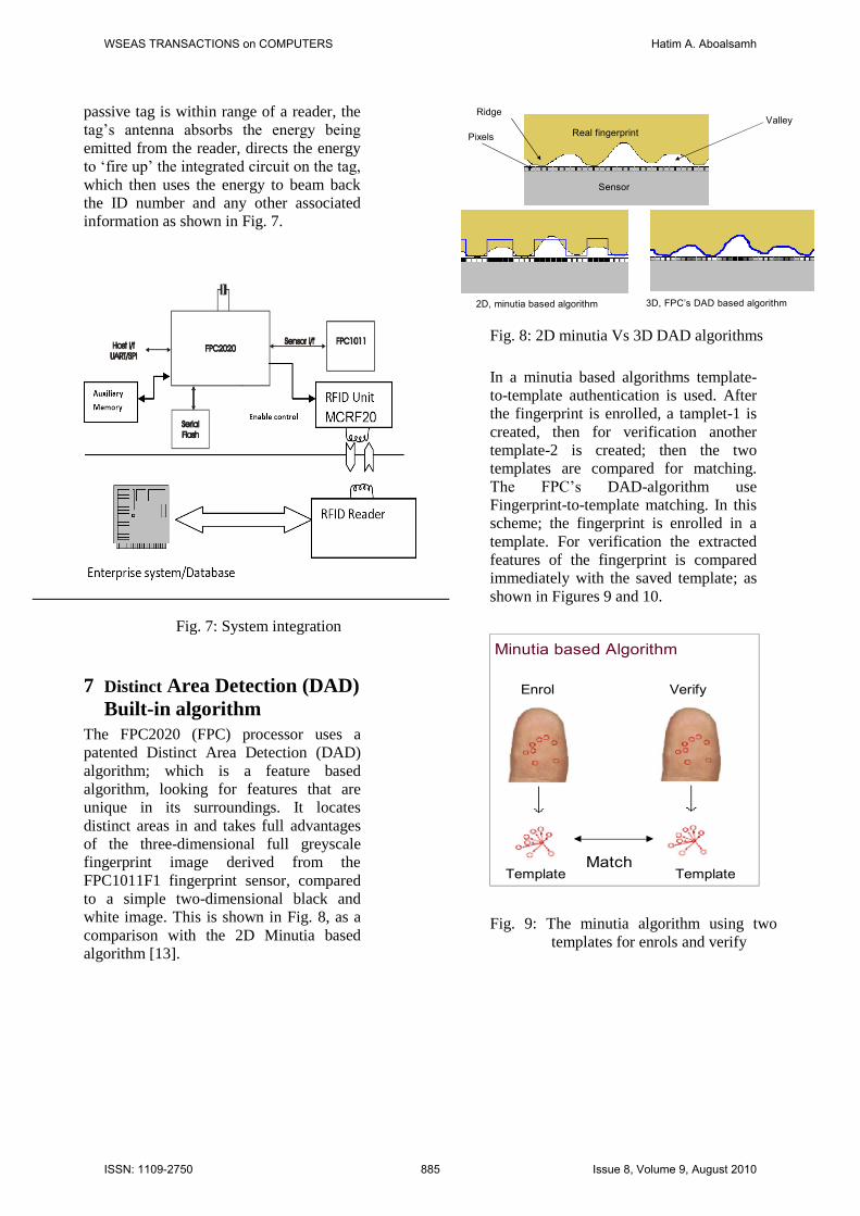
7 Distinct Area Detection (DAD)
Built-in algorithm
The FPC2020 (FPC) processor uses a
patented Distinct Area Detection (DAD)
algorithm; which is a feature based
algorithm, looking for features that are
unique in its surroundings. It locates
distinct areas in and takes full advantages
of the three-dimensional full greyscale
fingerprint image derived from the
FPC1011F1 fingerprint sensor, compared
to a simple two-dimensional black and
white image. This is shown in Fig. 8, as a
comparison with the 2D Minutia based
algorithm [13].
Algorithm – DAD vs. Minutia
Real fingerprint
2D, minutia based algorithm 3D, FPC’s DAD based algorithm
RidgeValley
Sensor
Pixels
Fig. 8: 2D minutia Vs 3D DAD algorithms
In a minutia based algorithms template-
to-template authentication is used. After
the fingerprint is enrolled, a tamplet-1 is
created, then for verification another
template-2 is created; then the two
templates are compared for matching.
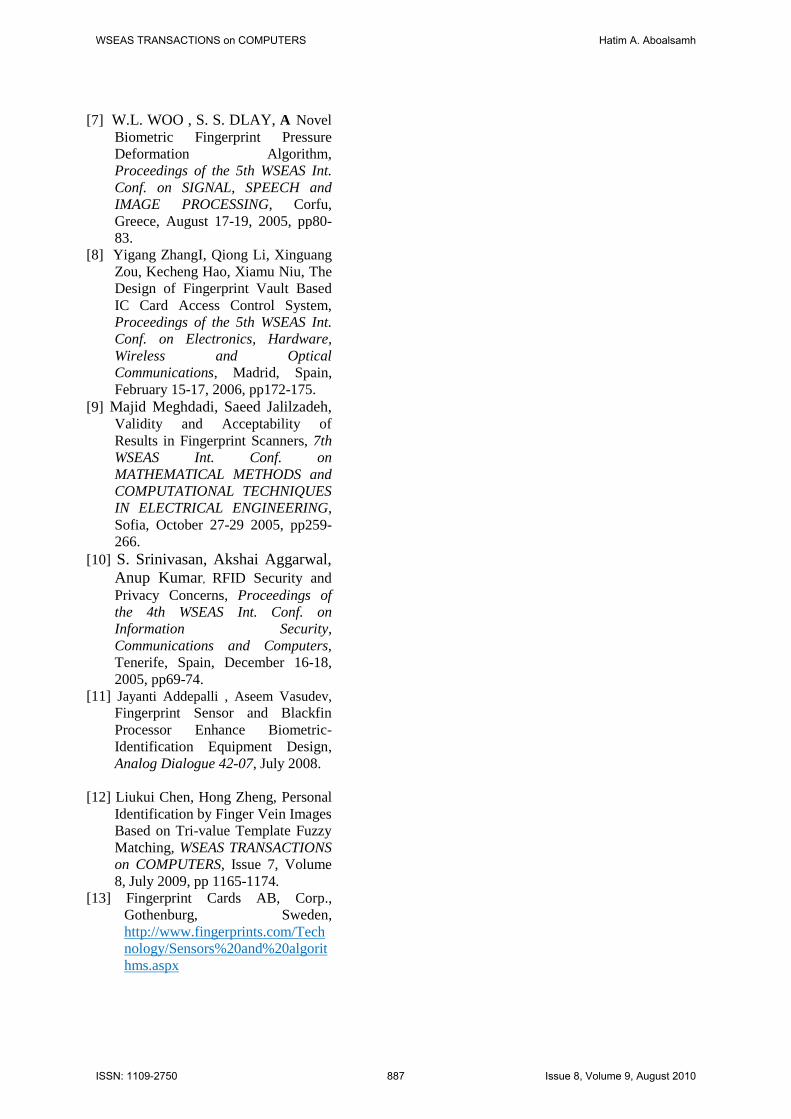
The FPC’s DAD-algorithm use
Fingerprint-to-template matching. In this
scheme; the fingerprint is enrolled in a
template. For verification the extracted
features of the fingerprint is compared
immediately with the saved template; as
shown in Figures 9 and 10.
Algorithm – DAD vs. Minutia
Match
Minutia based Algorithm
Enrol Verify
Template Template
Fig. 9: The minutia algorithm using two
templates for enrols and verify
WSEAS TRANSACTIONS on COMPUTERS Hatim A. Aboalsamh
ISSN: 1109-2750 885 Issue 8, Volume 9, August 2010
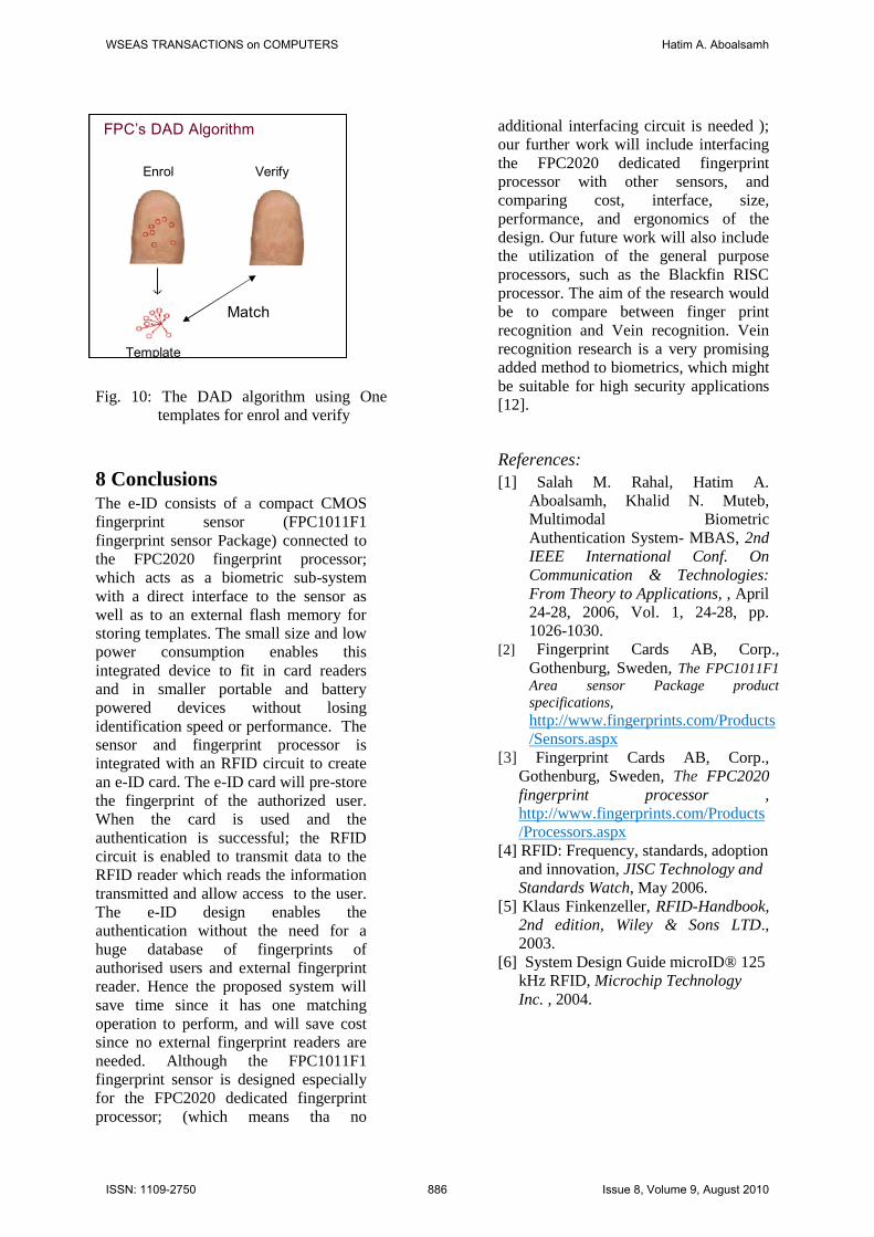
Fig. 10: The DAD algorithm using One
templates for enrol and verify
8 Conclusions The e-ID consists of a compact CMOS
fingerprint sensor (FPC1011F1
fingerprint sensor Package) connected to
the FPC2020 fingerprint processor;
which acts as a biometric sub-system
with a direct interface to the sensor as
well as to an external flash memory for
storing templates. The small size and low
power consumption enables this
integrated device to fit in card readers
and in smaller portable and battery
powered devices without losing
identification speed or performance. The
sensor and fingerprint processor is
integrated with an RFID circuit to create
an e-ID card. The e-ID card will pre-store
the fingerprint of the authorized user.
When the card is used and the
authentication is successful; the RFID
circuit is enabled to transmit data to the
RFID reader which reads the information
transmitted and allow access to the user.
The e-ID design enables the
authentication without the need for a
huge database of fingerprints of
authorised users and external fingerprint
reader. Hence the proposed system will
save time since it has one matching
operation to perform, and will save cost
since no external fingerprint readers are
needed. Although the FPC1011F1
fingerprint sensor is designed especially
for the FPC2020 dedicated fingerprint
processor; (which means tha no
additional interfacing circuit is needed );
our further work will include interfacing
the FPC2020 dedicated fingerprint
processor with other sensors, and
comparing cost, interface, size,
performance, and ergonomics of the
design. Our future work will also include
the utilization of the general purpose
processors, such as the Blackfin RISC
processor. The aim of the research would
be to compare between finger print
recognition and Vein recognition. Vein
recognition research is a very promising
added method to biometrics, which might
be suitable for high security applications
[12].
References:
[1] Salah M. Rahal, Hatim A.
Aboalsamh, Khalid N. Muteb,
Multimodal Biometric
Authentication System- MBAS, 2nd
IEEE International Conf. On
Communication & Technologies:
From Theory to Applications, , April
24-28, 2006, Vol. 1, 24-28, pp.
1026-1030.
[2] Fingerprint Cards AB, Corp.,
Gothenburg, Sweden, The FPC1011F1
Area sensor Package product
specifications,
http://www.fingerprints.com/Products
/Sensors.aspx
[3] Fingerprint Cards AB, Corp.,
Gothenburg, Sweden, The FPC2020
fingerprint processor ,
http://www.fingerprints.com/Products
/Processors.aspx
[4] RFID: Frequency, standards, adoption
and innovation, JISC Technology and
Standards Watch, May 2006.
[5] Klaus Finkenzeller, RFID-Handbook,
2nd edition, Wiley & Sons LTD.,
2003.
[6] System Design Guide microID® 125
kHz RFID, Microchip Technology
Inc. , 2004.
Algorithm – DAD vs. Minutia
Match
FPC’s DAD Algorithm
Enrol Verify
Template
WSEAS TRANSACTIONS on COMPUTERS Hatim A. Aboalsamh
ISSN: 1109-2750 886 Issue 8, Volume 9, August 2010
[7] W.L. WOO , S. S. DLAY, A Novel
Biometric Fingerprint Pressure
Deformation Algorithm,
Proceedings of the 5th WSEAS Int.
Conf. on SIGNAL, SPEECH and
IMAGE PROCESSING, Corfu,
Greece, August 17-19, 2005, pp80-
83.
[8] Yigang ZhangI, Qiong Li, Xinguang
Zou, Kecheng Hao, Xiamu Niu, The
Design of Fingerprint Vault Based
IC Card Access Control System,
Proceedings of the 5th WSEAS Int.
Conf. on Electronics, Hardware,
Wireless and Optical
Communications, Madrid, Spain,
February 15-17, 2006, pp172-175.
[9] Majid Meghdadi, Saeed Jalilzadeh, Validity and Acceptability of
Results in Fingerprint Scanners, 7th
WSEAS Int. Conf. on
MATHEMATICAL METHODS and
COMPUTATIONAL TECHNIQUES
IN ELECTRICAL ENGINEERING,
Sofia, October 27-29 2005, pp259-
266.
[10] S. Srinivasan, Akshai Aggarwal,
Anup Kumar, RFID Security and
Privacy Concerns, Proceedings of
the 4th WSEAS Int. Conf. on
Information Security,
Communications and Computers,
Tenerife, Spain, December 16-18,
2005, pp69-74.
[11] Jayanti Addepalli , Aseem Vasudev,
Fingerprint Sensor and Blackfin
Processor Enhance Biometric-
Identification Equipment Design,
Analog Dialogue 42-07, July 2008.
[12] Liukui Chen, Hong Zheng, Personal
Identification by Finger Vein Images
Based on Tri-value Template Fuzzy
Matching, WSEAS TRANSACTIONS
on COMPUTERS, Issue 7, Volume
8, July 2009, pp 1165-1174.
[13] Fingerprint Cards AB, Corp.,
Gothenburg, Sweden,
http://www.fingerprints.com/Tech
nology/Sensors%20and%20algorit
hms.aspx
WSEAS TRANSACTIONS on COMPUTERS Hatim A. Aboalsamh
ISSN: 1109-2750 887 Issue 8, Volume 9, August 2010


![Biometric Standards documents/Standards... · Biometric Profiles Biometric [Application] Profile – a conforming subset or combination of base standards used to effect specific biometric](https://img.dokumen.tips/doc/110x75/5f711372ce578d4ee02aea91/biometric-standards-documentsstandards-biometric-profiles-biometric-application.jpg)