Embed Size (px)
Citation preview

1
A Plan for Delivery of 8-GeV Protons through 2025 at Fermilab
R. Webber, W. Pellico, V. Lebedev, and D. McGinnis --- February 18, 2011
Executive Summary Every proton for the domestic United States High Energy Physics experimental program will be accelerated by the existing, now 40-year-old, Fermilab Linac and Booster until new machines are operational to replace them. Completion of the proposed Fermilab Project X accelerator is anticipated no sooner than 2020 for beams up to 3 GeV and well into that decade for beams at higher energy. The domestic High Energy Physics program for the next 15 years relies on the viability and vitality of the Fermilab Linac and Booster.
This document outlines a Proton Source Improvement Plan that begins to address the call by the Associate Director for Accelerators for “delivering 1.8E17 (8 GeV) protons/hour (at 12 Hz) by May 1, 2013” and “delivering 2.25E17 protons/hour (at 15 Hz) by January 1, 2016” while “ensuring a useful operating life of the proton source through 2025.”
The plan is uncomfortably constrained by perceived “hard limits” beyond which proceeding becomes very costly. These hard limits preclude an estimated $50M, five or six year program to replace the entire 200 MHz section of the Linac and an estimated $23M, five year program for newly designed RF cavities for the Booster. Failure to replace the 200MHz Linac risks that critical power tubes become no longer available to support operations through 2025 forcing a decision, well into the 15-year run, whether to initiate a multi-year, multi-million dollar recovery plan or to declare a premature termination of operations. Failure to replace Booster cavities comes at the risk of increased failure rates and maintenance of highly radioactive components.
The basis of the plan is information contained in the August 17, 2010 “Proton Source Task Force Report” and presentations and discussions at the December 7-8, 2010 Proton Source Workshop.
Plan elements are categorized into three major focus areas:
• maintaining viable and reliable operation of the Linac and Booster through 2025
• increasing the Booster RF pulse repetition rate
• doubling the proton flux
The scope of the plan includes all major equipment items identified in the Proton Source Task Force Report plus additional elements to address increasing the proton flux. In an attempt to meet the May 1, 2013 date for 12 Hz operation, the plan is heavily and optimistically front-end-loaded with labor and with procurements at the beginning of each fiscal year. Schedules assume the currently planned one-year accelerator shutdown from March 2012 to March 2013.
The total estimated plan cost is $41M (un-escalated FY11 dollars, no contingency) from now through FY13, including $16.7M for materials and services and $24M for fully burdened labor. The M&S cost is consistent with the FY11 budget of $0.7M and the guidance of $8M in each of FY12 and FY13. The labor represents approximately 107 FTEs over a span of less than three years, most of which must come from outside the present Proton Source Department staff. The

2
plan assumes that approximately flat operational budgets for the Proton Source machines remain available in parallel with this plan and beyond; the exception is that the budget portions for RF power tubes must grow as necessary to cover actual yearly tube replacement costs.
The plan is exceedingly ambitious to effectively invest the M&S budget on a short time scale and to accomplish the necessary preparation for and work during the 2012-13 shutdown.
Assignment of a full-time program technical manager with adequate project management support is necessary for the plan to develop further. Second-level managers, with this work as their highest priority, must be assigned for the plan to mature and those managers must control adequate technical resources for execution to gain momentum. Now is not too early to begin.

3
A Plan for Delivery of 8-GeV Protons through 2025 at Fermilab
R. Webber, W. Pellico, V. Lebedev, and D. McGinnis --- February 18, 2011
Introduction Every proton for the domestic United States High Energy Physics experimental program will be accelerated by the existing, now 40-year-old, Fermilab Linac and Booster until new machines become operational to replace them. The leading replacement candidate, the proposed Fermilab Project X accelerator, is anticipated for completion no sooner than ~2020 to serve certain demands for beams at 3 GeV and lower energy and no sooner than well into the next decade to serve any demand for beams at higher energy. The domestic High Energy Physics program for the next 15 years is dependent on the viability and vitality of the Fermilab Linac and Booster.
The Fermilab Associate Director for Accelerators and the Fermilab Accelerator Division Head have established a charge for developing a plan to assure this viability and vitality [Appendix 1]. Specifically, the charge calls for “delivering 1.8E17 protons/hour (at 12 Hz) by May 1, 2013” and “delivering 2.25E17 protons/hour (at 15 Hz) by January 1, 2016” while “ensuring a useful operating life of the proton source through 2025.”
A summary of the beam expectations of experiments on the horizon as of the end of 2010 is contained in Appendix 5.
The charge presents challenges that fall into three general categories:
• Maintaining viable operation, even at present levels, through 2025
• Increasing the Booster RF pulse rate beyond >7 Hz
• Doubling the 8 GeV proton flux
At present, the Linac/Booster complex can regularly deliver 1.0E17 protons/hour. The maximum pulse repetition rate is approximately 7 Hz, limited by Booster RF system components. The current Booster Operating Permit allows operation only up to 1.22E17 protons/hour. Prompt radiation levels are already a measurable concern in a small number of West Booster Tower offices located above the collimation region. In the Booster tunnel, residual activation levels are up to 1300 mrem/hour at 30 cm on the outside of the shielding in the vicinity of the Booster collimators. Aging equipment and continued availability of critical RF power tubes are concerns for long term operation.
The Issues A task force recently looked into issues regarding the long term operational viability of Linac and Booster. That group focused on hardware system concerns for continued 8 GeV proton availability at the present-day flux of ~1E17 per hour. Relevant to operations beyond present-day performance, the task force touched on issues of increased Booster RF pulse repetition rate, but did not include within its scope any matters specifically associated with increased proton flux.

4
The August 17, 2010 Proton Source Task Force Report [1] identifies the items of greatest concern as:
1. Booster RF Systems – reliability, maintenance costs, radiation dose to workers, lack of 15 Hz pulse rate capability
2. Low Energy Linac Systems – continued availability of a critical and unique RF power amplifier tube, reliability, maintenance costs
3. Booster gradient Magnets – condition of spare magnets and radiation damage 4. Utilities – availability of spare components 5. Cockcroft-Walton Pre-accelerators – maintenance, availability of spare parts
The Task Force Report notes that these systems have operated for 40 years without replacement or significant overhaul. Meeting the requested pulse rate and proton flux objectives will place increased stress on this aged hardware. Anticipating another 15 years of operational life from these systems elevates concerns about the continued availability of essential spare components.
A Proton Source Workshop was held on December 7-8, 2010 to further explore the task force concerns and, additionally, to expose and discuss issues relevant to doubling the proton flux. Proceedings of the 2010 Workshop, attended by approximately fifty people, are documented in the Beams Document Database [2].
Increasing the proton flux raises related beam performance and radiation concerns. Presently the Booster radiation shielding assessment is not validated for the desired proton flux; the assessment methodology is under active revision. Booster beam losses are carefully monitored even now and subject to operational limits that do not presently accommodate doubling the proton flux. Uncontrolled losses must be reduced by a factor of two by improved efficiency and collimation if prompt radiation, residual activation, and beam-line component dose rates are not to increase. Radiation exposure of maintenance workers is a concern driven by potentially higher equipment activation due to increased proton flux and by the expected higher frequency of maintenance due to increased stress of the equipment.
From the Proton Source Task Force Report, the 2010 Workshop, and residual elements of the 2004-2006 Proton Plan [3] [4], certain major initiatives stand out that should be undertaken immediately if the charge is to be conscientiously met.
• The Cockcroft-Walton Pre-Accelerators should be replaced by an RFQ system to improve beam quality and to eliminate the growing maintenance difficulties. The ongoing program to this end should be embraced and fully supported.
• The 200 MHz, 0.75 to 116 MeV, section of the Linac should be completely replaced with a 400 MHz Linac leveraging the SNS Linac design. This moots the eventuality that power tubes essential to operation of the 200 MHz RF systems will be unobtainable sometime within the next 15 years.
• The Booster RF power system should be upgraded with solid state driver amplifiers, new modulators, new power amplifiers, bias supply modifications, and anode power supply overhauls to support reliable 15 Hz operation. Toward this end, the mired Booster solid state upgrade program should be given high priority and full support.
5
• All Booster RF cavities should be replaced with newly designed cavities that can offer a larger beam tube bore and higher accelerating voltages. This will assure safe and reliable RF operation at a continuous 15 Hz pulse repetition rate and higher proton flux, albeit at a date later than May 2013.
• Beam collimation should be designed and incorporated into the Linac and/or the 400 MeV line. The design and utilization of the Booster collimation system should be re-evaluated with the likely outcome that it will need major upgrade or replacement.
• Major components of the aging Linac, Booster, and Central Utilities Building electrical power distribution, water systems, and vacuum systems infrastructure should be replaced.
• Renewed efforts should be placed on understanding, through measurements and simulations, the machine optics and beam behavior throughout the Pre-Acc, Linac, and Booster accelerator chain. This supports doubling the 8 GeV proton flux while mitigating associated radiation issues, including exposure of maintenance workers and radiation damage to accelerator components.
• Beam diagnostics accompanied by suitable data acquisition and analysis software to support the renewed beam physics activity should be constructed and installed in the Linac, 400 MeV line, and Booster.
• A dedicated “proton investment” must be made at high priority by formal allocation of time within the physics program schedule to perform necessary beam studies and technical tasks.
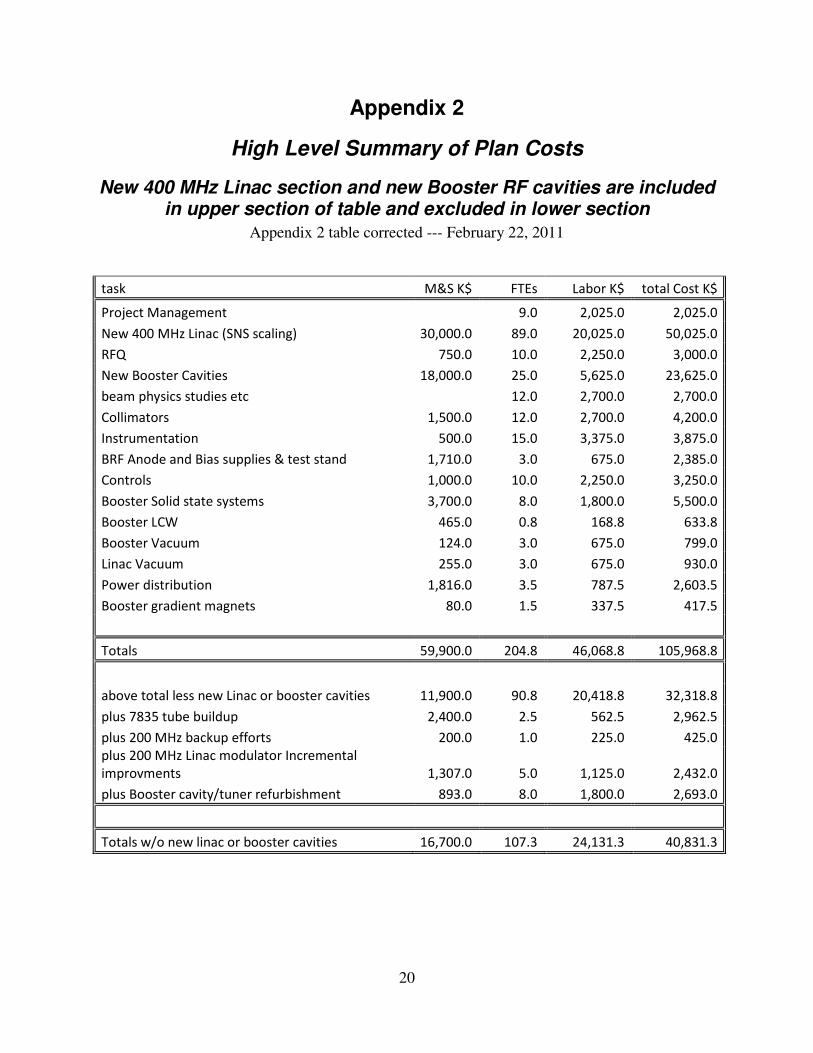
The total estimated cost to cover all these initiatives comes to $106M, including $59.9M M&S and $46M fully burdened labor. These totals, in un-escalated FY11 dollars without contingency, are shown in somewhat greater detail in the upper half of the table in Appendix 2.
Hard Limits and Incumbent Risks In his call for a Proton Source Improvement Plan, the Associate Director for Accelerators alluded to unspecified “hard limits” “beyond which proceeding becomes very costly.” That allusion, along with guidance of an $8M M&S budget for each of two years to implement an improvement plan, suggested that individual plan elements costing tens of millions of dollars would be exceedingly difficult, if not impossible, to support.
In that context, two major initiatives are, with great reluctance, dropped from the above list – replacement of the 200 MHz Linac and new Booster RF cavities.
The 200 MHz Linac replacement project is estimated as a five or six year project costing ~$50M and the Booster cavity project is estimated as a ~$23.6M, five year project. These costs include M&S and fully burdened labor in un-escalated 2011 dollars without contingency.
The risk of retaining the 200 MHz Linac is that critical power tubes become no longer available to support operations through 2025 forcing a decision, well into the 15-year run, whether to initiate a multi-year, multi-million dollar recovery plan or to declare a premature termination of operations. The 200 MHz RF power issues have been documented numerous times during the past decade [5] [6] [7]. The plan described herein does not drop the 200 MHz issue, but includes three critical, if less than fully satisfactory, elements intended to mitigate the risk. Those elements are: 1) develop a statistical tube procurement model and build up the present stock of critical tubes, 2) actively pursue development of a new 200 MHz RF power system not reliant on obsolete tubes either by collaboration with efforts at Los Alamos to that end or by investigating
6
development of a 200 MHz klystron, 3) develop a detailed conceptual design for a 400 MHz replacement of the 200 MHz Linac to reduce turn-around time should that replacement later be deemed necessary.
The price of retaining the existing Booster RF cavities is that each, now highly radioactive, cavity must be removed from the Booster ring for extensive maintenance and overhaul before 12 Hz operation can be supported and that monitoring beam losses in the small-aperture cavities will remain a continuing operational issue. The plan described herein includes elements for the cavity overhaul activities as well as alignment and beam dynamics studies to potentially mitigate the beam loss concerns.
The total estimated cost of this reduced plan is $40.8M, including $16.7M M&S and $24.1M fully burdened labor. This is shown in the lower half of the table in Appendix 2 as the cost of the full plan less the new 200 MHz Linac, less new Booster RF cavities, plus items required in lieu of new Linac and new Booster cavities.
Absent from this consideration is the 15-year operational cost of 200 MHz RF power tubes, which is of order $10M in FY11 dollars (13 years times 5 tubes per year times $150K each).
Strategy The strategy, within the scope and constraints already described, is to focus on plan elements that will achieve significant objectives within each of the three major categories:
• Maintaining viable and reliable operation of the Linac and Booster through 2025
• Increasing the Booster RF pulse repetition rate
• Doubling the proton flux
Objectives include:
• Replacement of the Cockcroft-Walton Pre-Accelerators by an RFQ system.
• Active efforts to delay or ease the potential demise of the 200 MHz RF power systems.
• Completion of the Booster RF power system solid state driver upgrade program.
• Overhaul of all Booster RF cavities and tuners.
• Completion of the spare Booster gradient magnet inventory overhaul.
• Improved beam collimation implementations in Linac, 400 MeV line, and Booster.
• Replacement of major electrical power distribution, water system, and vacuum system infrastructure components.
• Improved understanding of the machine optics, alignment, apertures and beam behavior throughout the Proton Source accelerator chain.
• Implementation of improved beam diagnostics with data acquisition and analysis software to support better machine understanding.
• A formal procedure and scheduling mechanism for focused and dedicated machine studies.
A ‘front-loaded plan’ is necessary to meet the schedule objectives put forth in the charge, to offer a sufficiently long payback on investment in the framework of service through 2025, and to limit interference with Fermilab’s Project X efforts. The strategy must be to address the Proton Source Task Force Report items of greatest concern in an aggressive manner and to address issues related to proton flux with a multi-frontal attack.

7
The plan is formed on the assumptions of a year-long accelerator shutdown, scheduled for March 2012 through March 2013, and of the availability of $8 million M&S funding in each of the fiscal years 2012 and 2013.
Advantage must be taken of the year-long shutdown, scheduled for March 2012 through March 2013, to:
• address Booster RF issues that now limit the beam pulse rate to only one-half the 12 Hz rate called for in 2013
• install the RFQ replacement for the Cockcroft-Walton Pre-accelerator
• address any near-term major utility improvements
Efforts to these ends must either commence immediately or be given greater support if the necessary preparations are to be completed in time for this shutdown.
The Plan – by Category and Element
Addressing Viable Operation at Present Levels Through 2025
Linac
200 MHz RF Power Systems
It is a strategic decision how to face the high vulnerability of the Linac 200 MHz RF power systems. There is a single supplier of the 5 MW final power amplifier tube, the Burle 7835. Fermilab, Brookhaven, and Los Alamos are the only customers for this tube. While Burle continues to supply new and rebuilt 7835s, the 200 MHz systems can be operated indefinitely subject to funding consistent with Burle’s pricing. The risk is that this sole supplier decides to stop making new and/or stop rebuilding used 7835s. If Burle would stop making new tubes today, but continue current support for rebuilding, a maximum of approximately ten years of Linac operation is forecast. If both new and rebuilt tubes become unavailable, there is today a quantity of tubes on hand to provide approximately only two years of Linac operation.
The 200 MHz RF modulators each require three F1123 high voltage switching tubes. The last manufacturer of new F1123 tubes ceased production nearly ten years ago, although two companies currently rebuild the used tubes. There are today tubes on hand to provide between five and ten years of Linac operation. If tube rebuilding remains a viable option and depending on the drop-out rate of tubes during the rebuild process, somewhere between ten to twenty years of operation is possible.
A sound strategy to assure long-term operation would replace the existing 200 MHz section of the Linac with an “SNS-like” 400MHz Linac. This would eliminate the entire 200 MHz RF power vulnerability as well as vulnerabilities of the 40-year-old 200 MHz Alvarez accelerating structures.
Given a rough cost estimate of $50M, an optimistic time frame of five years for the project, and the need for a complete physics program shutdown of roughly one year for installation, this

8
option is relegated into the “beyond the ‘hard limit’” category suggested by the Associate Director for Accelerators.
In this case, the 200 MHz RF power system plan becomes:
1. Procure new and rebuilt tubes (7835 and F1123) at a rate consistent with our ability to test these tubes at a technically limited rate in Linac Station 7. The objective is to maintain a steady stream of rebuilt F1123’s and to build up to a four-year operating supply of tested 7835’s. This provides a greater time buffer for implementation of a backup plan when that becomes necessary.
2. Define and execute incremental tasks to improve the reliability, diagnostics, and reparability of the present 200 MHz modulators and 7835 filament power systems.
3. Develop backup Plan B: to follow and collaborate with efforts at Los Alamos National Laboratory to replace their 200 MHz RF power systems with new power components at the same frequency and to investigate possible development of a klystron-based 200 MHz RF power system.
4. Develop backup Plan C: to design a “SNS-like” 400 MHz Linac compatible with the present high energy section of the Fermilab Linac.
Specific initial tasks are to:
1. Develop a 7835 tube procurement schedule strategy based on a simulation model 2. Develop a MOU with LANL for participation in and support of their efforts to develop a
viable 200 MHz RF power system replacement 3. Invest sufficient resources to develop a detailed concept for a 400 MHz accelerator to
replace the 200 MHz accelerator 4. Continue aggressively testing of incoming and existing untested power tube stock 5. Annually review the tube situation to re-assess risk to continued operations
The scale of the 200 MHz RF Power Systems element is approximately $3.9M M&S and $1.9M burdened labor.
800 MHz High Energy Linac
The Proton Task Force Report identified no critical concerns regarding the 800 MHz High Energy Linac. Normal maintenance is assumed.
PreAccelerator
A program is already underway to replace the Cockcroft-Walton Preaccelerators with a 200 MHz RFQ with the goal of eliminating operational vulnerabilities. The plan is to proceed with this program with the goal of installation during the 2012 shutdown. It is noted that this element is not necessarily independent of the 200 MHz RF power issue. Should there later be a decision to replace the 200 MHz Linac with a 400 MHz Linac, beam dynamics and space charge effects might indicate that this 200 MHz RFQ would also need to be replaced. The scale of the RFQ program is approximately $0.75M M&S and $2.25M burdened labor.
Linac Vacuum Systems
The Linac vacuum system, especially in the 200 MHz section, is composed of mostly 40 year-old equipment beyond its practical service life. The plan is to replace pumping, monitoring, and

9
controls components with present day technologies for long term reliability and maintainability. The equipment should be specified during FY11, procured in FY12, and installed during the 2012 accelerator shutdown. The scale of this plan element is approximately $255K M&S and $675K burdened labor.
Linac Controls
The plan includes budget for Linac controls system improvements to replace equipment and software that is anticipated to become un-maintainable by 2025 while improving support for operations at increased proton flux and increased average pulse repetition rates.
The scale of this plan element is approximately $0.5M M&S and $1.125M burdened labor. The budget for this element is planned for FY13.
400 MeV Transport Line
Momentum Line Beam Absorber
The only item of concern in the 400 MeV Line relevant to long term operation is a vacuum problem with the momentum line beam absorber. The plan is to complete and implement a plan that will offer a permanent solution and include appropriate beam and mechanical/vacuum instrumentation. The design is to be finalized in FY11 with procurements in FY12 to be prepared for the 2012 shutdown.
Booster
Booster Gradient Magnets
Efforts are already underway to improve that status of spare gradient magnets. The plan is to complete this spare magnet program with the goal of certifying a minimum of one, preferably two, of each of the four mechanical variations. The scale of this plan element is approximately $80K M&S and $332K burdened labor. It will be completed before the end of FY12. The magnet situation is clearly subject to re-evaluation should failures begin to occur.
Booster RF Solid State Program
The plan includes completion of the long-desired Booster RF Solid State Amplifier program. This program replaces the failure-prone cascode and distributed amplifier sections of the Booster RF Power Amplifier with solid state amplifiers located outside the beam enclosure. It also includes new modulators for all stations. Two RF stations are already configured with this equipment and have operated successfully for several years. Initial efforts to upgrade remaining stations have proceeded with little success, due to limited funding and manpower priority. The plan is to fully support and complete this program by March 2013. It is noted that this plan element is not independent of the 95 LCW water system element included in the Utilities section below.
The scale of this plan element is approximately $3.7M M&S and $1.8M burdened labor.
Other Booster RF
Other Booster RF concerns are covered in the “Booster RF Pulse Rates >7 Hz” section.

10
Booster Beam Collimation
At the present proton flux, prompt radiation levels outside the Booster tunnel in the vicinity of the collimators are unacceptably high. Component irradiation rates and residual activation levels in the tunnel near the collimators are unsustainably high. The plan is to reassess the design, implementation, and operational use of the Booster collimator system in light of present-day Booster operations to develop a specific collimator improvement plan. (More of this in the “Booster Beam Collimation” element in the “Doubling the 8 GeV Beam Flux” section) The final scale of this plan element will be known only after completion of beam studies and simulations, but $3.2M including M&S and burdened labor is allocated in the initial budget.
Booster Vacuum Systems
The Booster vacuum system is composed of mostly 40 year-old equipment beyond its practical service life. The plan is to replace pumping, monitoring, and controls components with present day technologies for long term reliability and maintainability. The equipment should be specified during FY11, procured in FY12, and installed during the 2012 accelerator shutdown. The scale of this plan element is approximately $125K M&S and $675K burdened labor.
Booster Controls
The plan includes budget for Booster controls system improvements to replace equipment and software that is anticipated to become un-maintainable by 2025 while improving support for operations at increased proton flux and increased average pulse repetition rates.
The scale of this plan element is approximately $0.5M M&S and $1.125M burdened labor. The budget for this element is planned for FY13.
Utilities
Linac and Booster Power Distribution Equipment
The plan is to address the majority of power distribution system items listed in the Proton Task Force Report as well as those additional items identified by the AD EE Support Department in Beams-doc-3741. Budget is allocated for replacing three Linac house power transformers and two Booster house power transformers including associated power panels, and motor control centers in both Linac and Booster. These include house power transformers, line-side and load-side breaker panels, and motor control center equipment for both Linac and Booster. This work is planned to be completed in FY13. The scale of this plan element is approximately $2.55M M&S and $0.79M burdened labor. The plan is to provide approximately 33% of the estimated budget in FY2012 and the remainder in FY2013.
Booster Power Distribution Duct
A duct bank carrying Booster 13.8 KV feeder cables is known to be collapsed somewhere between the Master Sub Station and the Booster. The strategy is to defer consideration of this problem until whatever time it should become unavoidable.

11
95 LCW System
95 LCW improvements are identified in the Proton Task Force Report and are necessary to support the Booster RF solid state upgrade program. This plan element includes new return water circuit booster pumps, separation of tunnel and gallery return water piping, and improvements to heat exchangers HE1 and HE2 in CUB. This element must be completed during the 2012 accelerator shutdown, in time to support Booster RF solid state upgrade operations. The scale of this plan element is approximately $465K M&S and $169K burdened labor.
Booster Sumps
The plan includes completing Booster sump system repairs and improvements identified in the Proton Source Task Force Report. This will be finished by the end of the 2012 accelerator shutdown at the cost of $50K.
Other Utilities
FESS has provided a list including additional items deemed necessary for continued operation of the Linac and Booster through 2025. This list will be reviewed to determine which items shall be included in the Proton Source Improvement Plan, which should be addressed outside the plan, and which will remain at large. Note: many items in the FESS list are included under the above paragraphs of this section.
Addressing Booster RF Pulse Rates >7 Hz
Booster
Booster RF Cavities
The strategy is to retain the existing Booster cavities as opposed to designing, building, and installing all new cavities. Minor overhaul and cooling improvements are required by each cavity structure to support 12 Hz pulse repetition rates. Major overhaul and cooling improvements are required by all cavity tuners (separate plan element below). Every cavity must be removed from the Booster ring for inspection, cleaning, tuner replacement or refurbishment, and testing. This effort requires work on radioactive items that must be performed with radiation safety technician oversight and will result in radiation doses to workers.
See Appendix 3 for specific initial task pertinent to this plan element.
The scale of this plan element remains to be separated from the scale of the cavity tuner element below.
Booster RF Cavity Tuners
The plan is to establish a ‘Booster tuner factory’ that will have, within one year, the capacity and manpower to produce new or refurbished tuners at the rate of three tuners per two weeks with functional water cooling on the inner cones to support full 15 Hz operation. It is recognized that this implies work on radioactive items that must be done with radiation safety technician oversight and will result in radiation doses to workers. Tuner work must be completed for all cavities before the 12 Hz or higher beam rate is possible. Subject to significant change as the

12
actual plan for dealing with the tuner cooling and maintenance issues is developed, the initial budget allocation for this element is $893K M&S and $1.65M burdened labor.
Booster RF Anode Supplies
The plan includes replacing the Booster RF Anode Supply transformers and vacuum circuit breakers and refurbishing the DC cabinet components as outlined in the Proton Source Task Force Report.
See Appendix 3 for specific initial task pertinent to this plan element.
The scale of this plan element is approximately $860K M&S and $225K burdened labor. The budget for this element is planned in the second half of FY13.
Booster RF Bias Supplies
The plan is to test the ability of the West Gallery RF bias power supply transformers to operate at 15 Hz; the West Gallery supplies have transformers of lower rating than East Gallery supplies.
See Appendix 3 for specific initial task pertinent to this plan element.
On the assumption that the transformers need to be replaced, the allocated budget for this element is $350K M&S and $225K burdened labor. The budget for this element is planned at the beginning of FY13. The work can be completed station-by-station immediately following the 2012 shutdown with minimal impact to HEP operations.
Spare Booster RF Cavity
Completing assembly of one spare Booster cavity, as outlined in the Proton Source Task Force Report, is a high priority task. The plan calls for assigning manpower to complete this spare cavity at the earliest possible schedule, before the end of July 2011 at an approximate total cost of $153K, M&S and burdened labor.
Utilities
No utilities issues are specific to Booster RF pulse rates >7Hz.
Addressing Doubling the 8 GeV Beam Flux
There are a number of steps which will result in improvement of Booster performance. The most effective and, consequently, having the highest priority are the first four listed elements in the Booster section below.
Linac
Emittance Reduction/Control
The new RFQ Front-End offers the possibility of reduced beam loss in Linac with subsequent reduction of transverse beam emittance delivered to the Booster. The expected emittance reduction is about 25%, which should result in some reduction of beam loss in the Linac and Booster. The factor of two loss improvements in Booster looks extremely ambitious. Presently, it is difficult (close to impossible) to make reliable prediction of this loss improvement.
13
Linac Creation of Booster Extraction Kicker Notch
The plan includes investigation of creating a Booster extraction kicker notch in the beam at the front end of the Linac (see Booster notch item).
Linac Beam Instrumentation and Diagnostics
The plan includes budget for Linac beam instrumentation and diagnostics improvements to facilitate achievement and enable support of operations at increased proton flux.
The scale of this plan element is approximately $0.25M M&S and $1.125M burdened labor. The budget for this element is planned for FY13.
Linac Beam Collimation
The plan includes an investigation to what extent collimation in the Linac might improve the beam loss situation in Linac, 400 MeV line, and Booster.
400 MeV
Optics match between Linac and Booster
Better match between Linac and Booster might result in a decrease of beam emittance in the Booster and reduction of beam loss. This work does not require an installation of new hardware or software. Follow-up of earlier efforts is estimated at about 1 man-month. With appropriate priority, the total duration should be less than 3 months.
Beam Diagnostics and Controls
The plan includes developing specifications for improved beam diagnostics if needed and control algorithms to stabilize beam steering.
400 MeV Beam Collimation
The plan includes investigation of how much a beam collimation in the 400 MeV line might reduce the radiation in 400 MeV line and Booster. Presently, it is estimated that improvements of beam collimation in the Booster should address the problem. Therefore, this 400 MeV work should be done after assessment of Booster collimators efficiency (see Booster collimation element below). About 0.5 man-months is required to estimate a necessity of 400 MeV line beam collimation.
Booster
Booster Beam Collimation
The plan is to reduce radiation problems associated with the present Booster collimation system by reassessing its design, implementation, and operational use in light of present-day Booster operations. This might result in a proposal for a new Booster collimation system.
Collimators do a satisfactory work on a reduction of radiation in the most of Booster tunnel. However radiation is already unacceptably high in the vicinity of collimators and its further increase does not look as a possible solution. The radiation significantly exceeds the level predicted by simulations performed during the design phase of the Booster collimators. The following steps are necessary to address the problem.

14
1. Perform realistic simulations of the beam loss and radiation levels and compare them with observations in an effort to learn why present radiation exceeds the expected levels. It is difficult to estimate the effort required to determine why the observed radiation significantly exceeds the old simulations. Current estimates are between 2 and 6 months for total work duration (1-3 men-months of actual work.) This work was started in January 2011.
2. Depending on the outcome of the previous step, we expect 2 possible scenarios. First, better machine tuning together with improvements of cogging (see below) will be sufficient to address the problem. Second, a new collimation system or an upgrade of the existing one needs to be elaborated, designed and build. The first outcome looks somewhat less probable. It is impossible to put a realistic effort estimate in the case of the second outcome. It is expected to be clarified by June 2011. The worst case scenario can require few years to fully address the problem.
As described, the final scale of this plan element will be known only after completion of beam studies and simulations, but $3.2M including M&S and burdened labor is allocated in the initial budget.
Booster Extraction Notch Cogging Improvement
Presently, cogging in the Booster is performed by control of beam radial position via adjustments of the RF frequency. This solves the problem of synchronized beam transfers to the MI, but brings other problems. In particular, it complicates setup of beam collimators as discussed above. A new cogging scheme needs to be implemented based on magnetic field feedback and control in place of the RF cogging method now used. This scheme would use all the Booster short straight section horizontal correctors to modify the time-dependent bending field of the ring. The objective is to enable ± 42 bucket cogging with fixed horizontal orbit in Booster. This opens the possibility of pre-notching in the front end of the Linac as a means of reducing the radiation load now suffered by notching at 400-700 MeV in the Booster. A more effective Booster collimation scheme that need not cope with the radial orbit variations inherent in the RF cogging implementation becomes feasible. Improved orbit stability enables better control of optics, tunes, and chromaticities throughout the entire accelerating cycle with subsequent reduction of beam loss.
The work on the new cogging scheme is already started in January 2011. Operation of new cogging scheme could be expected at the beginning of 2012; most of the hardware is already installed. The plan budget allocates a total of $710K for this element.
Booster Extraction Kicker Notch Creation
Presently, in the case of beam transfers to MI the extraction notch in the beam is created by fast kickers at the energy of ~700 MeV. The new cogging scheme (see above) has to be designed and built so that the notching might be done at the injection energy (400 MeV), which should reduce the radiation related to the beam notching by about two times. An additional about factor-of-two reduction can be achieved by pre-notching of the linac beam at the Booster revolution frequency. The rms momentum spread of linac beam is about 8e-4; this will result in a smear of the notch edge of about 1.5 bucket before the beam is bunched. Nevertheless, appropriate pre-notching in linac should result in additional reduction of beam loss by about factor of two.

15
The following steps are required.
1. Perform a simulation of Booster bunching with beam pre-notching in the linac. Simulations have to take into account the beam space charge. They have to point out the optimal length of the pre-notch and an expected reduction of the beam loss.
2. Install the pre-notch kicker in the vicinity of the new linac RFQ.
Booster Orbit and Alignment
The indirect evidence pointed out by imperfections of Booster alignment, beam steering, optics mismatch, and beam displacements due to cogging suggests that the Booster acceptance is about half of its theoretical limit with orbit imperfections making the major contribution. The plan is to achieve Booster acceptance much closer to its “theoretical” maximum of 40 mm mrad (normalized). The following steps are required to address the problem:
1. Using patterns of corrector strengths and beam loss determine the places making largest contributions to the beam orbit imperfections and formulate priorities for Booster realignment.
2. Realign the Booster during one or, if required, more shutdowns. 3. After the new cogging system is implemented perform careful work on Booster orbit
with objective of maximizing the Booster acceptance.
Booster Beam Instrumentation and Diagnostics
The plan includes budget for Linac beam instrumentation and diagnostics improvements to facilitate achievement and enable support of operations at increased proton flux.
In particular, the present setup of Booster Beam Position Monitor electronics does not allow reliable acquisition of the turn-by-turn data required for optics measurements. It will be determined if it is possible to achieve a satisfactory accuracy of turn-by-turn measurements with present BPM system or its upgrade. If not, a new BPM electronics system will be designed and build. About 2 months are needed to analyze the status and problems of the present BPM electronics. It will take about 1.5 year to design and build new electronics if required.
The scale of the total Booster Instrumentation plan element is approximately $0.25M M&S and $1.125M burdened labor. The budget for this element is planned for FY13.
Beam Optics
Although the Booster is the oldest circular machine in the Fermilab complex, its optics has not been measured to the same accuracy as for other rings. The installation of new cogging scheme and improvements of BPM electronics will allow accurate optics measurements to be performed and should result in the same optics reliability as for other machines. In addition to the reduction of beam loss, good control of the machine optics should make Booster operation more reliable. The plan is to reduce emittance growth and improve beam transmission by better matching between Linac and Booster, improving Booster optics, and reducing x-y coupling.
Injection Painting
If the Linac beam emittance is sufficiently reduced as a result of the new RFQ Front-End, the plan is to pursue emittance control in the Booster using an injection painting scheme.

16
Transverse Feedback
Introduction of transverse feedback into Booster operation should allow Booster operation with reduced chromaticity thus resulting in a reduction of beam loss. The first tests of the system were already carried out in 2010. Expected effort to make it operational is 3-to-6 man-months. M&S money can be required if the studies will show a necessity of more powerful power amplifiers.
Radiation shielding
The plan will include implementation of improved radiation shielding as might be necessary to meet FESHM and FRCM requirements at the doubled proton flux. Initiatives will also be taken to reduce component irradiation rates and residual activation levels in areas where maintenance workers must work with improved shielding at selected locations.
Utilities
No utilities issues are specific to doubling the proton flux.
Cost and Schedule Summary The total estimated cost of the plan is $41M (un-escalated FY11 dollars, no contingency) from now through FY13. This includes $16.7M for materials and services and $24M for fully burdened labor.
A Microsoft Project plan has been established that captures the M&S and labor cost allocations. The time profile of M&S expenditures is consistent with the present budget guidance, $0.7M in FY11 and $8.0M in each of FY12 and FY13. M&S costs are taken from the Proton Source Task Force Report where available and engineering estimates otherwise.
Top-down labor estimates are included in the plan, distributed among the plan elements, and with cursory assignment of correct OHAP labor categories. No effort has yet been applied to labor scheduling or resource leveling. The labor represents approximately 107 FTEs over a span of less than three years, most of which must come from outside the present Proton Source Department staff.
Top level contents of the MS Project plan are shown in Appendix 4.
The plan assumes that approximately flat operational budgets for the Proton Source machines remain available in parallel with this plan and beyond; the exception is that the budget portions for RF power tubes must grow as necessary to cover actual yearly tube replacement costs.
The plan is exceedingly ambitious to effectively invest the M&S budget on a short time scale and to accomplish the necessary preparation for and work during the 2012-13 shutdown.
The Next Steps The Proton Source Improvement Plan is of sufficient importance that it deserves Directorate Program Management Group status with meetings, regularly scheduled and held, to discuss progress and impediments. Assignment of a full-time program scientific/technical manager with

17
adequate project management support to oversee and steer the program is necessary for the plan to develop further. Second-level managers, with this work as their highest priority, must be assigned for the plan to mature and those managers must be given control of adequate technical resources for execution to gain momentum. Now is not too early to begin.
Due to their lead times and mission criticality, the elements requiring immediate attention and assignment of full-time management and scientific/technical personnel are:
• Linac RFQ project. This program is now effectively underway, but the project might benefit from a constructive advice from a wider group with a range of relevant experiences. Both a conceptual design review by independent experts and an internal technical design and implementation plan review are appropriate at this stage.
• Booster RF Solid State Program. This and the other Booster RF efforts are presently guided by one individual able to devote an inadequate fraction of his time to each. Undivided attention is required to be prepared for the 2012 shutdown.
• Booster RF Cavities, Tuners, Anode Supplies, and Bias Supplies. Each of these elements cries for immediate, undivided attention for there to be any chance of supporting 12 Hz operation in 2013.
• The entire “Doubling the 8 GeV Beam Flux” category. This range of elements requires one dedicated and informed scientific staff person to serve as a focal point. That person shall provide the oversight and guide the planning of investigations and beam studies necessary to achieve sufficient understanding of the issues. The time scale should be such as to enable proper preparation for effective use of the 2012 shutdown.
• 200 MHz Linac RF Power Systems backup Plans B and C. Especially Plan C to design a “SNS-like” 400 MHz Linac compatible with the present high energy section of the Fermilab Linac should be addressed.
• Linac and Booster Power Distribution Equipment. Items within this category that will be replaced must be prioritized and pre-procurement activities such as specification development and installation planning need to begin in order to effectively procure the equipment in a timely manner when funds become available.
• Booster Spare RF Cavity Program. This effort is in immediate need of skilled mechanical technician labor.
References [1] Proton Source Task Force Report, Beams-doc-3660, http://beamdocs.fnal.gov/AD-public/DocDB/ShowDocument?docid=3660
[2] Proton Source December 2010 Workshop, http://beamdocs.fnal.gov/AD-public/DocDB/DisplayMeeting?conferenceid=114
[3] Proton Plan, 11/09/04, http://www-accel-proj.fnal.gov/internal/Proton_Plan/LinacPA_TF/Proton_Plan_v2.pdf
[4] Proton Plan Web Page, http://www-accel-proj.fnal.gov/internal/Proton_Plan/index.shtml
[5] Status of the Low-Energy Linac 200-MHz RF Stations, January 31, 2002, http://lss.fnal.gov/archive/test-tm/2000/fermilab-tm-2166.pdf

18
[6] Fermilab Linac Status and Outlook Briefing to the Directorate, August 9, 2002, http://beamdocs.fnal.gov/AD-public/DocDB/ShowDocument?docid=3549
[7] Final Report of the 7835 Task Force, August 16, 2005, http://www-accel-proj.fnal.gov/internal/Proton_Plan/LinacPA_TF/final_report/Final_Report_with_appendices_embedded.pdf

19
Appendix 1
Charges for the Proton Source Improvement Plan
From Stuart Henderson, Associate Director for Accelerators (Proton Source Workshop, Beams-doc-3739-v1, 12/7/2010)
• The Proton Improvement Plan, when executed, should enable Linac/Booster operation
capable of
� delivering 1.8E17 protons/hour (at 12 Hz) by May 1, 2013
� delivering 2.25E17 protons/hour (at 15 Hz) by January 1, 2016
while
� maintaining Linac/Booster availability > 85%
� and maintaining residual activation at acceptable levels
and ensuring a useful operating life of the proton source through 2025.
From Roger Dixon, Accelerator Head (email 11/3/2010)
I would like you to prepare a plan based on the Proton Task Force report for the
improvement and upgrade of the Proton Source. The plan should define a program that will be
carried out to improve the reliability and performance of the Pre-Acc, Linac, and Booster. It
should outline a schedule for carrying out the work and cost and manpower estimates for each
task outlined in the plan. In order to make a feasible plan it will be necessary to take the
Laboratory’s physics program into account, and a plan should be made to accommodate as
much of the proposed program as possible. This simply means that you should optimize the plan
to achieve maximum reasonable output and reliability. All items in the task force report should
be considered in making the plan, however, you may conclude that some of the items are not
feasible to complete without major interruption to the Laboratory’s physics program. In such
cases, the reason for not including the item in the plan should be stated in the plan.
20
Appendix 2
High Level Summary of Plan Costs
New 400 MHz Linac section and new Booster RF cavities are included in upper section of table and excluded in lower section
Appendix 2 table corrected --- February 22, 2011
task M&S K$ FTEs Labor K$ total Cost K$
Project Management
9.0 2,025.0 2,025.0
New 400 MHz Linac (SNS scaling) 30,000.0 89.0 20,025.0 50,025.0
RFQ 750.0 10.0 2,250.0 3,000.0
New Booster Cavities 18,000.0 25.0 5,625.0 23,625.0
beam physics studies etc
12.0 2,700.0 2,700.0
Collimators 1,500.0 12.0 2,700.0 4,200.0
Instrumentation 500.0 15.0 3,375.0 3,875.0
BRF Anode and Bias supplies & test stand 1,710.0 3.0 675.0 2,385.0
Controls 1,000.0 10.0 2,250.0 3,250.0
Booster Solid state systems 3,700.0 8.0 1,800.0 5,500.0
Booster LCW 465.0 0.8 168.8 633.8
Booster Vacuum 124.0 3.0 675.0 799.0
Linac Vacuum 255.0 3.0 675.0 930.0
Power distribution 1,816.0 3.5 787.5 2,603.5
Booster gradient magnets 80.0 1.5 337.5 417.5
Totals 59,900.0 204.8 46,068.8 105,968.8
above total less new Linac or booster cavities 11,900.0 90.8 20,418.8 32,318.8
plus 7835 tube buildup 2,400.0 2.5 562.5 2,962.5
plus 200 MHz backup efforts 200.0 1.0 225.0 425.0
plus 200 MHz Linac modulator Incremental
improvments 1,307.0 5.0 1,125.0 2,432.0
plus Booster cavity/tuner refurbishment 893.0 8.0 1,800.0 2,693.0
Totals w/o new linac or booster cavities 16,700.0 107.3 24,131.3 40,831.3

21
Appendix 3
Plan for Booster HL RF System to operate at 15Hz by 2013 J. Reid - January 7, 2010
1. Complete the solid state driver upgrade project. a. New series tube modulators b. 4 kW solid state driver amplifiers c. New 150 kW power amplifiers d. Installation, including installing all new cables between tunnel and gallery. e. Provide detailed schedule for fabrication time, costs, manpower, and installation.
2. Develop detailed schedule, remaining costs, and manpower requirements to complete the solid state driver upgrade program.
3. Test large bore Booster Cavity in MI-60 test station.
a. Run cavity at 15 Hz full gradient and measure select thermal heating.
b. If cavity passes all proposed tests, schedule to install cavity in place of a small bore cavity presently running in Booster.
c. This frees up a standard Booster cavity that can be shipped to MI-60 test station.
4. Install standard Booster cavity in MI-60 test station so measurement can be made on 15 Hz performance.
a. Install diagnostic devices to measure thermal heating of key components.
b. Measure temperature rise of tuners and other key components (including mode dampers) with normal cooling on center conductor and no ferrite tuner cone cooling. This will answer the question “do we need cone cooling lines connected?”
c. Run cavity at nominal operating voltage for first set of measurements.
d. Run cavity at 15Hz nominal operating voltage 24-7 for at least one month.
e. Pending results from c, run cavity at 10 % higher gradient and record all thermal profiles.
f. Connect ferrite tuner cone cooling and repeat all of the above measurements.
g. The above tests will determine the viability of the cavity and tuner assemblies to run at 15Hz.
h. Develop plan for refurbishing cavities and tuners.
5. Order additional spare components (ceramic & copper spinnings) to make ~ 15 spare HV blocking capacitors.
6. A purchase order (597838) has been placed for 10 – 15 additional ceramic windows for cavity.

22
7. Starting in January of 2011 going to build a Booster production style spare small bore rf cavity using selected parts salvaged from the original welded prototype cavity.
8. Build at least 3 additional tuners in addition to the present spares.
9. Need 2 mechanical technician for cavity work defined in steps 7 and 8 above.
10. Update HV chokes.
11. Increase mode damper power dissipation (load).
12. West gallery bias supply transformer heating
a. Push to complete the spare Ferrite Bias supply for Booster which is presently under construction at MI-60. Two other Ferrite Bias supplies are under construction for the NOvA upgrade of MI.
b. Once spare supply is complete, install in one of the West gallery stations. This allows shipping the standard Ferrite Bias supply (MK I) from WG to MI-60 for thermal testing at 15 Hz.
c. Upgrade Ferrite Bias supply SCR rectifier packages to replace old PVC heat sinks which leak if LCW pressure surges occur (West gallery supplies only).
13. Measure operating temperatures of the high power AC distribution system. Main concern is the 480 distribution cables and disconnects to the Ferrite Bias supplies (both East and West Galleries).
14. Anode Power Supply Items
a. Replace East and West Anode Supply main rectifier transformers with one’s like recently purchased units for MI.
b. Replace the 13.8kV step start VCB’s for the above transformers. The VCB’s would be identical to those bought for MIRF and manufactured by Ross Engineering.
c. Update select internal components and install new controls.

23
Appendix 4
Microsoft Project File Outputs
Proton Source Improvement Plan M&S Cost Profile by Calendar Quarter
Fixed Cost
Year Calendar
Quarter PROTON SOURCE
IMPROVEMENT PLAN M&S Grand
Total
2011 Q1 700,000 700,000
Q2 0 0
Q3 0 0
Q4 6,200,000 6,200,000
2011 Total 6,900,000 6,900,000
2012 Q1 1,200,000 1,200,000
Q2 600,000 600,000
Q3 0 0
Q4 4,574,000 4,574,000
2012 Total 6,374,000 6,374,000
2013 Q1 3,426,000 3,426,000
Q2 0 0
Q3 0 0
Q4 0 0
2013 Total 3,426,000 3,426,000
Grand
Total 16,700,000 16,700,000

24
Microsoft Project File Gantt Chart

25
Appendix 5
Proton Expectations by Experiments Compiled by Bob Webber, November 24, 2010
NOvA Table 2.1 from NOvA Technical Design Report dated October 8, 2007
http://www-nova.fnal.gov/nova_cd2_review/tdr_oct_23/chapter_2_numi_for_nova.pdf
NOvA request/expectation is 6.0E20 protons per year @ 120 GeV for 6 years (36E20 total)
per 15kT of detector mass.
Wants 700kW of beam at possibly various energies, nominally 120 GeV. For 4615 hours per year (6E20 per year/1.3E17 per hr) equals 27 weeks/year
Want 1.3E17 pph.

26
Micro-BooNE Page 29 from MicroBooNE Proposal dated October 15, 2007 available at:
http://www-microboone.fnal.gov/Documents/MicroBooNE_10152007.pdf
Micro-BooNE request/expectation is 6E20 total protons on target over 2-3 years.

27
Mu2e Table 2.1 from Mu2e Proposal dated October 10, 2008 available at:
http://mu2e-docdb.fnal.gov/cgi-bin/ShowDocument?docid=388
3.15E7 sec/year @365/24/7 so 2E7 sec/yr request is 33 weeks per year.
Want 6.48E16 pph.
Mu2e request/expectation is 3.6E20 protons on target per year for 2 years.

28
G-2 Proposal Pages 41 and 42 of Proposal dated February 9, 2009 and available at:
http://www.fnal.gov/directorate/program_planning/Mar2009PACPublic/Proposal_g-2-3.0Feb2009.pdf
They assume six Booster batches at 4E12 per 1.33 sec MI cycle = 1.8E13 protons per second = 6.5E16 pph.
G-2 request/expectation is 4E20 protons on target over 1.35 years = 3E20/year.

29

![epub.ub.uni-muenchen.de · JHEP01(2014)109 [GeV] 0 m 1000 2000 3000 4000 5000 6000 [GeV] 1/2 m 800 700 600 500 400 300 q~ (2400 GeV) q~ (1600 GeV) (1000 GeV) ~ g (1400 GeV) ~ g >0](https://img.dokumen.tips/doc/110x75/5f5af63e9c508c0a904d8c92/epububuni-jhep012014109-gev-0-m-1000-2000-3000-4000-5000-6000-gev-12-m.jpg)


![1 T2K Experiment - University of Rochestermamday/shortthesis.pdffor T2K [?]. Figure 1.3: The NA61 detector. NA61 uses 30 geV protons on a graphite target like T2K to give precise predictions](https://img.dokumen.tips/doc/110x75/5f705a97147bc57aee7cc1b7/1-t2k-experiment-university-of-mamdayshortthesispdf-for-t2k-figure-13.jpg)