Embed Size (px)
Citation preview

1 2 3 4 5 6 7 8 9 10 11 12 13 14 15 16 17 18 19 20 21 22 23 24 25 26 27 28 29 30 31 32 33 34 35 36 37 38 39 40 41 42 43 44 45 46 47 48 49 50 51 52 53 54 55 56 57 58 59 60 61 62 63 64 65
A PCI planning algorithm for jointly reducing reference
signal collisions in LTE uplink and downlink
R. Acedo-Hernandez∗,a, M. Torila, S. Luna-Ramıreza, C. Ubedab
aDpt. Ingenierıa de Comunicaciones, Universidad de Malaga, Malaga, SpainbEricsson, E-28045 Madrid, Spain
Abstract
In this paper, a novel automatic planning method is proposed for allocatingPhysical Cell Identifiers (PCI) to cells in a Long Term Evolution (LTE)system based on handover and cell load measurements. The method aimsat avoiding PCI collision and confusion problems, while reducing ReferenceSignal (RS) collisions between neighbor cells. For this purpose, the problemis formulated to consider RS collisions both in DownLink (DL) and UpLink(UL). Then, a classical graph partitioning algorithm is adapted to solve thegraph coloring problem behind PCI planning. The considered algorithmis the multi-level version of the Fiduccia and Mattheyses local refinementalgorithm. Performance assessment is carried out on graphs constructedfrom data collected in live LTE network. Results show that the proposedalgorithms can avoid PCI collision and confusion problems, while reducingDL RS collisions and almost eliminating UL RS collisions compared to arandom plan.
1. Introduction
In recent years, the evolution of mobile networks has led to a signifi-cant increase in network system requirements and complexity. Therefore,network operators seek automated solutions for operation and maintenancetasks to minimize the workload and errors due to human interaction. Thisjustifies that the new Long Term Evolution (LTE) standard is known for its
∗Corresponding Author: R. Acedo-Hernandez, [email protected], +34 952136311Email addresses: [email protected] (R. Acedo-Hernandez), [email protected] (M.
Toril), [email protected] (S. Luna-Ramırez), [email protected] (C. Ubeda)
Preprint submitted to Computer Networks March 13, 2017
*ArticleClick here to view linked References

1 2 3 4 5 6 7 8 9 10 11 12 13 14 15 16 17 18 19 20 21 22 23 24 25 26 27 28 29 30 31 32 33 34 35 36 37 38 39 40 41 42 43 44 45 46 47 48 49 50 51 52 53 54 55 56 57 58 59 60 61 62 63 64 65
self-organization features, which include capabilities for self-planning, self-optimization and self-healing [1].
In LTE, Physical Cell Identifier (PCI) planning has been identified asan important use case for self-planning [2] [3]. A PCI is a low-level cellsignature used to identify cells in mobility procedures, such as handovers orcell reselection [4]. The number of possible PCI values is limited, which forcesseveral base stations to share the same PCI. As a result, a wrong assignmentof PCIs may cause that two adjacent cells use the same PCI (problem referredto as collision) or a serving cell has two neighbors with the same PCI (referredto as confusion) [1]. Both issues prevent users from detecting target cells,causing that no radio communication is possible. Therefore, proper PCIallocation is essential for an adequate service performance. Such an allocationis a non-trivial task due to the limited number of PCIs.
At the same time, PCI determines the location in time and frequencyof DownLink (DL) signaling channels, amongst which are DL Cell-specificReference Signals (CRS), and the specific set of Demodulation ReferenceSignals (DM RS) in UpLink (UL).
In DL, CRSs are transmitted in different subcarriers depending on thePCI assigned to the cell. Thus, each cell has a specific pilot pattern corres-ponding to its cell identity. The number of possible pilot patterns dependson the antenna configuration, but it is always less than 6 [5], causing thatCRSs of surrounding cells often collide. CRS collisions degrade Signal-to-Interference-plus-Noise Ratio (SINR) estimates, reported by the User Equip-ment (UE), which are used by the eNB to select the modulation and codingscheme (MCS) for DL transmission. Thus, an improper PCI planning maygive inaccurate SINR estimates, which leads to inefficient data transmissionin the DL [6].
In UL, PCI defines the set of DM RSs transmitted by users, used by thebase station for channel estimation and coherent demodulation in the Physi-cal Uplink Shared Channel (PUSCH) and Physical Uplink Control Channel(PUCCH) [5]. If two users of different cells use the same DM RS, the de-coding process in PUCCH or PUSCH is degraded, which might cause thatthe base station could not identify the user correctly. As described in [7],the definition of DM RSs in PUSCH can be decoupled from PCI planning,and, thus, DM RS design can be optimized independently to the PCI plandesign. However, this is not the case for PUCCH, where DM RSs can onlybe controled by PCI planning.
Then, the benefits of considering Reference Signals (RS) in PCI planning
2
1 2 3 4 5 6 7 8 9 10 11 12 13 14 15 16 17 18 19 20 21 22 23 24 25 26 27 28 29 30 31 32 33 34 35 36 37 38 39 40 41 42 43 44 45 46 47 48 49 50 51 52 53 54 55 56 57 58 59 60 61 62 63 64 65
are: a) in the DL, improved channel estimates, and, hence, better radio linkefficiency, leading to higher DL user throughput and larger network capacity,and b) in the UL, a reduced PUCCH failure rate, which leads to lower ULdelays due to less retransmissions and higher DL throughput due to a morerobust Channel Quality Indicator (CQI) reporting.
In the literature, most PCI planning approaches are designed to avoidcollision and confusion problems [8] [9] [10]. With these two objectives,PCI planning is usually formulated as a graph coloring problem, whichcan be solved by graph theoretic algorithms (e.g., greedy algorithm) [8] [9]or general-purpose discrete optimization algorithms (e.g., random search,simulated annealing, tabu search, genetic algorithms, constraint satisfac-tion algorithms, linear programming, ...) [11]. Preliminary studies consi-dered centralized PCI planning schemes [12] and later studies evaluate dis-tributed versions [13] [9] [14] [15]. Recent works have extended the analy-sis of PCI planning to heterogeneous LTE networks, consisting of severallayers, by considering collision and confusion between cells of different la-yers [16] [17] [18] [19] [20] [21] [22] [23] [24]. Also, recent works have ex-tended the PCI planning use case to emerging scenarios relevant to 5G, e.g.,multi-operator [25] and ultra-dense network [26] scenarios. Moreover, con-sidering UL RS collisions when assigning PCIs in 5G networks will be of theutmost importance, as UL performance is critical in machine type commu-nications for Internet-of-Things applications [27]. However, none of thesestudies consider DL CRS or UL DM-RS collisions. Only in [28], a simplePCI planning method is proposed to reduce DL CRS collisions between cellsof the same site. The method does not avoid DL CRS collisions between non-cosited adjacent cells, nor does it consider UL DM-RS collisions. Likewise,a centralized PCI planning scheme based on a genetic algorithm is proposedin [29] to avoid CRS collisions and thus improve network coverage and DLuser throughput.
To the authors' knowledge, no PCI planning method has considered ULand DL RS collision together with PCI collision-confusion problems. Asshown later, building a PCI plan for just one of these criteria leads to solu-tions with suboptimal performance in terms of the other criteria. Likewise,classical PCI planning methods often rely on heuristic graph coloring algo-rithms that must be designed from scratch with the subsequent developingeffort. Moreover, previous PCI planning approaches are based on estimatesbuilt by radio network planning tools, and do not make the most of perfor-mance statistics in the network management system.
3

1 2 3 4 5 6 7 8 9 10 11 12 13 14 15 16 17 18 19 20 21 22 23 24 25 26 27 28 29 30 31 32 33 34 35 36 37 38 39 40 41 42 43 44 45 46 47 48 49 50 51 52 53 54 55 56 57 58 59 60 61 62 63 64 65
In this work, a novel formulation of the PCI planning problem is pre-sented that considers UL and DL CRS collisions problems as well as PCIcollision-confusion problems. In the proposed approach, problem instancesare constructed from live network measurements. Unlike previous work, thegraph coloring problem in PCI planning is re-formulated as a graph parti-tioning problem, for which very effective codes exist in the public domain(e.g., METIS [30], JOSTLE [31], Chaco [32]). Then, PCI planning is solvedby a multi-level refinement graph partitioning algorithm, which is the com-mon benchmark against which other graph partitioning methods are com-pared [33] [34] [35]. Finally, the method is validated with a problem instancetaken from a real LTE network.
The rest of the paper is organized as follows. Section 2 presents the newformulation of the PCI planning problem that also considers RS collisions,which is the main contribution of this work. Section 3 presents the proposedmulti-level refinement graph partitioning algorithm. Section 4 presents theresults of the PCI planning method in a real problem instance. Finally,Section 5 presents the main conclusions of the study.
2. Problem formulation
This section begins with the basics of PCI assignment in cellular networks.Then, the proposed graph-theoretic formulation of the PCI planning problemis presented. Finally, the problem is re-formulated as a graph partitioningproblem.
2.1. PCI planning in cellular networks
The PCI is obtained by the UE from the Primary Synchronization Sig-nal (PSS) and Secondary Synchronization Signal (SSS). From SSS, the UE
obtains the physical layer cell identity group index, N(1)ID (ranging from 0
to 167). From PSS, the UE obtains the physical layer identity index, N(2)ID
(ranging from 0 to 2) [5]. Then, the PCI is defined as:
PCI(i) = 3 ·N (1)ID(i) +N
(2)ID(i), (1)
ranging from 0 to 503. The number of unique PCI values is limited to 504,so these have to be reused across the network. Such a reuse of PCIs leads todifferent problems.
4

1 2 3 4 5 6 7 8 9 10 11 12 13 14 15 16 17 18 19 20 21 22 23 24 25 26 27 28 29 30 31 32 33 34 35 36 37 38 39 40 41 42 43 44 45 46 47 48 49 50 51 52 53 54 55 56 57 58 59 60 61 62 63 64 65
A first issue happens when a UE is in the coverage area of two cellssharing the same PCI. This UE may not be able to identify its serving cell.As a result, radio channel information may not be correctly decoded. Thisproblem is referred to as a collision event. A second issue occurs when a UEis camped in a serving cell and two neighbor cells share the same PCI. Inthis case, the target cell would not be identified properly when a handoveris executed. This problem is referred to as a confusion event. A good PCIplan should avoid collision and confusion problems assigning the same PCIvalue to quite distant cells.
In addition to avoiding PCI collision and confusion, a proper PCI plancan increase DL and UL transmission efficiency by reducing RS collisions.
In DL, PCI defines the allocation of CRSs along the Physical ResourcesBlocks (PRBs) in time and frequency. PRB is the minimum unit of resourceallocation in LTE, consisting of a bandwidth of 180 kHz and a time intervalof 0.5 ms.
Fig. 1 shows the CRS pattern in time and frequency for 1 PRB and 1Transmission Time Interval (TTI), with normal cyclic prefix. Squares in thefigure represent the different Resource Elements (REs), each consisting of thecombination of a subcarrier and an OFDM symbol. Dark squares correspondto REs reserved for CRSs, while white squares correspond to REs reservedfor data transmission. In the time domain, CRSs are transmitted in the sameOrthogonal Frequency Division Multiplexing (OFDM) symbol of the framestructure in all cells, regardless of the PCI value. However, in the frequencydomain, CRSs are allocated to different subcarriers depending on the PCIvalue of the cell. The number of possible CRS allocation patterns depends onthe antenna configuration. As observed in Fig. 1(a), when using one antennaport (i.e., Single Input Single Output -SISO- or Single Input Multiple Out-puts -SIMO- schemes), 6 CRS allocation patterns are possible. The specificpattern in a cell is given by the PCI of the cell by the operation PCI mod6. In case of two or four antenna ports (i.e., Multiple Inputs Single Output-MISO- or Multiple Inputs Multiple Outputs -MIMO- schemes), shown inFig. 1(b), the CRS allocation pattern is given by the operation PCI mod 3,which coincides with the value of PSS in the cell.
When two cells have the same CRS allocation pattern, CRS collisionsdegrade DL Signal-to-Interference-plus-Noise Ratio (SINR) estimates. Thereason is that the UE assumes that interference in data channel is as high asthat experienced in REs where CRS are allocated, which is not necessarilytrue. SINR estimates are reported by the UE to the eNodeB (eNB) and used
5

1 2 3 4 5 6 7 8 9 10 11 12 13 14 15 16 17 18 19 20 21 22 23 24 25 26 27 28 29 30 31 32 33 34 35 36 37 38 39 40 41 42 43 44 45 46 47 48 49 50 51 52 53 54 55 56 57 58 59 60 61 62 63 64 65
Time
Fre
qu
en
cy
CRS Data
(a) 1 antenna port
Time
Frequency
Antenna port 0 Antenna port 1
CRS Antenna port 1 CRS Antenna port 1 Data Not used
(b) 2 antenna ports
Figure 1: Cell-specific reference signal pattern in a PRB and TTI.
6

1 2 3 4 5 6 7 8 9 10 11 12 13 14 15 16 17 18 19 20 21 22 23 24 25 26 27 28 29 30 31 32 33 34 35 36 37 38 39 40 41 42 43 44 45 46 47 48 49 50 51 52 53 54 55 56 57 58 59 60 61 62 63 64 65
later to select the modulation and coding scheme (MCS) for DL transmission.Therefore, if a CRS collision occurs between neighbor cells as a result of abad PCI assignment, data channel capacity is underestimated. The impact ofthese errors is larger for lightly loaded networks, where the actual DL SINRvalue in data resource elements is much higher due to the low interferencecaused by the absence of traffic in surrounding cells [36].
In UL, the performance of signaling channels is also affected by the PCIplan. PCI determines the set of DeModulation Reference Signals (DM RS)used in a cell for channel estimation and coherent demodulation in UL dataand control channels (i.e., PUSCH and PUCCH). If two users of different cellsuse the same DM RS, the decoding process in PUCCH or PUSCH is degraded,which might cause that the eNB does not identify the user correctly and datasymbols are not correctly decoded. As a result, retransmissions take place,which might end up with a transmission failure. PUSCH failures triggerretransmissions in higher-level protocols, which translates into a lower ULuser throughput. In contrast, PUCCH failures translate into bad schedulingrequests and DL channel quality reporting, which degrade DL throughputperformance.
Specifically, DM RSs in a cell are constructed by the combination of basesequences and cyclic shift operations. The base sequence index, u, denotinga specific base sequence group, is calculated as
u = (fgh(ns) + fss) mod 30 . (2)
As observed in (2), the sequence group u assigned to a cell is determinedby a sequence-group hopping pattern, fgh, and a sequence group shift offset,fss, where ns is the current time slot. fgh is a pseudo-random sequence takenfrom a set of 17, and fss is a number between 0 and 29. Thus, there are 17unique sequence-group hopping patterns, each of which can be shifted by anyof the 30 sequence-group shifts offsets. In a cell, the sequence-group hoppingpattern, fgh, is the same for PUCCH and PUSCH, and is given by the PCIof the cell. Thus, up to 30 consecutive PCI values have the same fgh (dueto the modulus operation). In contrast, the sequence-group shift offset, fss,may be different for PUCCH and PUSCH. For PUCCH, fss is defined as
fss = PCI mod 30 (3)
and, for PUSCH,
7

1 2 3 4 5 6 7 8 9 10 11 12 13 14 15 16 17 18 19 20 21 22 23 24 25 26 27 28 29 30 31 32 33 34 35 36 37 38 39 40 41 42 43 44 45 46 47 48 49 50 51 52 53 54 55 56 57 58 59 60 61 62 63 64 65
fss = PCI mod 30 + δss , (4)
where δss is a parameter for decoupling the assignment of sequence groupfrom the assignment of PCI. If sequence-group hopping is disabled, u =fss. In the PUSCH case, the assignment of DM RSs in the UL can bedecoupled from PCI values by using the shift parameter, δss, so that DM-RS collisions between neighbor cells can be avoided easily. However, this isnot true for PUCCH, where DM RSs only depend on PCI values, causingthat PCI planning determines channel performance. When sequence-grouphopping is enabled, a random component is introduced, leading to a negligibleprobability of collision among DM RSs. Thus, the impact of PCI planningon UL performance is limited.
From the previous explanation, and respecting RS collisions, it can beconcluded that:
• an improper PCI planning where closely related cells collide in DL CRSmay lead to inaccurate DL SINR estimates, and, as a consequence, to aDL throughput lower than possible. Thus, PCI plan should avoid equalPCI mod 6 (or PCI mod 3, depending on antenna configuration) incells with high mutual interference levels, and
• an improper PCI plan where closely related cells share the same PUCCHDM RS may lead to PUCCH failures, which degrades DL through-put performance and large UL delays due to retransmissions. Thus,a proper PCI plan should avoid equal values of PCI mod 30 to avoidPUCCH DM-RS collisions in nearby cells with high mutual interferencelevels.
Both considerations must be additionally taken into account when buil-ding a new PCI plan.
2.2. Novel graph-theoretic formulation
The following formulation of PCI planning aims to avoid PCI confusionand collision, DL CRS collisions and UL DM RS collisions. For this purpose,the PCI planning problem is formulated as a multi-objective optimizationproblem.
First, the network is modeled as a graph, G = (V,E). The vertices inthe graph, V , are the cells in the analyzed network area. The complete
8

1 2 3 4 5 6 7 8 9 10 11 12 13 14 15 16 17 18 19 20 21 22 23 24 25 26 27 28 29 30 31 32 33 34 35 36 37 38 39 40 41 42 43 44 45 46 47 48 49 50 51 52 53 54 55 56 57 58 59 60 61 62 63 64 65
Cell2
Cell3
Cell4
E1
E2
Cell1
Figure 2: Network graph structure.
set of edges, E, is the union of two set of edges, E1 and E2. Edges inE1 link a cell with its neighbors to model PCI collision problems and DLCRS and UL DM-RS collisions between adjacent cells, while edges in E2 linkneighbors of the same cell to model PCI confusion problems. In both cases,neighbor cells are defined as those cells toward or from which there existhandovers. Alternatively, neighbor cells could also be defined based on sitecoordinates. In such case, two cells would be neighbors of each other if thedistance between their sites is below a certain threshold.
Fig. 2 shows an example of how the graph is constructed for a networkconsisting of a cell (cell 1) and its three neighbors (cells 2, 3 and 4). Cell 1,the main cell, is linked to neighbor cells 2, 3 and 4 by edges in E1, while thelatter are linked to each other as neighbors of the same cell by edges in E2.
As shown in Fig 2, the weight of every edge is a triplet, consisting of acollision and confusion weight, γijCC
, DL CRS collision weight, γijDLRS, and
UL DM-RS collision weight, γijULRS, representing the penalty associated to
the different issues when PCI is not assigned properly between adjacent cells.The first one, γijCC
, is calculated as
γijCC= γijCol
+ γijCon, (5)
where
γijCol=
CollW if (i, j) ∈ E1 ,
0 otherwise ,(6)
γijCon=
ConfW if (i, j) ∈ E2 ,
0 otherwise ,(7)
9
1 2 3 4 5 6 7 8 9 10 11 12 13 14 15 16 17 18 19 20 21 22 23 24 25 26 27 28 29 30 31 32 33 34 35 36 37 38 39 40 41 42 43 44 45 46 47 48 49 50 51 52 53 54 55 56 57 58 59 60 61 62 63 64 65
In (6) and (7), the penalty of collision and confusion problems is given bythe priority factors CollW and ConfW , defined by the operator to prioritizeamong objectives.
The weight component associated to DL CRS collisions, γijDLRS, is calcu-
lated as
γijDLRS=
DLRSW · HOij∑
i,j HOij· (1− LDLi+LDLj
2) if (i, j) ∈ E1 ,
0 otherwise ,(8)
i.e., the product of the DL CRS collisions priority weight, DLRSW , thenormalized number of handovers between neighbor cells i and j,
HOij∑i,j HOij
(i.e., handovers between cells i and j compared with the total number ofhandovers between any two cells in the network), and the average ratio of
unused PRBs in the adjacency, (1 − (LDLi+LDLj)2
), where LDLi and LDLjare the DL PRB utilization ratios of cells i and j. The normalized handoverfactor is used as a measure of potential interference coupling between cells.It is assumed that two cells are generally closer when more handovers takeplace between them. Thus, the larger
HOij∑i,j HOij
, the larger γijDLRS, reflecting
that RS collisions problems are more severe when two cells are closer dueto a higher potential interference level. Likewise, the PRB utilization factorreflects that the benefit from avoiding DL CRS collisions is larger for lownetwork loads. Thus, if LDLi = LDLj = 1, there is no point in consideringDL CRS collisions in the adjacency (i,j) when building a PCI plan. Hence,γijDLRS = 0 if LDLi = LDLj = 1.
Finally, the weight component associated to UL DM-RS collisions, γijULRS,
is calculated as
γijULRS=
ULRSW
HOij∑i,j HOij
(LULi+LULj
2) if (i, j) ∈ E1 and fgh is disabled,
0 otherwise ,(9)
i.e., the product of the UL DM-RS priority weight, ULRSW , the normali-zed number of handovers between neighbor cells i and j,
HOij∑i,j HOij
, and the
UL average ratio of used PRBs in the adjacency, (LULi+LULj)2
. Again, thehandover factor is used as a measure of potential interference coupling basedon cell proximity. However, in this case, the PRB utilization factor reflects
10
1 2 3 4 5 6 7 8 9 10 11 12 13 14 15 16 17 18 19 20 21 22 23 24 25 26 27 28 29 30 31 32 33 34 35 36 37 38 39 40 41 42 43 44 45 46 47 48 49 50 51 52 53 54 55 56 57 58 59 60 61 62 63 64 65
cell1cell2
cell3
cell4
PCI graph
cell1cell2
cell3
cell4
DL RS graph
cell1cell2
cell3
cell4
UL RS graph
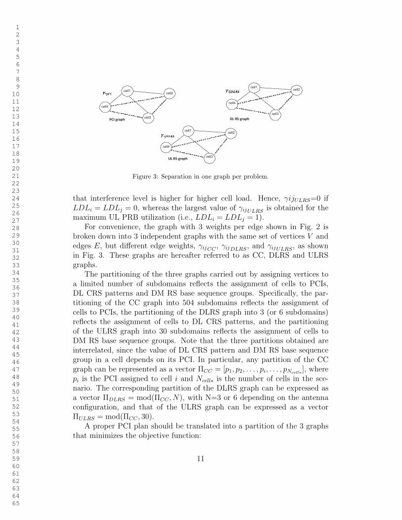
Figure 3: Separation in one graph per problem.
that interference level is higher for higher cell load. Hence, γijULRS=0 ifLDLi = LDLj = 0, whereas the largest value of γijULRS is obtained for themaximum UL PRB utilization (i.e., LDLi = LDLj = 1).
For convenience, the graph with 3 weights per edge shown in Fig. 2 isbroken down into 3 independent graphs with the same set of vertices V andedges E, but different edge weights, γijCC , γijDLRS, and γijULRS, as shownin Fig. 3. These graphs are hereafter referred to as CC, DLRS and ULRSgraphs.
The partitioning of the three graphs carried out by assigning vertices toa limited number of subdomains reflects the assignment of cells to PCIs,DL CRS patterns and DM RS base sequence groups. Specifically, the par-titioning of the CC graph into 504 subdomains reflects the assignment ofcells to PCIs, the partitioning of the DLRS graph into 3 (or 6 subdomains)reflects the assignment of cells to DL CRS patterns, and the partitioningof the ULRS graph into 30 subdomains reflects the assignment of cells toDM RS base sequence groups. Note that the three partitions obtained areinterrelated, since the value of DL CRS pattern and DM RS base sequencegroup in a cell depends on its PCI. In particular, any partition of the CCgraph can be represented as a vector ΠCC = [p1, p2, . . . , pi, . . . , pNcells
], wherepi is the PCI assigned to cell i and Ncells is the number of cells in the sce-nario. The corresponding partition of the DLRS graph can be expressed asa vector ΠDLRS = mod(ΠCC , N), with N=3 or 6 depending on the antennaconfiguration, and that of the ULRS graph can be expressed as a vectorΠULRS = mod(ΠCC , 30).
A proper PCI plan should be translated into a partition of the 3 graphsthat minimizes the objective function:
11
1 2 3 4 5 6 7 8 9 10 11 12 13 14 15 16 17 18 19 20 21 22 23 24 25 26 27 28 29 30 31 32 33 34 35 36 37 38 39 40 41 42 43 44 45 46 47 48 49 50 51 52 53 54 55 56 57 58 59 60 61 62 63 64 65
F (ΠCC) =
F1(ΠCC) if MIMO or MISO
F2(ΠCC) if SISO or SIMO ,(10)
where
F1(ΠCC) =∑
(i,j)∈EΠCC(i)=ΠCC(j)
γijCC+
∑(i,j)∈E1
mod(ΠCC(i),3)= mod (ΠCC(j),3)
γijDLRS+
∑(i,j)∈E1
mod (ΠCC(i),30)= mod (ΠCC(j),30)
γijULRS, (11)
F2(ΠCC) =∑
(i,j)∈EΠCC(i)=ΠCC(j)
γijCC+
∑(i,j)∈E1
mod (ΠCC(i),6)= mod (ΠCC(j),6)
γijDLRS+
∑(i,j)∈E1
mod (ΠCC(i),30)= mod (ΠCC(j),30)
γijULRS, (12)
i.e., the total sum of the weight of edges joining vertices assigned to the samesubdomain in the three graphs. The first addend is the total weight of edgesjoining vertices that share the same PCI value. The second addend is thetotal weight of edges joining vertices sharing the same PCI mod 6 (or PCImod 3), representing cells with the same DL CRS pattern. The third addendis the total weight of edges joining vertices sharing the same PCI mod 30,representing cells with the same UL DM RS base sequence.
2.3. Re-formulation as a graph partitioning problem
To find an optimized PCI plan, any classical graph coloring algorithmcan be adapted to deal with the three graphs (i.e., CC, DLRS and ULRS)in parallel. In this work, the graph coloring problem is re-formulated as agraph partitioning problem to take advantage of existing software. Thus,the problem stands for the partition of the three graphs such that the totaledge cut (i.e., the sum of the weight of edges between vertices in differentsubdomains in the three graphs),
∑(i,j)∈δ(ΠCC)
γijCC+
∑(i,j)∈δ(ΠDLRS)
γijDLRS+
∑(i,j)∈δ(ΠULRS)
γijULRS, (13)
12

1 2 3 4 5 6 7 8 9 10 11 12 13 14 15 16 17 18 19 20 21 22 23 24 25 26 27 28 29 30 31 32 33 34 35 36 37 38 39 40 41 42 43 44 45 46 47 48 49 50 51 52 53 54 55 56 57 58 59 60 61 62 63 64 65
is maximized, where δ(ΠCC), δ(ΠDLRS) and δ(ΠULRS) are the set of edgesjoining vertices in different subdomains in the three graphs with partitionsΠCC , ΠDLRS and ΠULRS.
In the classical version of the graph partitioning problem, the goal isto minimize the edge cut [37]. The minimization problem can easily beconverted into a maximization problem just by changing the sign of edgeweights in the graphs.
3. Graph partitioning algorithm
The graph partitioning problem is known to be NP-hard [38]. For thisreason, many heuristic graph partitioning algorithms have been proposed inthe literature [39]. In this work, a classical multi-level refinement algorithm isadapted to solve the PCI planning problem as a multi-objective optimizationproblem [40].
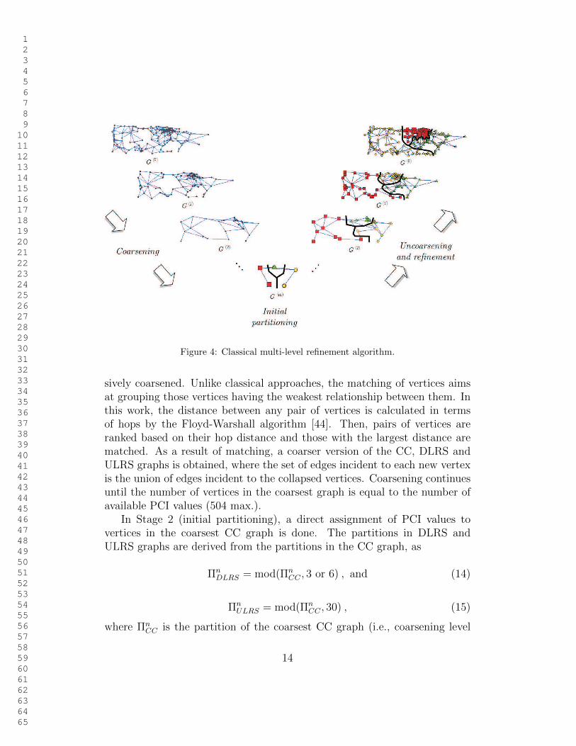
Fig. 4 shows the structure of a classical multi-level refinement algorithmfor graph partitioning, consisting of three stages: graph coarsening, initialpartitioning and graph uncoarsening [39]. In the coarsening phase, the graphis simplified by collapsing vertices together to form single vertices in a higherlevel graph. A series of graphs, G0, G1, ...,Gm, is thus obtained as succes-sive simplifications of the original graph, G0. Coarsening continues until thenumber of vertices in the coarsened graph is slightly equal to the desired num-ber of subdomains. In the simplest graph, a high-quality initial partitioningis built with a low computational load. For this purpose, any basic graphpartitioning algorithm can be used (e.g., multiple randomized attempts [41],graph walking [42]). Then, the partition in the coarsest graph is projectedback to the original graph in the uncoarsening stage by unfolding vertices.After each uncoarsening step, a local refinement algorithm (e.g., greedy orFiduccia-Mattheyses [43]) is used to improve the quality of the partition byre-assigning vertices to other subdomains. For computational efficiency, re-finement is only performed in the border of subdomains. Experiments showsthat, in cellular network graphs, multi-level refinement outperforms otherapproaches in terms of both solution quality and execution time [37].
In this work, a classical multi-level graph partitioning algorithm is con-verted into a graph coloring algorithm for PCI planning. Fig. 5 shows thepseudocode of the algorithm.
In Stage 0 (graph construction), the graph structure is built as explainedin Section 2.2. Then, in Stage 1 (coarsening), the original graph is progres-
13
1 2 3 4 5 6 7 8 9 10 11 12 13 14 15 16 17 18 19 20 21 22 23 24 25 26 27 28 29 30 31 32 33 34 35 36 37 38 39 40 41 42 43 44 45 46 47 48 49 50 51 52 53 54 55 56 57 58 59 60 61 62 63 64 65
Figure 4: Classical multi-level refinement algorithm.
sively coarsened. Unlike classical approaches, the matching of vertices aimsat grouping those vertices having the weakest relationship between them. Inthis work, the distance between any pair of vertices is calculated in termsof hops by the Floyd-Warshall algorithm [44]. Then, pairs of vertices areranked based on their hop distance and those with the largest distance arematched. As a result of matching, a coarser version of the CC, DLRS andULRS graphs is obtained, where the set of edges incident to each new vertexis the union of edges incident to the collapsed vertices. Coarsening continuesuntil the number of vertices in the coarsest graph is equal to the number ofavailable PCI values (504 max.).
In Stage 2 (initial partitioning), a direct assignment of PCI values tovertices in the coarsest CC graph is done. The partitions in DLRS andULRS graphs are derived from the partitions in the CC graph, as
ΠnDLRS = mod(Πn
CC , 3 or 6) , and (14)
ΠnULRS = mod(Πn
CC , 30) , (15)
where ΠnCC is the partition of the coarsest CC graph (i.e., coarsening level
14

1 2 3 4 5 6 7 8 9 10 11 12 13 14 15 16 17 18 19 20 21 22 23 24 25 26 27 28 29 30 31 32 33 34 35 36 37 38 39 40 41 42 43 44 45 46 47 48 49 50 51 52 53 54 55 56 57 58 59 60 61 62 63 64 65
Function Graph_Coloring_Algorithm (C, HOij , P )
Inputs: C ≡ list of cells, HOij ≡ handover statistics, P ≡ set of available PCI values,
Output: Partition of CC graph, ΠCC (i.e., PCI plan)
% Stage 0: Graph constructionBuild basic network graph, G = (V, E)
V ≡ cells, E = E1UE2, E1 ≡ adjacencies with handovers, E2 ≡ adjacencies betweenneighbors of same cell
Compute edge weights, γij = (γijCC, γijDLRS
, γijULRS)
γijCC[Eq. (5)-(7)], γijDLRS
[Eq. (8)], γijULRS[Eq. (9)]
Separate basic network graph into three graphs GCC , GDLRS , GULRS
GCC = (V, E)\γij=γijCC, GDLRS = (V,E)\γij=γijDLRS
, GULRS = (V, E)\γij=γijULRS
% Stage 1: Coarsening stageRepeat % Different coarsening levels
Compute distance in hops between each pair of vertices by Floyd-Warshall algorithmRank pair of vertices in terms of hop distance in descending orderRepeat % Different pair of vertices in the same graph
Select next pair of unmatched vertices with the largest hop distanceuntil all vertices are matched or the number of vertices in coarser graph is equal tothe number of available PCI values
Build coarser version of CC, DLRS and ULRS graph by joining matched verticesuntil the number of vertices in coarser graph is equal to the number of availablePCI values
% Stage 2: Initial partitioningBuild partition for CC graph by direct assignment of subdomain index in the coarsest graph
ΠnCC = P
Derive partitions for DLRS and ULRS graphs from partition in CC graphΠn
DLRS = mod(ΠnCC , 3 or 6) [Eq. (14)], Πn
ULRS = mod(ΠnCC , 30) [Eq. (15)]
% Stage 3: Uncoarsening stageRepeat
Uncoarsen coarser version of CC, DL and ULRS graphs based on matching schemeUncoarsen coarser version of CC, DL and ULRS partitions based on matching schemeRefine partition in CC graph by modified Fiduccia-Matheysses algorithm (Fig. 6)
until the finer graph is the original graphDerive partitions for the original DLRS and ULRS graphs from partition in original CC graph
Π0DLRS = mod(Π0
CC , 3 or 6) [Eq. (14)], Π0ULRS = mod(Π0
CC , 30) [Eq. (15)]
Figure 5: Pseudocode of the graph coloring algorithm for PCI planning.
15
1 2 3 4 5 6 7 8 9 10 11 12 13 14 15 16 17 18 19 20 21 22 23 24 25 26 27 28 29 30 31 32 33 34 35 36 37 38 39 40 41 42 43 44 45 46 47 48 49 50 51 52 53 54 55 56 57 58 59 60 61 62 63 64 65
n), and the value of 3 or 6 in (14) depends on antenna configuration.In Stage 3 (uncoarsening), the three graphs and partitions are unfolded
following the matching scheme obtained in the coarsening stage. After eachuncoarsening operation, the CC graph partition is refined by a modified ver-sion of the Fiduccia-Mattheyses local refinement algorithm [43]. The pseu-docode of the algorithm is shown in Fig. 6. The algorithm consists of aseries of passes. In each pass, the algorithm first computes the gain fromre-assigning every vertex (i.e., cell), i, from the current subdomain, p, to adifferent subdomain, p′, in the CC graph, as
g(i, p′) = ∆F (ΠCC) = F (ΠCC)|ΠCC(i)=p − F (ΠCC)|ΠCC(i)=p′ = ∑(i,j)∈E
ΠCC(i)=ΠCC(j)
γijCC
∣∣∣∣∣ΠCC(i)=p
−∑
(i,j)∈EΠCC(i)=ΠCC(j)
γijCC
∣∣∣∣∣ΠCC(i)=p′
+
∑(i,j)∈E1
ΠDLRS(i)=ΠDLRS(j)
γijDLRS
∣∣∣∣∣ΠCC(i)=p
−∑
(i,j)∈E1
ΠDLRS(i)=ΠDLRS(j)
γijDLRS
∣∣∣∣∣ΠCC(i)=p′
+
∑(i,j)∈E1
ΠULRS(i)=ΠULRS(j)
γijULRS
∣∣∣∣∣ΠCC(i)=p
−∑
(i,j)∈E1
ΠULRS(i)=ΠULRS(j)
γijULRS
∣∣∣∣∣ΠCC(i)=p′
.
(16)
For each vertex, the best target subdomain, p∗(i), is selected as the onewith the maximum gain, g∗(i). Then, the vertex with the largest potentialgain is moved, and marked so that it is discarded for the rest of the pass.This process is repeated until there are no unmarked nodes. Note that anyre-assignment of a vertex to a different subdomain in the CC graph requiresupdating the partition in the DLRS and ULRS graphs by (14) and (15). Aftereach pass, the solution with the lowest cost, F (ΠCC), is selected. To reducethe computational load, refinement is only performed on vertices sharingsubdomain with its adjacent vertices, i.e., vertices that have equal PCI,mod(PCI, 3 or 6), or mod(PCI, 30). Likewise, vertices can be re-assignedto any subdomain when refining a partition (and not only to the subdomainsof its adjacent vertices, as in classical graph partitioning).
16

1 2 3 4 5 6 7 8 9 10 11 12 13 14 15 16 17 18 19 20 21 22 23 24 25 26 27 28 29 30 31 32 33 34 35 36 37 38 39 40 41 42 43 44 45 46 47 48 49 50 51 52 53 54 55 56 57 58 59 60 61 62 63 64 65
Function Local Refinement (GCC , GDLRS, GULRS, ΠCC)
Inputs: CC/DLRS/ULRS graphs GCC , GDLRS, GULRS, CC partitition ΠCC
Output: Refined CC partition, Π′CC
For a pre-determined number of iterations
Set the state of every node to unmarked
Derive DLRS and ULRS partitions from CC partition
ΠnDLRS = mod(Πn
CC , 3 or 6) [Eq. (14)], ΠnULRS = mod(Πn
CC , 30) [Eq. (15)]
For each vertex i
Compute largest potential gain from assigning vertex i to a different subdomain P (i)
g(i, p′) = ∆F (ΠCC) = F (ΠCC)|ΠCC(i)=p − F (ΠCC)|ΠCC(i)=p′ [Eq. (16)]
g∗(i) = maxp′g(i, p′)
p∗(i) = argmaxp′g(i, p′)
End
Rank unmarked vertices in terms of g∗(i)
Repeat % re-assignment of a vertex
Select unmarked vertex i with largest g∗(i)
Re-assign i to subdomain p∗(i)
Set the state of re-assigned node i to marked
Update partition in DLRS and ULRS graphs
Π0DLRS = mod(Π0
CC , 3 or 6) [Eq. (14)], Π0ULRS = mod(Π0
CC , 30) [Eq. (15)]
Save intermediate CC partition and compute intermediate overall cost F (ΠCC)
F (ΠCC) =∑
(i,j)∈EΠCC(i)=ΠCC(j)
γijCC+
∑(i,j)∈E1
ΠDLRS(i)=ΠDLRS(j)
γijDLRS+
∑(i,j)∈E1
ΠULRS(i)=ΠULRS(j)
γijULRS[Eq.(10)]
Update potential gains and best target subdomains of unmarked vertices, g∗(i)
and p∗(i)
until there are no unmarked nodes or the number of consecutive movements without
reducing the overall cost exceeds a certain limit
Restore intermediate solution with lowest overall cost
End
Figure 6: Pseudocode of modified Fiduccia-Mattheyses algorithm.
17

1 2 3 4 5 6 7 8 9 10 11 12 13 14 15 16 17 18 19 20 21 22 23 24 25 26 27 28 29 30 31 32 33 34 35 36 37 38 39 40 41 42 43 44 45 46 47 48 49 50 51 52 53 54 55 56 57 58 59 60 61 62 63 64 65
The theoretical worst-case time complexity of the proposed multi-refinementalgorithm is that of the Floyd-Warshall algorithm for computing the distancebetween vertices, i.e., O(|V |3), where |V | is the number of vertices in thegraph [45]. In practice, the execution time is dominated by the computa-tional load of the local refinement algorithm, which grows linear with thenumber of vertices in the graphs [43].
4. Performance analysis
The proposed method is tested in a problem instance constructed withdata taken from a live LTE network. For clarity, the analysis set-up is firstdescribed and results are presented later.
4.1. Analysis set-up
The algorithm is tested with real data taken from 620 LTE cells, coveringa seamless geographical area of 290 km2. Fig. 7 shows the network graphof the area. Vertices in the graph, representing cells, are located in thelocation of the corresponding base stations. Edges in the graph representadjacencies between cells. Two cells are considered adjacent if there arehandovers between them, which is derived from handover statistics. In thefigure, it is observed that some cells are isolated, since they do not haveincoming or outgoing handovers. It is assumed that these cells do not causecollision or confusion problems, as they are isolated.
The inputs of the algorithm are collected from configuration parameters(i.e., neighbor cell list and antenna configuration) and performance measure-ments (i.e., handovers) in the network management system. From this data,the network graph is constructed. Edges are derived from handover statis-tics, while edge weights are computed from priority factor parameters andhandover and cell load statistics by (5)-(9). For ease of analysis, it is as-sumed that the cell load (i.e., PRB utilization ratio) is the same for all cellsin both DL and UL cases, i.e., LDL = LUL = 50%. By eliminating theinfluence of cell load on CRS and DM RS collision probability, it is easier toshow the impact of priority weights on the number of collisions. Likewise, itis assumed that base sequence group hopping is disabled in the UL, as it isnormally the case in live networks.
Six different PCI planning approaches are tested. Four are obtained withthe proposed algorithm by configuring internal parameters CollW , ConfW ,DLRSW and ULRSW as described below:
18

1 2 3 4 5 6 7 8 9 10 11 12 13 14 15 16 17 18 19 20 21 22 23 24 25 26 27 28 29 30 31 32 33 34 35 36 37 38 39 40 41 42 43 44 45 46 47 48 49 50 51 52 53 54 55 56 57 58 59 60 61 62 63 64 65
• Random plan. PCI plan is built by assigning PCI to cells randomly. Toimprove solution quality with this option, 100 random plans are builtand the one with the best quality is selected.
• CollConf plan. PCI plan is designed to avoid PCI collisions and con-fusion problems. For this purpose, the proposed solution algorithm isconfigured with CollW = ConfW = 1, DLRSW = 0, ULRSW = 0.
• DL plan. PCI plan is designed to minimize the number of DL RScollisions. As PRB utilization is the same for all cells, this plan aims toreduce the number of DL RS collisions in the network. For this purpose,the proposed algorithm is configured with CollW = ConfW = 0,DLRSW = 1, ULRSW = 0.
• UL plan. PCI plan is designed to minimize the number of UL RScollisions. For this purpose, the proposed algorithm is configured withCollW = ConfW = 0, DLRSW = 0, ULRSW = 1.
• CollConfDLUL plan. PCI plan is built taking into account all restric-tions. For this purpose, the proposed algorithm is configured withCollW = ConfW = 1, DLRSW = 1, ULRSW = 1.
• Baseline plan. PCI plan currently implemented in the live network,which only takes PCI collision and confusion problems into account.
In the CollConf, DL, UL and CollConfDLUL plans, the best partition isconstructed by executing the above-described multilevel refinement algorithmover the graphs built with different priority weights. By using the sameheuristic algorithm in all four approaches, it is intended to show the impactof formulating the problem with different constraints. It is expected thatthe proposed multi-level refinement algorithm should give very high qualitysolutions, as reported in [40]. All these plans are deterministic, unlike the onefrom the random approach, which is the best of 100 randomized attempts.
The key performance indicators used to assess the quality of a PCI planare: a) the number of adjacencies with PCI collision/confusion problems,and b) the total number of handovers between cells whose RSs collide inDL or UL. The aim of using handovers figures, instead of the raw numberof adjacencies where collisions occur, is to quantify not only the numberof RS collisions, but also that the severity of these collisions in terms ofinterference. Thus, a proper PCI plan should not only reduce the number
19
1 2 3 4 5 6 7 8 9 10 11 12 13 14 15 16 17 18 19 20 21 22 23 24 25 26 27 28 29 30 31 32 33 34 35 36 37 38 39 40 41 42 43 44 45 46 47 48 49 50 51 52 53 54 55 56 57 58 59 60 61 62 63 64 65
Figure 7: Network graph.
Table 1: Comparison between different PCI plansPlans PCI collisions PCI confusions DL RS collisions UL RS collisions
[adjacencies] [adjacencies] [handovers] [handovers]Random 10 35 6243 (-3.22%) 567 (-77.18%)Baseline 0 0 6048 320CollConf plan 0 0 4248 (29.76%) 90 (71.87%)DL plan 0 2 1634 (72.98%) 86 (73.125%)UL plan 0 3 3788 (37.36%) 24 (92.5%)CollConfDLUL plan 0 0 2338 (61.55%) 52 (83.75%)
of collisions between cells, but also avoid those with the largest interferencelevels. It is assumed here that those adjacencies with the largest numberof handovers are normally geographically closer than others. The executiontime is also used as a secondary performance criterion. For that purpose,the different routines were run on a Windows-based computer with a clockfrequency of 2.6 GHz and 8 GB of RAM.
4.2. Analysis results
Table 1 shows the results of the different PCI plans, including the numberof adjacencies with PCI collision and confusion problems, and the numberof handovers between cells sharing DL CRS and PUCCH DM RS. For com-parison purposes, the improvement obtained by each plan compared to theoperator plan (baseline) is shown in parentheses. An inspection of the table
20
1 2 3 4 5 6 7 8 9 10 11 12 13 14 15 16 17 18 19 20 21 22 23 24 25 26 27 28 29 30 31 32 33 34 35 36 37 38 39 40 41 42 43 44 45 46 47 48 49 50 51 52 53 54 55 56 57 58 59 60 61 62 63 64 65
(a) PSS plan (PCI mod 3) (b) DMRS sequence plan (PCI mod 30)
Figure 8: DL PSS and UL DM RS plans obtained with the proposed method.
shows that PCIs cannot be assigned randomly, because that leads to manyPCI collision and confusion problems (specifically, 45 for a cluster of 620cells). In contrast, the baseline plan currently implemented in the real net-work manages to avoid collision and confusion problems, but the number ofDL CRS and UL DM RS collisions is close to that obtained with the randomPCI plan. The other plans, built with the proposed method, focus on thecriterion prioritized by the selected internal parameter settings (either PCIcollision/confusion, DL RS or UL RS). In particular, the CollConfplan planreduces PCI collision/confusion events to 0 by forcing that all edges in thePCI graph have non-negative weights. However, DL RS and UL RS collisionsare only decreased by 29.76% and 71.87% respectively. This is clear evidenceof the need for considering UL and DL RS collisions when building a PCIplan. DL/UL plans reduce DL/UL RS collisions even further, at the expenseof causing some PCI confusion problems. This result points out the need foralso considering PCI collisions and confusions when optimizing DL and ULRS plans. The best tradeoff among all criteria is achieved by the CollConfD-LUL plan, as it eliminates PCI collision/confusion problems, while obtainingDL and UL collision figures close to the ones obtained by plans specificallydesigned for these criteria.
Fig. 8 shows the DL PSS and UL base sequence plans built with theCollConfDLUL solution on a map. By eliminating collision problems be-tween adjacent cells at different levels, the resulting plans would improve DLchannel quality estimates and reduce the number of PUCCH failures, which
21

1 2 3 4 5 6 7 8 9 10 11 12 13 14 15 16 17 18 19 20 21 22 23 24 25 26 27 28 29 30 31 32 33 34 35 36 37 38 39 40 41 42 43 44 45 46 47 48 49 50 51 52 53 54 55 56 57 58 59 60 61 62 63 64 65
40
50
60
70
80
90
100
Rel
ativ
e im
prov
emen
t (%
)
DL and UL priority parameters
DLRSW=1ULRSW=0(DL plan)
DLRSW=0.75ULRSW=0.25
DLRSW=0.5ULRSW=0.5
DLRSW=0.25ULRSW=0.75
DLRSW=0ULRSW=1(UL plan)
UL RS collisionsDL RS collisions
Figure 9: Tradeoff between UL and DL collision performance.
should translate into more robust mobility procedures and higher DL andUL user throughput.
To check the tradeoff between UL and DL performance, the algorithmis tested with different priority settings for ULRSW and DLRSW . Fig. 9shows the relative improvement in the number of DL CRS and UL DMRS co-llisions compared to the operator solution. Note that the combinations on theleft and right of the figure correspond to the DL and UL plans, whose perfor-mance is shown in Table 1. As expected, the higher the priority given to theUL, the larger the reduction in DM-RS collisions. It is also observed that halfof the maximum potential gain from a careful planning of UL DM RSs can beachieved by increasing DL CRS collisions only by 10% (for DLRSW=0.75and ULRSW=0.25 settings).
Table 2 shows the execution times of the different approaches. It is ob-served that the randomized approach is executed almost instantly. In the100 attempts tested, the average value is 0.0092 seconds with a 95-th per-centile confidence interval of [0.002-0.0312] seconds. In contrast, the proposedapproach, CollConfDLUL, takes 720 seconds. This time is short enough touse the method for network planning purposes.
22

1 2 3 4 5 6 7 8 9 10 11 12 13 14 15 16 17 18 19 20 21 22 23 24 25 26 27 28 29 30 31 32 33 34 35 36 37 38 39 40 41 42 43 44 45 46 47 48 49 50 51 52 53 54 55 56 57 58 59 60 61 62 63 64 65
Table 2: Execution time for different PCI planning methodsPlans Random CollConf plan DL plan UL plan CollConfDLUL planExecution time [s] 0.0092 [0.002-0.0312] 124 660 320 720
5. Conclusions
In this paper, a heuristic self-planning method for Physical Cell Identifiersin an LTE system based on configuration and performance data in the net-work management system has been proposed. Unlike previous approaches,which were focused on isolated issues caused by PCIs, the proposed methodmanages to reduce PCI collision/confusion problems, DL CRS collisions andPUCCH DM RS collisions simultaneously. For this purpose, the assign-ment of PCIs has been formulated as a multi-objective graph partitioningproblem, which is later solved by a multi-level refinement graph partitioningalgorithm. Performance assessment has been carried out on graphs construc-ted from data collected in live LTE network. Results show that the algorithmcan eliminate PCI collision and confusion problems, while reducing DL RScollisions by 62% and UL RS collisions by 84% compared to the solution cu-rrently implemented in the network. As already pointed out in [26], the needfor the proposed algorithm will be larger in future ultra-dense heterogeneousscenarios, where the common strategy of defining PCI subsets for each layerreduces the number of available PCI values.
The proposed method can be implemented as a centralized or a dis-tributed solution. In the centralized solution, base stations (enodeBs) takehandover and cell load measurements. This data is periodically uploaded inthe network management system, where a centralized version of the proposedPCI planning algorithm is executed. Then, the output of the algorithm (i.e.,the PCI value assigned to each cell) is sent back to the enodeB and broad-casted to the user in a common control channel. In the distributed solution,each enodeB must exchange with surrounding enodeBs the information re-quired to build a small portion of the graph, i.e., PCI list, handovers and cellload measurements. This information can be periodically exchanged throughthe X2 interface between adjacent cells. Then, a local refinement algorithmcan be executed to decide the re-assignment of PCIs so as to reduce collisionand confusion problems with surrounding cells.
23

1 2 3 4 5 6 7 8 9 10 11 12 13 14 15 16 17 18 19 20 21 22 23 24 25 26 27 28 29 30 31 32 33 34 35 36 37 38 39 40 41 42 43 44 45 46 47 48 49 50 51 52 53 54 55 56 57 58 59 60 61 62 63 64 65
Acknowledgement
This work has been funded by the Spanish Ministry of Economy andCompetitiveness (TEC2015-69982-R) and Ericsson, Agencia IDEA (Conse-jerıa de Ciencia, Innovacion y Empresa, Junta de Andalucıa, ref. 59288) andFEDER.
References
[1] J. Ramiro, Self-Organizing Networks: Self-Planning, Self-Optimizationand Self-Healing for GSM, UMTS and LTE, John Wiley & Sons, 2011.
[2] 3G Americas, The benefits of SON in LTE: Self-Optimizing and Self-Organizing Networks, Technical Report, 2009.
[3] 3rd Generation Parthnership Project, Technical Specification GroupRadio Access Network; Evolved Universal Terrestrial Radio AccessNetwork (E-UTRAN); Self-Configuring and Self-Optimizing Network(SON) Use Cases and Solutions (Release 9), TR 36.902 V9.3.1, TechnicalReport, 2011.
[4] 3rd Generation Parthnership Project, Technical Specification Group Ra-dio Access Network; Evolved Universal Terrestrial Radio Access Net-work (E-UTRA); Physical Channel and Modulation (Release 11), TR36.211 V11.2.0, Technical Report, 2013.
[5] S. Sesia, I. Toufik, M. Baker, LTE: The UMTS Long Term Evolution,From Theory to Practice, Wiley, 2009.
[6] J. Zyren, D. McCoy, Overview of the 3GPP Long Term Evolution Phy-sical Layer, Technical Report, Freescale Semiconductor, 2007.
[7] H. Holma, A. Toskala, LTE for UMTS: Evolution to LTE-Advanced,John Wiley & Sons, UK, 2011.
[8] T. Bandh, G. Carle, H. Sanneck, Graph coloring based Physical-Cell-IDassignment for LTE networks, in: Wireless Communications and MobileComputing, 2009, pp. 116–120.
[9] F. Ahmed, O. Tirkkonen, M. Peltomki, M. A. Juha-Matti KoljonenChia-Hao Yu, Distributed graph Coloring for Self-Organization in LTEnetworks, Journal of Electrical and Computer Engineering (2010).
24
1 2 3 4 5 6 7 8 9 10 11 12 13 14 15 16 17 18 19 20 21 22 23 24 25 26 27 28 29 30 31 32 33 34 35 36 37 38 39 40 41 42 43 44 45 46 47 48 49 50 51 52 53 54 55 56 57 58 59 60 61 62 63 64 65
[10] H. Xu, X. W. Zhou, Y. Li, Model of hypergraph colouring for Self-configuration in LTE Networks, in: International Conference on Infor-mation Management, Innovation Management and Industrial Engineer-ing (ICIII), 2011, volume 1.
[11] Z. Matloub, I. Kostaric, Methodology for the physical cell identityassignment in lte networks, International Journal of Networks andCommunications 3 (5) (2013) 111–117.
[12] Y. Liu, W. Li, H. Zhang, W. Lu, Graph based automatic centralized PCIassignment in LTE, in: IEEE Symposium on Computers and Commu-nications (ISCC), 2010, pp. 919 –921.
[13] Y. Wei, M. Peng, W. Wang, S. Min, J. M. Jiang, Y. Huang, Auto-matic Distributing Schemes of Physical Cell Identity for Self-OrganizingNetworks, International Journal of Distributed Sensor Networks (2012).
[14] Y. Liu, W. Li, H. Zhang, L.Yu, Distributed PCI assignment in LTEbased on consultation mechanism, in: Wireless Communications Net-working and Mobile Computing (WiCOM), (2010), pp. 1–4.
[15] J. Oppolzer, R. Bestak, Physical Cell Identifier assignment in LTE-advanced networks, in: 5th Joint IFIP Wireless and Mobile NetworkingConference (WMNC), 2012, pp. 70–74.
[16] P. Lee, J. Jeong, N. Saxena, J. Shin, Dynamic reservation scheme of phy-sical cell identity for 3gpp lte femtocell systems, Journal of InformationProcessing Systems 5 (2007) 207–220.
[17] T. Wu, L. Rui, A. Xiong, S. Guo, An Automation PCI allocationmethod for enodeB and home enodeB cell, in: 6th International Confer-ence on Wireless Communications Networking and Mobile Computing(WiCOM), 2010.
[18] Y. Wu, H. Jiang, Y. Wu, D. Zhang, Physical Cell Identity Self-Organization for Home eNodeB Deployment in LTE, in: 6th Interna-tional Conference on Wireless Communications Networking and MobileComputing (WiCOM), pp. 1–6.
25

1 2 3 4 5 6 7 8 9 10 11 12 13 14 15 16 17 18 19 20 21 22 23 24 25 26 27 28 29 30 31 32 33 34 35 36 37 38 39 40 41 42 43 44 45 46 47 48 49 50 51 52 53 54 55 56 57 58 59 60 61 62 63 64 65
[19] X. Zhang, D. Zhou, Z. Xiao, E. Liu, J. Zhang, A. Glasunov, Dynamicgroup PCI assignment scheme, in: The 7th Int. Conference on Wirelessand Mobile Communications, ICWMC, 2011, pp. 101–106.
[20] J. Lim, H. Daehyoung, Management of Neighbor Cell lists and PhysicalCell Identifiers in Self-Organizing heterogeneous networks, Journal ofCommunications and Networks 13 (2011) pp. 367–376.
[21] A. Zahran, Extended Synchronization Signals for eliminating PCI con-fusion in heterogeneous LTE, in: IEEE Wireless Communications andNetworking Conference (WCNC), 2012, pp. 2588–2592.
[22] M. Krichen, D. Barth, O.Marce, Performances Evaluation of differentAlgorithms for PCIs Self Configuration in LTE, in: 18th IEEE Interna-tional Conference onNetworks (ICON), 2012, pp. 197–203.
[23] O. Teyeb, G. Mildh, A. Furuskr, Physical cell identity assignment in het-erogeneous networks, in: IEE Vehicular Technology Conference (VTCFall), pp. 1–5.
[24] P. Szilagyi, T. Bandh, H. Sanneck, Physical cell id allocation in multi-layer, multi-vendor LTE networks, Mobile Networks and Management(Springer) (2013) 156–168.
[25] F. Ahmed, O. Tirkkonen, Self Organized Physical Cell ID Assignment inMulti-Operator Heterogeneous Networks, in: 2015 IEEE 81st VehicularTechnology Conference (VTC Spring), Glasgow, pp. 1–5.
[26] S. S. Mwanje, J. Ali-Tolppa, H. Sanneck, On the Limits of PCI AutoConfiguration and Reuse in 4G/5G Ultra Dense Networks, in: 11thInternational Conference on Network and Service Management (CNSM),2015, pp. 92–98.
[27] A. Gupta, R. K. Jha, A survey of 5g network: Architecture and emergingtechnologies, IEEE Access (2015) 1206–1232.
[28] E. Fredik Egrelius, Method and arrangement for PCI assignment,wo2014/120056 a1, 2014.
[29] H. Sun, N. Li, Y. Chen, J. Dong, N. Liu, Y. Han, W. Liu, A method ofPCI planning in LTE based on genetic algorithm, Progress In Electro-magnetics Research Symposium, Moscow, Russia (2012) pp. 19–23.
26
1 2 3 4 5 6 7 8 9 10 11 12 13 14 15 16 17 18 19 20 21 22 23 24 25 26 27 28 29 30 31 32 33 34 35 36 37 38 39 40 41 42 43 44 45 46 47 48 49 50 51 52 53 54 55 56 57 58 59 60 61 62 63 64 65
[30] G. Karypis, V. Kumar, A Software Package for Partitioning Unstruc-tured Graphs, Partitioning Meshes, and Computing Fill-Reducing Or-derings of Sparse Matrices, Version 4.0, Technical Report, University ofMinnesota, Departament of Computer Science / Army HPC ResearchCenter, 1998.
[31] C. Walshaw, M. Cross, Jostle: Parallel multilevel graph-partitioningsoftware - an overview, Mesh Partitioning Techniques and Domain De-composition Techniques (2007) 27–58.
[32] Chaco, User guide,https://cfwebprod.sandia.gov/cfdocs/CompResearch/docs/guide.pdf,[Accessed November 2016].
[33] B. Hendrickson, R. Leland, A multilevel algorithm for partitions graphs,in: A. Press (Ed.), ACM/IEE Conference on Supercomputing.
[34] G. Karypis, V. Kumar, Multilevel k-way partitioning scheme for irreg-ular graphs, Journal of Parallel and Distributed Computing 48 (1998)96–129.
[35] C. Walshaw, M. Cross, Mesh partitioning: a multilevel balancing andrefinement algorithm, SIAM Journal of Scientific Computing 22 (2000)66–80.
[36] R. Acedo-Hernandez, M. Toril, S. Luna-Ramırez, I. de la Bandera,N. Faour, Analysis of the impact of PCI planning on downlink through-put performance in LTE, Computer Networks vol. 76 (2015) pp. 42–54.
[37] M. Toril, I. Molina-Fernandez, V. Wille, C. Walshaw, Analysis of Heuris-tic Graph Partitioning Method for the Assignment of Packet ControlUnit in GERAN, Wireless Personal Communications vol. 60 (2011) pp.611–633.
[38] M. R. Garey, D. S. Jonhson, Computers and Intractability: A Guide tothe Theory of NP-Completeness, Freeman, San Francisco, 1979.
[39] K. Schloegel, G. Karypis, V. Kumar, Graph partitioning for high perfor-mance scientific simulations, In CRPC Parallel Computing Handbook,Morgan Kaufmann, 2000.
27

1 2 3 4 5 6 7 8 9 10 11 12 13 14 15 16 17 18 19 20 21 22 23 24 25 26 27 28 29 30 31 32 33 34 35 36 37 38 39 40 41 42 43 44 45 46 47 48 49 50 51 52 53 54 55 56 57 58 59 60 61 62 63 64 65
[40] C. Walshaw, A Multilevel Approarch to the Graph Colouring Problem,Mathematics Research Report 01/IM/69, Computing and MathematicalSciences, University of Greenwich, 2001.
[41] R. Martı, Multistart methods, Handbook on Metaheuristics (2000)355–368.
[42] C. Farhat, A simple and efficient automatic fem domain descomposer,Computers and Structures 28 (1988) 579–602.
[43] C. Fiduccia, R. Mattheyses, A linear-time heuristic for improving net-work partitions, in: Proc 19th ACM/IEEE Design Automation Confer-ence, pp. 175–181.
[44] C. E. Leiserson, T. H. Cormen, C. S. . R. Rivest, Introduction to Algo-rithm, MIT Press, 1990.
[45] T. H. Cormen, C. Stein, R. L. Rivest, C. E. Leiserson, Introduction toAlgorithms, Mc. Graw-Hill Higher Education, 2001.
28