Embed Size (px)
Citation preview

ITT
MM-TM11-01 Technical Manual
RBT-3000Low Water Cut-off and Fuel Economizer
Technical Manual• Operation• Programming• Wiring

Product Description ……………………………...........……………….........……………….... 2
Operation …………………………………………………………....................……………….. 2
Programming ……………………………………………………………...........…......…..…. 3-5
Basic Wiring …………………………………………………………………......................…... 6
Specific WiringBecket Burners
Genesis 7505 Cad Cell Relay ………………………….............………….............……. 7
Carlin Burners
40-200 Cad Cell Relay ………………………………………............….............………. 8
60-200 Cad Cell Relay …………………………………………............…...........…...….8
Riello Burners
Model 40F5 (if experiencing feedback) ………………………...........................…... 18
530 SE/C Control Box ………………………………………….........................……... 16
United Technology Burner Control
UT 1107-1 ………………………………………………………………......................…17
Honeywell Burner Control
L7124A,C,U …….……………………………………………………......................…..….9
L7148A ………………………………………………………….............................…..….9
L7148F …………………………………………………………………......................… 10
L7224A,C,U ……………………....………………………………...........…...........…… 10
L7248A,C …………………………....……………………………...........…...........…… 10
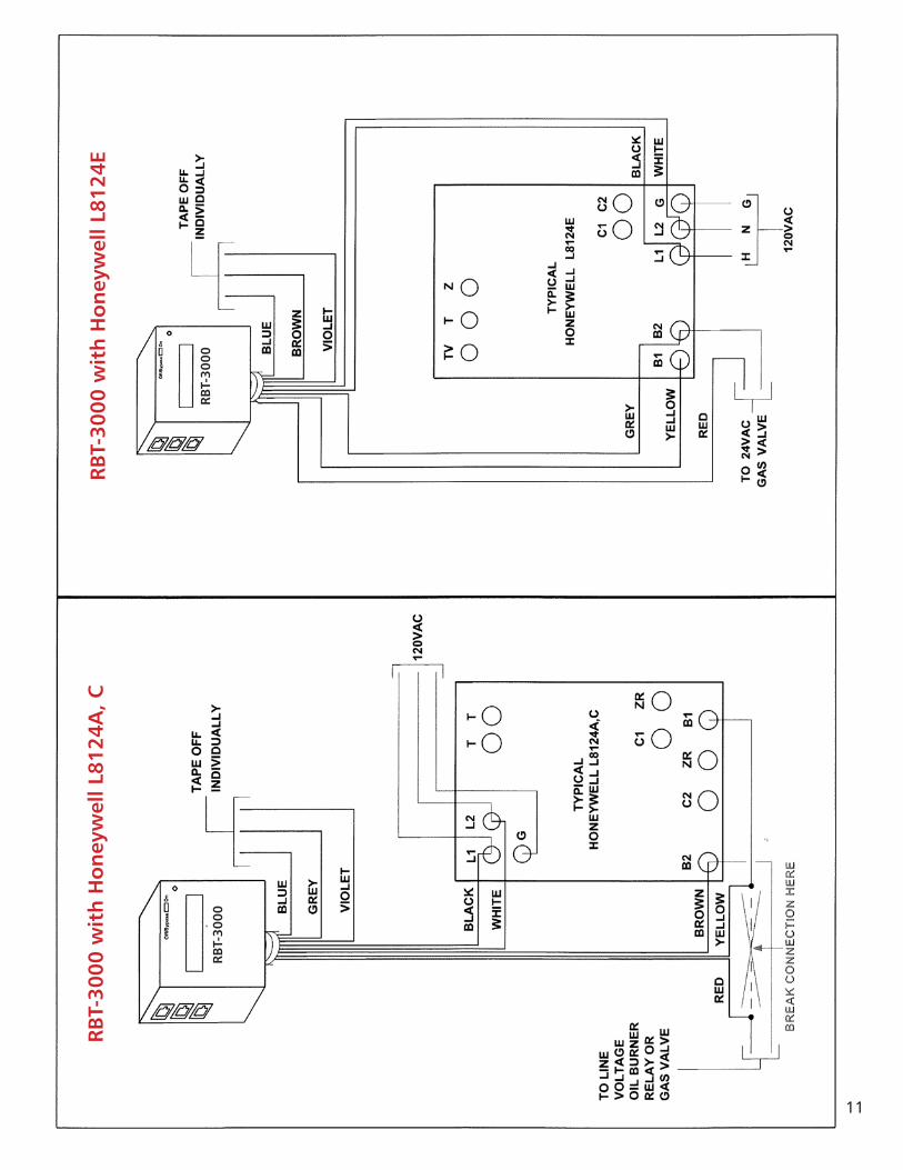
L8124A,C ………………………………………....…………………….......................…11
L8124E ………………………........…………………………………….......................…11
L8124G,L …….………………………………………………………......................…… 19
L8148A ……………………………………………………………......................……… 19
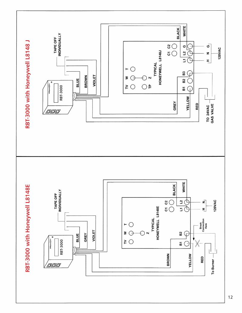
L8148E, J ……………………………...………………………………........................... 12
L8151A ………………………………………………………………….......................…13
R7184A,B,P,U (Low Voltage Controller) Pre Rev. 5 ………………........................… 14
R7184A,B,P,U (Low Voltage Controller) Rev. 5 ………………......................…….… 14
R7184A,B,P,U (Line Voltage Controller) …………………………….......................… 10
R8182D …………………………………………………………………......................… 13
R8182E …………………………………………………………………......................… 15
R8182F, G ………………………………….……………………..........................……. 15
R8285D ………………………………………………………………….......................…17
1
Table of Contents
RBT-3000Low Water Cut-off and Fuel Economizer
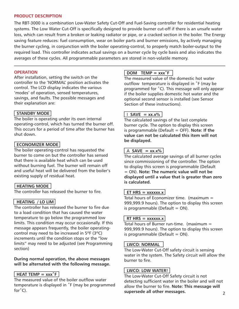
PRODUCT DESCRIPTION
The RBT-3000 is a combination Low-Water Safety Cut-Off and Fuel-Saving controller for residential heating systems. The Low Water Cut-Off is specifically designed to provide burner cut-off if there is an unsafe water loss, which can result from a broken or leaking radiator or pipe, or a cracked section in the boiler. The Energy saving feature reduces: fuel consumption, wear on boiler parts and burner emissions, by actively managing the burner cycling, in conjunction with the boiler operating-control, to properly match boiler-output to the required load. This controller indicates actual savings on a burner cycle by cycle basis and also indicates the averages of these cycles. All programmable parameters are stored in non-volatile memory.
OPERATIONAfter installation, setting the switch on the controller to the ‘NORMAL’ position activates the control. The LCD display indicates the various ‘modes’ of operation, sensed temperatures, savings, and faults. The possible messages and their explanation are:
STANDBY MODE The boiler is operating under its own internal operating-control, which has turned the burner off. This occurs for a period of time after the burner has shut down.
ECONOMIZER MODE The boiler operating-control has requested the burner to come on but the controller has sensed that there is available heat which can be used without burning fuel. The burner will remain off and useful heat will be delivered from the boiler’s existing supply of residual heat.
HEATING MODE The controller has released the burner to fire.
HEATING / LO LIM The controller has released the burner to fire due to a load condition that has caused the water temperature to go below the programmed low limits. This condition may occur occasionally. If this message appears frequently, the boiler operating-control may need to be increased in 5ºF (3ºC) increments until the condition stops or the “low limits” may need to be adjusted (see Programming section)
During normal operation, the above messages will be alternated with the following message.
HEAT TEMP = xxx˚F The measured value of the boiler outflow water temperature is displayed in ˚F (may be programmed for˚C).
DOM TEMP = xxx˚F The measured value of the domestic hot water outflow temperature is displayed in ˚F (may be programmed for ˚C). This message will only appear if the boiler supplies domestic hot water and the optional second sensor is installed (see Sensor Section of these instructions).
I SAVE = xx.x% The calculated savings of the last complete burner cycle. The option to display this screen is programmable (Default = OFF). Note: If the value can not be calculated this item will not be displayed.
A SAVE = xx.x% The calculated average savings of all burner cycles since commissioning of the controller. The option to display this screen is programmable (Default = ON). Note: The numeric value will not be displayed until a value that is greater than zero is calculated.
ET HRS = xxxxxx.x Total hours of Economizer time. (maximum = 999,999.9 hours). The option to display this screen is programmable (Default = ON).
RT HRS = xxxxxx.x Total hours of Burner run-time. (maximum = 999,999.9 hours). The option to display this screen is programmable (Default = ON).
LWCO: NORMAL The Low-Water Cut-Off safety circuit is sensing water in the system. The Safety circuit will allow the burner to fire.
LWCO: LOW WATER! The Low-Water Cut-Off Safety circuit is not detecting sufficient water in the boiler and will not allow the burner to fire. Note: This message will supersede all other messages. 2

PROGRAMMINGThe following parameters may be changed in the field by following these instructions. Pre-Purge time, Temperature indication in either degrees F or C, Heating Water Low-Limit, Domestic Water Low-Limit, Maximum Economizer Hold-Off Time, Standby-Timer Override, and whether or not Economizer Time, Burner Run-Time, I SAVINGS, and A SAVINGS are Displayed. The system may also be returned to factory default values and the Average Savings, Economizer Time, and Run-Time accumulators may be cleared.
ALL OF THE DEFAULT VALUES HAVE BEEN CAREFULLY SELECTED TO RESULT IN THE GREATEST SAVINGS FOR THE BROADEST SCOPE OF HEATING SYSTEM APPLICATIONS. INDIVIDUAL SYSTEM REQUIREMENTS MAY REQUIRE CHANGES. PLEASE NOTE THAT ALL OF THESE PROGRAMMABLE PARAMETERS WILL AFFECT THE AMOUNT OF SAVINGS. PRUDENT CHANGES ARE STRONGLY ADVISED.
It is very important that if there is any kind of a delay (more than fifteen (15) seconds), from the time that the Operating-control calls for the burner to start and the burner actually starts, that this time delay value be entered into the controller as a Pre-Purge time (e.g. actual pre-purge timer, Flue Damper interlock, etc.). If there is a delay and the correct value is not programmed into the controller, the savings calculations will be incorrect.
ALL PROGRAMMING IS ACHIEVED BY INSERTING AND REMOVING A WATER TEMPERATURE SENSOR PLUG INTO THE DOM SENSOR CONNECTOR, WHEN DIRECTED TO DO SO VIA THE DISPLAY ON THE CONTROLLER. THE SENSOR MUST BE CONNECTED TO THE CABLE OR THIS WILL NOT WORK!
YOU HAVE TEN (10) SECONDS TO RESPOND TO ANY OF THE DISPLAY PROMPTS. THE 10 SECOND COUNTDOWN IS DISPLAYED ON THE CONTROLLER’S LCD DISPLAY.
PROGRAMMING MAY BE STOPPED OR ABORTED AT ANY TIME BY ANY PARAMETERS THAT WERE CHANGED WILL REMAIN CHANGED.
Entering Configuration Mode:When prompted insert a water sensor plug into the DOM SENSOR connector. To confirm, remove the plug when prompted. The unit will then indicated
that it has entered “**Config Mode**”. After a 4 second delay the display will advance to the first programmable parameter (RESET DEFAULTS?).
Changes made to a parameter will be confirmed by indicating **DATA SAVED**.
RESET DEFAULTS This parameter will reset all of the programmable parameters to factory defaults. It will not clear any of the accumulators.
RESET SAVINGS This parameter will clear the Average Savings accumulator.
RESET ECON TIMER This parameter will clear the Economizer Time accumulator. (Note: This value is accumulated even if not being displayed.)
RESET RUN-TIME This parameter will clear the Run-Time accumulator. (Note: This value is accumulated even if not being displayed.)
PREPURGE=xxx SEC This parameter indicates the pre-purge time currently programmed into the controller (default value = 000 seconds). Next you will be prompted to change by inserting the sensor plug within 10 seconds. If not inserted within the 10 seconds the controller will advance to the next programmable parameter (For Degrees F or C). If inserted you will be prompted to force a burner call, typically done by increasing the set-point of the operating-control, and then to remove the sensor plug when the burner starts. When prompted to “FORCE A HEATING CALL” the controller will wait indefinitely (NO 10 second time-out) for the CALL. So it is not necessary to rush
FOR DEGREES C OR FOR DEGREES F The controller will prompt you to change to whatever value is NOT currently selected (default value = F). For example, if the parameter is currently set for degrees F, the only choice will be to change to degrees C. This setting will alter the indicated values of the next two (2) programmable parameters, and how the indicated temperatures are displayed when the controller is in operation.
3

HLOLIM = xxx ˚F OR HLOLIM = xxx ˚C This parameter is used by the controller to set the low-limit temperature for the heating water. When the heating water temperature goes below this setting, the controller will no longer attempt to achieve any savings and will return control to the operating-control. To change this setting, plug in the sensor when prompted. The indicated value will be what is currently set in the controller (default = 120˚F / 49˚C). Next the controller will count up until the maximum settable value is reached (180˚F/82˚C), and then will jump to the minimum settable value (90˚F/32˚C). Remove the sensor when the desired value is reached. If the ‘Heating’ water temperature goes below this value while the operating-control is calling for the burner to run, the controller will indicate “HEATING/LOLIM” on the display.
DLOLIM = xxx ˚F OR DLOLIM = xxx ˚C This parameter is used by the controller to set the low-limit temperature for the domestic hot water. When the domestic water temperature goes below this setting, the controller will no longer attempt to achieve any savings and will return control to the operating-control. To change this setting, plug in the sensor when prompted. The indicated value will be what is currently set in the controller (default = 115˚F / 46˚C). Next the controller will count up until the maximum settable value is reached (180˚F/82˚C), and then will jump to the minimum settable value (90˚F/32˚C). Remove the sensor when the desired value is reached. If the ‘Domestic’ water temperature goes below this value while the operating-control is calling for the burner to run, the controller will indicate “HEATING/LOLIM” on the display.
MAX ECON=xxx MIN This feature of the controller is to limit the maximum amount of time that the controller is allowed to remain in the Economizer Mode. To change this setting, plug in the sensor when prompted. The indicated value will be what is currently set in the controller (default = 30 minutes). Next the controller will count up until the maximum settable value is reached (120 minutes), then “DISABLED”, and then will jump to the minimum settable value (10 minutes). Remove the sensor when the desired value is reached. If the controller goes in to the heating mode as a result of this feature, the message “HEATING/MAX ECON” will be displayed.
ECON TIMER OFF? OR ECON TIMER ON? This parameter controls whether or not the Economizer Time accumulator is displayed. The controller will prompt you to change to whatever value is NOT currently selected (default value = ON). For example, if the parameter is currently set for “ON”, the only choice will be to change to “OFF”. Note – the accumulator is active even if not displayed.
RUN TIME OFF? OR RUN TIME ON? This parameter controls whether or not the Burner Run-Time accumulator is displayed. The controller will prompt you to change to whatever value is NOT currently selected (default value = ON). For example, if the parameter is currently set for “ON”, the only choice will be to change to “OFF”. Note – the accumulator is active even if not displayed
MAX STBY = xxx MIN This feature of the controller is to limit the maximum amount of time that the controller is allowed to remain in the Standby Mode as a means of monitoring the internal electronics against failure. If a heating call is not sensed within the prescribed time period, the timer will expire and the control will take itself out of the circuit (fail-safe). A period (“.”) will be appended to the “STANDBY MODE.” message to indicate that this timer has expired for service personnel. It will only reset upon sensing a call from the aquastat. Cycling power to the control will NOT reset the timer.
To change this setting, plug in the sensor when prompted. The indicated value will be what is currently set in the controller (default = 180 minutes). The controller will count up until the maximum settable value is reached (180 minutes), then “DISABLED”, and then will jump to the minimum settable value (45 minutes). Remove the sensor when the desired value is reached. Disabling this function is NOT recommended!
This condition is not necessarily a fault. It will occur naturally if the heating system has been “off” or there are long periods of time between aqua-stat heating calls. The only time that this should be considered a problem is if the controller is in “STANDBY MODE.” and the burner is running. This would indicate a failure of the on-board electronics and that the control has taken itself out of the circuit.
4

A SAVING OFF? OR A SAVING ON? This parameter controls whether or not the Average Savings accumulator is displayed. The controller will prompt you to change to whatever value is NOT currently selected (default value = ON). For example, if the parameter is currently set for “ON”, the only choice will be to change to “OFF”. Note – the accumulator is active even if not displayed.
I SAVING OFF? OR I SAVING ON? This parameter controls whether or not the Instantaneous Savings is displayed. The controller will prompt you to change to whatever value is NOT currently selected (default value = OFF). For example, if the parameter is currently set for “ON”, the only choice will be to change to “OFF”. Note – the accumulator is active even if not displayed.
AFTER THE LAST PARAMETER IS REACHED THERE WILL BE A BRIEF DELAY AND THE CONTROLLER WILL RESET. DURING THIS TIME THE SENSOR(S) SHOULD BE RECONNECTED OR THE CONTROLLER WILL ATTEMPT TO GO INTO THE CONFIGURATION MODE AGAIN. IF YOU DON’T REACT QUICKLY ENOUGH, SIMPLY PLACE THE SWITCH TO THE BYPASS-RESET POSITION, CONNECT THE SENSOR(S) AND PLACE THE SWITCH BACK TO THE NORMAL MODE.
5

6
Basic Wiring Diagrams
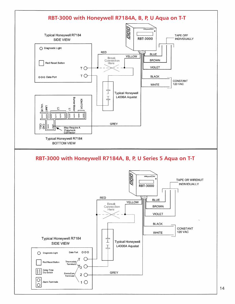
WIRING NOTE: The RBT-3000 has MULTI-VOLTAGE capability and has separate common wires for the Power and Control circuits. It is necessary that these wires be connected to the appropriate commons for the circuit or the unit will not function properly. Unused wires MUST be separately taped!
IMPROPER VOLTAGE SELECTIONS WILL DAMAGE THE UNIT and Void the Warranty.

7
RBT-3000 with Beckett Genesis Model 7505 Advanced Burner Control
RBT-3000
RBT-3000
RBT-3000 with Honeywell R7184A, B, P, U Electronic Oil Primary (T-T Jumped)

8
RBT-3000 with Carlin 40-200 or 60-200 Cad Cell RelayWhen T-Stat or Aqua-Stat is Connected To “T-T”
RB
T-30
00

9
RB
T-30
00
RB
T-30
00 w
ith
Ho
ney
wel
l L71
24A
, Co
r L7
148A
Oil
Elec
tro
nic
Aq
uas
tat
RB
T-30
00
RB
T-30
00 w
ith
Ho
ney
wel
l L71
24U
Un
iver
sal O
il El
ectr
on
ic A
qu
asta
t

10
RBT-3000
RBT-3000 with Honeywell L7148F Electronic Aquastat
RBT-3000
RBT-3000 with Honeywell L7224A, C, U or L7248A,C Oil Electronic Aquastat
11
RB
T-30
00
RB
T-30
00 w
ith
Ho
ney
wel
l L81
24A
, C
RB
T-30
00
RB
T-30
00 w
ith
Ho
ney
wel
l L81
24E
12
RB
T-30
00 w
ith
Ho
ney
wel
l L81
48E
RB
T-30
00R
BT-
3000
RB
T-30
00 w
ith
Ho
ney
wel
l L81
48 J

13
RB
T-30
00 w
ith
Ho
ney
wel
l L81
51A
RB
T-30
00R
BT-
3000
RB
T-30
00 w
ith
Ho
ney
wel
l R81
82D
14
RBT-3000
RBT-3000 with Honeywell R7184A, B, P, U Aqua on T-T
RBT-3000
RBT-3000 with Honeywell R7184A, B, P, U Series 5 Aqua on T-T

15
RB
T-30
00 w
ith
Ho
ney
wel
l R81
82E
RB
T-30
00
RB
T-30
00 w
ith
Ho
ney
wel
l R81
82F,
G
RB
T-30
00
16
RB
T-30
00
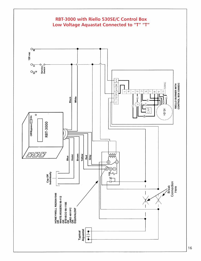
RBT-3000 with Riello 530SE/C Control BoxLow Voltage Aquastat Connected to “T” “T”

17
RB
T-30
00
RB
T-30
00 w
ith
UT
1107
-1
RB
T-30
00
RB
T-30
00 w
ith
Ho
ney
wel
l R82
85D
Fan
Cen
ter
Use
d o
n G
as B
oile
rs

18
RBT-3000 with Riello 40F5 Burner(if experiencing voltage feedback from burner on HW+”RED” Wire)
RBT-3000

19
RB
T-30
00 w
ith
Ho
ney
wel
l L81
48A
RB
T-30
00R
BT-
3000
RB
T-30
00 w
ith
Ho
ney
wel
l L81
48E,
J

Visit our Web site for the current version and more information.www.completewatersystems.com
ITT8200 N. Austin AvenueMorton Grove, IL 60053Tel: 847-966-3700Fax: 847-965-8379www.completewatersystems.com
ITT
McDonnell & Miller is a registered trademark of ITT Corporation. ITT, the Engineered Blocks Symbol are registered trademarks of ITT Manufacturing Enterprises, Inc. © 2011 MM-TB11-01 October 2011