Embed Size (px)
Citation preview

A. NSK Linear Guide™
A1〜A48
B. Ball Screws
B1〜B214
C. OtherC1〜C18

Contents
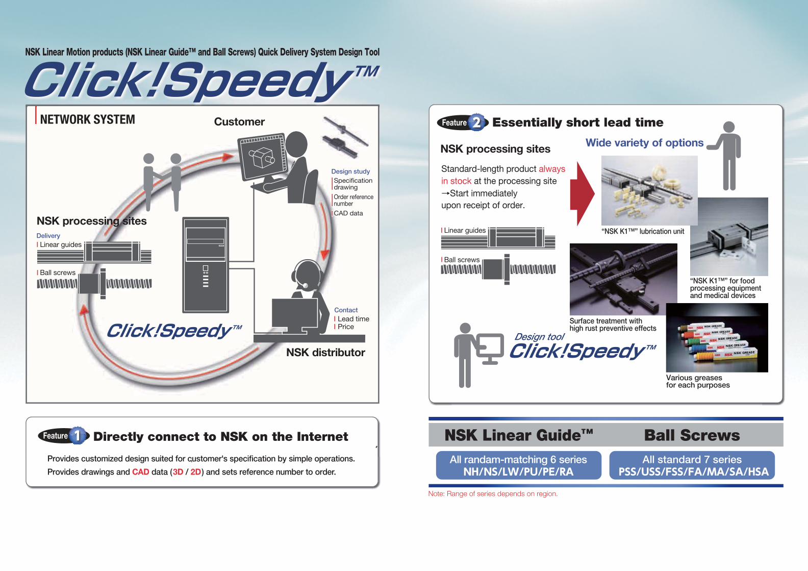
NSK Linear Guide™ Click!Speedy Series
…………………………………………… A1
A-1 Accuracy …………………………………… A5
A-2 Preload ……………………………………… A7
A-3 Materials and Surface Treatment …… A9
A-4 "NSK K1™" lubrication unit ………… A10
A-5 Lubrication ……………………………… A13
A-6 Datum surfaces ………………………… A16
A-7 Butting rail specification ……………… A17
A-8 Lubrication components ……………… A17
A-9 Mounting position and direction of
lubrication accessories ……………… A18
A-10 Dust Proof ……………………………… A19
A-11 Bolt-hole cap to plug the bolt holes
for rail mounting ……………………… A21
Dimension Table
NH15-30AN・BN …………………………… A23
NH35-65AN・BN …………………………… A25
NH25-55AL・BL …………………………… A27
NH15-30EM・GM ………………………… A29
NH35-65EM・GM ………………………… A31
NS-AL・CL …………………………………… A33
NS-EM・JM ………………………………… A35
LW17-35EL …………………………………… A37
PU09-15 ……………………………………… A39
PE09-15 ……………………………………… A41
RA25-45AN・BN …………………………… A43
RA25-45AL・BL …………………………… A45
RA25-45EM・GM ………………………… A47
Ball Screws Click!Speedy Series …………… B1
B-1 Ball screw recirculation system ……… B5
B-2 Preload system …………………………… B7
B-3 Accuracy …………………………………… B8
B-4 Friction Torque and Drive Torque … B12
B-5 Lubrication of Ball Screw …………… B14
B-6 Equipped with "NSK K1™"
Lubrication Unit ………………………… B15
B-7 Precautions When Handling Ball
Screws …………………………………… B17
B-8 Accessories ……………………………… B19
B-9 Ball screw support bearings ………… B33
Dimension Table
Compact FA PSS Type …………………… B37
Compact FA USS Type …………………… B97
Compact FA FSS Type ……………………B103
MA Type, Miniature, Fine Lead …………B119
FA Type for Small Equipment ……………B141
SA Type for Machine Tools ………………B177
HSA Type for Machine Tools ……………B197
C-1 Rust Prevention and Surface
Treatment …………………………………… C1
C-2 Clean environment ……………………… C3
C-3 Lubrication ………………………………… C6
C-4 RoHS Compliant ……………………… C18
A. NSK Linear Guide™ B. Ball Screws C. Other

A1 A2
Linear Guid
es

A3 A4
Linear Guid
es

A5 A6
PU・PE SeriesNH・NS・LW・RA Series
A-1-1 Accuracy standard The accuracy characteristics of linear guide are specified to each series in the variations of assembled height,
assembled width, and running parallelism.
A-1-2 Definition of accuracy・Table 1, Fig. 1 and Fig. 2 show accuracy characteristics.
Fig. 2 Running parallelism of slideFig. 1 Assembled dimensions
Table 1 Definition of accuracy
Characteristics Definition (Figs. 1 and 2)
Mounting height H Distance from A (rail bottom datum surface) to C (slide top surface)
Variation of H Variation of H in slides assembled to the rails of a set of linear guides
Mounting width W2 or W3 Distance from B (rail side datum surface) to D (slide side datum surface). Applicable only to the reference linear guide.
Variation of W2 or W3 Difference of the width (W2 or W3) between the assembled slides which are installed in the same rail. Applicable only to the reference linear guide.
Running parallelism of slide, surface C to surface A
Variation of C (slide top surface) to A (rail bottom datum surface) when slide is moving.
Running parallelism of slide, surface D to surface B
Variation of D (slide side datum surface) to B (rail side datum surface) when a slide is moving.
Fig. 3 Mounting width W2 Fig. 4 Mounting width W3
Mounting width: W2 and W3
・ Mounting width differs depending on the arrangement of the datum surfaces of the rail and slide on the reference
linear guide (indicated as KL on the rail). (Fig. 3 and Fig. 4)
Running parallelism of slide・ The running parallelism which matches the characteristic of each series is set for the NSK linear guides. Table 2
shows the running parallelism for each series.
A-1 Accuracy
Linear Guid
es
Table 2 Running parallelism of slide
Unit: μmUnit: μm
Accuracy gradeRail length(mm)
High precision gradePH
Normal gradePC
over or less
- 50 2 5
50 - 80 3 5
80 - 125 3 5
125 - 200 3.5 6
200 - 250 4.5 7.5
250 - 315 5 8.5
315 - 400 5.5 9.5
400 - 500 6 11
500 - 630 6.5 12
630 - 800 7 13
800 - 1 000 7.5 15
1 000 - 1 250 8.5 16
1 250 - 1 600 9.5 17
1 600 - 2 000 11 19
2 000 - 2 500 12 21
2 500 - 3 150 13 23
3 150 - 4 000 14 25
Note: LW series is only applicable to normal grade (PC)
Accuracy gradeRail length(mm)
Normal gradePC
over or less
- 50 6
50 - 80 6
80 - 125 6.5
125 - 200 7
200 - 250 8
250 - 315 9
315 - 400 11
400 - 500 12
500 - 630 14
630 - 800 16
800 - 1 000 18
1 000 - 1 250 20

A7 A8
A-1-3 Selection of accuracy・ The accuracy grade which matches the characteristic of each series is set for the NSK linear guides.
・ Table 3 shows the accuracy grades available for each series.
A-2-2 Selection of preload classification・ Several types of preload that match the characteristic of each series are set for the NSK linear guides.
・ Types of preload classification for each series are shown in Table 4. Table 5 shows the selection criterion of the
preload classification.
Fig. 6 Elastic deformation
Fig. 5 Preloading method
Table 3 Accuracy grades and applicable seriesTable 4 Classification of preload in each seriesAccuracy
gradeSeries
High precision gradePH
Normal gradePC
NH ○ ○
NS ○ ○
LW ○
PU ○
PE ○
RA ○
PreloadSeries
Medium preloadZH
Slight preloadZZ
Fine clearanceZT
NH ○ ○ ○
NS ○ ○ ○
LW ○
PU ○
PE ○
RA ○
A-2-1 Objective of preload・ An elimination of clearance between the raceways
and rolling elements vanishes the mechanical play of
the linear guide system.
・ When a preload is applied, the deformation of linear
guides by external vertical load is further improved
thus increasing the system stiffness.
・ Preloading method
The preload is applied by inserting rolling elements
slightly bigger than the space of two raceways as
shown in Fig. 5.
A-2 Preload
Combination of accuracy grade and preload・ Combinations of accuracy grade and preload are shown in Table 6.
Table 6 Combinations of accuracy grade and preload type
Table 5 Selection criterion of the preload
Classification of preload Use condition
ZTFine clearance
・ An application in which a set of two parallel linear guides (four slides/two rails) is used to sustain a unidirectional load with low vibration and impact. ・ An application in which the accuracy is not very necessary but a friction force must
be minimized.
ZZSlight preload
・ Moment loads are applied.・ Application for a highly accurate operation.
ZHMedium preload
・ Application in which extremely high stiffness is essential. ・ Application in which vibration and impact load will be applied.
Accuracy grade Preload
PH ZH, ZZ
PC ZH, ZZ, ZT*
*) NH15 to 25 and NS15 to 30 are not available.
Linear Guid
es

A9 A10
Enlarged surface of NSK K1 lubrication unit
100μm
A-3-1 Stainless steel Standard material for NSK linear guides is special high carbon steel, and stainless steel is also a standard material
for some series.
◯Stainless steel standard series
PU Series PE Series
◯Available in stainless steel
NH Series (NH15 to NH30) NS Series
Select from the above when using in the environments which invite rust.
A-3-2 Surface treatment(1) Recommended surface treatment We recommend "low temperature chrome plating" and "fluoride low temperature chrome plating" for rust prevention
because of the result of the humidity chamber test for antirust characteristics and their cost-effectiveness.
However, never apply any organic solvent to those treatments for degreasing because it has adverse effect on
antirust characteristics.
○Fluoride low temperature chrome plating・ Fluoroplastic coating is provided following the low
temperature chrome plating.
・ Resistance to corrosion is higher than electrolytic rust
prevention film treatment.
○Low temperature chrome plating (Electrolytic rust prevention black treatment)・ Used to prevent corrosion, light reflection, and for
cosmetic purpose.
(2) Rust prevention of fluoride low temperature chrome plating The use environment of NSK linear guides is expanding from general industrial machines, semiconductor and flat
panel display manufacturing systems to aerospace equipment. Among all measures to cope with environment, rust
prevention is the most challenging. Such environment includes:
・ Moisture for washing machines and other equipment
・ Chemicals used in the wet processing of semiconductor and flat panel display manufacturing equipment
NSK has developed electrolytic rust prevention black film treatment (black chrome plating) which is added by
fluororesin impregnating treatment. (Hereinafter referred as "Fluoride low temperature chrome plating") This surface
treatment methods has proved its superiority as the rust prevention of linear guides which are used in the above
equipment.
● What is "Fluoride low temperature chrome plating?" This is a type of black chrome plating which forms a black film (1 to 2 µm in thickness) on the metal surface.
Fluoroplastic coating is added to the film to increase corrosion resistance.
・ Accuracy control is easily manageable due to low temperature treatment and to the absence of hydrogen
embrittlement.
・ Product accuracy is less affected due to the thin film which has high-corrosion resistance.
・ This method is superior to other surface treatments in durability on the rolling surface.
・ Inexpensive compared with products with other surface treatment and stainless steel products.
However, do not use organic solvent because it adversely affects antirust property of the plating.
A-4-1 NSK linear guides equipped with "NSK K1™" lubrication unit NSK K1 lowers machine operation cost, and reduces
impact on the environment.
What is "long-term, maintenance-free" operation? Ball screws and linear guides which are equipped
with NSK K1 do not require maintenance for five years
or up to 10 000 km operational distance.
What is NSK K1 lubrication unit? NSK K1 is a lubrication device which combines oil
and resin in a single unit. The porous resin contains a
large amount of lubrication oil. Touching its surface to
the raceway of a rail close to the ball contact point NSK
K1 constantly supplies fresh oil which seeps from the
resin.
A-3 Materials and Surface Treatment A-4 "NSK K1™" lubrication unit
PolyolefinUnlike vinyl chloride products, polyolefin does not produce dioxin. Polyolefin
is also being used increasingly at supermarkets for food wrapping.
Lubrication oilIt is mineral oil-based lubricant. The oil has a viscosity of 100 cSt.
Remarkable capacity with new material: NSK K1™ lubrication unit information
● A NSK K1 lubrication unit (referred to as NSK K1
hereafter) equipped with an NSK linear guide is an
outstanding new lubrication material.
● A Newly developed porous synthetic resin contains
large volume of lubricant oil that seeps out and
enhances lubricating function.
● Simply install NSK K1 inside a standard end seal
(rubber).
Fig. 7
Linear Guid
es

(2) Available models Table 7 shows available models.
Table 7 Available models
Series Size
NH NH15, NH20, NH25, NH30
NS NS15, NS20, NS25, NS30
LW LW17, LW21, LW27
PU PU09, PU12, PU15
PE PE09, PE12, PE15
Precautions for use
To maintain optimal performance of NSK K1 lubrication unit over a long time, please follow the instructions below:
1.Temperatures range for use: Maximum temperature in use: 50°C Momentary maximum temperature in use: 80°C
2.Chemicals that should not come to contact : Do not leave NSK K1 lubrication unit in organic
solvent, white kerosene such as hexane, thinner which removes oil, and rust prevention oil which contains white kerosene.
Note: Water-type cutting oil, oil-type cutting oil and grease such as mineral-type and ester-type do not damage NSK K1 lubrication unit.
A11 A12
Linear Guid
es
A-4-2 Specifications(1) Applicable series ・ Can be installed in each series.
・ Can be used with stainless steel materials and surface-treated items.
(2) Standard specifications ・ NSK K1 is installed between the end seal and end cap. (Double seals, protectors, etc. are available for some series.)
・ NSK standard grease is packed inside the slide. (Users can select from NSK standard grease.)
・ Accuracy and preload classifications are the same as standard items. (Dynamic friction increases slightly due to
NSK K1.)
(3) Number of installed NSK K1 Normally, one NSK K1 should be installed on both ends of slides. (two K1s for one slide)
If NSK K1 is required depending on service conditions and environment, a maximum of two sheets per side (four
sheets on both sides) can be added. If even more sheets than these is necessary, please consult NSK.
A-4-3 "NSK linear guides for food processing equipment and medical devices" for sanitary environment
Used with NSK K1 for food processing equipment and medical devices and grease for food processing equipment.
What is "NSK K1™" for food processing equipment and medical devices? With an amazing innovation lubrication unit, the NSK K1 for food processing equipment and medical devices
utilizing the US Food and Drug Administration (FDA) compliant material, provides reliability when used in food
processing equipment and medical devices. The newly developed porous synthetic resin contains abundant
lubricant. With the basic function of highly praised NSK K1 lubrication unit for general industry, more sophisticated
materials make it applicable in food and medical equipment.
It also offers easy installation: it is installed inside the standard end seal.
(1) Features The highest grade of category H1 grease of USDA standard is used for NSK K1 lubrication unit.
*category H1: Lubricants permitted for use where there is possibility of incidental food contact
*USDA: USDA (The United States Department of Agriculture)
<Features of grease for food processing machines>
・ This grease is approved by USDA H1. (National Science Foundation [NSF] carries out certification for USDA.)
・ Superb water resistance and antirust capability
・ Superb wear resistance
・ Applicable for a centralized oiling system
Mainly there are two ways of lubrication, grease and oil, for linear guides. Use a lubricant agent and method most
suitable to condition requirements and the purpose to optimize functions of linear guides.
In general, lubricants with low base oil kinematic viscosity are used for high-speed operation, in which thermal
expansion has a large impact, and in low temperatures.
Lubrication with high base oil kinematic viscosity is used for oscillating operations, operations in low speeds and in
high temperatures.
The following are lubrication methods by grease and by oil.
A-5-1 Grease Lubrication Grease lubrication is widely used because it does not require a special oil supply system or piping. Grease
lubriction accessories available from NSK are:
・ Various types of grease in bellows tube which can be instantly attached to the hand grease pump;
・ NSK Grease Unit that consists of a hand grease pump and various nozzles. These are compact and easy to use.
(1) NSK grease lubricants Table 8 shows the marketed general grease widely used for linear guides. In addition to these grease, NSK
provides special grease for specific conditions and purposes.
(2) How to replenish grease Use the grease fitting of a slide if an exclusive grease supply system is not used. Supply the required amount of
grease by a grease pump. Wipe off old grease and accumulated dust before supplying new grease. If the grease
fitting is not used due to the size limitation, apply grease directly to the rail. Remove the seal if possible, and move
the slide few strokes so the grease permeates it. A hand grease pump, an exclusive and easy lubricating device for
linear guides, is available at NSK.
(3) Volume of grease to be replenished Once grease is replenished, another supply is not required for a long time. But under some operational conditions,
it is necessary to periodically replenish grease. The following are replenishing methods.
・ When there is an exclusive grease supply system and the volume from the spout can be controlled, the criterion is:
All at once, replenish the amount that fills about 50% of the internal space of the slide. This method eliminates
waste of grease, and is efficient. Page C11 shows the internal spaces of slide of each series for your reference.
・ When replenishing grease using a grease pump:
Use a grease pump and fill the inside of slide with grease. Supply grease until it comes out from the slide
area. Move the slide by hand while filling them with grease, so the grease permeates all areas. Do not operate
the machine immediately after replenishing. Always try to run-in the system a few times to spread the grease
throughout the system and to remove excess grease from inside. Running-in operation is necessary because the
sliding force of the linear guide greatly increases immediately after the replenishment (full-pack state) and may
cause problems. Grease's stirring resistance is accountable for this phenomenon. Wipe off excess grease that
accumulates at the end of the rail after trial runs, so the grease does not scatter to other areas.
(4) Intervals of checks and replenishments Although the grease is of high quality, it gradually deteriorates and its lubrication function diminishes. Also, the
grease in the slide is gradually removed by stroke movement. In some environments, the grease becomes dirty, and
foreign objects may enter a slide. New grease should be replenished depending on the frequency of use. Table 9
shows a guide of intervals of grease replenishments to linear guides.
Table 9 Intervals of checks and replenishments for grease lubrication
Intervals of checks Items to be checked Intervals of replenishments
3- 6 monthsDirt, foreign matters such
as cutting chip
Usually once per year is sufficient. Every 3 000 km for a system such as material handling equipment that travels more than 3 000 km per year. Replenish if checking results warrant it necessary.
A-5 Lubrication
Table 8 Grease lubricant for linear guides
Type Thickener Base oilBase oil kinematic
viscositymm2/s (40°C)
Range of usetemperature (°C) Purpose
AS2*1 Lithium type Mineral oil 130 -10 to 110For general use at high load
PS2*2 Lithium typeSynthetic oil + synthetic
hydrocarbon oil15.9 -50 to 110
For low temperature and high frequency operation
LG2 Lithium typeMineral oil+ synthetic
hydrocarbon oil32 -20 to 70 For clean environment
LGU DiureaSynthetic
hydrocarbon oil95.8 -30 to 120 For clean environment
NF2Urea composite
typeSynthetic
hydrocarbon oil26 -40 to 100 For fretting resistant
PARALIQGA351*3
Aluminium complex
Paraffin oil ー -40 to 120For food processing machine
*1) Standard grease of NH, NS, LW, and RA Series.*2) Standard grease of PU and PE Series.*3) NSF H1 registered grease.
Notes: 1) As a general rule, do not mix greases of different brands. Grease structure may be destroyed if greases of different thickeners are mixed. Even when greases have the same thickener, different additives in them may have an adverse effect on each other.
2) Grease viscosity varies by temperature. Viscosity is particular high in winter due to low temperature. Pay attention to increase in linear guide's sliding resistance in such occasion.
A13 A14
Linear Guid
es

A-5-2 Oil lubrication Required amount of new oil is regularly supplied by:
・ Manual or automatic intermittent supply system;
・ Oil mist lubricating system via piping.
Equipment for oil lubrication is more costly than one for grease lubrication. However, oil mist lubricating system
supplies air as well as oil, thus raising the inner pressure of the slide. This prevents foreign matters from entering,
and the air cools the system. Use an oil of high atomizing rate such as ISO VG 32-68 for the oil mist lubrication
system.
ISO VG 68-220 are recommended for common intermittent replenishment system. Approximate volume of oil Q for
a slide of linear guide per hour can be obtained by the following formula.
In case of all ball type linear guides
Q ≥ n / 150(cm3/hr) In case of RA series
Q ≥ n / 100(cm3/hr) n: Linear guide size code
e.g. When NH45 is used, n= 45
Therefore, Q= 45/150= 0.3 cm3/hr
For the oil lubrication by gravity drip, the oil supply position and installation position of the slide are crucial. In case
of linear guide, unless it is installed to a horizontal position, the oil flows only on the down side, and does not spread
to all raceway surface. This may cause insufficient lubrication. Please consult NSK to correct such situations prior to
use. NSK has the internal design which allows oil lubricant to flow throughout the system.
Table 10 shows the criterion of intervals of oil checks and replenishments.
Table 10 Intervals of checks and replenishments
Method Intervals of checks Items to check Replenishment or intervals of changes
Automatic intermittent supply
WeeklyVolume of oil,
dirt, etc.Replenish at each check.
Suitable volume for tank capacity.
Oil bathDaily before operation
Oil surfaceMake a suitable criterion based
on consumption
Notes: 1) As with grease lubrication, do not mix oil lubricant with different types. 2) Some components of the linear guide are made of plastic. Avoid using an oil that adversely affects synthetic resin. 3) When using oil mist lubricating system, please confirm an oil supply amount at the each outlet port.
・ For NSK linear guides, the datum surfaces of the
rail and of the slide are either marked with a "datum
surface groove" or with an "arrow." (Fig. 8).
・ When the datum surfaces of the reference side rail
and slides are pressed to their mounting datum
surfaces respectively, the variation of distance
(mounting width W2 or W3) between the datum
surfaces of the rails and that of the slides must
be a minimum and therefore, it is specified as the
standard. (Figs. 9 and 10)
・ The ways to indicate the datum surfaces of each
series are shown in Table 11.
Fig. 9 Most common setting of the referenc side rail
Fig. 10 Setting of the reference side rail in certain occasionsFig. 8 Datum surface
A-6 Datum Surfaces
Model No.Material
Standard PU series NH15, NS15PE seriesLW17, 21
Special high carbon steel
Stainless steel
Table 11 Marks on the rail datum surfaces in each series
A15 A16
Linear Guid
es

・ A rail which requires the length that exceeds the
machine capacity manufactured maximum length
comes in butting specification.
・ The rails with butting specification are marked with
an arrow on the opposite side of the mounting datum
surface. Use the arrows for assembly order and
direction of the rail (Fig. 11).
・ The pitch of the rail mounting hole on the butting
section should be as F in Fig. 12. When two rails are
used in parallel, the butted sections should not align.
This is to avoid change in the running accuracy of the
table at the butted sections.
・ We recommend shifting the butting sections more
than the length of a slide. If the higher running
accuracy is required, consider installing the slides
into the table so that they do not simultaneously pass
the butting sections.
Fig. 11
Fig. 12
Fig. 13 Grease fitting and tube fitting
A-7 Butting rail specification
1. Types of lubrication accessories Fig. 13 show grease fittings and tube fittings.
We provide lubrication accessories with extended
thread body length (L) for the addition of dust-proof
accessories such as NSK K1 lubrication unit, double
seal and protector.
We provide a suitable lubrication accessory for the
special requirement on dust-proof accessories.
Consult NSK for a lubrication accessory with
extended length of thread body for your convenience of
replenishing lubricant.
When you require stainless lubrication accessories,
please ask NSK.
A-8 Lubrication components
When the lubrication accessory is chosen, not only its standard position but also the other position can be
selected on each slide. The right or left end as seen from the datum surface of slide can be selected.
Furthermore, for B or C type grease fitting and LF type tube fitting, the direction of the lubrication port can be
selected. “The datum surface direction” facing the datum surface side, or “upward” facing the top surface of the
slide as well as standard “the opposite direction of the datum surface” facing the opposite direction of the datum
surface can be selected. The directions of each lubrication port should be the same for all slides on one rail.
Table 12 shows positions and directions of each case.
A-9 Position and direction of lubrication accessory
Direction (symbols in the table represent positions and directions of lubrication accessory in case of slide only)
Opposite direction of the datum surface Datum surface direction Upward
Mounting position
Seeing from the datum
surface
Right end
Code: A Code: C Code: E
Left end
Code: B Code: D Code: F
Without lubrication accessory
Code: N
Note) When drive-in type fitting (φ3) is chosen, use code A or B is also used for positions of lubrication accessory in case of slide only.
Attention) Depending on a direction of lubrication accessory, some problems could be caused such as interference with the table mounting to the slide top surface (especially upward) or tightening of piping connected to the lubrication accessory. Please check space around the lubrication accessory on the drawing beforehand.
Datum surface
Datum surface
2-Plug
Datum surface
Datum surface
Datum surface
Datum surface
Table 12 Positions and directions of lubrication accessories
A17 A18
Linear Guid
es

A-10-1 Standard specification parts・ To keep foreign matters from entering inside the slide,
NSK linear guides have end seals on both ends,
bottom seals at the bottom surfaces, and an inner
seal in the inside of slide.
・ The seals for standard specification for each series
are shown in Table 13.
A-10 Dust Proof
Table 13 Standard seals
Series End seal Bottom seal Inner seal
NH ○ ○ -
NS ○ ○ -
LW ○ ○ -
PU ○ - -
PE ○ - -
RA ○ ○ ○
○: Equipped as a standard feature
Fig. 14
A-10-2 Dust-proof parts・ NSK has the following items for the dust-proof parts. Select a suitable type for the operating environment.
(1) Double seal・ It is a combination of two end seals to enhance seal
function.
・ When the double seal is installed, the end seal
section becomes thicker than the standard item.
Please pay attention to the increase in a slide length
when designing the mounting dimension of slide
and the table stroke. Please refer to each series
dimension for length of the slide with double seal
installed.
(2) Protector・ A protector is usually installed outside the end seal
to prevent high-temperature fine particles such as
welding spatter and other hard foreign matters from
entering the slide.
・ Same as the case with the double seal, when the
protector is installed, the slide becomes longer.
Take this thickness of slide into consideration for
determining the relevant dimensions such as the
system stroke and the slide installation envelope.
Please refer to each series dimension table for length
of the slide with protector installed.
Table 14 Optional dust-proof parts
Name Purpose
NSK K1 lubrication unit Made of oil impregnated resin. Enhances lubricating functions. Refer to page A10.
Double seal It combines two end seals for enhancing sealing function.
Protector Protect the end seal from hot and hard contaminants.
Rail capPrevents foreign matters, such as swarf generated in cutting operation from clogging the rail-mounting holes. Refer to page A22.
Fig. 15 Double seal
Fig. 16 Protector
A19 A20
Linear Guid
es

・ After the rail is mounted to the machine base, a bolt-
hole cap is used to plug the bolt hole to prevent
foreign matters from clogging up the hole and from
entering into the slide (Fig. 17).
・ The bolt-hole cap is made of synthetic resin which
has superb in its resistance to oil and abrasion.
・ To insert the cap into the rail bolt hole, use a flat
dolly block (Fig. 18). Pound the cap gradually until its
height becomes flush with the rail top surface.
A-11 Bolt-hole cap to plug the bolt holes for rail mounting
Fig. 17
Fig. 18
A21 A22
Linear Guid
es

Side view of AN and BN types
Front view of AN and BN types
Table 1 Dimensions
Model No.Slide shape
Assembly Ball slideHeight
H E W2
Width
W
Length
L
Mounting hole
L1 K T
Grease fitting
B J M×pitch×ℓ Hole size T1 NNH15AN AN 28 4.6 9.5 34 55 26 26 M4×0.7×6 39 23.4 8 φ3 8.5 3.3NH15BN BN 74 58NH20AN AN 30 5 12 44 69.8 32 36 M5×0.8×6 50 25 12 M6×0.75 5 11NH20BN BN 91.8 50 72NH25AN AN 40 7 12.5 48 79 35 35 M6×1×9 58 33 12 M6×0.75 10 11NH25BN BN 107 50 86NH30AN AN 45 9 16 60 85.6 40 40 M8×1.25×10 59 36 14 M6×0.75 10 11NH30BN BN 124.6 60 98
Model No.
Rail Basic load rating WeightWidth
W1
Height
H1
Pitch
F
Mountingbolt holed×D×h
G
(reference)
Max. lengthL0max
( ) for stainless
*)Dynamic Static Static moment (N·m) Ball slide Rail[50km]C50 (N)
[100km]C100 (N)
C0(N)
MRO MPO MYO(kg) (kg/m)(One slide) (Two slides) (One slide) (Two slides)
NH15AN 15 15 60 4.5×7.5×5.3 20 2 980(1 800)
14 200 11 300 20 700 108 94.5 575 79.5 480 0.18 1.6NH15BN 18 100 14 400 32 000 166 216 1 150 181 965 0.26NH20AN
20 18 60 6×9.5×8.5 20 3 960(3 500)
23 700 18 800 32 500 219 185 1 140 155 955 0.33 2.6
NH20BN 30 000 24 000 50 500 340 420 2 230 355 1 870 0.48NH25AN 23 22 60 7×11×9 20 3 960
(3 500)33 500 26 800 46 000 360 320 1 840 267 1 540 0.55 3.6
NH25BN 45 500 36 500 71 000 555 725 3 700 610 3 100 0.82NH30AN 28 26 80 9×14×12 20 4 000
(3 500)41 000 32 500 51 500 490 350 2 290 292 1 920 0.77 5.2
NH30BN 61 000 48 500 91 500 870 1 030 5 600 865 4 700 1.3
Unit: mm
Notes: External appearance of stainless steel ball slides differs from those of special carbon steel ball slides. *) The basic load rating comply with the ISO standard. (ISO 14728-1, 14728-2)
C50 ; the basic dynamic load rating for 50 km rated fatigue life C100 ; the basic dynamic load rating for 100 km rated fatigue life The basic static load rating shows static permissible load.
Fig. 2 "NSK K1™" lubrication unit
Fig. 1 Front view and side view
Grease fitting
Tube fitting
Fig. 3 Grease fitting and tube fittingStandard lubrication accessory for NH15 is drive-in type (φ3). Standard lubrication accessory for NH20 or over is B type.
Fine clearanceZT
Slight preloadZZ
Medium preloadZH
Preload code T Z H
Model No.
NH15 - –4 to 0 –7 to –3NH20 - –5 to 0 –8 to –3NH25 - –5 to 0 –9 to –4NH30 –5 to 15 –7 to 0 –12 to –5
Table 6 Preload code and amount of clearance/preload Unit: μm
Notes 1) Medium preload is available for special high-carbon steel products. 2) Minus sign denotes that a value is an amount of preload (elastic deformation of balls).
Table 3 Accuracy grade and accuracy standardTable 2 Material/surface treatment code Unit: µm
Accuracy gradeHigh precision
gradeNormal grade
"NSK K1™" lubrication unit
Without NSK K1 lubrication unit PH PCWith NSK K1 lubrication unit KH KC
With NSK K1 for food and medical equipment FH FC
Characteristics
Mounting height H ±20 ±20Variation of H 15①
30②15①30②
Mounting width W2 or W3 ±30 ±30Variation of W2 or W3 20 25
Running parallelism of surface C to surface ASee page A6. See page A6.Running parallelism of surface D to surface B
Notes 1) High precision grade is available for special high-carbon steel products. 2) ①: Variation on the same rail ②: Variation on multiple rails 3) "NSK K1™" lubrication unit: Equipped with NSK linear guide. A Newly developed porous synthetic
resin contains large volume of lubricant oil that seeps out and enhances lubricating function.
Notes: Low temperature chrome plating: Electrolytic rust prevention black treatment (black chrome plating) Fluoride low temperature chrome plating: Fluoroplastic coating is provided following the low temperature chrome plating.
TypeSpecial high carbon steel
Stainless steel
Without surface treatment N K
Low temperature chrome plating D H
Fluoride low temperature chrome plating F E
Table 4 Dust-proof specification code and length of ball slide equipped with dust-proof components Unit: mm
Notes: Double seal: It combines two end seals for enhancing sealing function. Protector: Protect the end seal from hot and hard contaminants. Rail cap: Prevents foreign matters, such as swarf generated in cutting operation from clogging the rail-mounting holes.
Dust-proof specification StandardDouble seal
installedProtector installed
Double sealand protector
installed
Increase when NSK K1 installed
Dust-proof code
Rail cap Without A C E GWith B D F H
Ball slide length
Model No.
NH15AN 55 - - - +10.6NH15BN 74 - - -NH20AN 69.8 74.8 75.6 80.6 +10.6NH20BN 91.8 96.8 97.6 102.6NH25AN 79 84.6 85.4 91 +11.6NH25BN 107 112.6 113.4 119NH30AN 85.6 92.8 94 101.2 +12.0NH30BN 124.6 131.8 133 140.2
Table 5 Packed lubricantType Code Thickener Base oil
Base oil kinematic viscosity
[mm2/s (40 C)]
Range of usetemperature ( C) Purpose
AS2 1 Lithium type Mineral oil 130 –10 to 110 For general use at high load
PS2 2 Lithium typeSynthetic oil +
synthetic hydrocarbon oil 15.9 –50 to 110For low temperature and high frequency operation
LR3 3 Lithium type Synthetic oil 30 –30 to 130 For high speed, medium load
LG2 4 Lithium typeMineral oil + synthetic
hydrocarbon oil 32 –20 to 70 For clean environment
LGU 5 Diurea Synthetic hydrocarbon oil 95.8 –30 to 120 For clean environment
NF2 6 Urea composite type Synthetic hydrocarbon oil 26 –40 to 100 For fretting resistant
PARALIQ GA351 7 Aluminium complex Paraffin oil - –40 to 120 For food processing equipmentNone (Rust
preventive oil applied) 9 - - - - -
Reference number
(*1) The design serial number is not required when the mounting width is W2, dimensions of G at right and left ends of the rail are the same and minimum, the rail isn't with butting, the selected lubrication accessory is not only the standard type (drive-in type / B type) but also mounted standard position and direction, and the codes of packed lubricant, dust-proof specification and rail mounting hole specification are prepared.
(*2) The design serial number should be given when the requirements are not satisfied.(*3) The design serial number is not required when the selected lubrication accessory is not only the standard type (drive-in type / B type) but also mounted
standard position and direction and the codes of packed lubricant, dust-proof specification and rail mounting hole specification are standard.(*4) The design serial number is not required when the dimension of G at left end on the drawing is two or less digit integer. If dimension of G at left end is
decimal fraction number, G at right end must be equivalent to the left end G dimension, otherwise design serial number will be necessary. And if butting rail is required, design serial number will be necessary.
Without serial number (*1)Series name
Size
Rail length (mm)
Number of ball slides per rail
Ball slide shape code (See Table 1.)
Material/surface treatment code (See Table 2.)
Dust-proof code (See Table 4.)
Packed lubricant code (See Table 5.)
Accuracy code (See Table 3.)
Rail mounting hole codeL: Standard
Preload code (See Table 6.)
Rail and ball slide assemblyPC Z 1 A L30 N 21200 ANNH
With serial number (*2)Design serial number
Ex.) 001, 002, 003, ..., 010, 011, ...+01, +02, +03, ..., +10, +11, ...
Size
Rail length (mm)
Rail series codeN1H: NH Series rail
Rail shape code: LL: Standard
Material/surface treatment code (See Table 2.)
Dimension GIndicated in two digit after “=” (equal)
Accuracy code (See Table 3.)
Preload code (See Table 6.)
Butting rail specificationN: Non-butting. L: Butting specification
Without serial number (*4)Rail
1200 PC Z = 4030 NNLN1H
Design serial numberEx.) 001, 002, 003, ..., 010, 011, ...
+01, +02, +03, ..., +10, +11, ...
With serial number (*2) ***1200 PC Z30 NNLN1H
With serial number (*2)Design serial number
Ex.) 001, 002, 003, ..., 010, 011, ...+01, +02, +03, ..., +10, +11, ...
Without serial number (*3)
Size
Ball slide series codeNAH: NH Series ball slide
Accuracy code (See Table 3.)
Ball slide shape code (See Table 1.)
Material/surface treatment code (See Table 2.)
Lubrication accessories position and direction code
A, B, C, D, E, F, N (See A18)
Preload code (See Table 6.)
Dust-proof code (See Table 4.)Packed lubricant code (See Table 5.)
Ball slidePC Z 1 A A30 NANNAH
PC Z30 N 21200 ANNH ***
PC Z30 NANNAH ***
NH Series(NH15 to 30) NH‒AN, NH‒BN/ Cross-sections:Square (High type)
A23
NH Series
A24
Linear Guid
esN
H S
eries
Model No.Slide shape
Assembly Ball slideHeight
H E W2
Width
W
Length
L
Mounting hole
L1 K T
Grease fitting
B J M×pitch×ℓ Hole size T1 NNH35AN AN
55 9.5 18 70109
5050
M8×1.25×1280
45.5 15 M6×0.75 15 11NH35BN BN 143 72 114NH45AN AN
70 14 20.5 86139
6060
M10×1.5×17105
56 17 Rc1/8 20 13NH45BN BN 171 80 137NH55AN AN
80 15 23.5 100163
7575
M12×1.75×18126
65 18 Rc1/8 21 13NH55BN BN 201 95 164NH65AN AN
90 16 31.5 126193
7670
M16×2×20147
74 23 Rc1/8 19 13NH65BN BN 253 120 207
Model No.
Rail Basic load rating WeightWidth
W1
Height
H1
Pitch
F
Mountingbolt holed×D×h
G
(reference)
Max. length
L0max
*)Dynamic Static Static moment (N·m) Ball slide Rail[50km]C50(N)
[100km]C100(N)
C0(N)
MRO MPO MYO(kg) (kg/m)(One slide) (Two slides) (One slide) (Two slides)
NH35AN 34 29 80 9×14×12 20 4 00062 500 49 500 80 500 950 755 4 500 630 3 800 1.5
7.2NH35BN 81 000 64 500 117 000 1 380 1 530 8 350 1 280 7 000 2.1NH45AN
45 38 105 14×20×17 22.5 3 990107 000 84 500 140 000 2 140 1 740 9 750 1 460 8 150 3.0
12.3NH45BN 131 000 104 000 187 000 2 860 3 000 15 600 2 520 13 100 3.9NH55AN 53 44 120 16×23×20 30 3 960
158 000 125 000 198 000 3 600 3 000 16 300 2 510 13 700 4.716.9
NH55BN 193 000 153 000 264 000 4 850 5 150 26 300 4 350 22 100 6.1NH65AN 63 53 150 18×26×22 35 3 900
239 000 190 000 281 000 6 150 4 950 27 900 4 150 23 400 7.724.3
NH65BN 310 000 246 000 410 000 8 950 10 100 51 500 8 450 43 500 10.8
Fig. 1 Front view and side view
Reference number
Without serial number (*1)Series name
Size
Rail length (mm)
Number of ball slides per rail
Ball slide shape code (See Table 1.)
Material/surface treatment code (See Table 2.)
Dust-proof code (See Table 4.)
Packed lubricant code (See Table 5.)
Accuracy code (See Table 3.)
Rail mounting hole codeL: Standard
Preload code (See Table 6.)
Rail and ball slide assemblyPC Z 1 A L45 N 21300 ANNH
With serial number (*2)Design serial number
Ex.) 001, 002, 003, ..., 010, 011, ...+01, +02, +03, ..., +10, +11, ...
Size
Rail length (mm)
Rail series codeN1H: NH Series rail
Rail shape code: LL: Standard
Material/surface treatment code (See Table 2.)
Dimension GIndicated in two digit after “=” (equal)
Accuracy code (See Table 3.)
Preload code (See Table 6.)
Butting rail specificationN: Non-butting. L: Butting specification
Without serial number (*4)Rail
1300 PC Z = 2045 NNLN1H
Design serial numberEx.) 001, 002, 003, ..., 010, 011, ...
+01, +02, +03, ..., +10, +11, ...
With serial number (*2) ***1300 PC Z45 NNLN1H
Without serial number (*3)
Size
Ball slide series codeNAH: NH Series ball slide
Accuracy code (See Table 3.)
Ball slide shape code (See Table 1.)
Material/surface treatment code (See Table 2.)
Lubrication accessories position and direction code
A, B, C, D, E, F, N (See A18)
Preload code (See Table 6.)
Dust-proof code (See Table 4.)Packed lubricant code (See Table 5.)
Ball slidePC Z 1 A A45 NANNAH
PC Z45 N 21300 ANNH ***
With serial number (*2)Design serial number
Ex.) 001, 002, 003, ..., 010, 011, ...+01, +02, +03, ..., +10, +11, ...
PC Z45 NANNAH ***
NH Series(NH35 to 65) NH‒AN, NH‒BN/ Cross-sections:Square (High type) Table 1 Dimensions Unit: mm
*) The basic load rating comply with the ISO standard. (ISO 14728-1, 14728-2) C50 ; the basic dynamic load rating for 50 km rated fatigue life C100 ; the basic dynamic load rating for 100 km rated fatigue lifeThe basic static load rating shows static permissible load.
Fig. 2 "NSK K1™" lubrication unit
Grease fitting
Tube fitting
Fig. 3 Grease fitting and tube fittingStandard lubrication accessory is B type
Accuracy gradeHigh precision grade Normal grade NH35 NH45, 55, 65 NH35 NH45, 55, 65
"NSK K1™" lubrication
unit
Without NSK K1 lubrication unit PH PC
With NSK K1 lubrication unit KH KC
Characteristics
Mounting height H ±20 ±30 ±20 ±30Variation of H 15①
30②20①35②
15①30②
20①35②
Mounting width W2 or W3 ±30 ±35 ±30 ±35Variation of W2 or W3 20 20 25 30
Running parallelism of surface C to surface ASee page A6. See page A6.
Running parallelism of surface D to surface B
Table 3 Accuracy grade and accuracy standardTable 2 Material/surface treatment code Unit: μm
Notes 1) ①: Variation on the same rail ②: Variation on multiple rails 2) "NSK K1™" lubrication unit: Equipped with NSK linear guide. A Newly developed porous synthetic resin
contains large volume of lubricant oil that seeps out and enhances lubricating function.
Notes: Low temperature chrome plating: Electrolytic rust prevention black treatment (black chrome plating) Fluoride low temperature chrome plating: Fluoroplastic coating is provided following the low temperature chrome plating.
TypeSpecial high carbon steel
Without surface treatment N
Low temperature chrome plating D
Fluoride low temperature chrome plating F
Table 5 Packed lubricantType Code Thickener Base oil
Base oil kinematic viscosity
[mm2/s (40 C)]
Range of usetemperature (°C) Purpose
AS2 1 Lithium type Mineral oil 130 –10 to 110 For general use at high load
PS2 2 Lithium typeSynthetic oil + synthetic
hydrocarbon oil 15.9 –50 to 110For low temperature and high frequency operation
LR3 3 Lithium type Synthetic oil 30 –30 to 130 For high speed, medium load
LG2 4 Lithium typeMineral oil + synthetic
hydrocarbon oil 32 –20 to 70 For clean environment
LGU 5 Diurea Synthetic hydrocarbon oil 95.8 –30 to 120 For clean environment
NF2 6 Urea composite type Synthetic hydrocarbon oil 26 –40 to 100 For fretting resistant
PARALIQ GA351 7 Aluminium complex Paraffin oil - –40 to 120 For food processing equipment
None (Rust preventive oil applied) 9 - - - - -
Table 4 Dust-proof specification code and length of ball slide equipped with dust-proof components Unit: mm
Notes: Double seal: It combines two end seals for enhancing sealing function. Protector: Protect the end seal from hot and hard contaminants. Rail cap: Prevents foreign matters, such as swarf generated in cutting operation from clogging the rail-mounting holes.
Dust-proof specification StandardDouble seal
installedProtector installed
Double sealand protector
installed
Increase when NSK K1 installed
Dust-proof code
Rail cap Without A C E GWith B D F H
Ball slide length
Model No.
NH35AN 109 116.2 117.4 124.6+13
NH35BN 143 150.2 151.4 158.6NH45AN 139 147.6 148.8 157.4
+15NH45BN 171 179.6 180.8 189.4NH55AN 163 171.6 172.8 181.4
+15NH55BN 201 209.6 210.8 219.4NH65AN 193 202.8 204 213.8
+18NH65BN 253 262.8 264 273.8
Table 6 Preload code and amount of clearance/preload Unit: μm
Fine clearanceZT
Slight preloadZZ
Medium preloadZH
Preload code T Z H
Model No.
NH35 –5 to 15 –7 to 0 –12 to –5NH45 –5 to 15 –7 to 0 –14 to –7NH55 - –9 to 0 -NH65 - –9 to 0 -
Note: Minus sign denotes that a value is an amount of preload (elastic deformation of balls).
Side view of AN and BN types
Front view of AN and BN types
(*1) The design serial number is not required when the mounting width is W2, dimensions of G at right and left ends of the rail are the same and minimum, the rail isn't with butting, the selected lubrication accessory is not only the standard type (B type) but also mounted standard position and direction, and the codes of packed lubricant, dust-proof specification and rail mounting hole specification are prepared.
(*2) The design serial number should be given when the requirements are not satisfied.(*3) The design serial number is not required when the selected lubrication accessory is not only the standard type (B type) but also mounted standard position
and direction and the codes of packed lubricant, dust-proof specification and rail mounting hole specification are standard.(*4) The design serial number is not required when the dimension of G at left end on the drawing is two or less digit integer. If dimension of G at left end is
decimal fraction number, G at right end must be equivalent to the left end G dimension, otherwise design serial number will be necessary. And if butting rail is required, design serial number will be necessary.
A25
NH Series
A26
Linear Guid
esN
H S
eries

Side view of AL and BL types
Front view of AL and BL types
Fig. 1 Front view and side view
NH Series(NH25 to 55) NH‒AL, NH‒BL / Cross-sections:Square (Low type)
Grease fitting
Table 1 Dimensions Unit: mm
Model No.Slide shape
Assembly Ball slideHeight
H E W2
Width
W
Length
L
Mounting hole
L1 K T
Grease fitting
B J M×pitch×ℓ Hole size T1 NNH25AL AL 36 7 12.5 48 79 35 35 M6×1×6 58 29 12 M6×0.75 6 11NH25BL BL 107 50 86NH30AL AL 42 9 16 60 85.6 40 40 M8×1.25×8 59 33 14 M6×0.75 7 11NH30BL BL 124.6 60 98NH35AL AL 48 9.5 18 70 109 50 50 M8×1.25×8 80 38.5 15 M6×0.75 8 11NH35BL BL 143 72 114NH45AL AL 60 14 20.5 86 139 60 60 M10×1.5×10 105 46 17 Rc1/8 10 13NH45BL BL 171 80 137NH55AL AL 70 15 23.5 100 163 75 75 M12×1.75×13 126 55 15 Rc1/8 11 13NH55BL BL 201 95 164
Model No.
Rail Basic load rating WeightWidth
W1
Height
H1
Pitch
F
Mountingbolt holed×D×h
G
(reference)
Max. length
L0max
*) Dynamic Static Static moment (N·m) Ball slide Rail[50km]C50 (N)
[100km]C100 (N)
C0(N)
MRO MPO MYO(kg) (kg/m)(One slide) (Two slides) (One slide) (Two slides)
NH25AL 23 22 60 7×11×9 20 3 960 33 500 26 800 46 000 360 320 1 840 267 1 540 0.46 3.6NH25BL 45 500 36 500 71 000 555 725 3 700 610 3 100 0.69NH30AL 28 26 80 9×14×12 20 4 000 41 000 32 500 51 500 490 350 2 290 292 1 920 0.69 5.2NH30BL 61 000 48 500 91 500 870 1 030 5 600 865 4 700 1.16NH35AL 34 29 80 9×14×12 20 4 000 62 500 49 500 80 500 950 755 4 500 630 3 800 1.2 7.2NH35BL 81 000 64 500 117 000 1 380 1 530 8 350 1 280 7 000 1.7NH45AL 45 38 105 14×20×17 22.5 3 990 107 000 84 500 140 000 2 140 1 740 9 750 1 460 8 150 2.2 12.3NH45BL 131 000 104 000 187 000 2 860 3 000 15 600 2 520 13 100 2.9NH55AL 53 44 120 16×23×20 30 3 960 158 000 125 000 198 000 3 600 3 000 16 300 2 510 13 700 3.7 16.9NH55BL 193 000 153 000 264 000 4 850 5 150 26 300 4 350 22 100 4.7
*) The basic load rating comply with the ISO standard. (ISO 14728-1, 14728-2) C50 ; the basic dynamic load rating for 50 km rated fatigue life C100 ; the basic dynamic load rating for 100 km rated fatigue lifeThe basic static load rating shows static permissible load.
Fig. 2 "NSK K1™" lubrication unit
Tube fitting
Fig. 3 Grease fitting and tube fittingStandard lubrication accessory is B type.
Table 5 Packed lubricantType Code Thickener Base oil
Base oil kinematic viscosity
[mm2/s (40 C)]
Range of usetemperature (°C) Purpose
AS2 1 Lithium type Mineral oil 130 –10 to 110 For general use at high load
PS2 2 Lithium typeSynthetic oil + synthetic
hydrocarbon oil 15.9 –50 to 110For low temperature and high frequency operation
LR3 3 Lithium type Synthetic oil 30 –30 to 130 For high speed, medium load
LG2 4 Lithium typeMineral oil + synthetic
hydrocarbon oil 32 –20 to 70 For clean environment
LGU 5 Diurea Synthetic hydrocarbon oil 95.8 –30 to 120 For clean environmentNF2 6 Urea composite type Synthetic hydrocarbon oil 26 –40 to 100 For fretting resistant
PARALIQ GA351 7 Aluminium complex Paraffin oil - –40 to 120 For food processing equipmentNone (Rust
preventive oil applied) 9 - - - - -
Reference number
Without serial number (*1)Series name
Size
Rail length (mm)
Number of ball slides per rail
Ball slide shape code (See Table 1.)
Material/surface treatment code (See Table 2.)
Dust-proof code (See Table 4.)
Packed lubricant code (See Table 5.)
Accuracy code (See Table 3.)
Rail mounting hole codeL: Standard
Preload code (See Table 6.)
Rail and ball slide assemblyPC Z 1 A L30 N 21200 ALNH
With serial number (*2)Design serial number
Ex.) 001, 002, 003, ..., 010, 011, ...+01, +02, +03, ..., +10, +11, ...
Size
Rail length (mm)
Rail series codeN1H: NH Series rail
Rail shape code: LL: Standard
Material/surface treatment code (See Table 2.)
Dimension GIndicated in two digit after “=” (equal)
Accuracy code (See Table 3.)
Preload code (See Table 6.)
Butting rail specificationN: Non-butting. L: Butting specification
Without serial number (*4)Rail
1200 PC Z = 4030 NNLN1H
Design serial numberEx.) 001, 002, 003, ..., 010, 011, ...
+01, +02, +03, ..., +10, +11, ...
With serial number (*2) ***1200 PC Z30 NNLN1H
Without serial number (*3)
Size
Ball slide series codeNAH: NH Series ball slide
Accuracy code (See Table 3.)
Ball slide shape code (See Table 1.)
Material/surface treatment code (See Table 2.)
Lubrication accessories position and direction code
A, B, C, D, E, F, N (See A18)
Preload code (See Table 6.)
Dust-proof code (See Table 4.)Packed lubricant code (See Table 5.)
Ball slidePC Z 1 A A30 NALNAH
PC Z30 N 21200 ALNH ***
With serial number (*2)Design serial number
Ex.) 001, 002, 003, ..., 010, 011, ...+01, +02, +03, ..., +10, +11, ...
PC Z30 NALNAH ***
Table 3 Accuracy grade and accuracy standardTable 2 Material/surface treatment code Unit: μm
Notes 1) High precision grade is available for special high-carbon steel products. 2) ①: Variation on the same rail ②: Variation on multiple rails 3) "NSK K1™" lubrication unit: Equipped with NSK linear guide. A Newly developed porous synthetic resin
contains large volume of lubricant oil that seeps out and enhances lubricating function.*) NH25 and NH30 are only available.
Notes: Low temperature chrome plating: Electrolytic rust prevention black treatment (black chrome plating) Fluoride low temperature chrome plating: Fluoroplastic coating is provided following the low temperature chrome plating.
TypeSpecial high carbon steel
Without surface treatment N
Low temperature chrome plating D
Fluoride low temperature chrome plating F
Accuracy gradeHigh precision grade Normal grade
NH25, 30, 35 NH45, 55 NH25, 30, 35 NH45, 55"NSK K1™" lubrication
unit
Without NSK K1 lubrication unit PH PCWith NSK K1 lubrication unit KH KC
With NSK K1 for food and medical equipment FH *) - FC *) -
Characteristics
Mounting height H ±20 ±30 ±20 ±30Variation of H 15①
30②20①35②
15①30②
20①35②
Mounting width W2 or W3 ±30 ±35 ±30 ±35Variation of W2 or W3 20 20 25 30
Running parallelism of surface C to surface ASee page A6. See page A6.Running parallelism of surface D to surface B
Table 4 Dust-proof specification code and length of ball slide equipped with dust-proof components Unit: mm
Notes: Double seal: It combines two end seals for enhancing sealing function. Protector: Protect the end seal from hot and hard contaminants. Rail cap: Prevents foreign matters, such as swarf generated in cutting operation from clogging the rail-mounting holes.
Dust-proof specification StandardDouble seal
installedProtector installed
Double sealand protector
installed
Increase when NSK K1 installed
Dust-proof code
Rail cap Without A C E GWith B D F H
Ball slide length
Model No.
NH25AL 79 84.6 85.4 91 +11.6NH25BL 107 112.6 113.4 119NH30AL 85.6 92.8 94 101.2 +12NH30BL 124.6 131.8 133 140.2NH35AL 109 116.2 117.4 124.6 +13NH35BL 143 150.2 151.4 158.6NH45AL 139 147.6 148.8 157.4 +15NH45BL 171 179.6 180.8 189.4NH55AL 163 171.6 172.8 181.4 +15NH55BL 201 209.6 210.8 219.4
Table 6 Preload code and amount of clearance/preload Unit: μm
Notes 1) Medium preload is available for special high-carbon steel products. 2) Minus sign denotes that a value is an amount of preload (elastic deformation of balls).
Fine clearanceZT
Slight preloadZZ
Medium preloadZH
Preload code T Z H
Model No.
NH25 - –5 to 0 –9 to –4NH30 –5 to 15 –7 to 0 –12 to –5NH35 –5 to 15 –7 to 0 –12 to –5NH45 –5 to 15 –7 to 0 –14 to –7NH55 - –9 to 0 -
(*1) The design serial number is not required when the mounting width is W2, dimensions of G at right and left ends of the rail are the same and minimum, the rail isn't with butting, the selected lubrication accessory is not only the standard type (B type) but also mounted standard position and direction, and the codes of packed lubricant, dust-proof specification and rail mounting hole specification are prepared.
(*2) The design serial number should be given when the requirements are not satisfied.(*3) The design serial number is not required when the selected lubrication accessory is not only the standard type (B type) but also mounted standard position
and direction and the codes of packed lubricant, dust-proof specification and rail mounting hole specification are standard.(*4) The design serial number is not required when the dimension of G at left end on the drawing is two or less digit integer. If dimension of G at left end is
decimal fraction number, G at right end must be equivalent to the left end G dimension, otherwise design serial number will be necessary. And if butting rail is required, design serial number will be necessary.
A27
NH Series
A28
Linear Guid
esN
H S
eries

Side view of EM and GM types
Front view of EM and GM types
Table 1 Dimensions Unit: mm
Model No.Slide shape
Assembly Ball slideHeight
H E W2
Width
W
Length
L
Mounting hole
L1 K T
Grease fitting
B J M×pitch×ℓ Q2 Hole size T1 NNH15EM EM 24 4.6 16 47 55 38 30 M5×0.8×7 4.4 39 19.4 8 φ3 4.5 3.3NH15GM GM 74 58NH20EM EM 30 5 21.5 63 69.8 53 40 M6×1×9.5 5.3 50 25 10 M6×0.75 5 11NH20GM GM 91.8 72NH25EM EM 36 7 23.5 70 79 57 45 M8×1.25×10
(M8×1.25×11.5) 6.8 58 29 11(12) M6×0.75 6 11
NH25GM GM 107 86NH30EM EM 42 9 31 90 98.6 72 52 M10×1.5×12
(M10×1.5×14.5) 8.6 72 33 11(15) M6×0.75 7 11
NH30GM GM 124.6 98
Model No.
Rail Basic load rating WeightWidth
W1
Height
H1
Pitch
F
Mountingbolt holed×D×h
G
(reference)
Max. lengthL0max
( ) for stainless
*) Dynamic Static Static moment (N·m) Ball slide Rail[50km]C50 (N)
[100km]C100 (N)
C0(N)
MRO MPO MYO(kg)(kg/m)(One slide) (Two slides) (One slide) (Two slides)
NH15EM 15 15 60 4.5×7.5×5.3 20 2 980 14 200 11 300 20 700 108 94.5 575 79.5 480 0.17 1.6NH15GM (1 800) 18 100 14 400 32 000 166 216 1 150 181 965 0.25NH20EM
20 18 60 6×9.5×8.5 203 960 23 700 18 800 32 500 219 185 1 140 155 955 0.45
2.6NH20GM (3 500) 30 000 24 000 50 500 340 420 2 230 355 1 870 0.65NH25EM 23 22 60 7×11×9 20 3 960 33 500 26 800 46 000 360 320 1 840 267 1 540 0.63 3.6NH25GM (3 500) 45 500 36 500 71 000 555 725 3 700 610 3 100 0.93NH30EM 28 26 80 9×14×12 20 4 000 47 000 37 500 63 000 600 505 3 150 425 2 650 1.2 5.2NH30GM (3 500) 61 000 48 500 91 500 870 1 030 5 600 865 4 700 1.6
Notes: External appearance of stainless steel ball slides differs from those of special carbon steel ball slides. *) The basic load rating comply with the ISO standard. (ISO 14728-1, 14728-2)
C50 ; the basic dynamic load rating for 50 km rated fatigue life C100 ; the basic dynamic load rating for 100 km rated fatigue life The basic static load rating shows static permissible load.
Fig. 2 "NSK K1™" lubrication unit
Fig. 1 Front view and side view
Grease fitting
Tube fitting
Fig. 3 Grease fitting and tube fittingStandard lubrication accessory for NH15 is drive-in type (φ3). Standard lubrication accessory for NH20 or over is B type.
Fine clearanceZT
Slight preloadZZ
Medium preloadZH
Preload code T Z H
Model No.
NH15 - –4 to 0 –7 to –3NH20 - –5 to 0 –8 to –3NH25 - –5 to 0 –9 to –4NH30 –5 to 15 –7 to 0 –12 to –5
Table 6 Preload code and amount of clearance/preload Unit: μm
Notes 1) Medium preload is available for special high-carbon steel products. 2) Minus sign denotes that a value is an amount of preload (elastic deformation of balls).
Table 3 Accuracy grade and accuracy standardTable 2 Material/surface treatment code Unit: μm
Accuracy gradeHigh precision
gradeNormal grade
"NSK K1™" lubrication unit
Without NSK K1 lubrication unit PH PCWith NSK K1 lubrication unit KH KC
With NSK K1 for food and medical equipment FH FC
Characteristics
Mounting height H ±20 ±20Variation of H 15①
30②15①30②
Mounting width W2 or W3 ±30 ±30Variation of W2 or W3 20 25
Running parallelism of surface C to surface ASee page A6. See page A6.Running parallelism of surface D to surface B
Notes 1) High precision grade is available for special high-carbon steel products. 2) ①:Variation on the same rail ②:Variation on multiple rails 3) "NSK K1™" lubrication unit: Equipped with NSK linear guide. A Newly developed porous synthetic
resin contains large volume of lubricant oil that seeps out and enhances lubricating function.
Notes: Low temperature chrome plating: Electrolytic rust prevention black treatment (black chrome plating) Fluoride low temperature chrome plating: Fluoroplastic coating is provided following the low temperature chrome plating.
TypeSpecial high carbon steel
Stainless steel
Without surface treatment N K
Low temperature chrome plating D H
Fluoride low temperature chrome plating F E
Table 5 Packed lubricantType Code Thickener Base oil
Base oil kinematic viscosity
[mm2/s (40 C)]
Range of usetemperature (°C) Purpose
AS2 1 Lithium type Mineral oil 130 –10 to 110 For general use at high load
PS2 2 Lithium typeSynthetic oil + synthetic
hydrocarbon oil 15.9 –50 to 110For low temperature and high frequency operation
LR3 3 Lithium type Synthetic oil 30 –30 to 130 For high speed, medium load
LG2 4 Lithium typeMineral oil + synthetic
hydrocarbon oil 32 –20 to 70 For clean environment
LGU 5 Diurea Synthetic hydrocarbon oil 95.8 –30 to 120 For clean environment
NF2 6 Urea composite type Synthetic hydrocarbon oil 26 –40 to 100 For fretting resistant
PARALIQ GA351 7 Aluminium complex Paraffin oil - –40 to 120 For food processing equipmentNone (Rust
preventive oil applied) 9 - - - - -
Reference number
Without serial number (*1)Series name
Size
Rail length (mm)
Number of ball slides per rail
Ball slide shape code (See Table 1.)
Material/surface treatment code (See Table 2.)
Dust-proof code (See Table 4.)
Packed lubricant code (See Table 5.)
Accuracy code (See Table 3.)
Rail mounting hole codeL: Standard
Preload code (See Table 6.)
Rail and ball slide assemblyPC Z 1 A L30 N 21200 EMNH
With serial number (*2)Design serial number
Ex.) 001, 002, 003, ..., 010, 011, ...+01, +02, +03, ..., +10, +11, ...
Size
Rail length (mm)
Rail series codeN1H: NH Series rail
Rail shape code: LL: Standard
Material/surface treatment code (See Table 2.)
Dimension GIndicated in two digit after “=” (equal)
Accuracy code (See Table 3.)
Preload code (See Table 6.)
Butting rail specificationN: Non-butting. L: Butting specification
Without serial number (*4)Rail
1200 PC Z = 4030 NNLN1H
Design serial numberEx.) 001, 002, 003, ..., 010, 011, ...
+01, +02, +03, ..., +10, +11, ...
With serial number (*2) ***1200 PC Z30 NNLN1H
Without serial number (*3)
Size
Ball slide series codeNAH: NH Series ball slide
Accuracy code (See Table 3.)
Ball slide shape code (See Table 1.)
Material/surface treatment code (See Table 2.)
Lubrication accessories position and direction code
A, B, C, D, E, F, N (See A18)
Preload code (See Table 6.)
Dust-proof code (See Table 4.)Packed lubricant code (See Table 5.)
Ball slidePC Z 1 A A30 NEMNAH
PC Z30 N 21200 EMNH ***
With serial number (*2)Design serial number
Ex.) 001, 002, 003, ..., 010, 011, ...+01, +02, +03, ..., +10, +11, ...
PC Z30 NEMNAH ***
NH Series(NH15 to 30) NH-EM, NH-GM/ Cross-sections:Flange type
Table 4 Dust-proof specification code and length of ball slide equipped with dust-proof components Unit: mm
Notes: Double seal: It combines two end seals for enhancing sealing function. Protector: Protect the end seal from hot and hard contaminants. Rail cap: Prevents foreign matters, such as swarf generated in cutting operation from clogging the rail-mounting holes.
Dust-proof specification StandardDouble seal
installedProtector installed
Double sealand protector
installed
Increase when NSK K1 installed
Dust-proof code
Rail cap Without A C E GWith B D F H
Ball slide length
Model No.
NH15EM 55 - - -+10.6
NH15GM 74 - - -NH20EM 69.8 74.8 75.6 80.6
+10.6NH20GM 91.8 96.8 97.6 102.6NH25EM 79 84.6 85.4 91
+11.6NH25GM 107 112.6 113.4 119NH30EM 98.6 105.8 107 114.2 +12NH30GM 124.6 131.8 133 140.2
(*1) The design serial number is not required when the mounting width is W2, dimensions of G at right and left ends of the rail are the same and minimum, the rail isn't with butting, the selected lubrication accessory is not only the standard type (drive-in type / B type) but also mounted standard position and direction, and the codes of packed lubricant, dust-proof specification and rail mounting hole specification are prepared.
(*2) The design serial number should be given when the requirements are not satisfied.(*3) The design serial number is not required when the selected lubrication accessory is not only the standard type (drive-in type / B type) but also mounted
standard position and direction and the codes of packed lubricant, dust-proof specification and rail mounting hole specification are standard.(*4) The design serial number is not required when the dimension of G at left end on the drawing is two or less digit integer. If dimension of G at left end is
decimal fraction number, G at right end must be equivalent to the left end G dimension, otherwise design serial number will be necessary. And if butting rail is required, design serial number will be necessary.
A29
NH Series
A30
Linear Guid
esN
H S
eries

Fig. 2 "NSK K1™" lubrication unitTable 5 Packed lubricantType Code Thickener Base oil
Base oil kinematic viscosity
[mm2/s (40 C)]
Range of usetemperature (°C) Purpose
AS2 1 Lithium type Mineral oil 130 –10 to 110 For general use at high load
PS2 2 Lithium type Synthetic oil + synthetic
hydrocarbon oil 15.9 –50 to 110For low temperature and high frequency operation
LR3 3 Lithium type Synthetic oil 30 –30 to 130 For high speed, medium load
LG2 4 Lithium type Mineral oil + synthetic
hydrocarbon oil 32 –20 to 70 For clean environment
LGU 5 Diurea Synthetic hydrocarbon oil 95.8 –30 to 120 For clean environment
NF2 6 Urea composite type Synthetic hydrocarbon oil 26 –40 to 100 For fretting resistant
PARALIQ GA351 7 Aluminium complex Paraffin oil - –40 to 120 For food processing equipment
None (Rust preventive oil applied)) 9 - - - - -
Reference number
Without serial number (*1)Series name
Size
Rail length (mm)
Number of ball slides per rail
Ball slide shape code (See Table 1.)
Material/surface treatment code (See Table 2.)
Dust-proof code (See Table 4.)
Packed lubricant code (See Table 5.)
Accuracy code (See Table 3.)
Rail mounting hole codeL: Standard
Preload code (See Table 6.)
Rail and ball slide assemblyPC Z 1 A L45 N 21300 EMNH
With serial number (*2)Design serial number
Ex.) 001, 002, 003, ..., 010, 011, ...+01, +02, +03, ..., +10, +11, ...
Size
Rail length (mm)
Rail series codeN1H: NH Series rail
Rail shape code: LL: Standard
Material/surface treatment code (See Table 2.)
Dimension GIndicated in two digit after “=” (equal)
Accuracy code (See Table 3.)
Preload code (See Table 6.)
Butting rail specificationN: Non-butting. L: Butting specification
Without serial number (*4)Rail
1300 PC Z = 2045 NNLN1H
Design serial numberEx.) 001, 002, 003, ..., 010, 011, ...
+01, +02, +03, ..., +10, +11, ...
With serial number (*2) ***1300 PC Z45 NNLN1H
Without serial number (*3)
Size
Ball slide series codeNAH: NH Series ball slide
Accuracy code (See Table 3.)
Ball slide shape code (See Table 1.)
Material/surface treatment code (See Table 2.)
Lubrication accessories position and direction code
A, B, C, D, E, F, N (See A18)
Preload code (See Table 6.)
Dust-proof code (See Table 4.)Packed lubricant code (See Table 5.)
Ball slidePC Z 1 A A45 NEMNAH
PC Z45 N 21300 EMNH ***
With serial number (*2)Design serial number
Ex.) 001, 002, 003, ..., 010, 011, ...+01, +02, +03, ..., +10, +11, ...
PC Z45 NEMNAH ***
NH Series(NH35 to 65) NH-EM, NH-GM/ Cross-sections:Flange type
Side view of EM and GM types
Front view of EM and GM types
Table 1 Dimensions
Model No.Slide shape
Assembly Ball slideHeight
H E W2
Width
W
Length
L
Mounting hole
L1 K T
Grease fitting
B J M×pitch×ℓ Q2 Hole size T1 NNH35EM EM
48 9.5 33 100109
82 62 M10×1.5×13 8.680
38.5 12 M6×0.75 8 11NH35GM GM 143 114NH45EM EM
60 14 37.5 120139
100 80 M12×1.75×15 10.5105
46 13 Rc1/8 10 13NH45GM GM 171 137NH55EM EM
70 15 43.5 140163
116 95 M14×2×18 12.5126
55 15 Rc1/8 11 13NH55GM GM 201 164NH65EM EM
90 16 53.5 170193
142 110 M16×2×24 14.6147
74 23 Rc1/8 19 13NH65GM GM 253 207
Model No.
Rail Basic load rating WeightWidth
W1
Height
H1
Pitch
F
Mountingbolt holed×D×h
G
(reference)
Max. length
L0max
*) Dynamic Static Static moment (N·m) Ball slide Rail[50km]C50 (N)
[100km]C100 (N)
C0(N)
MRO MPO MYO(kg)(kg/m)(One slide) (Two slides) (One slide) (Two slides)
NH35EM 34 29 80 9×14×12 20 4 00062 500 49 500 80 500 950 755 4 500 630 3 800 1.7
7.2NH35GM 81 000 64 500 117 000 1 380 1 530 8 350 1 280 7 000 2.4NH45EM
45 38 105 14×20×17 22.5 3 990107 000 84 500 140 000 2 140 1 740 9 750 1 460 8 150 3
12.3NH45GM 131 000 104 000 187 000 2 860 3 000 15 600 2 520 13 100 3.9NH55EM 53 44 120 16×23×20 30 3 960
158 000 125 000 198 000 3 600 3 000 16 300 2 510 13 700 516.9
NH55GM 193 000 153 000 264 000 4 850 5 150 26 300 4 350 22 100 6.5NH65EM 63 53 150 18×26×22 35 3 900
239 000 190 000 281 000 6 150 4 950 27 900 4 150 23 400 1024.3
NH65GM 310 000 246 000 410 000 8 950 10 100 51 500 8 450 43 500 14.1
Unit: mm
*) The basic load rating comply with the ISO standard. (ISO 14728-1, 14728-2) C50 ; the basic dynamic load rating for 50 km rated fatigue life C100 ; the basic dynamic load rating for 100 km rated fatigue lifeThe basic static load rating shows static permissible load.
Accuracy gradeHigh precision grade Normal grade NH35 NH45, 55, 65 NH35 NH45, 55, 65
"NSK K1™" lubrication
unit
Without NSK K1 lubrication unit PH PC
With NSK K1 lubrication unit KH KC
Characteristics
Mounting height H ±20 ±30 ±20 ±30Variation of H 15①
30②20①35②
15①30②
20①35②
Mounting width W2 or W3 ±30 ±35 ±30 ±35Variation of W2 or W3 20 20 25 30
Running parallelism of surface C to surface ASee page A6. See page A6.
Running parallelism of surface D to surface B
Table 3 Accuracy grade and accuracy standardTable 2 Material/surface treatment code Unit: μm
Notes 1) ①: Variation on the same rail ②: Variation on multiple rails 2) "NSK K1™" lubrication unit: Equipped with NSK linear guide. A Newly developed porous synthetic
resin contains large volume of lubricant oil that seeps out and enhances lubricating function.
Notes: Low temperature chrome plating: Electrolytic rust prevention black treatment (black chrome plating) Fluoride low temperature chrome plating: Fluoroplastic coating is provided following the low temperature chrome plating.
Type Special high carbon steel Without surface
treatment N
Low temperature chrome plating D
Fluoride low temperature chrome plating F
Table 4 Dust-proof specification code and length of ball slide equipped with dust-proof components Unit: mm
Notes: Double seal: It combines two end seals for enhancing sealing function. Protector: Protect the end seal from hot and hard contaminants. Rail cap: Prevents foreign matters, such as swarf generated in cutting operation from clogging the rail-mounting holes.
Dust-proof specification StandardDouble seal
installedProtector installed
Double sealand protector
installed
Increase when NSK K1 installed
Dust-proof code
Rail cap Without A C E GWith B D F H
Ball slide length
Model No.
NH35EM 109 116.2 117.4 124.6+13
NH35GM 143 150.2 151.4 158.6NH45EM 139 147.6 148.8 157.4
+15NH45GM 171 179.6 180.8 189.4NH55EM 163 171.6 172.8 181.4
+15NH55GM 201 209.6 210.8 219.4NH65EM 193 202.8 204 213.8
+18NH65GM 253 262.8 264 273.8
Grease fitting
Tube fitting
Fig. 3 Grease fitting and tube fittingStandard lubrication accessory is B type.
Table 6 Preload code and amount of clearance/preload Unit: μm
Fine clearanceZT
Slight preloadZZ
Medium preloadZH
Preload code T Z H
Model No.
NH35 –5 to 15 –7 to 0 –12 to –5NH45 –5 to 15 –7 to 0 –14 to –7NH55 - –9 to 0 -NH65 - –9 to 0 -
Note: Minus sign denotes that a value is an amount of preload (elastic deformation of balls).
Fig. 1 Front view and side view
(*1) The design serial number is not required when the mounting width is W2, dimensions of G at right and left ends of the rail are the same and minimum, the rail isn't with butting, the selected lubrication accessory is not only the standard type (B type) but also mounted standard position and direction, and the codes of packed lubricant, dust-proof specification and rail mounting hole specification are prepared.
(*2) The design serial number should be given when the requirements are not satisfied.(*3) The design serial number is not required when the selected lubrication accessory is not only the standard type (B type) but also mounted standard position
and direction and the codes of packed lubricant, dust-proof specification and rail mounting hole specification are standard.(*4) The design serial number is not required when the dimension of G at left end on the drawing is two or less digit integer. If dimension of G at left end is
decimal fraction number, G at right end must be equivalent to the left end G dimension, otherwise design serial number will be necessary. And if butting rail is required, design serial number will be necessary.
A31
NH Series
A32
Linear Guid
esN
H S
eries

Reference number
Without serial number (*1)Series name
Size
Rail length (mm)
Number of ball slides per rail
Ball slide shape code (See Table 1.)
Material/surface treatment code (See Table 2.)
Dust-proof code (See Table 4.)
Packed lubricant code (See Table 5.)
Accuracy code (See Table 3.)
Rail mounting hole codeL: NS15 with mounting holes for M3,
NS20 to NS35 standardT: NS15 with mounting holes for M4
Preload code (See Table 6.)
Rail and ball slide assemblyPC Z 1 A L30 N 21200 ALNS
With serial number (*2)Design serial number
Ex.) 001, 002, 003, ..., 010, 011, ...+01, +02, +03, ..., +10, +11, ...
Size
Rail length (mm)
Rail series codeN1S: NS Series rail
Rail shape code: LL: NS15 with mounting holes for M3, NS20 to NS35 standardT: NS15 with mounting holes for M4
Material/surface treatment code (See Table 2.)
Dimension GIndicated in two digit after “=” (equal)
Accuracy code (See Table 3.)
Preload code (See Table 6.)
Butting rail specificationN: Non-butting. L: Butting specification
Without serial number (*4)Rail
1200 PC Z = 4030 NNLN1S
Design serial numberEx.) 001, 002, 003, ..., 010, 011, ...
+01, +02, +03, ..., +10, +11, ...
With serial number (*2) ***1200 PC Z30 NNLN1S
Without serial number (*3)
Size
Ball slide series codeNAS: NS Series ball slide
Accuracy code (See Table 3.)
Ball slide shape code (See Table 1.)
Material/surface treatment code (See Table 2.)
Lubrication accessories position and direction code
A, B, C, D, E, F, N (See A18)
Preload code (See Table 6.)
Dust-proof code (See Table 4.)Packed lubricant code (See Table 5.)
Ball slidePC Z 1 A A30 NALNAS
PC Z30 N 21200 ALNS ***
With serial number (*2)Design serial number
Ex.) 001, 002, 003, ..., 010, 011, ...+01, +02, +03, ..., +10, +11, ...
PC Z30 NALNAS ***
Fig. 1 Front view and side view
NS Series(NS15 to 35) NS‒AL, NS‒CL / Cross-sections:Square (Low type) Table 1 Dimensions
Model No.Slide shape
Assembly Ball slideHeight
H E W2
Width
W
Length
L
Mounting hole
L1 K T
Grease fitting
B J M×pitch×ℓ Hole size T1 NNS15CL CL 24 4.6 9.5 34 40.4 26 - M4×0.7×6 23.6 19.4 10 φ3 6 3NS15AL AL 56.8 26 40NS20CL CL 28 6 11 42 47.2 32 - M5×0.8×7 30 22 12 M6×0.75 5.5 11NS20AL AL 65.2 32 48NS25CL CL 33 7 12.5 48 59.6 35 - M6×1×9 38 26 12 M6×0.75 7 11NS25AL AL 81.6 35 60NS30CL CL 42 9 16 60 67.4 40 - M8×1.25×12 42 33 13 M6×0.75 8 11NS30AL AL 96.4 40 71NS35CL CL 48 10.5 18 70 77 50 - M8×1.25×12 49 37.5 14 M6×0.75 8.5 11NS35AL AL 108 50 80
Model No.
Rail Basic load rating WeightWidth
W1
Height
H1
Pitch
F
Mountingbolt holed×D×h
G
(reference)
Max. lengthL0max
( ) for stainless
*1) Dynamic Static Static moment (N·m) Ball slide Rail[50km]C50 (N)
[100km]C100 (N)
C0(N)
MRO MPO MYO(kg) (kg/m)(One slide) (Two slides) (One slide) (Two slides)
NS15CL 15 12.5 60*2)4.5×7.5×5.3 20 2 920 7 250 5 750 9 100 45.5 24.5 196 20.5 165 0.14 1.4
NS15AL 3.5×6×4.5 (1 800) 11 200 8 850 16 900 84.5 77 470 64.5 395 0.20NS20CL
20 15.5 60 6×9.5×8.5 203 960 10 600 8 400 13 400 91.5 46.5 330 39 279 0.19
2.3NS20AL (3 500) 15 600 12 400 23 500 160 133 755 111 630 0.28NS25CL 23 18 60 7×11×9 20 3 960 17 700 14 000 20 800 164 91 655 76 550 0.34 3.1NS25AL (3 500) 26 100 20 700 36 500 286 258 1 470 217 1 230 0.51NS30CL 28 23 80 7×11×9 20 4 000 24 700 19 600 29 600 282 139 1 080 116 905 0.58 4.8NS30AL (3 500) 38 000 30 000 55 000 520 435 2 650 365 2 220 0.85NS35CL 34 27.5 80 9×14×12 20 4 000 34 500 27 300 40 000 465 220 1 670 185 1 400 0.86 7.0NS35AL (3 500) 52 500 42 000 74 500 865 695 4 000 580 3 350 1.3
Unit: mm
Notes: External appearance of stainless steel ball slides differs from those of special carbon steel ball slides. *1) The basic load rating comply with the ISO standard. (ISO 14728-1, 14728-2)
C50 ; the basic dynamic load rating for 50 km rated fatigue life C100 ; the basic dynamic load rating for 100 km rated fatigue life The basic static load rating shows static permissible load.
*2) Standard mounting hole of NS15 rail is for M4 bolts (Hole size: 4.5×7.5×5.3). If you require mounting hole for M3 bolts (Hole size: 3.5×6×4.5), please specify when ordering.
Fig. 2 "NSK K1™" lubrication unit
Grease fitting
Tube fitting
Fig. 3 Grease fitting and tube fittingStandard lubrication accessory for NS15 is drive-in type (φ3). Standard lubrication accessory for NS20 or over is B type.
Table 3 Accuracy grade and accuracy standardTable 2 Material/surface treatment code Unit: μm
Accuracy gradeHigh precision
gradeNormal grade
"NSK K1™" lubrication unit
Without NSK K1 lubrication unit PH PCWith NSK K1 lubrication unit KH KC
With NSK K1 for food and medical equipment FH *) FC *)
Characteristics
Mounting height H ±20 ±20Variation of H 15①
30②15①30②
Mounting width W2 or W3 ±30 ±30Variation of W2 or W3 20 25
Running parallelism of surface C to surface A See page A6. See page A6.Running parallelism of surface D to surface B
Notes 1) High precision grade is available for special high-carbon steel products. 2) ①: Variation on the same rail ②: Variation on multiple rails 3) "NSK K1™" lubrication unit: Equipped with NSK linear guide. A Newly developed porous synthetic
resin contains large volume of lubricant oil that seeps out and enhances lubricating function. * ) NS15 to NS30 are only available.
Notes: Low temperature chrome plating: Electrolytic rust prevention black treatment (black chrome plating) Fluoride low temperature chrome plating: Fluoroplastic coating is provided following the low temperature chrome plating.
TypeSpecial high carbon steel
Stainless steel
Without surface treatment N K
Low temperature chrome plating D H
Fluoride low temperature chrome plating F E
Table 5 Packed lubricantType Code Thickener Base oil
Base oil kinematic viscosity
[mm2/s (40 C)]
Range of usetemperature (°C) Purpose
AS2 1 Lithium type Mineral oil 130 –10 to 110 For general use at high load
PS2 2 Lithium type Synthetic oil + synthetic hydrocarbon oil 15.9 –50 to 110 For low temperature and high
frequency operationLR3 3 Lithium type Synthetic oil 30 –30 to 130 For high speed, medium load
LG2 4 Lithium type Mineral oil + synthetic hydrocarbon oil 32 –20 to 70 For clean environment
LGU 5 Diurea Synthetic hydrocarbon oil 95.8 –30 to 120 For clean environmentNF2 6 Urea composite type Synthetic hydrocarbon oil 26 –40 to 100 For fretting resistant
PARALIQ GA351 7 Aluminium complex Paraffin oil - –40 to 120 For food processing equipmentNone (Rust
preventive oil applied) 9 - - - - -
Table 4 Dust-proof specification code and length of ball slide equipped with dust-proof components Unit: mm
Notes: Double seal: It combines two end seals for enhancing sealing function. Protector: Protect the end seal from hot and hard contaminants. Rail cap: Prevents foreign matters, such as swarf generated in cutting operation from clogging the rail-mounting holes.
Dust-proof specification StandardDouble seal
installedProtector installed
Double sealand protector
installed
Increase when NSK K1 installed
Dust-proof code
Rail cap Without A C E GWith B D F H
Ball slide length
Model No.
NS15CL 40.4 - - - +9.6NS15AL 56.8 - - -NS20CL 47.2 52.2 52.6 57.6 +10.6NS20AL 65.2 70.2 70.6 75.6NS25CL 59.6 65.2 66 71.6 +10.6NS25AL 81.6 87.2 88 93.6NS30CL 67.4 74.6 75.8 83 +12NS30AL 96.4 103.6 104.8 112NS35CL 77 84.2 85.4 92.6 +13NS35AL 108 115.2 116.4 123.6
Table 6 Preload code and amount of clearance/preload Unit: μm
Notes 1) Medium preload is available for special high-carbon steel products. 2) Minus sign denotes that a value is an amount of preload (elastic deformation of balls).
Fine clearanceZT
Slight preloadZZ
Medium preloadZH
Preload code T Z H
Model No.
NS15 - –4 to 0 –7 to –3NS20 - –4 to 0 –7 to –3NS25 - –5 to 0 –9 to –4NS30 - –5 to 0 –9 to –4NS35 –5 to 15 –6 to 0 –10 to –4
Side view of AL type
Side view of CL type
Front view of AL and CL types
(*1) The design serial number is not required when the mounting width is W2, dimensions of G at right and left ends of the rail are the same and minimum, the rail isn't with butting, the selected lubrication accessory is not only the standard type (drive-in type / B type) but also mounted standard position and direction, and the codes of packed lubricant, dust-proof specification and rail mounting hole specification are prepared.
(*2) The design serial number should be given when the requirements are not satisfied.(*3) The design serial number is not required when the selected lubrication accessory is not only the standard type (drive-in type / B type) but also mounted
standard position and direction and the codes of packed lubricant, dust-proof specification and rail mounting hole specification are standard.(*4) The design serial number is not required when the dimension of G at left end on the drawing is two or less digit integer. If dimension of G at left end is
decimal fraction number, G at right end must be equivalent to the left end G dimension, otherwise design serial number will be necessary. And if butting rail is required, design serial number will be necessary.
A33 A34
Linear Guid
esN
S S
eriesNS Series

Reference number
Without serial number (*1)Series name
Size
Rail length (mm)
Number of ball slides per rail
Ball slide shape code (See Table 1.)
Material/surface treatment code (See Table 2.)
Dust-proof code (See Table 4.)
Packed lubricant code (See Table 5.)
Accuracy code (See Table 3.)
Rail mounting hole codeL: NS15 with mounting holes for M3,
NS20 to NS35 standardT: NS15 with mounting holes for M4
Preload code (See Table 6.)
Rail and ball slide assemblyPC Z 1 A L30 N 21200 EMNS
With serial number (*2)Design serial number
Ex.) 001, 002, 003, ..., 010, 011, ...+01, +02, +03, ..., +10, +11, ...
Size
Rail length (mm)
Rail series codeN1S: NS Series rail
Rail shape code: LL: NS15 with mounting holes for M3, NS20 to NS35 standardT: NS15 with mounting holes for M4
Material/surface treatment code (See Table 2.)
Dimension GIndicated in two digit after “=” (equal)
Accuracy code (See Table 3.)
Preload code (See Table 6.)
Butting rail specificationN: Non-butting. L: Butting specification
Without serial number (*4)Rail
1200 PC Z = 4030 NNLN1S
Design serial numberEx.) 001, 002, 003, ..., 010, 011, ...
+01, +02, +03, ..., +10, +11, ...
With serial number (*2) ***1200 PC Z30 NNLN1S
Without serial number (*3)
Size
Ball slide series codeNAS: NS Series ball slide
Accuracy code (See Table 3.)
Ball slide shape code (See Table 1.)
Material/surface treatment code (See Table 2.)
Lubrication accessories position and direction code
A, B, C, D, E, F, N (See A18)
Preload code (See Table 6.)
Dust-proof code (See Table 4.)Packed lubricant code (See Table 5.)
Ball slidePC Z 1 A A30 NEMNAS
PC Z30 N 21200 EMNS ***
With serial number (*2)Design serial number
Ex.) 001, 002, 003, ..., 010, 011, ...+01, +02, +03, ..., +10, +11, ...
PC Z30 NEMNAS ***
Fig. 1 Front view and side view
NS Series(NS15 to 35) NS‒EM, NS‒JM/ Cross-sections:Flange typeSide view of EM type
Side view of JM type
Front view of EM and JM types
Table 1 Dimensions
Model No.Slide shape
Assembly Ball slideHeight
H E W2
Width
W
Length
L
Mounting hole
L1 K T
Grease fitting
B J M×pitch×ℓ Q2 Hole size T1 NNS15JM JM 24 4.6 18.5 52 40.4 41 M5×0.8×7 4.4 23.6 19.4 8 φ 3 6 3NS15EM EM 56.8 26 40NS20JM JM 28 6 19.5 59 47.2 49 M6×1×9 5.3 30 22 10 M6×0.75 5.5 11NS20EM EM 65.2 32 (M6×1×9.5) 48NS25JM JM 33 7 25 73 59.6 60 M8×1.25×10 6.8 38 26 11 M6×0.75 7 11NS25EM EM 81.6 35 (M8×1.25×11.5) 60 (12)NS30JM JM 42 9 31 90 67.4 72 M10×1.5×12 8.6 42 33 11 M6×0.75 8 11NS30EM EM 96.4 40 (M10×1.5×14.5) 71 (15)NS35JM JM 48 10.5 33 100 77 82 M10×1.5×13 8.6 49 37.5 12 M6×0.75 8.5 11NS35EM EM 108 50 (M10×1.5×14.5) 80 (15)
Model No.
Rail Basic load rating WeightWidth
W1
Height
H1
Pitch
F
Mountingbolt holed×D×h
G
(reference)
Max. lengthL0max
( ) for stainless
*1) Dynamic Static Static moment (N·m) Ball slide Rail[50km]C50 (N)
[100km]C100 (N)
C0(N)
MRO MPO MYO(kg) (kg/m)(One slide) (Two slides) (One slide) (Two slides)
NS15JM 15 12.5 60*2)4.5×7.5×5.3 20 2 920 7 250 5 750 9 100 45.5 24.5 196 20.5 165 0.17 1.4
NS15EM 3.5×6×4.5 (1 800) 11 200 8 850 16 900 84.5 77 470 64.5 395 0.26NS20JM
20 15.5 60 6×9.5×8.5 203 960 10 600 8 400 13 400 91.5 46.5 330 39 279 0.24
2.3NS20EM (3 500) 15 600 12 400 23 500 160 133 755 111 630 0.35NS25JM 23 18 60 7×11×9 20 3 960 17 700 14 000 20 800 164 91 655 76 550 0.44 3.1NS25EM (3 500) 26 100 20 700 36 500 286 258 1 470 217 1 230 0.66NS30JM 28 23 80 7×11×9 20 4 000 24 700 19 600 29 600 282 139 1 080 116 905 0.76 4.8NS30EM (3 500) 38 000 30 000 55 000 520 435 2 650 365 2 220 1.2NS35JM 34 27.5 80 9×14×12 20 4 000 34 500 27 300 40 000 465 220 1 670 185 1 400 1.2 7NS35EM (3 500) 52 500 42 000 74 500 865 695 4 000 580 3 350 1.7
Unit: mm
Notes 1) External appearance of stainless steel ball slides differs from those of special carbon steel ball slides. 2) Parenthesized dimensions are for items made of stainless steel.*1) The basic load rating comply with the ISO standard. (ISO 14728-1, 14728-2)
C50 ; the basic dynamic load rating for 50 km rated fatigue life C100 ; the basic dynamic load rating for 100 km rated fatigue life The basic static load rating shows static permissible load.
*2) Standard mounting hole of NS15 rail is for M4 bolts (Hole size: 4.5×7.5×5.3). If you require mounting hole for M3 bolts (Hole size: 3.5×6×4.5), please specify when ordering.
Fig. 2 "NSK K1™" lubrication unit
Grease fitting
Tube fitting
Fig. 3 Grease fitting and tube fittingStandard lubrication accessory for NS15 is drive-in type (φ3). Standard lubrication accessory for NS20 or over is B type.
Table 3 Accuracy grade and accuracy standardTable 2 Material/surface treatment code Unit: μm
Accuracy gradeHigh precision
gradeNormal grade
"NSK K1™" lubrication unit
Without NSK K1 lubrication unit PH PCWith NSK K1 lubrication unit KH KC
With NSK K1 for food and medical equipment FH *) FC *)
Characteristics
Mounting height H ±20 ±20Variation of H 15①
30②15①30②
Mounting width W2 or W3 ±30 ±30Variation of W2 or W3 20 25
Running parallelism of surface C to surface ASee page A6. See page A6.Running parallelism of surface D to surface B
Notes 1) High precision grade is available for special high-carbon steel products. 2) ①: Variation on the same rail ②: Variation on multiple rails 3) "NSK K1™" lubrication unit: Equipped with NSK linear guide. A Newly developed porous synthetic
resin contains large volume of lubricant oil that seeps out and enhances lubricating function. * ) NS15 to NS30 are only available.
Notes: Low temperature chrome plating: Electrolytic rust prevention black treatment (black chrome plating) Fluoride low temperature chrome plating: Fluoroplastic coating is provided following the low temperature chrome plating.
TypeSpecial high carbon steel
Stainless steel
Without surface treatment N K
Low temperature chrome plating D H
Fluoride low temperature chrome plating F E
Table 5 Packed lubricantType Code Thickener Base oil
Base oil kinematic viscosity
[mm2/s (40 C)]
Range of usetemperature (°C) Purpose
AS2 1 Lithium type Mineral oil 130 –10 to 110 For general use at high load
PS2 2 Lithium type Synthetic oil + synthetic
hydrocarbon oil 15.9 –50 to 110For low temperature and high frequency operation
LR3 3 Lithium type Synthetic oil 30 –30 to 130 For high speed, medium load
LG2 4 Lithium type Mineral oil + synthetic
hydrocarbon oil 32 –20 to 70 For clean environment
LGU 5 Diurea Synthetic hydrocarbon oil 95.8 –30 to 120 For clean environmentNF2 6 Urea composite type Synthetic hydrocarbon oil 26 –40 to 100 For fretting resistant
PARALIQ GA351 7 Aluminium complex Paraffin oil - –40 to 120 For food processing equipmentNone (Rust
preventive oil applied) 9 - - - - -
Table 4 Dust-proof specification code and length of ball slide equipped with dust-proof components Unit: mm
Notes: Double seal: It combines two end seals for enhancing sealing function. Protector: Protect the end seal from hot and hard contaminants. Rail cap: Prevents foreign matters, such as swarf generated in cutting operation from clogging the rail-mounting holes.
Dust-proof specification StandardDouble seal
installedProtector installed
Double sealand protector
installed
Increase when NSK K1 installed
Dust-proof code
Rail cap Without A C E GWith B D F H
Ball slide length
Model No.
NS15JM 40.4 - - - +9.6NS15EM 56.8 - - -NS20JM 47.2 52.2 52.6 57.6 +10.6NS20EM 65.2 70.2 70.6 75.6NS25JM 59.6 65.2 66 71.6 +10.6NS25EM 81.6 87.2 88 93.6NS30JM 67.4 74.6 75.8 83 +12NS30EM 96.4 103.6 104.8 112NS35JM 77 84.2 85.4 92.6 +13NS35EM 108 115.2 116.4 123.6
Table 6 Preload code and amount of clearance/preload Unit: μm
Notes 1) Medium preload is available for special high-carbon steel products. 2) Minus sign denotes that a value is an amount of preload (elastic deformation of balls).
Fine clearanceZT
Slight preloadZZ
Medium preloadZH
Preload code T Z H
Model No.
NS15 - –4 to 0 –7 to –3NS20 - –4 to 0 –7 to –3NS25 - –5 to 0 –9 to –4NS30 - –5 to 0 –9 to –4NS35 –5 to 15 –6 to 0 –10 to –4
(*1) The design serial number is not required when the mounting width is W2, dimensions of G at right and left ends of the rail are the same and minimum, the rail isn't with butting, the selected lubrication accessory is not only the standard type (drive-in type / B type) but also mounted standard position and direction, and the codes of packed lubricant, dust-proof specification and rail mounting hole specification are prepared.
(*2) The design serial number should be given when the requirements are not satisfied.(*3) The design serial number is not required when the selected lubrication accessory is not only the standard type (drive-in type / B type) but also mounted
standard position and direction and the codes of packed lubricant, dust-proof specification and rail mounting hole specification are standard.(*4) The design serial number is not required when the dimension of G at left end on the drawing is two or less digit integer. If dimension of G at left end is
decimal fraction number, G at right end must be equivalent to the left end G dimension, otherwise design serial number will be necessary. And if butting rail is required, design serial number will be necessary.
A35 A36
Linear Guid
esN
S S
eriesNS Series

Fig. 1 Front view and side view
LW Series(LW17 to 35) LW‒EL/ Cross-sections:Flange type
Side viewFront view
Reference number
Without serial number (*1)Series name
Size
Rail length (mm)
Number of ball slides per rail
Ball slide shape code (See Table 1.)
Material/surface treatment code (See Table 2.)
Dust-proof code (See Table 4.)
Packed lubricant code (See Table 5.)
Accuracy code (See Table 3.)
Rail mounting hole codeL: Standard
Preload code (See Table 6.)
Rail and ball slide assemblyPC Z 1 A L35 N 21000 ELLW
With serial number (*2)Design serial number
Ex.) 001, 002, 003, ..., 010, 011, ...+01, +02, +03, ..., +10, +11, ...
Size
Rail length (mm)
Rail series codeL1W: LW Series rail
Rail shape code: LL: Standard
Material/surface treatment code (See Table 2.)
Dimension GIndicated in two digit after “=” (equal)
Accuracy code (See Table 3.)
Preload code (See Table 6.)
Butting rail specificationN: Non-butting. L: Butting specification
Without serial number (*4)Rail
1000 PC Z = 2035 NNLL1W
Design serial numberEx.) 001, 002, 003, ..., 010, 011, ...
+01, +02, +03, ..., +10, +11, ...
With serial number (*2) ***1000 PC Z35 NNLL1W
Without serial number (*3)
Size
Ball slide series codeLAW: LW Series ball slide
Accuracy code (See Table 3.)
Ball slide shape code (See Table 1.)
Material/surface treatment code (See Table 2.)
Lubrication accessories position and direction code
A, B, C, D, E, F, N (See A18)
Preload code (See Table 6.)
Dust-proof code (See Table 4.)Packed lubricant code (See Table 5.)
Ball slidePC Z 1 A A35 NELLAW
PC Z35 N 21000 ELLW ***
With serial number (*2)Design serial number
Ex.) 001, 002, 003, ..., 010, 011, ...+01, +02, +03, ..., +10, +11, ...
PC Z35 NELLAW ***
Table 1 Dimensions
Model No.Slide shape
Assembly Ball slideHeight
H E W2
Width
W
Length
L
Mounting hole
L1 K T
Grease fitting
B J M×pitch×ℓ ℓ2 Q Hole size T1 N
LW17EL EL 17 2.5 13.5 60 51.4 53 26 M4×0.7×6 3.2 3.3 35 14.5 6 φ3 4 3
LW21EL EL 21 3 15.5 68 58.8 60 29 M5×0.8×8 3.7 4.4 41 18 8 M6×0.75 4.5 11
LW27EL EL 27 4 19 80 74 70 40 M6×1×10 6 5.3 56 23 10 M6×0.75 6 11
LW35EL EL 35 4 25.5 120 108 107 60 M8×1.25×14 9 6.8 84 31 14 M6×0.75 8 11
Model No.
Rail Basic load rating WeightWidth
W1
Height
H1 B2
Pitch
F
Mountingbolt holed×D×h
G
(reference)
Max. length
L0max
*) Dynamic Static Static moment (N·m) Ball slide Rail[50km]C50 (N)
[100km]C100 (N)
C0(N)
MRO MPO MYO(kg) (kg/m)(One slide) (Two slides) (One slide) (Two slides)
LW17EL 33 8.7 18 40 4.5×7.5×5.3 15 1 000 5 600 4 450 11 300 135 44 288 37 242 0.2 2.1
LW21EL 37 10.5 22 50 4.5×7.5×5.3 15 1 600 6 450 5 150 13 900 185 65.5 400 55 335 0.3 2.9
LW27EL 42 15 24 60 4.5×7.5×5.3 20 2 000 12 800 10 200 26 900 400 171 970 143 815 0.5 4.7
LW35EL 69 19 40 80 7×11×9 20 2 000 33 000 26 400 66 500 1 690 645 3 550 545 2 990 1.5 9.6
Unit: mm
*) The basic load rating comply with the ISO standard. (ISO 14728-1, 14728-2) C50 ; the basic dynamic load rating for 50 km rated fatigue life C100 ; the basic dynamic load rating for 100 km rated fatigue life
Fig. 2 "NSK K1™" lubrication unit
Grease fitting
Tube fitting
Fig. 3 Grease fitting and tube fittingStandard lubrication accessory for LW17 is drive-in type (φ3). Standard lubrication accessory for LW21 or over is B type.
Table 5 Packed lubricantType Code Thickener Base oil
Base oil kinematic viscosity
[mm2/s (40 C)]
Range of usetemperature (°C) Purpose
AS2 1 Lithium type Mineral oil 130 –10 to 110 For general use at high load
PS2 2 Lithium type Synthetic oil + synthetic
hydrocarbon oil 15.9 –50 to 110For low temperature and high frequency operation
LR3 3 Lithium type Synthetic oil 30 –30 to 130 For high speed, medium load
LG2 4 Lithium type Mineral oil + synthetic
hydrocarbon oil 32 –20 to 70 For clean environment
LGU 5 Diurea Synthetic hydrocarbon oil 95.8 –30 to 120 For clean environment
NF2 6 Urea composite type Synthetic hydrocarbon oil 26 –40 to 100 For fretting resistant
PARALIQ GA351 7 Aluminium complex Paraffin oil - –40 to 120 For food processing equipment
None (Rust preventive oil applied) 9 - - - - -
Table 3 Accuracy grade and accuracy standardTable 2 Material/surface treatment code Unit: μm
Notes: Low temperature chrome plating: Electrolytic rust prevention black treatment (black chrome plating) Fluoride low temperature chrome plating: Fluoroplastic coating is provided following the low temperature chrome plating.
Type Special high carbon steel
Without surface treatment N
Low temperature chrome plating D
Fluoride low temperature chrome plating F
Accuracy grade Normal grade
"NSK K1™" lubrication unit
Without NSK K1 lubrication unit PC
With NSK K1 lubrication unit KC
With NSK K1 for food and medical equipment FC *)
Characteristics
Mounting height H ±20
Variation of H 15①30②
Mounting width W2 or W3 ±30
Variation of W2 or W3 25
Running parallelism of surface C to surface A See page A6.
Running parallelism of surface D to surface B
Notes 1) ①: Variation on the same rail ②: Variation on multiple rails 2) "NSK K1™" lubrication unit: Equipped with NSK linear guide. A Newly developed porous synthetic
resin contains large volume of lubricant oil that seeps out and enhances lubricating function. * ) LW17 to LW27 are only available.
Table 4 Dust-proof specification code and length of ball slide equipped with dust-proof components Unit: mm
Notes: Double seal: It combines two end seals for enhancing sealing function. Protector: Protect the end seal from hot and hard contaminants. Rail cap: Prevents foreign matters, such as swarf generated in cutting operation from clogging the rail-mounting holes.
Dust-proof specification StandardDouble seal
installedProtector installed
Double sealand protector
installed
Increase when NSK K1 installed
Dust-proof code
Rail cap Without A C E GWith B D F H
Ball slide length
Model No.
LW17EL 51.4 - - - +10.2
LW21EL 58.8 64.4 65.2 70.8 +12.6
LW27EL 74 79 79.8 84.8 +12.6
LW35EL 108 114 115.2 121.2 +15
Table 6 Preload code and amount of clearance/preload Unit: μm
Slight preloadZZ
Preload code Z
Model No.
LW17 –3.5 to 0
LW21 –3.5 to 0
LW27 –4 to 0
LW35 –5 to 0Note: Minus sign denotes that a value is an amount of preload (elastic deformation of balls).
(*1) The design serial number is not required when the mounting width is W2, dimensions of G at right and left ends of the rail are the same and minimum, the rail isn't with butting, the selected lubrication accessory is not only the standard type (drive-in type / B type) but also mounted standard position and direction, and the codes of packed lubricant, dust-proof specification and rail mounting hole specification are prepared.
(*2) The design serial number should be given when the requirements are not satisfied.(*3) The design serial number is not required when the selected lubrication accessory is not only the standard type (drive-in type / B type) but also mounted
standard position and direction and the codes of packed lubricant, dust-proof specification and rail mounting hole specification are standard.(*4) The design serial number is not required when the dimension of G at left end on the drawing is two or less digit integer. If dimension of G at left end is
decimal fraction number, G at right end must be equivalent to the left end G dimension, otherwise design serial number will be necessary. And if butting rail is required, design serial number will be necessary.
A37 A38
Linear Guid
esLW
Series
LW Series

Fig. 1 Front view and side view
PU Series(PU09 to 15) PU‒TR, PU‒AL / StandardPU‒UR, PU‒BL / Long
Side viewFront view
Reference number
Without serial number (*1)Series name
Size
Rail length (mm)
Number of ball slides per rail
Ball slide shape code (See Table 1.)
Material/surface treatment code (See Table 2.)
Dust-proof code (See Table 4.)
Packed lubricant code (See Table 5.)
Accuracy code (See Table 3.)
Rail mounting hole codeR: PU15, S: PU09・12
Preload code (See Table 6.)
Rail and ball slide assemblyPC T 2 A R15 K 20470 ALPU
With serial number (*2)Design serial number
Ex.) 001, 002, 003, ..., 010, 011, ...+01, +02, +03, ..., +10, +11, ...
Size
Rail length (mm)
Rail series codeP1U: PU Series rail
Rail shape code: RR: PU15, S: PU09・12
Material/surface treatment code (See Table 2.)
Dimension GIndicated in two digit after “=” (equal)
Accuracy code (See Table 3.)
Preload code (See Table 6.)
Butting rail specificationN: Non-butting. L: Butting specification
Without serial number (*4)Rail
0470 PC T = 1515 NKRP1U
Design serial numberEx.) 001, 002, 003, ..., 010, 011, ...
+01, +02, +03, ..., +10, +11, ...
With serial number (*2) ***0470 PC T15 NKRP1U
Without serial number (*3)
Size
Ball slide series codePAU: PU Series ball slide
Accuracy code (See Table 3.)
Ball slide shape code (See Table 1.)
Material/surface treatment code (See Table 2.)
Lubrication accessories position and direction code
A, B, N (See A18)
Preload code (See Table 6.)
Dust-proof code (See Table 4.)Packed lubricant code (See Table 5.)
Ball slidePC T 2 A A15 KALPAU
PC T15 K 20470 ALPU ***
With serial number (*2)Design serial number
Ex.) 001, 002, 003, ..., 010, 011, ...+01, +02, +03, ..., +10, +11, ...
PC T15 KALPAU ***
Table 1 Dimensions
Model No.
Rail Basic load rating WeightWidth
W1
Height
H1
Pitch
F
Mountingbolt holed×D×h
G
(reference)
Max. length
L0max
*) Dynamic Static Static moment (N·m) Ball slide Rail[50km]C50 (N)
[100km]C100 (N)
C0(N)
MRO MPO MYO(g) (g/100mm)(One slide) (Two slides) (One slide) (Two slides)
PU09TR9 5.5 20 3.5×6×4.5 7.5 600
1 490 1 180 2 150 9.90 6.10 41.0 6.10 41.0 1635
PU09UR 2 100 1 670 3 500 16.2 15.6 88.0 15.6 88.0 25PU12TR
12 7.5 25 3.5×6×4.5 10 8002 830 2 250 3 500 21.1 11.4 73.5 11.4 73.5 32
65PU12UR 4 000 3 150 5 700 34.5 28.3 174 28.3 174 53PU15AL
15 9.5 40 3.5×6×4.5 15 1 0005 550 4 400 6 600 49.5 25.6 190 25.6 190 59
105PU15BL 8 100 6 400 11 300 84.5 69.5 435 69.5 435 100
Unit: mm
*) The basic load rating comply with the ISO standard. (ISO 14728-1, 14728-2) C50 ; the basic dynamic load rating for 50 km rated fatigue life C100 ; the basic dynamic load rating for 100 km rated fatigue life
Fig. 2 "NSK K1™" lubrication unitTable 5 Packed lubricant
Type Code Thickener Base oilBase oil kinematic
viscosity [mm2/s (40 C)]
Range of usetemperature (°C) Purpose
AS2 1 Lithium type Mineral oil 130 –10 to 110 For general use at high load
PS2 2 Lithium type Synthetic oil + synthetic
hydrocarbon oil 15.9 –50 to 110For low temperature and high frequency operation
LR3 3 Lithium type Synthetic oil 30 –30 to 130 For high speed, medium load
LG2 4 Lithium type Mineral oil + synthetic
hydrocarbon oil 32 –20 to 70 For clean environment
LGU 5 Diurea Synthetic hydrocarbon oil 95.8 –30 to 120 For clean environment
NF2 6 Urea composite type Synthetic hydrocarbon oil 26 –40 to 100 For fretting resistant
PARALIQ GA351 7 Aluminium complex Paraffin oil - –40 to 120 For food processing equipment
None (Rust preventive oil applied) 9 - - - - -
Table 3 Accuracy grade and accuracy standardTable 2 Material/surface treatment code Unit: μm
Notes: Low temperature chrome plating: Electrolytic rust prevention black treatment (black chrome plating) Fluoride low temperature chrome plating: Fluoroplastic coating is provided following the low temperature chrome plating.
Type Stainless steel
Without surface treatment K
Low temperature chrome plating H
Fluoride low temperature chrome plating E
Accuracy grade Normal grade
"NSK K1™" lubrication unit
Without NSK K1 lubrication unit PCWith NSK K1 lubrication unit KC
With NSK K1 for food and medical equipment FC
Characteristics
Mounting height H ±20Variation of H 15①
30②Mounting width W2 or W3 ±20
Variation of W2 or W3 20Running parallelism of surface C to surface A
See page A6.Running parallelism of surface D to surface B
Notes 1) ①: Variation on the same rail ②: Variation on multiple rails 2) "NSK K1™" lubrication unit: Equipped with NSK linear guide. A Newly developed porous synthetic
resin contains large volume of lubricant oil that seeps out and enhances lubricating function.
Table 4 Dust-proof specification code and length of ball slide equipped with NSK K1 lubrication unitUnit: mm
Note: Rail cap: Prevents foreign matters, such as swarf generated in cutting operation from clogging the rail-mounting holes.
Dust-proof specification StandardNSK K1 installed
Dust-proof code
Rail cap Without AWith B
Ball slide length
Model No.
PU09TR 30 36.4PU09UR 41 47.4PU12TR 35 42PU12UR 48.7 55.7PU15AL 43 51.2PU15BL 61 69.2
Table 6 Preload code and clearance Unit: μmFine clearance
ZTPreload code T
Model No.
Standard type
PU09TR
3 or lessPU12TR
PU15AL
High-load type
PU09UR
5 or lessPU12UR
PU15BL
Model No.Slide shape
Assembly Ball slideHeight
H E W2
Width
W
Length
L
Mounting hole
L1 K T
Grease fitting
B J M×pitch×ℓ Hole size T1 NPU09TR TR
10 2.2 5.5 2030
1510
M3×0.5×319.6
7.8 2.6 - - -PU09UR UR 41 16 30.6PU12TR TR
13 3 7.5 2735
2015
M3×0.5×3.520.4
10 3.4 - - -PU12UR UR 48.7 20 34.1PU15AL AL
16 4 8.5 3243
2520
M3×0.5×526.2
12 4.4 φ3 3.2 (3.6)PU15BL BL 61 25 44.2
Fig. 3 Grease fittingStandard lubrication accessory for PU15 is drive-in type (φ3). For the models of PU09 and PU12, apply grease directly to the ball grooves of rail using a point nozzle.
(*1) The design serial number is not required when the mounting width is W2, dimensions of G at right and left ends of the rail are the same and minimum, the rail isn't with butting, the selected lubrication accessory is not only the standard type (none / drive-in type) but also mounted standard position, and the codes of packed lubricant, dust-proof specification and rail mounting hole specification are prepared.
(*2) The design serial number should be given when the requirements are not satisfied.(*3) The design serial number is not required when the selected lubrication accessory is not only the standard type (none / drive-in type) but also mounted
standard position and the codes of packed lubricant, dust-proof specification and rail mounting hole specification are standard.(*4) The design serial number is not required when the dimension of G at left end on the drawing is two or less digit integer. If dimension of G at left end is
decimal fraction number, G at right end must be equivalent to the left end G dimension, otherwise design serial number will be necessary. And if butting rail is required, design serial number will be necessary.
A39 A40
Linear Guid
esP
U S
eriesPU Series

Fig. 1 Front view and side view
PE Series(PE09 to 15) PE‒AR, PE‒TR / StandardPE‒UR, PE‒BR / Long
Side viewFront view
Reference number
Without serial number (*1)Series name
Size
Rail length (mm)
Number of ball slides per rail
Ball slide shape code (See Table 1.)
Material/surface treatment code (See Table 2.)
Dust-proof code (See Table 4.)
Packed lubricant code (See Table 5.)
Accuracy code (See Table 3.)
Rail mounting hole codeP: PE15, R: PE09・12
Preload code (See Table 6.)
Rail and ball slide assemblyPC T 2 A P15 K 20470 ARPE
With serial number (*2)Design serial number
Ex.) 001, 002, 003, ..., 010, 011, ...+01, +02, +03, ..., +10, +11, ...
Size
Rail length (mm)
Rail series codeP1E: PE Series rail
Rail shape code: PP: PE15, R: PE09・12
Material/surface treatment code (See Table 2.)
Dimension GIndicated in two digit after “=” (equal)
Accuracy code (See Table 3.)
Preload code (See Table 6.)
Butting rail specificationN: Non-butting. L: Butting specification
Without serial number (*4)Rail
0470 PC T = 1515 NKPP1E
Design serial numberEx.) 001, 002, 003, ..., 010, 011, ...
+01, +02, +03, ..., +10, +11, ...
With serial number (*2) ***0470 PC T15 NKPP1E
Without serial number (*3)
Size
Ball slide series codePAE: PE Series ball slide
Accuracy code (See Table 3.)
Ball slide shape code (See Table 1.)
Material/surface treatment code (See Table 2.)
Lubrication accessories position and direction code
A, B, N (See A18)
Preload code (See Table 6.)
Dust-proof code (See Table 4.)Packed lubricant code (See Table 5.)
Ball slidePC T 2 A A15 KARPAE
PC T15 K 20470 ARPE ***
With serial number (*2)Design serial number
Ex.) 001, 002, 003, ..., 010, 011, ...+01, +02, +03, ..., +10, +11, ...
PC T15 KARPAE ***
(*1) The design serial number is not required when the mounting width is W2, dimensions of G at right and left ends of the rail are the same and minimum, the rail isn't with butting, the selected lubrication accessory is not only the standard type (none / drive-in type) but also mounted standard position, and the codes of packed lubricant, dust-proof specification and rail mounting hole specification are prepared.
(*2) The design serial number should be given when the requirements are not satisfied.(*3) The design serial number is not required when the selected lubrication accessory is not only the standard type (none / drive-in type) but also mounted
standard position and the codes of packed lubricant, dust-proof specification and rail mounting hole specification are standard.(*4) The design serial number is not required when the dimension of G at left end on the drawing is two or less digit integer. If dimension of G at left end is
decimal fraction number, G at right end must be equivalent to the left end G dimension, otherwise design serial number will be necessary. And if butting rail is required, design serial number will be necessary.
Table 1 Dimensions
Model No.Slide shape
Assembly Ball slideHeight
H E W2
Width
W
Length
L
Mounting hole
L1 K T
Oil hole
B J M×pitch×ℓ Hole size T1 NPE09TR TR
12 4 6 3039.8 21 12
M3×0.5×326.6
8 2.8 φ2 2.3 -PE09UR UR 51.2 23 24 38PE12AR AR
14 4 8 4045 28 15
M3×0.5×431
10 3.2 φ2.5 2.7 -PE12BR BR 60 28 28 46PE15AR AR
16 4 9 6056.6 45 20
M4×0.7×4.538.4
12 4.1 φ3 3.2 (3.3)PE15BR BR 76 45 35 57.8
Model No.
Rail Basic load rating WeightWidth
W1
Height
H1 B2
Pitch
F
Mountingbolt holed×D×h
G
(reference)
Max. length
L0max
*) Dynamic Static Static moment (N·m) Ball slide Rail[50km]C50 (N)
[100km]C100 (N)
C0(N)
MRO MPO MYO(g) (g/100mm)(One slide) (Two slides) (One slide) (Two slides)
PE09TR18 7.5 - 30 3.5×6×4.5 10 800
3 000 2 390 4 500 36.5 17.3 113 17.3 113 3595
PE09UR 4 000 3 150 6 700 54.5 37.5 210 37.5 210 50PE12AR
24 8.5 - 40 4.5×8×4.5 15 1 0004 350 3 450 6 350 70.5 29.3 180 29.3 180 66
140PE12BR 5 800 4 600 9 550 106 63.5 345 63.5 345 98PE15AR
42 9.5 23 40 4.5×8×4.5 15 1 2007 600 6 050 10 400 207 59.0 370 59.0 370 140
275PE15BR 10 300 8 200 16 000 320 135 740 135 740 211
Unit: mm
*) The basic load rating comply with the ISO standard. (ISO 14728-1, 14728-2) C50 ; the basic dynamic load rating for 50 km rated fatigue life C100 ; the basic dynamic load rating for 100 km rated fatigue life
Table 5 Packed lubricantType Code Thickener Base oil
Base oil kinematic viscosity
[mm2/s (40 C)]
Range of usetemperature (°C) Purpose
AS2 1 Lithium type Mineral oil 130 –10 to 110 For general use at high load
PS2 2 Lithium typeSynthetic oil + synthetic
hydrocarbon oil 15.9 –50 to 110For low temperature and high frequency operation
LR3 3 Lithium type Synthetic oil 30 –30 to 130 For high speed, medium load
LG2 4 Lithium typeMineral oil + synthetic
hydrocarbon oil 32 –20 to 70 For clean environment
LGU 5 Diurea Synthetic hydrocarbon oil 95.8 –30 to 120 For clean environment
NF2 6 Urea composite type Synthetic hydrocarbon oil 26 –40 to 100 For fretting resistant
PARALIQ GA351 7 Aluminium complex Paraffin oil - –40 to 120 For food processing equipment
None (Rust preventive oil applied) 9 - - - - -
Table 3 Accuracy grade and accuracy standardTable 2 Material/surface treatment code Unit: μm
Notes: Low temperature chrome plating: Electrolytic rust prevention black treatment (black chrome plating) Fluoride low temperature chrome plating: Fluoroplastic coating is provided following the low temperature chrome plating.
Type Stainless steel
Without surface treatment K
Low temperature chrome plating H
Fluoride low temperature chrome plating E
Accuracy grade Normal grade
"NSK K1™" lubrication unit
Without NSK K1 lubrication unit PCWith NSK K1 lubrication unit KC
With NSK K1 for food and medical equipment FC
Characteristics
Mounting height H ±20Variation of H 15①
30②Mounting width W2 or W3 ±20
Variation of W2 or W3 20Running parallelism of surface C to surface A
See page A6.Running parallelism of surface D to surface B
Notes 1) ①: Variation on the same rail ②: Variation on multiple rails 2) "NSK K1™" lubrication unit: Equipped with NSK linear guide. A Newly developed porous synthetic
resin contains large volume of lubricant oil that seeps out and enhances lubricating function.
Table 4 Dust-proof specification code and length of ball slide equipped with NSK K1 lubrication unitUnit: mm
Note: Rail cap: Prevents foreign matters, such as swarf generated in cutting operation from clogging the rail-mounting holes.
*) Only PE09 is available.
Dust-proof specification StandardNSK K1 installed
Dust-proof code
Rail cap Without A With *) B
Ball slide length
Model No.
PE09TR 39.8 46.8PE09UR 51.2 58.2PE12AR 45 53PE12BR 60 68PE15AR 56.6 66.2PE15BR 76 85.6
Table 6 Preload code and clearance Unit: μmFine clearance
ZTPreload code T
Model No.
Standard type
PE09TR
3 or lessPE12AR
PE15AR
High-load type
PE09UR
5 or lessPE12BR
PE15BR
Fig. 2 "NSK K1™" lubrication unit
Fig. 3 Grease fitting Standard lubrication accessory for PE15 is drive-in type φ3). For the models of PE09 and PE12, apply grease directly to the ball grooves of rail using a point nozzle.
A41 A42
PE SeriesLinear G
uides
PE
Series
Fig. 1 Front view, side view and top view
RA Series(RA25 to 45) RA‒AN, RA‒BN/ Square (High type)Top view of AN and BN types
Side view of AN and BN types
Front view of AN and BN types
Reference number
Without serial number (*1)Series name
Size
Rail length (mm)
Number of roller slides per rail
Roller slide shape code (See Table 1.)
Material/surface treatment code (See Table 2.)
Dust-proof code (See Table 4.)
Packed lubricant code (See Table 5.)
Accuracy code (See Table 3.)
Rail mounting hole codeL: Standard
Preload code H: Medium preload
Rail and roller slide assemblyPH H 1 A L35 N 21000 ANRA
With serial number (*2)Design serial number
Ex.) 001, 002, 003, ..., 010, 011, ...+01, +02, +03, ..., +10, +11, ...
Size
Rail length (mm)
Rail series codeR1A: RA Series rail
Rail shape code: LL: Standard
Material/surface treatment code (See Table 2.)
Dimension GIndicated in two digit after “=” (equal)
Accuracy code (See Table 3.)
Preload codeZ: Slight preload (Common for medium preload)
Butting rail specificationN: Non-butting. L: Butting specification
Without serial number (*4)Rail
1000 PH Z = 2035 NNLR1A
Design serial numberEx.) 001, 002, 003, ..., 010, 011, ...
+01, +02, +03, ..., +10, +11, ...
With serial number (*2) ***1000 PH Z35 NNLR1A
Without serial number (*3)
Size
Roller slide series codeRAA: RA Series roller slide
Accuracy code (See Table 3.)
Roller slide shape code (See Table 1.)
Material/surface treatment code (See Table 2.)
Lubrication accessories position and direction code
A, B, C, D, E, F, N (See A18)
Preload code H: Medium preload
Dust-proof code (See Table 4.)Packed lubricant code (See Table 5.)
Roller slidePH H 1 A A35 NANRAA
PH H35 N 21000 ANRA ***
With serial number (*2)Design serial number
Ex.) 001, 002, 003, ..., 010, 011, ...+01, +02, +03, ..., +10, +11, ...
PH H35 NANRAA ***
Table 1 Dimensions
Model No.Slide shape
Assembly Roller slideHeight
H E W2
Width
W
Length
L
Mounting hole
L1 K T
Grease fitting
B J M×pitch×ℓ Hole size T1 NRA25AN AN
40 5 12.5 4897.5
3535
M6×1×965.5
35 12 M6×0.75 10 11RA25BN BN 115.5 50 83.5RA30AN AN
45 6.5 16 60110.8
4040
M8×1.25×1174
38.5 14 M6×0.75 10 11RA30BN BN 135.4 60 98.6RA35AN AN
55 6.5 18 70123.8
5050
M8×1.25×1283.2
48.5 15 M6×0.75 15 11RA35BN BN 152 72 111.4RA45AN AN
70 8 20.5 86154
6060
M10×1.5×17105.4
62 17 Rc1/8 20 14RA45BN BN 190 80 141.4
Model No.
Rail Basic load rating WeightWidth
W1
Height
H1
Pitch
F
Mountingbolt holed×D×h
G
(reference)
Max. length
L0max
*) Dynamic Static Static moment (N·m) Roller slide Rail[50km]C50 (N)
[100km]C100 (N)
C0(N)
MRO MPO MYO(kg) (kg/m)(One slide) (Two slides) (One slide) (Two slides)
RA25AN23 24 30 7×11×9 20 3 900
36 000 29 200 72 700 970 760 4 850 760 4 850 0.603.4
RA25BN 43 500 35 400 92 900 1 240 1 240 7 200 1 240 7 200 0.91RA30AN
28 28 40 9×14×12 20 3 90047 800 38 900 93 500 1 670 1 140 7 100 1 140 7 100 1.0
4.9RA30BN 58 500 47 600 121 000 2 170 1 950 11 500 1 950 11 500 1.3RA35AN
34 31 40 9×14×12 20 3 90065 500 53 300 129 000 2 810 1 800 11 000 1 800 11 000 1.6
6.8RA35BN 82 900 67 400 175 000 3 810 3 250 17 800 3 250 17 800 2.1RA45AN
45 38 52.5 14×20×17 22.5 3 650114 000 92 800 229 000 6 180 4 080 24 000 4 080 24 000 3.0
10.9RA45BN 143 000 116 000 305 000 8 240 7 150 39 000 7 150 39 000 4.1
Unit: mm
*) The basic load rating comply with the ISO standard. (ISO 14728-1, 14728-2) C50 ; the basic dynamic load rating for 50 km rated fatigue life C100 ; the basic dynamic load rating for 100 km rated fatigue life
Fig. 2 "NSK K1™" lubrication unit
Tube fitting
Fig. 3 Grease fitting and tube fittingStandard lubrication accessory is B type.
Grease fitting
Table 3 Accuracy grade and accuracy standardTable 2 Material/surface treatment code Unit: μm
Notes 1) ①: Variation on the same rail ②: Variation on multiple rails 2) "NSK K1™" lubrication unit: Equipped with NSK linear guide. A Newly developed porous synthetic
resin contains large volume of lubricant oil that seeps out and enhances lubricating function.
Type Special high carbon steel
Without surface treatment N
Accuracy grade High precision grade
"NSK K1™" lubrication unit
Without NSK K1 lubrication unit PHWith NSK K1 lubrication unit KH
Characteristics
Mounting height H ±20Variation of H 15①
25②Mounting width W2 or W3 ±25
Variation of W2 or W3 20Running parallelism of surface C to surface A
See page A6.Running parallelism of surface D to surface B
Table 5 Packed lubricantType Code Thickener Base oil
Base oil kinematic viscosity
[mm2/s (40 C)]
Range of usetemperature (°C) Purpose
AS2 1 Lithium type Mineral oil 130 –10 to 110 For general use at high load
PS2 2 Lithium typeSynthetic oil + synthetic
hydrocarbon oil 15.9 –50 to 110For low temperature and high frequency operation
LR3 3 Lithium type Synthetic oil 30 –30 to 130 For high speed, medium load
NF2 6 Urea composite type Synthetic hydrocarbon oil 26 –40 to 100 For fretting resistant
None (Rust preventive oil applied) 9 - - - - -
Table 4 Dust-proof specification code and length of roller slide equipped with dust-proof componentsUnit: mm
Notes: Double seal: It combines two end seals for enhancing sealing function. Rail cap: Prevents foreign matters, such as swarf generated in cutting operation from clogging the rail-mounting holes.
Dust-proof specification StandardDouble seal
installed
Increase when NSK K1 installed
Dust-proof code
Rail cap Without A CWith B D
Roller slide length
Model No.
RA25AN 97.5 103.9+10
RA25BN 115.5 121.9RA30AN 110.8 117.6
+12RA30BN 135.4 142.2RA35AN 123.8 130.6
+13RA35BN 152 158.8RA45AN 154 162
+14RA45BN 190 198
(*1) The design serial number is not required when the mounting width is W2, dimensions of G at right and left ends of the rail are the same and minimum, the rail isn't with butting, the selected lubrication accessory is not only the standard type (B type) but also mounted standard position and direction, and the codes of packed lubricant, dust-proof specification and rail mounting hole specification are prepared.
(*2) The design serial number should be given when the requirements are not satisfied.(*3) The design serial number is not required when the selected lubrication accessory is not only the standard type (B type) but also mounted standard position
and direction and the codes of packed lubricant, dust-proof specification and rail mounting hole specification are standard.(*4) The design serial number is not required when the dimension of G at left end on the drawing is two or less digit integer. If dimension of G at left end is
decimal fraction number, G at right end must be equivalent to the left end G dimension, otherwise design serial number will be necessary. And if butting rail is required, design serial number will be necessary.
A43 A44
Linear Guid
esR
A S
eriesRA Series

Fig. 1 Front view, side view and top view
RA Series(RA25 to 45) RA‒AL, RA‒BL / Square (Low type)Top view of AL and BL types
Side view of AL and BL types
Front view of AL and BL types
Reference number
Without serial number (*1)Series name
Size
Rail length (mm)
Number of roller slides per rail
Roller slide shape code (See Table 1.)
Material/surface treatment code (See Table 2.)
Dust-proof code (See Table 4.)
Packed lubricant code (See Table 5.)
Accuracy code (See Table 3.)
Rail mounting hole codeL: Standard
Preload code H: Medium preload
Rail and roller slide assemblyPH H 1 A L35 N 21000 ALRA
With serial number (*2)Design serial number
Ex.) 001, 002, 003, ..., 010, 011, ...+01, +02, +03, ..., +10, +11, ...
Size
Rail length (mm)
Rail series codeR1A: RA Series rail
Rail shape code: LL: Standard
Material/surface treatment code (See Table 2.)
Dimension GIndicated in two digit after “=” (equal)
Accuracy code (See Table 3.)
Preload codeZ: Slight preload (Common for medium preload)
Butting rail specificationN: Non-butting. L: Butting specification
Without serial number (*4)Rail
1000 PH Z = 2035 NNLR1A
Design serial numberEx.) 001, 002, 003, ..., 010, 011, ...
+01, +02, +03, ..., +10, +11, ...
With serial number (*2) ***1000 PH Z35 NNLR1A
Without serial number (*3)
Size
Roller slide series codeRAA: RA Series roller slide
Accuracy code (See Table 3.)
Roller slide shape code (See Table 1.)
Material/surface treatment code (See Table 2.)
Lubrication accessories position and direction code
A, B, C, D, E, F, N (See A18)
Preload code H: Medium preload
Dust-proof code (See Table 4.)Packed lubricant code (See Table 5.)
Roller slidePH H 1 A A35 NALRAA
PH H35 N 21000 ALRA ***
With serial number (*2)Design serial number
Ex.) 001, 002, 003, ..., 010, 011, ...+01, +02, +03, ..., +10, +11, ...
PH H35 NALRAA ***
Table 1 Dimensions
Model No.Slide shape
Assembly Roller slideHeight
H E W2
Width
W
Length
L
Mounting hole
L1 K T
Grease fitting
B J M×pitch×ℓ Hole size T1 NRA25AL AL
36 5 12.5 4897.5
3535
M6×1×865.5
31 12 M6×0.75 6 11RA25BL BL 115.5 50 83.5RA30AL AL
42 6.5 16 60110.8
4040
M8×1.25×1174
35.5 14 M6×0.75 7 11RA30BL BL 135.4 60 98.6RA35AL AL
48 6.5 18 70123.8
5050
M8×1.25×1283.2
41.5 15 M6×0.75 8 11RA35BL BL 152 72 111.4RA45AL AL
60 8 20.5 86154
6060
M10×1.5×16105.4
52 17 Rc1/8 10 14RA45BL BL 190 80 141.4
Model No.
Rail Basic load rating WeightWidth
W1
Height
H1
Pitch
F
Mountingbolt holed×D×h
G
(reference)
Max. length
L0max
*) Dynamic Static Static moment (N·m) Roller slide Rail[50km]C50 (N)
[100km]C100 (N)
C0(N)
MRO MPO MYO(kg) (kg/m)(One slide) (Two slides) (One slide) (Two slides)
RA25AL23 24 30 7×11×9 20 3 900
36 000 29 200 72 700 970 760 4 850 760 4 850 0.453.4
RA25BL 43 500 35 400 92 900 1 240 1 240 7 200 1 240 7 200 0.80RA30AL
28 28 40 9×14×12 20 3 90047 800 38 900 93 500 1 670 1 140 7 100 1 140 7 100 0.85
4.9RA30BL 58 500 47 600 121 000 2 170 1 950 11 500 1 950 11 500 1.1RA35AL
34 31 40 9×14×12 20 3 90065 500 53 300 129 000 2 810 1 800 11 000 1 800 11 000 1.2
6.8RA35BL 82 900 67 400 175 000 3 810 3 250 17 800 3 250 17 800 1.7RA45AL
45 38 52.5 14×20×17 22.5 3 650114 000 92 800 229 000 6 180 4 080 24 000 4 080 24 000 2.5
10.9RA45BL 143 000 116 000 305 000 8 240 7 150 39 000 7 150 39 000 3.4
Unit: mm
*) he basic load rating comply with the ISO standard. (ISO 14728-1, 14728-2) C50 ; the basic dynamic load rating for 50 km rated fatigue life C100 ; the basic dynamic load rating for 100 km rated fatigue life
Fig. 2 "NSK K1™" lubrication unit
Fig. 3 Grease fitting and tube fittingStandard lubrication accessory is B type.
Tube fitting
Grease fitting
Table 3 Accuracy grade and accuracy standardTable 2 Material/surface treatment code Unit: μm
Notes 1) ①: Variation on the same rail ②: Variation on multiple rails 2) "NSK K1™" lubrication unit: Equipped with NSK linear guide. A Newly developed porous synthetic
resin contains large volume of lubricant oil that seeps out and enhances lubricating function.
Type Special high carbon steel
Without surface treatment N
Accuracy grade High precision grade
"NSK K1™" lubrication unit
Without NSK K1 lubrication unit PHWith NSK K1 lubrication unit KH
Characteristics
Mounting height H ±20Variation of H 15①
25②Mounting width W2 or W3 ±25
Variation of W2 or W3 20Running parallelism of surface C to surface A
See page A6.Running parallelism of surface D to surface B
Table 5 Packed lubricantType Code Thickener Base oil
Base oil kinematic viscosity
[mm2/s (40 C)]
Range of usetemperature (°C) Purpose
AS2 1 Lithium type Mineral oil 130 –10 to 110 For general use at high load
PS2 2 Lithium typeSynthetic oil + synthetic
hydrocarbon oil 15.9 –50 to 110For low temperature and high frequency operation
LR3 3 Lithium type Synthetic oil 30 –30 to 130 For high speed, medium load
NF2 6 Urea composite type Synthetic hydrocarbon oil 26 –40 to 100 For fretting resistant
None (Rust preventive oil applied) 9 - - - - -
Dust-proof specification StandardDouble seal
installed
Increase when NSK K1 installed
Dust-proof code
Rail cap Without A CWith B D
Roller slide length
Model No.
RA25AL 97.5 103.9+10
RA25BL 115.5 121.9RA30AL 110.8 117.6
+12RA30BL 135.4 142.2RA35AL 123.8 130.6
+13RA35BL 152 158.8RA45AL 154 162
+14RA45BL 190 198
Table 4 Dust-proof specification code and length of roller slide equipped with dust-proof componentsUnit: mm
Notes: Double seal: It combines two end seals for enhancing sealing function. Rail cap: Prevents foreign matters, such as swarf generated in cutting operation from clogging the rail-mounting holes.
(*1) The design serial number is not required when the mounting width is W2, dimensions of G at right and left ends of the rail are the same and minimum, the rail isn't with butting, the selected lubrication accessory is not only the standard type (B type) but also mounted standard position and direction, and the codes of packed lubricant, dust-proof specification and rail mounting hole specification are prepared.
(*2) The design serial number should be given when the requirements are not satisfied.(*3) The design serial number is not required when the selected lubrication accessory is not only the standard type (B type) but also mounted standard position
and direction and the codes of packed lubricant, dust-proof specification and rail mounting hole specification are standard.(*4) The design serial number is not required when the dimension of G at left end on the drawing is two or less digit integer. If dimension of G at left end is
decimal fraction number, G at right end must be equivalent to the left end G dimension, otherwise design serial number will be necessary. And if butting rail is required, design serial number will be necessary.
A45 A46
RA SeriesRAシリーズ
Linear Guid
esR
A S
eries
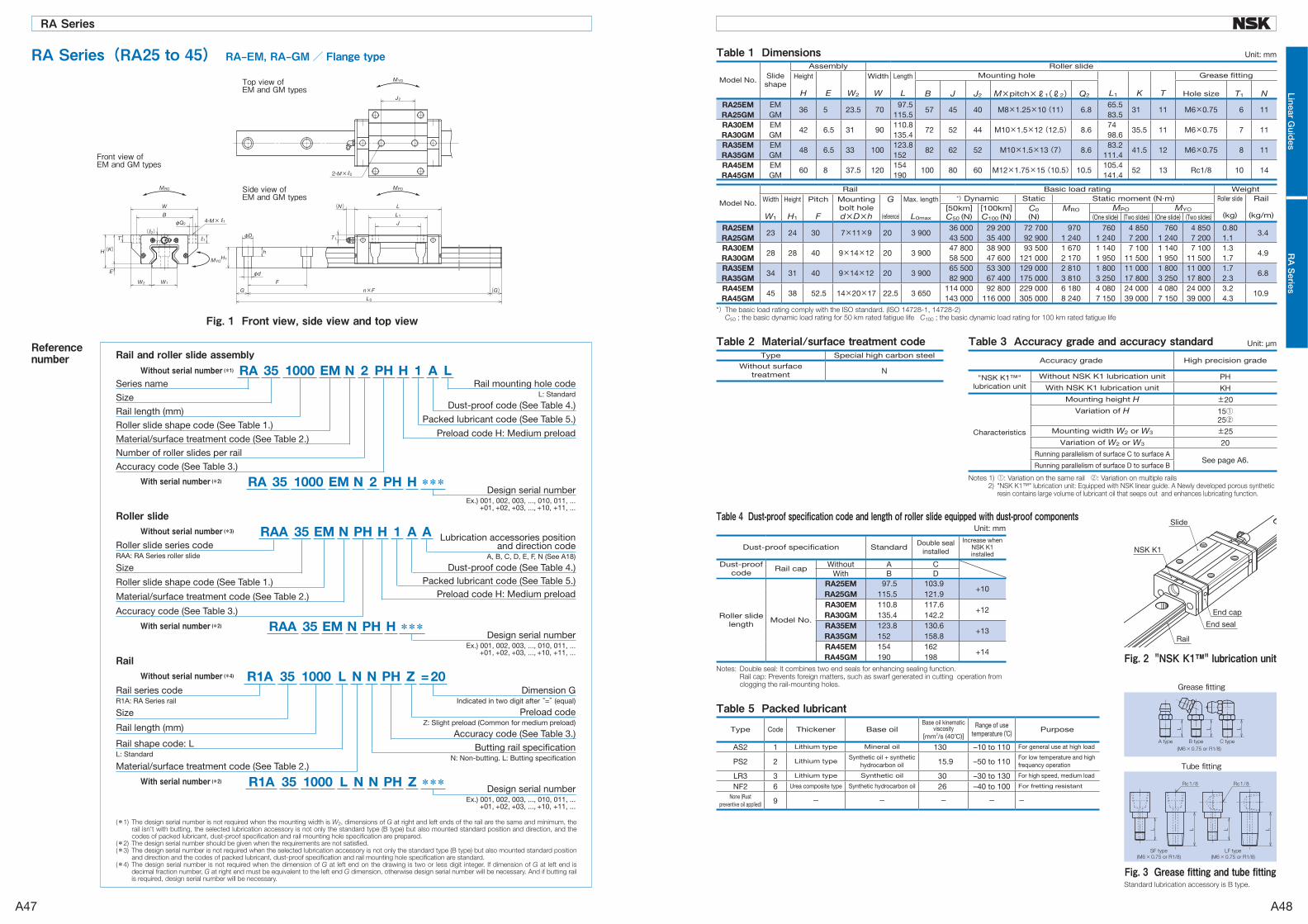
Reference number
Without serial number (*1)Series name
Size
Rail length (mm)
Number of roller slides per rail
Roller slide shape code (See Table 1.)
Material/surface treatment code (See Table 2.)
Dust-proof code (See Table 4.)
Packed lubricant code (See Table 5.)
Accuracy code (See Table 3.)
Rail mounting hole codeL: Standard
Preload code H: Medium preload
Rail and roller slide assemblyPH H 1 A L35 N 21000 EMRA
With serial number (*2)Design serial number
Ex.) 001, 002, 003, ..., 010, 011, ...+01, +02, +03, ..., +10, +11, ...
Size
Rail length (mm)
Rail series codeR1A: RA Series rail
Rail shape code: LL: Standard
Material/surface treatment code (See Table 2.)
Dimension GIndicated in two digit after “=” (equal)
Accuracy code (See Table 3.)
Preload codeZ: Slight preload (Common for medium preload)
Butting rail specificationN: Non-butting. L: Butting specification
Without serial number (*4)Rail
1000 PH Z = 2035 NNLR1A
Design serial numberEx.) 001, 002, 003, ..., 010, 011, ...
+01, +02, +03, ..., +10, +11, ...
With serial number (*2) ***1000 PH Z35 NNLR1A
Without serial number (*3)
Size
Roller slide series codeRAA: RA Series roller slide
Accuracy code (See Table 3.)
Roller slide shape code (See Table 1.)
Material/surface treatment code (See Table 2.)
Lubrication accessories position and direction code
A, B, C, D, E, F, N (See A18)
Preload code H: Medium preload
Dust-proof code (See Table 4.)Packed lubricant code (See Table 5.)
Roller slidePH H 1 A A35 NEMRAA
PH H35 N 21000 EMRA ***
With serial number (*2)Design serial number
Ex.) 001, 002, 003, ..., 010, 011, ...+01, +02, +03, ..., +10, +11, ...
PH H35 NEMRAA ***
Fig. 1 Front view, side view and top view
RA Series(RA25 to 45) RA‒EM, RA‒GM/ Flange typeTop view of EM and GM types
Side view of EM and GM types
Front view of EM and GM types
Table 1 Dimensions
Model No.Slide shape
Assembly Roller slideHeight
H E W2
Width
W
Length
L
Mounting hole
L1 K T
Grease fitting
B J J2 M×pitch×ℓ1(ℓ2) Q2 Hole size T1 NRA25EM EM
36 5 23.5 7097.5
57 45 40 M8×1.25×10 (11) 6.865.5
31 11 M6×0.75 6 11RA25GM GM 115.5 83.5RA30EM EM
42 6.5 31 90110.8
72 52 44 M10×1.5×12 (12.5) 8.674
35.5 11 M6×0.75 7 11RA30GM GM 135.4 98.6RA35EM EM
48 6.5 33 100123.8
82 62 52 M10×1.5×13 (7) 8.683.2
41.5 12 M6×0.75 8 11RA35GM GM 152 111.4RA45EM EM
60 8 37.5 120154
100 80 60 M12×1.75×15 (10.5) 10.5105.4
52 13 Rc1/8 10 14RA45GM GM 190 141.4
Model No.
Rail Basic load rating WeightWidth
W1
Height
H1
Pitch
F
Mountingbolt holed×D×h
G
(reference)
Max. length
L0max
*) Dynamic Static Static moment (N·m) Roller slide Rail[50km]C50 (N)
[100km]C100 (N)
C0(N)
MRO MPO MYO(kg) (kg/m)(One slide) (Two slides) (One slide) (Two slides)
RA25EM23 24 30 7×11×9 20 3 900
36 000 29 200 72 700 970 760 4 850 760 4 850 0.803.4
RA25GM 43 500 35 400 92 900 1 240 1 240 7 200 1 240 7 200 1.1RA30EM
28 28 40 9×14×12 20 3 90047 800 38 900 93 500 1 670 1 140 7 100 1 140 7 100 1.3
4.9RA30GM 58 500 47 600 121 000 2 170 1 950 11 500 1 950 11 500 1.7RA35EM
34 31 40 9×14×12 20 3 90065 500 53 300 129 000 2 810 1 800 11 000 1 800 11 000 1.7
6.8RA35GM 82 900 67 400 175 000 3 810 3 250 17 800 3 250 17 800 2.3RA45EM
45 38 52.5 14×20×17 22.5 3 650114 000 92 800 229 000 6 180 4 080 24 000 4 080 24 000 3.2
10.9RA45GM 143 000 116 000 305 000 8 240 7 150 39 000 7 150 39 000 4.3
Unit: mm
*) The basic load rating comply with the ISO standard. (ISO 14728-1, 14728-2) C50 ; the basic dynamic load rating for 50 km rated fatigue life C100 ; the basic dynamic load rating for 100 km rated fatigue life
Fig. 2 "NSK K1™" lubrication unit
Table 5 Packed lubricantType Code Thickener Base oil
Base oil kinematic viscosity
[mm2/s (40 C)]
Range of usetemperature (°C) Purpose
AS2 1 Lithium type Mineral oil 130 –10 to 110 For general use at high load
PS2 2 Lithium typeSynthetic oil + synthetic
hydrocarbon oil 15.9 –50 to 110For low temperature and high frequency operation
LR3 3 Lithium type Synthetic oil 30 –30 to 130 For high speed, medium load
NF2 6 Urea composite type Synthetic hydrocarbon oil 26 –40 to 100 For fretting resistant
None (Rust preventive oil applied) 9 - - - - -
Tube fitting
Fig. 3 Grease fitting and tube fittingStandard lubrication accessory is B type.
Grease fitting
Table 3 Accuracy grade and accuracy standardTable 2 Material/surface treatment code Unit: μm
Notes 1) ①: Variation on the same rail ②: Variation on multiple rails 2) "NSK K1™" lubrication unit: Equipped with NSK linear guide. A Newly developed porous synthetic
resin contains large volume of lubricant oil that seeps out and enhances lubricating function.
Type Special high carbon steel
Without surface treatment N
Accuracy grade High precision grade
"NSK K1™" lubrication unit
Without NSK K1 lubrication unit PHWith NSK K1 lubrication unit KH
Characteristics
Mounting height H ±20Variation of H 15①
25②Mounting width W2 or W3 ±25
Variation of W2 or W3 20Running parallelism of surface C to surface A
See page A6.Running parallelism of surface D to surface B
Dust-proof specification StandardDouble seal
installed
Increase when NSK K1 installed
Dust-proof code
Rail cap Without A CWith B D
Roller slide length
Model No.
RA25EM 97.5 103.9+10
RA25GM 115.5 121.9RA30EM 110.8 117.6
+12RA30GM 135.4 142.2RA35EM 123.8 130.6
+13RA35GM 152 158.8RA45EM 154 162
+14RA45GM 190 198
Table 4 Dust-proof specification code and length of roller slide equipped with dust-proof componentsUnit: mm
Notes: Double seal: It combines two end seals for enhancing sealing function. Rail cap: Prevents foreign matters, such as swarf generated in cutting operation from clogging the rail-mounting holes.
(*1) The design serial number is not required when the mounting width is W2, dimensions of G at right and left ends of the rail are the same and minimum, the rail isn't with butting, the selected lubrication accessory is not only the standard type (B type) but also mounted standard position and direction, and the codes of packed lubricant, dust-proof specification and rail mounting hole specification are prepared.
(*2) The design serial number should be given when the requirements are not satisfied.(*3) The design serial number is not required when the selected lubrication accessory is not only the standard type (B type) but also mounted standard position
and direction and the codes of packed lubricant, dust-proof specification and rail mounting hole specification are standard.(*4) The design serial number is not required when the dimension of G at left end on the drawing is two or less digit integer. If dimension of G at left end is
decimal fraction number, G at right end must be equivalent to the left end G dimension, otherwise design serial number will be necessary. And if butting rail is required, design serial number will be necessary.
A47 A48
RAシリーズ
Linear Guid
esR
A S
eriesRA Series

B1 B2
Ball S
crew

B3 B4
Ball S
crew

A ball recirculation system is categorically most important, as well as the preload system, to classify the structure
of ball screw. As shown in Table 1, four types of ball recirculation system are used for the NSK ball screws.
Table 1 Ball screw recirculation system
End deflector type Ball return tube type
[Series] End deflector type ・Compact FA PSS type ・Compact FA USS type ・Compact FA FSS type
Middle deflector type ・HSA type for machine tools (HSS shaft end machining lead16 and 20)
[Series] Ball return tube type ・FA type for small equipment ・SA type for machine tools
SRC type ・HSA type for machine tools (HSS shaft end machining lead 5 to 12)
Deflector (bridge) type End cap type
[Series] Deflector (bridge) type ・MS type, Miniature, fine lead ball screws
[Series] End cap type ・FA type for small equipment
B-1 Ball Recirculation System
[Structure] Balls are recirculating through a pipe (ball return
tube) of optimized size, bridging the start and end of recirculation.
[Features] ・ Adapt to various specifications. (screw shaft
diameter, lead)
SRC recirculation system Lead 5 to 12
[Features] ・Smooth pick up of balls in tangential direction
[Structure] Balls are picked up by an end cap placed at
both ends of the nut, and recirculated via a hole through the nut.
[Features] ・ Suitable for high helix and ultra high helix lead
ball screws. ・ Not universal due to complex recirculation
structure.
[Structure] Balls are smoothly picked up in the tangential
direction at the end of nut, and recirculated via a hole in the nut. If the balls are picked up at the middle of the nut, it is called middle deflector type.
[Features] ・ Small nut outside diameter allows compact nut
design. ・ Low noise, high speed.
If the balls are picked up at the middle of the nut, it is called middle deflector type.(Lead 16 and 20)
[Features] ・Smooth pick up of balls in tangential direction
[Structure] Balls are recirculated by a horseshoe shaped
deflector bridging the adjacent ball thread grooves.
[Features] ・ Suitable for fine lead ball screws. ・ Small nut outside diameter, allows compact nut
design.
End deflector
Screw shaft
Ball nut
Ball recirculation hole
B5 B6
Ball S
crew

There are several methods of applying preload to NSK ball screws depending on the application. B-3-1 Lead Accuracy The lead accuracy of NSK precision ball screws (C0
to C5 grades) conforms to the four characteristics
specified in JIS Standards. These characteristics are
expressed by codes ep, �u, �300, and �2π.
Fig. 1 explains the definition of each characteristic,
and shows allowable value of each. Leads are classified
into two categories: C system for positioning; Ct system
for transportation. Tables 4, 5 and 6 show tolerance of
each characteristic.
JIS B1192 sets C type and Cp type standards for
positioning ball screws. NSK uses the specification of
C type only. JIS B1192 specifies Ct1, 3, and 5 grade.
NSK standards are integrated by C type only. Refer to
Table 4 for C type standard tolerance.
B-2 Preload system B-3 Accuracy
Preload system Offset preload (Z-Preload) Oversize ball preload (P-Preload)
Structure
Description
To apply preload, the lead near the center of
the nut is offset by the volume equivalent to
preload (α).
This method is like to creating a preload
system similar to the double nut preload
(D-preload) by a single ball nut, thus enabling
a compact nut design.
Balls slightly larger than the ball groove space
(over-size balls) are inserted to allow them to
contact at four points.
Provides better torque characteristics in the
low torque range.
Nut length Medium Short
Torque characteristics ○ ○
Rigidity ◎ ○
Table 2 Preload system for ball screws
Table 3 Terminology in lead accuracy
Fig. 1 Definition of lead accuracy
Term Code Description Tolerance
Specified travel ls The travel compensates the nominal travel for an elongation caused by an increase of temperature or load.
Travel compensation
T
Value obtained by subtracting the specified travel from the nominal travel based on the useful travel. The value is to compensate for the errors caused by thermal deformation or deformation by load.This value is determined by tests and experience (Table 3).
Actual travel la Actually measured travel
Actual mean travel
lmA straight line that demonstrates the direction of actual travel. This straight line is obtained from the curve that shows actual travel volume by least-squares method or by resembling approximation.
Tolerance on specified travel
ep Obtained by subtracting the specified travel from the actual mean travel.
Table 4
Travel variation� u � 300
� 2π
Maximum range of the actual travel which is between the two straight lines drawn parallel to the actual mean travel. There are three categories as shown below.・ Maximum range relative to the effective length of thread. ・ Maximum range relative to the length of 300 mm anywhere within
the effective length of thread. ・ Maximum range which corresponds to any single rotation (2π
rad.) within the effective length of thread.
Table 4Table 5, 6
Table 5
B7 B8
Ball S
crew

(1) Radial run-out of the support bearing seat relative to the axis of the ball thread of screw shaft.
(2) Radial run-out of the other shaft ends section relative to the axis of the support bearing seat.
(3) Radial run-out of the shoulder of support bearing seat relative to the axis of support bearing seat.
(4) Radial run-out of the nut flange surface, or of the nut end datum surface, relative to the axis of screw shaft.
(5) Radial run-out of the nut outside surface (cylindrical shape) to the axis of screw shaft.
(6) Parallelism of the nut mounting surface to the screw shaft axis. (in case of flat mounting surface)
(7) Total run-out of the screw shaft axis.
B-3-2 Mounting Accuracy and Tolerance of Ball Screws
The accuracy related to mount the ball screws is
specified in the following seven characteristics (Fig. 2).
The tolerance is indicated in the specification drawing.
Detailed tolerances are specified by JIS B1192. For
reference, Table 7 shows standard values of "(7) Total
run-out of the screw shaft axis (straightness of the
screw shaft)". NSK sets stricter tolerance standards
than JIS standards.
Fig. 2 Mounting accuracy of ball screw
Table 4 Tolerance on specified travel (±ep) and travel variation (�u) of the positioning (C type) ball screws
Accuracy grade C3 C5
over or less ±ep �u ±ep �u
- 100 8 8 18 18
100 200 10 8 20 18
200 315 12 8 23 18
315 400 13 10 25 20
400 500 15 10 27 20
500 630 16 12 30 23
630 800 18 13 35 25
800 1 000 21 15 40 27
1 000 1 250 24 16 46 30
1 250 1 600 29 18 54 35
1 600 2 000 35 21 65 40
2 000 2 500 41 24 77 46
2 500 3 150 50 29 93 54
3 150 4 000 60 35 115 65
4 000 5 000 72 41 140 77
5 000 6 300 90 50 170 93
6 300 8 000 110 60 210 115
8 000 10 000 260 140
10 000 12 500 320 170
Unit: μm
Table 5 Tolerance of travel variation relative to 300 mm (� 300) and one revolution (� 2π) of the positioning (C type) ball screws
Table 6 Travel variation (� 300) relative to 300 mm of the transportation (Ct type) ball screws
Unit: μm
Accuracy grade C3 C5
� 300 8 18
� 2π 6 8
Note: ■ to JIS B1192 standards. Values in other areas are NSK standards.
Note: Tolerance on specified travel (ep) of the transportation (Ct type) ball screws is calculated as follows.
ep = ± lu300
× � 300
lu : Effective length of the screw thread
Unit: μm
Accuracy grade Ct7 Ct10
� 300 52 210
Effe
ctiv
e th
read
leng
th, m
m
B9 B10
Ball S
crew

Table 7 Total run-out of the screw shaft axis
Accuracy grade C3 C5
Nominal diameter (mm) over - 8 12 20 32 50 80 - 8 12 20 32 50 80
over or less 8 12 20 32 50 80 125 8 12 20 32 50 80 125
- 125 25 25 20 35 35 35
125 200 35 35 25 20 50 40 40 35
200 315 50 40 30 30 65 55 45 40
315 400 60 50 40 35 25 75 65 55 45 35
400 500 65 50 40 30 80 60 50 45
500 630 70 55 45 35 30 90 75 60 50 40
630 800 70 55 40 35 90 70 55 45
800 1 000 95 65 50 40 30 120 85 65 50 45
1 000 1 250 120 85 60 45 35 150 100 75 60 50
1 250 1 600 160 110 75 55 40 190 130 95 70 55
1 600 2 000 140 95 70 50 170 120 85 65
2 000 2 500 120 85 60 150 110 80
2 500 3 150 160 110 75 200 140 95
3 150 4 000 220 150 100 260 180 120
4 000 5 000 200 130 240 160
5 000 6 300 310 210
6 300 8 000 280
8 000 10 000 370
Unit: μm Operations that use ball screw drives require a motor
torque which is equivalent to the total of following two:
・ Friction torque, i.e. the friction of the ball screw
itself
・ Drive torque which is required for operation
B-4-1 Friction Torque(1) Starting friction torque (Break away torque) A high torque is necessary to start a ball screw. This is
called "starting friction torque" or "break away torque."
This torque is 2 to 2.5 times larger than the dynamic
(friction) torque due to preload which is described below.
The starting friction torque quickly diminishes once the
ball screw begins to move.
(2) Dynamic friction torque (dynamic friction torque due to preload)
When a ball screw is moving, two types of torque
generate: the dynamic friction torque due to preload and
the friction torque associated with ball recirculation. JIS
B1192 sets the standard of dynamic friction torque due
to preload, which is the total of these two torque types.
They are defined in Fig. 4.
The dynamic friction torque due to preload is
calculated by the following formula. When the screw
shaft is rotated as Fig. 3 in the following measuring
conditions, measure the nut holding power F and
then multiple the distance of action line L which is
perpendicular to the direction of the power F .
Tp= F・L … (1)
・ Measuring rotational speed 100 min-1
・ Viscosity of lubrication is ISO VG 68 as prescribed
in JIS K 2009.
・ Remove Seals.
B-4 Friction Torque and Drive Torque
Fig. 3 Preload dynamic torque measuring method
Fig. 4 Definitions of dynamic preloaded drag torque
Ove
rall
leng
th o
f scr
ew s
haft
(mm
)
B11 B12
Ball S
crew

Table 9 Grease for ball screw
Table 10 Checking lubricant and intervals of replenishment
(3) Calculation of basic torque The basic torque of preloaded ball screw Tp0 can be
obtained by the following formula.
Tp0= k Fa0・l2π
≒ 0.014 Fa0√‾‾‾ dm・ l (N・cm) …(2)
In this formula:
Fa0 : Preload (N)
l : Lead (cm)
k : Torque coefficient of ball screw
k= 0.05
√‾‾‾ tanβ
β : Lead angle (deg.)
dm : Ball pitch circle diameter (cm)
Allowable values of torque variation rate relative to
basic torque are regulated as shown in Table 8.
Lithium soap-based grease with base oil viscosity
of 30 to 140 mm2/s (40°C) is recommended for grease
lubrication and oil of ISO VG 32 to 100 for oil lubrication.
In general, a lubricant with low base oil viscosity is
recommended where a ball screw is used for high-
speed operation, and thus requires reducing thermal
elongation of the screw shaft. On the other hand, a
lubricant with high base oil viscosity is recommended
for a low-speed, high-temperature operation, or a high-
load and oscillating operation.
Please consult NSK about greases for high-load
drives and high-temperature applications.
NSK markets "NSK Grease Unit" as the standard
B-4-2 Drive Torque(1) Operating torque of a ball screw(a) Normal drive
The torque when converting rotational motion to
linear motion (normal operation) is obtained by the
following formula.
Ta=Fa・l
2π・η1(N・cm) … (3)
In this formula:
Ta : Normal operation torque (N・cm)
Fa : Axial load (N)
l : Lead (cm)
η1 : Normal efficiency (η1 = 0.9 to 0.95)
(b) Back-drive operation
The torque when convert ing l inear motion to
rotational motion (back-drive operation) is obtained by
the following formula.
Tb=Fa・l・η2
2π(N・cm) … (4)
In this formula:
Tb : Reverse operation torque (N · cm)
η2 : Reverse efficiency (η2 = 0.9 to 0.95)
(c) Dynamic drag torque of the preloaded ball screw
the operation torque of preloaded ball screw can be
obtained by Formula (2).
series products for a variety of applications. NSK
Grease Unit for ball screw lubrication includes:
1) Various types of grease in the bellows-tube which
can be instantly attached to the grease pump
2) Hand grease pump which is compact and easy to
use
3) Nozzles
Table 9 shows NSK greases, and names of other ball
screw greases.
Table 10 explains checking points in lubrication
and standard intervals between replenishments. It is
important to wipe off old grease from the screw shaft
prior to applying new grease. Page C10 also explains in
detail concerning the replenishing methods.
*Refer to page C6 for the nature of NSK greases.
Table 8 Range of allowable values of torque variation rates (Source: JIS B 1192)
Basic torque (N・cm)
Effective length of the screw thread (mm)
4 000 or under Over 4 000 and 10 000 or under
Slenderness ratio(1): 40 or less Slenderness ratio(1): More than 40 and 60 or less
Accuracy grade Accuracy grade Accuracy grade
Over Incl. C0 C1 C2、3 C5 C0 C1 C2、3 C5 C1 C2、3 C5
20 40 ±30% ±35% ±40% ±50% ±40% ±40% ±50% ±60%
40 60 ±25% ±30% ±35% ±40% ±35% ±35% ±40% ±45%
60 100 ±20% ±25% ±30% ±35% ±30% ±30% ±35% ±40% ±40% ±45%
100 250 ±15% ±20% ±25% ±30% ±25% ±25% ±30% ±35% ±35% ±40%
250 630 ±10% ±15% ±20% ±25% ±20% ±20% ±25% ±30% ±30% ±35%
630 1000 ±15% ±15% ±20% ±20% ±25% ±25% ±30%
Notes: 1. Slenderness ratio: The value obtained by dividing the length of the screw thread section of screw shaft (mm) by diameter of the screw shaft (mm).
2. NSK independently sets torque standards which are under 20 N・cm.
B-5 Lubrication of Ball Screw
Product name Thickener Base oilBase oil viscositymm2/s (40°C)
Range of temperature for use °C
Application
NSK Grease AS2 Lithium base Mineral oil 130 –10 to 110 General heavy load
NSK Grease PS2 Lithium base Synthetic oil combined with Synthetic hydrocarbon oil 15.9 –50 to 110 Light load
NSK Grease LR3 Lithium base Synthetic oil 30 –30 to 130 High-speed medium load
NSK Grease LG2 Lithium base Mineral oil combined with Synthetic hydrocarbon oil 32 –20 to 70 For clean environment
NSK Grease NF2 Urea composite type Synthetic hydrocarbon oil 26 –40 to 100 Fretting resistant
Lubricating method Checking intervals Check points Replenish/replacing interval
Intermittent automatic oil supply
Once a week Remaining volume,contamination
Supply oil when checking (depending on the tank volume)
Grease 2 – 3 months after start of use
Clean, foreign matters
Generally once a year (replenish when necessary)
Oil bath Every day, when start to work Oil level Specify according to oil consumption
B13 B14
Ball S
crew

This product is being applied for a patent.
B-6-1 Features NSK K1 is a new, efficient lubrication unit. Equipped
with NSK K1, the ball screws demonstrate a superb
performance as shown below.
● Long-term, maintenance-free usage
In mechanical environments where lubrication is difficult
to apply, long-term running efficiency is maintained by
using the NSK K1 in combination with grease.
[ex.] For automotive component processing lines, etc.
● Does not pollute the environment
A very small volume of grease combined with NSK
K1 can provide sufficient lubrication in the environment
where grease is undesirable as well as in the environment
where high cleanliness is required.
[ex.] Food processing equipment, medical equipment,
flat panel display/semiconductor manufacturing
equipment, etc.
● Good for environments where lubricant is washed away
When used with grease, life of the machine is prolonged
even when the machine is washed entirely by water, or in
an environment where the machine is exposed to rain or
wind.
[ex.] Food processing equipment, housing/construction
machines, etc.
● Maintains efficiency in dusty environment
In environment where oil- and grease-absorbing dust
is produced, long-term efficiency in lubrication and
prevention from foreign inclusions are maintained by
using the NSK K1 in combination with grease.
[ex.] Woodworking machines, etc.
● Comparative duration test of samples with and
without NSK K1
Sample, testing conditions and test result are shown
in Table 11 and Fig. 5.
Without lubricant, operation became impossible after
running 8.6 km. With NSK K1 alone, it was possible to
continue running exceeding 10 000 km.
NSK conducts various tests under different conditions.
Please consult NSK.
(3) Overall nut length after equipped with NSK K1™ The nut length becomes longer than that of standard
ball screws after equipped with NSK K1.
(4) Application examples Ball screws equipped with NSK K1 are maintenance-
free for a long period of time. Its application is expanding
in various industries.
B-6-3 Precautions for useTemperature range for use: Maximum temperature: 50˚C
M o m e n t a r y m a x i m u m
temperature: 80˚C
Chemicals that should not come to contact with K1:
Do not leave NSK K1 in organic solvent, white
kerosene such as hexane, thinner which removes
oil, and rust preventive oil which contains white
kerosene.
Note: Water-type cutting oil, oil-type cutting oil, grease
such as mineral-type AS2 and ester-type PS2 do
not damage K1 Seal.
Note: NSK K1 is not applicable to the Compact FA
series.
B-6-2 Specifications(1) Structure The structure makes it possible to have a stable contact
between the NSK K1 and outside of a ball screw with
moderate force by a garter spring which fits onto outside
of the NSK K1.
NSK K1 is installed between the ball screw nut and
the labyrinth seal. The overall nut length is slightly
longer than that of the standard ball screw.
Combination of NSK standard grease (factory-packed
in the nut) and NSK K1 are standard specifications.
Fig. 6 NSK K1
(2) Accuracy grade and axial play Accuracy grades, clearance and preload specifications
remain unchanged from the existing products. There is a
slight increase in torque due to the equipped NSK K1.
B-6 Equipped with "NSK K1™" Lubrication Unit
Ball screw Shaft dia. 20 mm, lead 20 mm
Lubrication Comparison with only NSK K1 against no lubrication
Speed 4 000 min-1 (80 m/min)
Stroke 600 mm
Table 11 Sample and testing conditions
Fig. 5 Duration test results on ball screws without lubricant
Semiconductor/flat panel display
manufacturing equipmentIndustrial robot
Wood working
machinesMachine tools
Automobile
manufacturing machines
B15 B16
Ball S
crew

Precautions in use(1) Ball screws should be used in a clean environment. Use a dust cover to keep dust and swarf from entering into
the system. Insufficient dust protection causes not only the ball screw function to deteriorate but also brings about
damage to the recirculation components if dust plugs the system. This may result in more serious accident such as a
fall of the table.
(2) For rotational speed in operation, refer to the applicable section of the catalog "Precision Machine Components"
which describes permissible rotational speeds, or to specification drawing furnished by NSK. Exceeding permissible
rotational speed damages recirculation components, and may cause the table to fall. A precaution system is
recommended in vertical use of ball screw.
(3) Overrunning ball nut (removed from the ball thread) causes the balls to fall out, damages recirculation
components, and dent ball groove, resulting in insufficient operation. Continued use under such conditions may
cause premature wear, and damages recirculation components. For these reasons, avoid overrun by all means. If
overrun occurs, please request NSK to check. There will be a minimum charge for this service.
(4) Ball screws are designed to be used at a temperature of less than 80°C. Do not operate at temperatures higher
than this limit. Use at a higher temperature may damage recirculation and seal components. Please consult NSK if it
is necessary to use at a temperature higher than the limit.
When using NSK K1 lubrication unit, the operating temperature should be 50°C or less. (Momentary maximum
temperature in use: 80°C)
Storage(1) Store in the original NSK package. Do not unwrap or tear the inner wrapping if it is not necessary. This allows
dust to enter and rust to set in, and may deteriorate functions.
(2) The following position is recommended when storing ball screws.
①Keep in the NSK original package, and place it flat.
②Place flatly on supports; store in a clean area.
③Hang vertically in a clean place.
Store in the correct position
Prevent dust Rotational speed limitation Do not overrun Temperature limitation
Handling(1) Never disassemble the ball screw. It invites dust to enter, and lowers precision, or may cause an accident.
(2) Once the ball screw is disassembled for some reason, the user should never reassemble the ball screw by
himself. Loss of ball screw function is apt to occur if a mistake is made. Please send the ball screw to NSK for repair
or re-assembly. It will be reworked at the minimum service charge.
(3) The ball screw shaft or nut may fall off due to its own weight. Watch out for such falling object. If it falls, the ball
groove or ball recirculation component may be damaged and their function might be lost. Make certain to return
such item to NSK for check. There will be the minimum charge for this service.
(4) If the recirculation component, the shaft outside, or the ball groove is scratched or damaged by impact,
recirculation operation becomes deficient, and may cause a loss of function.
B-7 Precautions When Handling Ball ScrewsBall screws are precision products. They require careful handling as described below.
Lubrication(1) Confirm the state of lubrication before use. Insufficient lubrication causes loss of ball screw functions in a short
period.
(2) Do not apply any lubrication if grease is already applied to the ball screws. Remove dust or swarf if they stuck to
the greased surface during handling. Wipe the surface with clean white kerosene, and then apply the same type of
new lubricant before use. Avoid using different types of grease at the same time.
Consult NSK for special oil lubricant if it is required to your application.
(3) Check the grease after two to three months of operation. Wipe off the old grease if it is excessively contaminated,
and apply sufficient volume of a fresh coat of grease. After the initial check, check and replenish the grease
approximately every year. Check more often if environment requires.
Note: Refer to page C6 for lubrication.
Confirm lubrication
Do not disassemble Do not reassemble Watch out for falling objects Handle with care Do not apply shock
B17 B18
Ball S
crew
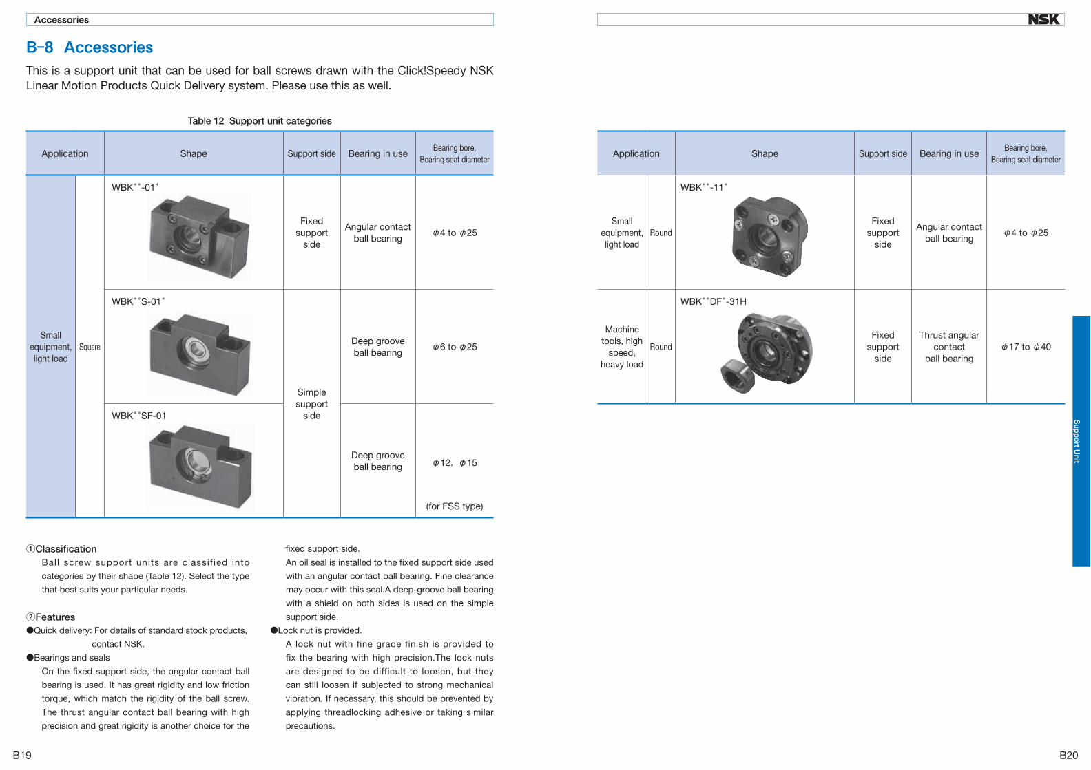
B-8 AccessoriesThis is a support unit that can be used for ball screws drawn with the Click!Speedy NSK Linear Motion Products Quick Delivery system. Please use this as well.
Table 12 Support unit categories
Application Shape Support side Bearing in useBearing bore,
Bearing seat diameter
Small equipment, light load
Square
WBK**-01*
Fixed support
side
Angular contactball bearing
φ4 to φ25
WBK**S-01*
Simple support
side
Deep grooveball bearing
φ6 to φ25
WBK**SF-01
Deep grooveball bearing φ12,φ15
(for FSS type)
①Classification Bal l screw support units are classif ied into
categories by their shape (Table 12). Select the type
that best suits your particular needs.
②Features●Quick delivery: For details of standard stock products,
contact NSK.
●Bearings and seals
On the fixed support side, the angular contact ball
bearing is used. It has great rigidity and low friction
torque, which match the rigidity of the ball screw.
The thrust angular contact ball bearing with high
precision and great rigidity is another choice for the
fixed support side.
An oil seal is installed to the fixed support side used
with an angular contact ball bearing. Fine clearance
may occur with this seal.A deep-groove ball bearing
with a shield on both sides is used on the simple
support side.
●Lock nut is provided.
A lock nut with fine grade finish is provided to
fix the bearing with high precision.The lock nuts
are designed to be difficult to loosen, but they
can still loosen if subjected to strong mechanical
vibration. If necessary, this should be prevented by
applying threadlocking adhesive or taking similar
precautions.
Application Shape Support side Bearing in useBearing bore,
Bearing seat diameter
Small equipment, light load
Round
WBK**-11*
Fixed support
side
Angular contactball bearing
φ4 to φ25
Machinetools, high
speed,heavy load
Round
WBK**DF*-31H
Fixed support
side
Thrust angular contact
ball bearingφ17 to φ40
B19
Accessories
B20
Sup
po
rt Unit

③Reference number coding
(For high speed and heavy load)
Example:
H: High speed type
Bearing combination codeDF: Face to face duplex combinationDFD: Face to face triplex combinationDFF: Face to face quadruplex combination
Product code for support unit
Nominal size code (internal bore of bearing)
H25 31WBK DF -
(For light load)
Example:
No code or A: For general use B: Low-profile type (only for square type) C: For clean environment use M: Miniature general-purpose use W: Lost-wax product
01: Square type11: Round type
Product code for support unit
Nominal size code*
Mounting code No code: Fixed support unit S: Simple support unit SF: Simple support unit (for FSS) R: Fixed support unit (support kit for miniature ball screws)
A08 01WBK S -
*) In case of simple support unit, please note that the nominal size code of 12 or less does not strictly represent internal bore of bearing in millimeters. Please refer to the dimensional table for internal bore of bearing.
(1) Support Units for Light Load and Small Equipment
Support units for light load and small equipment
provide both fixed and support side bearing assemblies
to support screw shafts. They provide all required parts
such as bearing locknuts so that you can mount them
directly to NSK standard ball screws, of which shaft
ends are machined.
Please refer to the dimensions l isted on the
dimension table for the configuration of standard screw
shaft ends for NSK standard ball screws with blank
shaft ends. For ball screws for transfer equipment, you
require optional spacers when mounting fixed support
side support units.
①Features●Prompt delivery
Support units are standard products.
●Best selection of bearings for your application
General use support units for fixed support side
are equipped with highly rigid angular contact ball
bearings that have been assembled with proper
preload, and packed with the appropriate volume of
grease. On the other hand, clean support units for
fixed support side uses low dust emission grease,
and low torque special bearings. Sealed deep
groove ball bearings are used for simple support
side units for both general and clean environment
use.
B21
Accessories
B22
Sup
po
rt Unit

●Accessories
Support units provide everything necessary for
mounting ball screws to machines.
(Please refer to the table below.)
* Do not disassemble fixed support side units as
they are equipped with bearings and oil seals
●Antirust treatment
The table on the right shows the surface treatment
for the bearing housing, and material of small parts.
Fixed support side Simple support side
Part No. Name of parts Part No. Name of parts
① Bearing housing ⑤ Bearing housing
② Spacer ⑥ Bearing
③ Locknut ⑦ Snap ring
④ Set screwwith brass pad
General support unit
Bearings and grease Angular contact ball bearings, PS2
Surface treatment Black oxide
Screws and snap rings Standard material
Clean support unit
Bearing ・ grease Special bearings, LG2
Surface treatment Low temperature chrome plating
Set screw and snap ring material Stainless steel
②Features of Clean Support Unit●Outstanding low dust emission
Clean support unit uses "NSK clean grease LG2" which
has a proven feature of low dust emission. It reduces
dust emission to 1/10 of general support units.
●Low torque
It features low torque characteristics because of special
bearings. (50% lower than general support unit.)
●High antirust specification
Low temperature chrome plating is applied to bearing
housings, retaining plates, locknuts and spacers to
improve antirust properties. Moreover, bolts and snap
rings are made of stainless steel.
The table below shows the surface treatment of the
bearing housing and material of small parts.
B23
Accessories
B24
Sup
po
rt Unit

WBK**-01M
WBK**-01*
Support Units for Light Load and Small Equipment
View S (WBK06‒15) View S (WBK17‒20)
Reference No.Tightening torque (reference) [N·cm]
Locknut Set screw
WBK04-**WBK06-**WBK08-**WBK10-**WBK12-**WBK15-**WBK17-**WBK20-**WBK25-**
10019023028063079091016702060
69 (M3)69 (M3)69 (M3)147 (M4)147 (M4)147 (M4)147 (M4)147 (M4)490 (M6)
Reference No. Use d1 A B C D E F L J K R T U NCounterbore dimensions Mass
(kg)
Locknut screw
M
Attached bearing for support side
H P Q W X Y Z
WBK04-01M General 4 27 17 10 6 14 10 - 14 5.5 7 9 2.5 2 7 - - 21 3.5 - - 0.03 M4×0.5 -
WBK06-01M General 6 35 22.5 13 8 19 12 - 17 7.5 9.5 12 2.5 2.5 8.5 - - 26 5.5 - - 0.05 M6×0.75 -
WBK06-01A*1 General 6 42 25 13 20 18 12 20 20 5.5 - - - 3.5 10 - - 30 5.5 9.5 11 0.15 M6×0.75 -
WBK08-01A*1 General
8
52 32 17 26 25
14
23 23 7
- - -4 11.5
- -38 6.6 11 12 0.25
M8×1
606ZZ
WBK08-01B Low type 62 31 15.5 31 - 21.5 25.5 4.5 3.5 11 46 9 14 18 0.3 606ZZ
WBK08-01C*1 Clean environment 52 32 17 26 25 23 23 7 4 11.5 38 6.6 11 12 0.25 606VV
WBK10-01A General
10 70
43 25 35 36
17 24 30 5.5 - - - 6 12 - - 52 9 14
11 0.5
M10×1
608ZZ
WBK10-01B Low type 38 20 38 - 19 0.45 608ZZ
WBK10-01C Clean environment 43 25 35 36 11 0.5 608VV
WBK12-01A General
12 70
43 25 35 36
19 24 30 5.5 - - - 6 12 - - 52 9 14
11 0.5
M12×1
6000ZZ
WBK12-01B Low type 38 20 38 - 19 0.4 6000ZZ
WBK12-01C Clean environment 43 25 35 36 11 0.5 6000VV
WBK15-01A General
15 80
50 30 40 41
22 25 31 12 - - - 5 12.5 - - 60 11 17
15 0.7
M15×1
6002ZZ
WBK15-01B Low type 42 22 42 - 23 0.6 6002ZZ
WBK15-01C Clean environment 50 30 40 41 15 0.7 6002VV
WBK17-01A General 17 86 64 39 55 50 24 35 44 7 - - - 7 - 19 8 68 9 14 11 1.3 M17×1 6203ZZ
WBK20-01 General 20 95 58 30 45 56 30 42 52 10 - - - 10 - 22 10 75 11 17 15 1.4 M20×1 6204ZZ
WBK25-01W General 25 105 68 35 25 66 36 48 61 13 - - - 14 - 30 9 85 11 - - 1.9 M25×1.5 6205ZZ
Fixed support side support unit (square type) Units: mm
Notes: 1. Use datum surface A for mounting to machine base. 2. Tighten set screw after locknut has been adjusted and tightened. 3. Insert brass pad provided with unit into locknut set screw hole, then insert and tighten the set screw. 4. Deep groove ball bearing and snap ring are also provided for simple support side.
(except WBK04-01M, WBK06-01M and WBK06-01A)
5. Bearings for WBK04-01M and WBK06-01M are equipped with non-contact metal shield. *1) For retaining cover side of WBK06-01A, WBK08-01A and WBK08-01C, there are no seals. 6. Contact NSK if the rotational speed is 50 min-1 and below.
View S (WBK25)
B25
Accessories
B26
Sup
po
rt Unit
Support Unit (Support Units for Light Load and Small Equipment)

View X-X (example 1) (example 2)
WBK**-11M
WBK**-11*
Reference No.Tightening torque (reference) [N·cm]
Locknut Set screw
WBK04-**
WBK06-**
WBK08-**
WBK10-**
WBK12-**
WBK15-**
WBK17-**
WBK20-**
WBK25-**
100
190
230
280
630
790
910
1670
2060
69 (M3)
69 (M3)
69 (M3)
147 (M4)
147 (M4)
147 (M4)
147 (M4)
147 (M4)
490 (M6)
Reference No. Use d1 A C D1 D2 E H L K F N U P QCounterbore dimensions Mass
(kg)
Locknut screw
M
Attached bearing for support side
J W X Y Z
WBK04-11M General 4 14 26 14 14 13.5 8.5 7 1.5 5.5 6.6 10 2.6 2.4 3 20 3.5 - - 0.02 M4×0.5 -
WBK06-11M General 6 19 34 19 18.5 17 12 9.5 2.5 7.5 8 12 3 2 4 26 4.5 - - 0.04 M6×0.75 -
WBK06-11* General 6 28 35 22 - 20 13 9.5 3.5 5.5 6.5 12 4.5 2.5 7 28 2.9 5.5 3.5 0.1 M6×0.75 -
WBK08-11B High-load type
8
42 52 34
-
25.5 15.5 12 3.5 4.5 7
14
6
4
10 42 4.5 8
4
0.2
M8×1
606ZZ
WBK08-11* General
35 43 28 23 14 10 4 7 8 5 9 35 3.4 6.5 0.15606ZZ
WBK08-11C* Clean environment 606VV
WBK10-11 General10 42 52 34 - 27 17 12 5 7.5 8.5 17 6 4 10 42 4.5 8 4 0.2 M10×1
608ZZ
WBK10-11C Clean environment 608VV
WBK12-11 General12 44 54 36 - 27 17 12 5 7.5 8.5 19 6 4 10 44 4.5 8 4 0.25 M12×1
6000ZZ
WBK12-11C Clean environment 6000VV
WBK15-11 General15 52 63 40 - 32 17 11 6 12 14 22 8 7 15 50 5.5 9.5 6 0.4 M15×1
6002ZZ
WBK15-11C Clean environment 6002VV
WBK20-11 General 20 68 85 57 - 52 30 20 10 10 14 30 14 8 22 70 6.6 11 10 1.1 M20×1 6204ZZ
WBK25-11 General 25 79 98 63 - 57 30 20 10 13 20 36 17 10 27 80 9 15 13 1.5 M25×1.5 6205ZZ
Fixed support side support unit (round type) Units: mm
Notes: 1. Tighten set screw after locknut has been adjusted and tightened. 2. Insert brass pad provided with unit into locknut set screw hole, then insert and tighten the set screw. 3. Deep groove ball bearing and snap ring are also provided for simple support side.
(except WBK04-11M, WBK06-11M and WBK06-11)
4. Bearings for WBK04-11M and WBK06-11M are equipped with non-contact metal shield. *For retaining cover side of WBK06-11, WBK08-11 and WBK08-11C, there are no seals. 5. Contact NSK if the rotational speed is 50 min-1 and below.
B27
Accessories
B28
Sup
po
rt Unit
Support Unit (Support Units for Light Load and Small Equipment)

Reference No. Use d2 A B C D E RCounterbore dimensions Mass
(kg)W X Y Z
WBK08S-01 General6
52 32 17 26 25 15 38 6.6 11 12 0.15WBK08S-01B Low type 62 31 15.5 31 - 16 46 9 14 18 0.2 WBK08S-01C Clean environment 52 32 17 26 25 15 38 6.6 11 12 0.15WBK10S-01 General
8 70 43 25 35 36 20 52 9 14 11 0.4 WBK10S-01C Clean environmentWBK12S-01 General
1070
43 25 35 36
20 529 14
11 0.35WBK12S-01B Low type 38 20 38 - 19 0.4 WBK12S-01C Clean environment
43 25 35 36 110.35
WBK12SF-01*1 General
120.3
WBK12SF-01B*1 Low type 62 31 15.5 31 - 18 46 18 0.2
WBK15S-01 General
1580
50 30 40 41
2060
9 14
11 0.45WBK15S-01B Low type 42 22 42 - 23 0.4 WBK15S-01C Clean environment 50 30 40 41
110.45
WBK15SF-01*1 General
7043 25 35 36
52 0.3 WBK15SF-01B
*1 Low type 38 20 38 - 18 19WBK17S-01 General 17 86 64 39 55 50 23 68 9 14 11 0.8 WBK20S-01 General
2095 58 30 45 56 26 75
11 1715 0.8
WBK20SF-01B Low type 80 42 22 42 - 22 60 23 0.4 WBK25S-01W
General 25105 68 35 25 66 30 85 11 - - 0.9
WBK25SF-01*1 95 58 30 45 56 22 75 11 17 15 0.55
Simple support side support unit (square type)
Specifications of support unit
Units: mm
Notes: 1. Use datum surface B for mounting to machine base. 2. For reference No. 12 or lower numbers, note that the reference numbers and inner dimensions of the bearing are different. 3. WBK ** SF is a type supporting screw shaft OD. 4. See page B30 for bearing reference number and the basic dynamic load rating in the radial direction. 5. *1 is exclusive for FSS type.
Notes: 1. *1 is exclusive for FSS type. 2. Permissible axial load is 0.7 times of limiting axial load.
Fixed support side support unit Simple support side support unit
Reference No. Use
Axial direction Maximumstarting torque[N・cm]
Reference No.Bearing
reference No.
Radial directionBasic dynamic
load ratingC [N]
Basic dynamic load rating Ca [N]
Load limit[N]
Rigidity[N/μm]
WBK04-01M General 1 470 464 39 0.2 - - -
WBK04-11M General 1 470 464 39 0.2 - - -
WBK06-01A General 2 670 1 040 28 0.49 - - -
WBK06-01M General 2 760 854 60 0.35 - - -
WBK06-11 General 2 670 1 040 28 0.49 - - -
WBK06-11M General 2 760 854 60 0.35 - - -
WBK08-01A General 4 400 1 450 49 0.88 WBK08S-01 606ZZ 2 260
WBK08-01B Low type 6 600 2 730 94 1.9 WBK08S-01B
WBK12SF-01B*1
606ZZ6801ZZ
2 260 1 920
WBK08-01C Clean environment 3 100 1 100 36 0.52 WBK08S-01C 606VV 2 260
WBK08-11 General 4 400 1 450 49 0.88 WBK08S-01 606ZZ 2 260
WBK08-11B High load 6 600 2 730 94 1.9 - 606ZZ 2 260
WBK08-11C Clean environment 3 100 1 100 36 0.52 WBK08S-01C 606VV 2 260
WBK10-01A General 6 600 2 730 94 1.9 WBK10S-01
WBK12SF-01*1
608ZZ6001ZZ
3 300 5 100
WBK10-01B Low type 6 600 2 730 94 1.9 - 608ZZ 3 300
WBK10-01C Clean environment 4 250 1 364 50 1.1 WBK10S-01C 608VV 3 300
WBK10-11 General 6 600 2 730 94 1.9 WBK10S-01 608ZZ 3 300
WBK10-11C Clean environment 4 250 1 364 50 1.1 WBK10S-01C 608VV 3 300
WBK12-01A General 7 100 3 040 104 2.1 WBK12S-01
WBK15SF-01*1
6000ZZ6902ZZ
4 550 4 350
WBK12-01B Low type 7 100 3 040 104 2.1 WBK12S-01B
WBK15SF-01B*1
6000ZZ6902ZZ
4 550 4 350
WBK12-01C Clean environment 4 700 2 443 57 1.2 WBK12S-01C 6000VV 4 550
WBK12-11 General 7 100 3 040 104 2.1 WBK12S-01 6000ZZ 4 550
WBK12-11C Clean environment 4 700 2 443 57 1.2 WBK12S-01C 6000VV 4 550
WBK15-01A General 7 600 3 380 113 2.4 WBK15S-01 6002ZZ 5 600
WBK15-01B Low type 7 600 3 380 113 2.4 WBK15S-01B
WBK20SF-01B*1
6002ZZ6804ZZ
5 600 4 000
WBK15-01C Clean environment 5 100 2 757 63 1.3 WBK15S-01C 6002VV 5 600
WBK15-11 General 7 600 3 380 113 2.4 WBK15S-01 6002ZZ 5 600
WBK15-11C Clean environment 5 100 2 757 63 1.3 WBK15S-01C 6002VV 5 600
WBK17-01A General 13 400 5 800 120 3.5 WBK17S-01 6203ZZ 9 550
WBK20-01 General 17 900 8 240 155 6.2 WBK20S-01
WBK25SF-01*1
6204ZZ6005ZZ
12 80010 100
WBK20-11 General 17 900 8 240 155 6.2 WBK20S-01W 6204ZZ 12 800
WBK25-01W General 20 200 10 000 192 7.2 WBK25S-01W 6205ZZ 14 000
WBK25-11 General 20 200 10 000 192 7.2 WBK25S-01W 6205ZZ 14 000
WBK04R-11 General 615 490 6.5 0.59 - - -
WBK06R-11 General 1 280 930 9 0.59 - - -
B29
Accessories
B30
Sup
po
rt Unit
Support Unit (Support Units for Light Load and Small Equipment)

Support kits for ball screws for transfer equipment Support kits are for RMA type ball screw.
In case of RMA1002 or larger rolled ball screws, please use support units for general use.
Spacer When using a fixed support unit, it may require an optional spacer to have an effective shoulder surface at where
the ball thread is threaded to the end of the shoulder. This is common for the R series for transporting ball screws.
Notes:1. Oscillate bearings slowly so that they fall into place in which run-out of mounting surface is minimal, and then tighten locknut.2. Support kit is on provisional shaft (bolt) during shipping.3. When securing support unit on shaft, insert brass pad that is provided with support unit into lock nut hole, and then tighten
set screw.
Units: mm
Units: mm
Reference No. A C d D1 D2 E F G H W U MMass(kg)
WBK04R-11 14 25 4 13 12.5 9 5 5 2.5 19 10 M4×0.5 0.13
WBK06R-11 19 30 6 18 17 11 5 6.8 2.5 24 12 M6×0.75 0.23
Reference No.Applicable ball
screw
Locknut tightening torque (reference) [N・cm]
Set screw tightening torque (reference) [N・cm]
WBK04R-11 RMA0601 100 38 (M2.5)
WBK06R-11
RMA0801RMA0801.5RMA0802
190 69 (M3)
Reference No.
Internal diameter
d
Outside diameter
D
Width
B
Mass
(g)
Applicable support unit
WBK06K 6 9.5 5.0 2 WBK06-**
WBK08K 8 11.5 5.5 2 WBK08-**
WBK10K 10 14.5 5.5 4 WBK10-**
WBK12K 12 15.0 5.6 3 WBK12-**
WBK15K 15 19.5 10.0 10 WBK15-**
WBK17K 17 24.4 7.0 13 WBK17-**
WBK20K 20 25.5 11.0 17 WBK20-**
WBK25K 25 32.0 14.0 34 WBK25-**
B31
Accessories
B32
Sup
po
rt Unit
Support Unit (Support Units for Light Load and Small Equipment)

B-9 Ball screw support bearings
Features The bearings of this series are double-row angular contact
thrust ball bearings with a 60° contact angle and a single outer
ring. The specifications are the same as those of the NSKTAC
bearings, both series being optimized for the support of
ball screws in machine tools. All BSBD Series bearings are
equipped with a rubber contact seal and prepacked with high
performance grease.
NSKHPS™ BSBD Series The BSBD Series are double-row bearing units for the support of ball screws that can accurately and quickly position a work piece or a spindle unit.
●BSF Type The BSBD Series are double row angular contact thrust ball bearings in a back-to-back arrangement, with a single
outer ring. The BSF type of bearings is with bolt holes on the outer ring for easy direct mounting. Two lubrication
holes – one in the outer surface and one in the face of the outer ring – allow for relubrication during operation if
required. If not used, these holes are closed off with set screws. An extraction groove on the outer surface of the
outer ring aids removal of the bearing.Note: BSF type bearings are supplied with seal and set screws included. Mounting bolts are not included.
NSKHPS BSBD Series
●Seal Rubber contact seal on both sides. Triple lip structure
provides high grease sealing performance and dust
resistance.
Note: P2B is an accuracy class specific to the BSBD Series, indicating the following: Running accuracy: ISO Class 2 Others: NSK-specific
Single product
Bearing number Example:
Bearing type
Bore diameter
F: Flange typePreload
Accuracy
Outer diameter Seal type
H30BS F DDU P2B80
B33
Accessories
B34
Accesso
ries

Notes: 1. Permissible axial load equals 0.7 times of limiting axial load. The values refer to the limiting load of the bearing only, without taking the mounting bolts into account.
2. The values indicate starting torque of preloaded bearings, not including seal torque. 3. Inner rings can be separable easily. Please push or pull bearings by clamping inner ring at mounting and dismounting.
Bearing Numbers
Boundary Dimensions (mm) Basic Load Rating (kN) Limiting Axial Load
(kN)
Axial Rigidity (N/µm)
Mass
(kg)
Limiting speed(min-1)
Reference Dimensions (mm) Mounting Bolts Preload
(N)
Starting torque (N・m)
Recommended Clamping Force
(N)d D B r(min)
r1(min)
Ca(Dynamic)
Coa(Static)
Grease d1 D1 J d2 ℓ b t Bolt Dia. Number of Bolts H
BSF2575 25 75 28 0.6 0.6 28.3 48.0 34.0 750 0.73 5 100 37.6 48 58 6.8 19 3 4 x 90° M6 4 2 245 0.16 8 100
BSF3080 30 80 28 0.6 0.6 30.0 55.5 38.5 850 0.79 4 500 42.6 53 63 6.8 19 3 6 x 60° M6 6 2 625 0.19 8 600
BSF30100 30 100 38 0.6 0.6 60.5 94.0 66.5 950 1.71 3 900 49.1 64.4 80 8.8 30 3 8 x 45° M8 8 4 855 0.59 11 100
BSF Type Single product
B35
Accessories
B36
Accesso
riesBSBD Series Bearings for ball screw support

○Fluoride low temperature chrome plating ・ Fluoroplastic coating is provided following
the low temperature chrome plating. ・ Resistance to corrosion is higher than
low temperature chrome plating.
Table 3 Lubricant codeTypes of lubricant Code Thickener Base oil Base oil kinematic viscosity
[mm2/s (40°C)]Range of use
temperature (°C) Application
AS2 1 Lithium type Mineral oil 130 –10 to 110 For general use at high loadPS2 2 Lithium type Synthetic oil + synthetic hydrocarbon oil 15.9 –50 to 110 For light loadLR3 3 Lithium type Synthetic oil 30 –30 to 130 For high speed, medium loadLG2 4 Lithium type Mineral oil + synthetic hydrocarbon oil 32 –20 to 70 For clean environmentLGU 5 Diurea Synthetic hydrocarbon oil 95.8 –30 to 120 For clean environmentNF2 6 Urea composite type Synthetic hydrocarbon oil 26 –40 to 100 For fretting resistance
Rust preventive oil 9 - - - - -
Table 2 Surface treatmentTypes of surface treatment No surface treatment Fluoride low temperature chrome plating
Code N F
Table 1 Preload system/Axial play codePreload system/Axial play Axial play 0.005 or less
Code T
Compact FA PSS Type Screw shaft diameter ø6, Lead 8
Specification
***N N2 C 0151P T 06 08A
Surface treatment N : None (see table 2)
Design serial number
Overall length of shaft (mm)
Nut direction/Shaft end shape code (see table 4)
Lubrication component N : None
Lubricant code 2 : PS2 (see table 3)
Lead (mm)
Nut code A : End Deflector Type
Screw shaft diameter (mm)
Preload system/Axial play codeT : Axial play 0.005 or less (see table1)
Accuracy grade P : JIS C5 grade
Click!Speedy Reference Number
Nut specification Screw shaft dimensions (mm)
Model No. Screw shaft diameter (mm)
Lead(mm)
Basic load ratingThread length
Lt Supported length
LaOverall length
LoShaft end length
L1Shaft end length
L2Dynamic
Ca (N)StaticCoa (N)
BSS0608-2E 6 8 690 805 32.0 to120.0
40.5 to128.5
63.5 to151.5
1.0 to15.0
19.0 to33.0
Table 4 Nut direction/Shaft end shape codeShaft end shape Free - Fixed Free - FixedNut direction Flange side : Fixed Flange side : Free
Code C G
Shape
1. Shaft end shape of fixed support side
Additional element
None
Flats
Dimensional change or addition of element is possible on the gray area of the following drawing. In this case, "Design serial number" is added to the reference number by Click!Speedy software.
Table 5 Shaft end shape
B37
Compact FA PSS Type
B38
Ball S
crewP
SS

Specification
***N N2 C 0151P T 06 08B
Surface treatment N : None (see table 2)
Design serial number
Overall length of shaft (mm)
Nut direction/Shaft end shape code (see table 4)
Lubrication component N : None
Lubricant code 2 : PS2 (see table 3)
Lead (mm)
Nut code B : End Deflector Type
Screw shaft diameter (mm)
Preload system/Axial play codeT : Axial play 0.005 or less (see table1)
Accuracy grade P : JIS C5 grade
Click!Speedy Reference Number
Compact FA PSS Type Screw shaft diameter ø6, Lead 8
Nut specification Screw shaft dimensions (mm)
Model No. Screw shaft diameter (mm)
Lead (mm)
Basic load ratingThread length
LtSupported length
LaOverall length
LoShaft end length
L1Shaft end length
L2Dynamic
Ca (N)StaticCoa (N)
BSS0608-4E 6 8 1 480 1 940 48.0 to120.0
56.5 to128.5
79.5 to151.5
1.0 to15.0
19.0 to33.0
○Fluoride low temperature chrome plating ・ Fluoroplastic coating is provided following
the low temperature chrome plating. ・ Resistance to corrosion is higher than
low temperature chrome plating.
Table 3 Lubricant code
Table 2 Surface treatmentTypes of surface treatment No surface treatment Fluoride low temperature chrome plating
Code N F
Table 1 Preload system/Axial play codePreload system/Axial play Axial play 0.005 or less
Code T
Types of lubricant Code Thickener Base oil Base oil kinematic viscosity[mm2/s (40°C)]
Range of use temperature (°C) Application
AS2 1 Lithium type Mineral oil 130 –10 to 110 For general use at high loadPS2 2 Lithium type Synthetic oil + synthetic hydrocarbon oil 15.9 –50 to 110 For light loadLR3 3 Lithium type Synthetic oil 30 –30 to 130 For high speed, medium loadLG2 4 Lithium type Mineral oil + synthetic hydrocarbon oil 32 –20 to 70 For clean environmentLGU 5 Diurea Synthetic hydrocarbon oil 95.8 –30 to 120 For clean environmentNF2 6 Urea composite type Synthetic hydrocarbon oil 26 –40 to 100 For fretting resistance
Rust preventive oil 9 - - - - -
Table 4 Nut direction/Shaft end shape codeShaft end shape Free - Fixed Free - FixedNut direction Flange side : Fixed Flange side : Free
Code C G
Shape
1. Shaft end shape of fixed support side
Additional element
None
Flats
Dimensional change or addition of element is possible on the gray area of the following drawing. In this case, "Design serial number" is added to the reference number by Click!Speedy software.
Table 5 Shaft end shape
B39
Compact FA PSS Type
B40
Ball S
crewP
SS

Specification
***N N2 C 0151P T 06 12A
Surface treatment N : None (see table 2)
Design serial number
Overall length of shaft (mm)
Nut direction/Shaft end shape code (see table 4)
Lubrication component N : None
Lubricant code 2 : PS2 (see table 3)
Lead (mm)
Nut code A : End Deflector Type
Screw shaft diameter (mm)
Preload system/Axial play codeT : Axial play 0.005 or less (see table1)
Accuracy grade P : JIS C5 grade
Click!Speedy Reference Number
Compact FA PSS Type Screw shaft diameter ø6, Lead 12
Nut specification Screw shaft dimensions (mm)
Model No. Screw shaft diameter (mm)
Lead(mm)
Basic load ratingThread length
LtSupported length
LaOverall length
LoShaft end length
L1Shaft end length
L2Dynamic
Ca (N)StaticCoa (N)
BSS0612-2E 6 12 665 800 40.0 to120.0
50.0 to130.0
73.0 to153.0
1.0 to15.0
19.0 to33.0
○Fluoride low temperature chrome plating ・ Fluoroplastic coating is provided following
the low temperature chrome plating. ・ Resistance to corrosion is higher than
low temperature chrome plating.
Table 3 Lubricant code
Table 2 Surface treatmentTypes of surface treatment No surface treatment Fluoride low temperature chrome plating
Code N F
Table 1 Preload system/Axial play codePreload system/Axial play Axial play 0.005 or less
Code T
Types of lubricant Code Thickener Base oil Base oil kinematic viscosity[mm2/s (40°C)]
Range of use temperature (°C) Application
AS2 1 Lithium type Mineral oil 130 –10 to 110 For general use at high loadPS2 2 Lithium type Synthetic oil + synthetic hydrocarbon oil 15.9 –50 to 110 For light loadLR3 3 Lithium type Synthetic oil 30 –30 to 130 For high speed, medium loadLG2 4 Lithium type Mineral oil + synthetic hydrocarbon oil 32 –20 to 70 For clean environmentLGU 5 Diurea Synthetic hydrocarbon oil 95.8 –30 to 120 For clean environmentNF2 6 Urea composite type Synthetic hydrocarbon oil 26 –40 to 100 For fretting resistance
Rust preventive oil 9 - - - - -
Table 4 Nut direction/Shaft end shape codeShaft end shape Free - Fixed Free - FixedNut direction Flange side : Fixed Flange side : Free
Code C G
Shape
1. Shaft end shape of fixed support side
Additional element
None
Flats
Dimensional change or addition of element is possible on the gray area of the following drawing. In this case, "Design serial number" is added to the reference number by Click!Speedy software.
Table 5 Shaft end shape
10 18
6.5
φ27
2.5
12 44
0 -0.006
5 0-0.2
20
φ14
φ14
E
M4X0.54GA
(hardened area)
Lo
Lt
La
L1
L2
C0.1C0.3 C0.3 C0.3
0 -0.050
MAX 5(Not case hardened)
MAX 5(Not case hardened)
φ4-0.004
-0.009
φ3 h6
φ6
2-φ3.4 drill thru.(equally spaced)
View X-X
7.5 7.515
PCD 21
B41
Compact FA PSS Type
B42
Ball S
crewP
SS

Specification
***N N2 C 0151P T 06 12B
Surface treatment N : None (see table 2)
Design serial number
Overall length of shaft (mm)
Nut direction/Shaft end shape code (see table 4)
Lubrication component N : None
Lubricant code 2 : PS2 (see table 3)
Lead (mm)
Nut code B : End Deflector Type
Screw shaft diameter (mm)
Preload system/Axial play codeT : Axial play 0.005 or less (see table1)
Accuracy grade P : JIS C5 grade
Click!Speedy Reference Number
Compact FA PSS Type Screw shaft diameter ø6, Lead 12
Nut specification Screw shaft dimensions (mm)
Model No. Screw shaft diameter (mm)
Lead(mm)
Basic load ratingThread length
LtSupported length
LaOverall length
LoShaft end length
L1Shaft end length
L2Dynamic
Ca (N)StaticCoa (N)
BSS0612-4E 6 12 1 430 1 970 64.0 to120.0
74.0 to130.0
97.0 to153.0
1.0 to15.0
19.0 to33.0
○Fluoride low temperature chrome plating ・ Fluoroplastic coating is provided following
the low temperature chrome plating. ・ Resistance to corrosion is higher than
low temperature chrome plating.
Table 3 Lubricant code
Table 2 Surface treatmentTypes of surface treatment No surface treatment Fluoride low temperature chrome plating
Code N F
Table 1 Preload system/Axial play codePreload system/Axial play Axial play 0.005 or less
Code T
Types of lubricant Code Thickener Base oil Base oil kinematic viscosity[mm2/s (40°C)]
Range of use temperature (°C) Application
AS2 1 Lithium type Mineral oil 130 –10 to 110 For general use at high loadPS2 2 Lithium type Synthetic oil + synthetic hydrocarbon oil 15.9 –50 to 110 For light loadLR3 3 Lithium type Synthetic oil 30 –30 to 130 For high speed, medium loadLG2 4 Lithium type Mineral oil + synthetic hydrocarbon oil 32 –20 to 70 For clean environmentLGU 5 Diurea Synthetic hydrocarbon oil 95.8 –30 to 120 For clean environmentNF2 6 Urea composite type Synthetic hydrocarbon oil 26 –40 to 100 For fretting resistance
Rust preventive oil 9 - - - - -
Table 4 Nut direction/Shaft end shape codeShaft end shape Free - Fixed Free - FixedNut direction Flange side : Fixed Flange side : Free
Code C G
Shape
1. Shaft end shape of fixed support side
Additional element
None
Flats
Dimensional change or addition of element is possible on the gray area of the following drawing. In this case, "Design serial number" is added to the reference number by Click!Speedy software.
Table 5 Shaft end shape
B43
Compact FA PSS Type
B44
Ball S
crewP
SS

Specification
***N N2 C 0151P T 08 10A
Surface treatment N : None (see table 2)
Design serial number
Overall length of shaft (mm)
Nut direction/Shaft end shape code (see table 4)
Lubrication component N : None
Lubricant code 2 : PS2 (see table 3)
Lead (mm)
Nut code A : End Deflector Type
Screw shaft diameter (mm)
Preload system/Axial play codeT : Axial play 0.005 or less (see table1)
Accuracy grade P : JIS C5 grade
Click!Speedy Reference Number
Compact FA PSS Type Screw shaft diameter ø8, Lead 10
Nut specification Screw shaft dimensions (mm)
Model No. Screw shaft diameter (mm)
Lead(mm)
Basic load ratingThread length
LtSupported length
LaOverall length
LoShaft end length
L1Shaft end length
L2Shaft end dia.
d1Dynamic
Ca (N)StaticCoa (N)
BSS0810-2E 8 10 1 150 1 420 36.0 to110.0
46.5 to120.5
76.5 to150.5
1.0 to22.5
23.5 to45.0
3.0 to4.5
○Fluoride low temperature chrome plating ・ Fluoroplastic coating is provided following
the low temperature chrome plating. ・ Resistance to corrosion is higher than
low temperature chrome plating.
Table 3 Lubricant code
Table 2 Surface treatmentTypes of surface treatment No surface treatment Fluoride low temperature chrome plating
Code N F
Table 1 Preload system/Axial play codePreload system/Axial play Axial play 0.005 or less
Code T
1. Shaft end shape of fixed support side
Additional element
None
Flats
Dimensional change or addition of element is possible on the gray area of the following drawing. In this case, "Design serial number" is added to the reference number by Click!Speedy software.
Table 5 Shaft end shape
Types of lubricant Code Thickener Base oil Base oil kinematic viscosity[mm2/s (40°C)]
Range of use temperature (°C) Application
AS2 1 Lithium type Mineral oil 130 –10 to 110 For general use at high loadPS2 2 Lithium type Synthetic oil + synthetic hydrocarbon oil 15.9 –50 to 110 For light loadLR3 3 Lithium type Synthetic oil 30 –30 to 130 For high speed, medium loadLG2 4 Lithium type Mineral oil + synthetic hydrocarbon oil 32 –20 to 70 For clean environmentLGU 5 Diurea Synthetic hydrocarbon oil 95.8 –30 to 120 For clean environmentNF2 6 Urea composite type Synthetic hydrocarbon oil 26 –40 to 100 For fretting resistance
Rust preventive oil 9 - - - - -
Table 4 Nut direction/Shaft end shape codeShaft end shape Free - Fixed Free - FixedNut direction Flange side : Fixed Flange side : Free
Code C G
Shape
B45
Compact FA PSS Type
B46
Ball S
crewP
SS

Specification
***N N2 C 0151P T 08 10B
Surface treatment N : None (see table 2)
Design serial number
Overall length of shaft (mm)
Nut direction/Shaft end shape code (see table 4)
Lubrication component N : None
Lubricant code 2 : PS2 (see table 3)
Lead (mm)
Nut code B : End Deflector Type
Screw shaft diameter (mm)
Preload system/Axial play codeT : Axial play 0.005 or less (see table1)
Accuracy grade P : JIS C5 grade
Click!Speedy Reference Number
Compact FA PSS Type Screw shaft diameter ø8, Lead 10
Nut specification Screw shaft dimensions (mm)
Model No. Screw shaft diameter (mm)
Lead(mm)
Basic load ratingThread length
LtSupported length
La Overall length
LoShaft end length
L1 Shaft end length
L2Shaft end dia.
d1 Dynamic Ca (N)
Static Coa (N)
BSS0810-4E 8 10 2 470 3 430 56 to110
66.5 to120.5
96.5 to150.5
1.0 to22.5
23.5 to45.0
3.0 to4.5
○Fluoride low temperature chrome plating ・ Fluoroplastic coating is provided following
the low temperature chrome plating. ・ Resistance to corrosion is higher than
low temperature chrome plating.
Table 3 Lubricant code
Table 2 Surface treatmentTypes of surface treatment No surface treatment Fluoride low temperature chrome plating
Code N F
Table 1 Preload system/Axial play codePreload system/Axial play Axial play 0.005 or less
Code T
Types of lubricant Code Thickener Base oil Base oil kinematic viscosity[mm2/s (40°C)]
Range of use temperature (°C) Application
AS2 1 Lithium type Mineral oil 130 –10 to 110 For general use at high loadPS2 2 Lithium type Synthetic oil + synthetic hydrocarbon oil 15.9 –50 to 110 For light loadLR3 3 Lithium type Synthetic oil 30 –30 to 130 For high speed, medium loadLG2 4 Lithium type Mineral oil + synthetic hydrocarbon oil 32 –20 to 70 For clean environmentLGU 5 Diurea Synthetic hydrocarbon oil 95.8 –30 to 120 For clean environmentNF2 6 Urea composite type Synthetic hydrocarbon oil 26 –40 to 100 For fretting resistance
Rust preventive oil 9 - - - - -
Table 4 Nut direction/Shaft end shape codeShaft end shape Free - Fixed Free - FixedNut direction Flange side : Fixed Flange side : Free
Code C G
Shape
1. Shaft end shape of fixed support side
Additional element
None
Flats
Dimensional change or addition of element is possible on the gray area of the following drawing. In this case, "Design serial number" is added to the reference number by Click!Speedy software.
Table 5 Shaft end shape
B47
Compact FA PSS Type
B48
Ball S
crewP
SS

***N N2 C 0153P T 08 15A
Surface treatment N : None (see table 2)
Design serial number
Overall length of shaft (mm)
Nut direction/Shaft end shape code (see table 4)
Lubrication component N : None
Lubricant code 2 : PS2 (see table 3)
Lead (mm)
Nut code A : End Deflector Type
Screw shaft diameter (mm)
Preload system/Axial play codeT : Axial play 0.005 or less (see table1)
Accuracy grade P : JIS C5 grade
Click!Speedy Reference Number
Compact FA PSS Type Screw shaft diameter ø8, Lead 15
SpecificationNut specification Screw shaft dimensions (mm)
Model No. Screw shaft diameter (mm)
Lead(mm)
Basic load ratingThread length
LtSupported length
LaOverall length
LoShaft end length
L1Shaft end length
L2Shaft end dia.
d1Dynamic
Ca (N)StaticCoa (N)
BSS0815-2E 8 15 1 130 1 430 44.0 to110
57.0 to123
87.0 to153
1.0 to22.5
23.5 to45.0
3.0 to4.5
○Fluoride low temperature chrome plating ・ Fluoroplastic coating is provided following
the low temperature chrome plating. ・ Resistance to corrosion is higher than
low temperature chrome plating.
Table 3 Lubricant code
Table 2 Surface treatmentTypes of surface treatment No surface treatment Fluoride low temperature chrome plating
Code N F
Table 1 Preload system/Axial play codePreload system/Axial play Axial play 0.005 or less
Code T
Types of lubricant Code Thickener Base oil Base oil kinematic viscosity[mm2/s (40°C)]
Range of use temperature (°C) Application
AS2 1 Lithium type Mineral oil 130 –10 to 110 For general use at high loadPS2 2 Lithium type Synthetic oil + synthetic hydrocarbon oil 15.9 –50 to 110 For light loadLR3 3 Lithium type Synthetic oil 30 –30 to 130 For high speed, medium loadLG2 4 Lithium type Mineral oil + synthetic hydrocarbon oil 32 –20 to 70 For clean environmentLGU 5 Diurea Synthetic hydrocarbon oil 95.8 –30 to 120 For clean environmentNF2 6 Urea composite type Synthetic hydrocarbon oil 26 –40 to 100 For fretting resistance
Rust preventive oil 9 - - - - -
Table 4 Nut direction/Shaft end shape codeShaft end shape Free - Fixed Free - FixedNut direction Flange side : Fixed Flange side : Free
Code C G
Shape
1. Shaft end shape of fixed support side
Additional element
None
Flats
Dimensional change or addition of element is possible on the gray area of the following drawing. In this case, "Design serial number" is added to the reference number by Click!Speedy software.
Table 5 Shaft end shape
B49
Compact FA PSS Type
B50
Ball S
crewP
SS

***N N2 C 0153P T 08 15B
Surface treatment N : None (see table 2)
Design serial number
Overall length of shaft (mm)
Nut direction/Shaft end shape code (see table 4)
Lubrication component N : None
Lubricant code 2 : PS2 (see table 3)
Lead (mm)
Nut code B : End Deflector Type
Screw shaft diameter (mm)
Preload system/Axial play codeT : Axial play 0.005 or less (see table1)
Accuracy grade P : JIS C5 grade
Click!Speedy Reference Number
Compact FA PSS Type Screw shaft diameter ø8, Lead 15
SpecificationNut specification Screw shaft dimensions (mm)
Model No. Screw shaft diameter (mm)
Lead(mm)
Basic load ratingThread length
LtSupported length
LaOverall length
LoShaft end length
L1Shaft end length
L2Shaft end dia.
d1Dynamic
Ca (N)StaticCoa (N)
BSS0815-4E 8 15 2 410 3 520 74.0 to110
87.0 to123
117 to153
1.0 to22.5
23.5 to45
3.0 to4.5
○Fluoride low temperature chrome plating ・ Fluoroplastic coating is provided following
the low temperature chrome plating. ・ Resistance to corrosion is higher than
low temperature chrome plating.
Table 3 Lubricant code
Table 2 Surface treatmentTypes of surface treatment No surface treatment Fluoride low temperature chrome plating
Code N F
Table 1 Preload system/Axial play codePreload system/Axial play Axial play 0.005 or less
Code T
Types of lubricant Code Thickener Base oil Base oil kinematic viscosity[mm2/s (40°C)]
Range of use temperature (°C) Application
AS2 1 Lithium type Mineral oil 130 –10 to 110 For general use at high loadPS2 2 Lithium type Synthetic oil + synthetic hydrocarbon oil 15.9 –50 to 110 For light loadLR3 3 Lithium type Synthetic oil 30 –30 to 130 For high speed, medium loadLG2 4 Lithium type Mineral oil + synthetic hydrocarbon oil 32 –20 to 70 For clean environmentLGU 5 Diurea Synthetic hydrocarbon oil 95.8 –30 to 120 For clean environmentNF2 6 Urea composite type Synthetic hydrocarbon oil 26 –40 to 100 For fretting resistance
Rust preventive oil 9 - - - - -
Table 4 Nut direction/Shaft end shape codeShaft end shape Free - Fixed Free - FixedNut direction Flange side : Fixed Flange side : Free
Code C G
Shape
1. Shaft end shape of fixed support side
Additional element
None
Flats
Dimensional change or addition of element is possible on the gray area of the following drawing. In this case, "Design serial number" is added to the reference number by Click!Speedy software.
Table 5 Shaft end shape
B51
Compact FA PSS Type
B52
Ball S
crewP
SS

Table 1 Preload system/Axial play codePreload system/Axial play Oversize ball preload Axial play 0.005 or less
Code P T
Table 2 Surface treatmentTypes of surface treatment No surface treatment Fluoride low temperature chrome plating
Code N F
○Fluoride low temperature chrome plating ・ Fluoroplastic coating is provided following
the low temperature chrome plating. ・ Resistance to corrosion is higher than
low temperature chrome plating.
Table 3 Lubricant code
***N A2 B 0529P P 10 05S
Surface treatment N : None (see table 2)
Design serial number
Overall length of shaft (mm)
Nut direction/Shaft end shape code (see table 5)
Lubrication component A : Axial direction (see table 4)
Lubricant code 2 : PS2 (see table 3)
Lead (mm)
Nut code S : End Deflector Type
Screw shaft diameter (mm)
Preload system/Axial play codeP : Oversize ball preload (see table1)
Accuracy grade P : JIS C5 grade
Click!Speedy Reference Number
Compact FA PSS Type Screw shaft diameter ø10, Lead 5
SpecificationNut specification Screw shaft dimensions (mm)
Model No. Screw shaft diameter (mm)
Lead (mm)
Basic load ratingThread length
LtSupported length
LaOverall length
LoShaft end length
L1Shaft end length
L2Shaft end dia.
d1Dynamic
Ca (N)StaticCoa (N)
BSS1005-3E 10 5 3 420 4 840 58.0 to479
71.0 to492
117 to529
1.0 to30.0
28.0 to57.0
3.0 to6.0
Table 5 Nut direction/Shaft end shape codeShaft end shape Simple - Fixed Simple - Fixed Free - Fixed Free - FixedNut direction Flange side : Fixed Flange side : Simple Flange side : Fixed Flange side : Free
Code B F C G
Shape
Code/Form A : Axial direction (standard) B : Radial direction
Shape
Table 4 Lubrication component
2. Shaft end shape of simple support side
Additional element
Shaft end
1. Shaft end shape of fixed support side
Additional element
None
Flats
Key way
Dimensional change or addition of element is possible on the gray area of the following drawing. In this case, "Design serial number" is added to the reference number by Click!Speedy software.
Table 6 Shaft end shape
Types of lubricant Code Thickener Base oil Base oil kinematic viscosity[mm2/s (40°C)]
Range of use temperature (°C) Application
AS2 1 Lithium type Mineral oil 130 –10 to 110 For general use at high loadPS2 2 Lithium type Synthetic oil + synthetic hydrocarbon oil 15.9 –50 to 110 For light loadLR3 3 Lithium type Synthetic oil 30 –30 to 130 For high speed, medium loadLG2 4 Lithium type Mineral oil + synthetic hydrocarbon oil 32 –20 to 70 For clean environmentLGU 5 Diurea Synthetic hydrocarbon oil 95.8 –30 to 120 For clean environmentNF2 6 Urea composite type Synthetic hydrocarbon oil 26 –40 to 100 For fretting resistance
Rust preventive oil 9 - - - - -
B53
Compact FA PSS Type
B54
Ball S
crewP
SS

***N A2 B 0529P P 10 10S
Surface treatment N : None (see table 2)
Design serial number
Overall length of shaft (mm)
Nut direction/Shaft end shape code (see table 5)
Lubrication component A : Axial direction (see table 4)
Lubricant code 2 : PS2 (see table 3)
Lead (mm)
Nut code S : End Deflector Type
Screw shaft diameter (mm)
Preload system/Axial play codeP : Oversize ball preload (see table1)
Accuracy grade P : JIS C5 grade
Click!Speedy Reference Number
Compact FA PSS Type Screw shaft diameter ø10, Lead 10
SpecificationNut specification Screw shaft dimensions (mm)
Model No. Screw shaft diameter (mm)
Lead(mm)
Basic load ratingThread length
LtSupported length
LaOverall length
LoShaft end length
L1Shaft end length
L2Shaft end dia.
d1Dynamic
Ca (N)StaticCoa (N)
BSS1010-2E 10 10 2 290 2 980 64.0 to479
77.0 to492
123 to529
1.0 to30.0
28.0 to57.0
3.0 to6.0
Table 1 Preload system/Axial play codePreload system/Axial play Oversize ball preload Axial play 0.005 or less
Code P T
Table 2 Surface treatmentTypes of surface treatment No surface treatment Fluoride low temperature chrome plating
Code N F
○Fluoride low temperature chrome plating ・ Fluoroplastic coating is provided following
the low temperature chrome plating. ・ Resistance to corrosion is higher than
low temperature chrome plating.
Table 3 Lubricant codeTypes of lubricant Code Thickener Base oil Base oil kinematic viscosity
[mm2/s (40°C)]Range of use
temperature (°C) Application
AS2 1 Lithium type Mineral oil 130 –10 to 110 For general use at high loadPS2 2 Lithium type Synthetic oil + synthetic hydrocarbon oil 15.9 –50 to 110 For light loadLR3 3 Lithium type Synthetic oil 30 –30 to 130 For high speed, medium loadLG2 4 Lithium type Mineral oil + synthetic hydrocarbon oil 32 –20 to 70 For clean environmentLGU 5 Diurea Synthetic hydrocarbon oil 95.8 –30 to 120 For clean environmentNF2 6 Urea composite type Synthetic hydrocarbon oil 26 –40 to 100 For fretting resistance
Rust preventive oil 9 - - - - -
2. Shaft end shape of simple support side
Additional element
Shaft end
1. Shaft end shape of fixed support side
Additional element
None
Flats
Key way
Dimensional change or addition of element is possible on the gray area of the following drawing. In this case, "Design serial number" is added to the reference number by Click!Speedy software.
Table 6 Shaft end shape
Table 5 Nut direction/Shaft end shape codeShaft end shape Simple - Fixed Simple - Fixed Free - Fixed Free - FixedNut direction Flange side : Fixed Flange side : Simple Flange side : Fixed Flange side : Free
Code B F C G
Shape
Code/Form A : Axial direction (standard) B : Radial direction
Shape
Table 4 Lubrication component
B55
Compact FA PSS Type
B56
Ball S
crewP
SS

***N A2 B 0661P P 12 05S
Surface treatment N : None (see table 2)
Design serial number
Overall length of shaft (mm)
Nut direction/Shaft end shape code (see table 5)
Lubrication component A : Axial direction (see table 4)
Lubricant code 2 : PS2 (see table 3)
Lead (mm)
Nut code S : End Deflector Type
Screw shaft diameter (mm)
Preload system/Axial play codeP : Oversize ball preload (see table1)
Accuracy grade P : JIS C5 grade
Click!Speedy Reference Number
Compact FA PSS Type Screw shaft diameter ø12, Lead 5
SpecificationNut specification Screw shaft dimensions (mm)
Model No. Screw shaft diameter (mm)
Lead(mm)
Basic load ratingThread length
LtSupported length
LaOverall length
LoShaft end length
L1Shaft end length
L2Shaft end dia.
d1Dynamic
Ca (N)StaticCoa (N)
BSS1205-3E 12 5 3 750 5 810 60.0 to609
75.0 to624
112 to661
1.0 to30.0
28.0 to57.0
3.0 to6.0
Table 1 Preload system/Axial play codePreload system/Axial play Oversize ball preload Axial play 0.005 or less
Code P T
Table 2 Surface treatmentTypes of surface treatment No surface treatment Fluoride low temperature chrome plating
Code N F
○Fluoride low temperature chrome plating ・ Fluoroplastic coating is provided following
the low temperature chrome plating. ・ Resistance to corrosion is higher than
low temperature chrome plating.
Table 3 Lubricant codeTypes of lubricant Code Thickener Base oil Base oil kinematic viscosity
[mm2/s (40°C)]Range of use
temperature (°C) Application
AS2 1 Lithium type Mineral oil 130 –10 to 110 For general use at high loadPS2 2 Lithium type Synthetic oil + synthetic hydrocarbon oil 15.9 –50 to 110 For light loadLR3 3 Lithium type Synthetic oil 30 –30 to 130 For high speed, medium loadLG2 4 Lithium type Mineral oil + synthetic hydrocarbon oil 32 –20 to 70 For clean environmentLGU 5 Diurea Synthetic hydrocarbon oil 95.8 –30 to 120 For clean environmentNF2 6 Urea composite type Synthetic hydrocarbon oil 26 –40 to 100 For fretting resistance
Rust preventive oil 9 - - - - -
2. Shaft end shape of simple support side
Additional element
Shaft end
1. Shaft end shape of fixed support side
Additional element
None
Flats
Key way
Dimensional change or addition of element is possible on the gray area of the following drawing. In this case, "Design serial number" is added to the reference number by Click!Speedy software.
Table 6 Shaft end shape
Table 5 Nut direction/Shaft end shape codeShaft end shape Simple - Fixed Simple - Fixed Free - Fixed Free - FixedNut direction Flange side : Fixed Flange side : Simple Flange side : Fixed Flange side : Free
Code B F C G
Shape
Code/Form A : Axial direction (standard) B : Radial direction
Shape
Table 4 Lubrication component
B57
Compact FA PSS Type
B58
Ball S
crewP
SS

***N A2 B 0661P P 12 10S
Surface treatment N : None (see table 2)
Design serial number
Overall length of shaft (mm)
Nut direction/Shaft end shape code (see table 5)
Lubrication component A : Axial direction (see table 4)
Lubricant code 2 : PS2 (see table 3)
Lead (mm)
Nut code S : End Deflector Type
Screw shaft diameter (mm)
Preload system/Axial play codeP : Oversize ball preload (see table1)
Accuracy grade P : JIS C5 grade
Click!Speedy Reference Number
Compact FA PSS Type Screw shaft diameter ø12, Lead 10
SpecificationNut specification Screw shaft dimensions (mm)
Model No. Screw shaft diameter (mm)
Lead(mm)
Basic load ratingThread length
LtSupported length
LaOverall length
LoShaft end length
L1Shaft end length
L2Shaft end dia.
d1Dynamic
Ca (N)StaticCoa (N)
BSS1210-3E 12 10 3 760 5 780 86.0 to609
101 to624
138 to661
1.0 to30.0
28.0 to57.0
3.0 to6.0
Table 1 Preload system/Axial play codePreload system/Axial play Oversize ball preload Axial play 0.005 or less
Code P T
Table 2 Surface treatmentTypes of surface treatment No surface treatment Fluoride low temperature chrome plating
Code N F
○Fluoride low temperature chrome plating ・ Fluoroplastic coating is provided following
the low temperature chrome plating. ・ Resistance to corrosion is higher than
low temperature chrome plating.
Table 3 Lubricant codeTypes of lubricant Code Thickener Base oil Base oil kinematic viscosity
[mm2/s (40°C)]Range of use
temperature (°C) Application
AS2 1 Lithium type Mineral oil 130 –10 to 110 For general use at high loadPS2 2 Lithium type Synthetic oil + synthetic hydrocarbon oil 15.9 –50 to 110 For light loadLR3 3 Lithium type Synthetic oil 30 –30 to 130 For high speed, medium loadLG2 4 Lithium type Mineral oil + synthetic hydrocarbon oil 32 –20 to 70 For clean environmentLGU 5 Diurea Synthetic hydrocarbon oil 95.8 –30 to 120 For clean environmentNF2 6 Urea composite type Synthetic hydrocarbon oil 26 –40 to 100 For fretting resistance
Rust preventive oil 9 - - - - -
2. Shaft end shape of simple support side
Additional element
Shaft end
1. Shaft end shape of fixed support side
Additional element
None
Flats
Key way
Dimensional change or addition of element is possible on the gray area of the following drawing. In this case, "Design serial number" is added to the reference number by Click!Speedy software.
Table 6 Shaft end shape
Table 5 Nut direction/Shaft end shape codeShaft end shape Simple - Fixed Simple - Fixed Free - Fixed Free - FixedNut direction Flange side : Fixed Flange side : Simple Flange side : Fixed Flange side : Free
Code B F C G
Shape
Code/Form A : Axial direction (standard) B : Radial direction
Shape
Table 4 Lubrication component
B59
Compact FA PSS Type
B60
Ball S
crewP
SS

Specification
***N A2 B 0673P P 12 20S
Surface treatment N : None (see table 2)
Design serial number
Overall length of shaft (mm)
Nut direction/Shaft end shape code (see table 5)
Lubrication component A : Axial direction (see table 4)
Lubricant code 2 : PS2 (see table 3)
Lead (mm)
Nut code S : End Deflector Type
Screw shaft diameter (mm)
Preload system/Axial play codeP : Oversize ball preload (see table1)
Accuracy grade P : JIS C5 grade
Click!Speedy Reference Number
Compact FA PSS Type Screw shaft diameter ø12, Lead 20
Nut specification Screw shaft dimensions (mm)
Model No. Screw shaft diameter (mm)
Lead(mm)
Basic load ratingThread length
LtSupported length
LaOverall length
LoShaft end length
L1Shaft end length
L2Shaft end dia.
d1Dynamic
Ca (N)StaticCoa (N)
BSS1220-2E 12 20 2 330 3 600 100 to619
117 to636
154 to673
1.0 to30.0
28.0 to57.0
3.0 to6.0
Table 1 Preload system/Axial play codePreload system/Axial play Oversize ball preload Axial play 0.005 or less
Code P T
Table 2 Surface treatmentTypes of surface treatment No surface treatment Fluoride low temperature chrome plating
Code N F
○Fluoride low temperature chrome plating ・ Fluoroplastic coating is provided following
the low temperature chrome plating. ・ Resistance to corrosion is higher than
low temperature chrome plating.
Table 3 Lubricant codeTypes of lubricant Code Thickener Base oil Base oil kinematic viscosity
[mm2/s (40°C)]Range of use
temperature (°C) Application
AS2 1 Lithium type Mineral oil 130 –10 to 110 For general use at high loadPS2 2 Lithium type Synthetic oil + synthetic hydrocarbon oil 15.9 –50 to 110 For light loadLR3 3 Lithium type Synthetic oil 30 –30 to 130 For high speed, medium loadLG2 4 Lithium type Mineral oil + synthetic hydrocarbon oil 32 –20 to 70 For clean environmentLGU 5 Diurea Synthetic hydrocarbon oil 95.8 –30 to 120 For clean environmentNF2 6 Urea composite type Synthetic hydrocarbon oil 26 –40 to 100 For fretting resistance
Rust preventive oil 9 - - - - -
2. Shaft end shape of simple support side
Additional element
Shaft end
1. Shaft end shape of fixed support side
Additional element
None
Flats
Key way
Dimensional change or addition of element is possible on the gray area of the following drawing. In this case, "Design serial number" is added to the reference number by Click!Speedy software.
Table 6 Shaft end shape
Table 5 Nut direction/Shaft end shape codeShaft end shape Simple - Fixed Simple - Fixed Free - Fixed Free - FixedNut direction Flange side : Fixed Flange side : Simple Flange side : Fixed Flange side : Free
Code B F C G
Shape
Code/Form A : Axial direction (standard) B : Radial direction
Shape
Table 4 Lubrication component
B61
Compact FA PSS Type
B62
Ball S
crewP
SS

Specification
***N A2 B 0678P P 12 30S
Surface treatment N : None (see table 2)
Design serial number
Overall length of shaft (mm)
Nut direction/Shaft end shape code (see table 5)
Lubrication component A : Axial direction (see table 4)
Lubricant code 2 : PS2 (see table 3)
Lead (mm)
Nut code S : End Deflector Type
Screw shaft diameter (mm)
Preload system/Axial play codeP : Oversize ball preload (see table1)
Accuracy grade P : JIS C5 grade
Click!Speedy Reference Number
Compact FA PSS Type Screw shaft diameter ø12, Lead 30
Nut specification Screw shaft dimensions (mm)
Model No. Screw shaft diameter (mm)
Lead(mm)
Basic load ratingThread length
LtSupported length
LaOverall length
LoShaft end length
L1Shaft end length
L2Shaft end dia.
d1Dynamic
Ca (N)StaticCoa (N)
BSS1230-2E 12 30 2 190 3 650 140 to619
162 to641
199 to678
1.0 to30.0
28.0 to57.0
3.0 to6.0
Table 1 Preload system/Axial play codePreload system/Axial play Oversize ball preload Axial play 0.005 or less
Code P T
Table 2 Surface treatmentTypes of surface treatment No surface treatment Fluoride low temperature chrome plating
Code N F
○Fluoride low temperature chrome plating ・ Fluoroplastic coating is provided following
the low temperature chrome plating. ・ Resistance to corrosion is higher than
low temperature chrome plating.
Table 3 Lubricant codeTypes of lubricant Code Thickener Base oil Base oil kinematic viscosity
[mm2/s (40°C)]Range of use
temperature (°C) Application
AS2 1 Lithium type Mineral oil 130 –10 to 110 For general use at high loadPS2 2 Lithium type Synthetic oil + synthetic hydrocarbon oil 15.9 –50 to 110 For light loadLR3 3 Lithium type Synthetic oil 30 –30 to 130 For high speed, medium loadLG2 4 Lithium type Mineral oil + synthetic hydrocarbon oil 32 –20 to 70 For clean environmentLGU 5 Diurea Synthetic hydrocarbon oil 95.8 –30 to 120 For clean environmentNF2 6 Urea composite type Synthetic hydrocarbon oil 26 –40 to 100 For fretting resistance
Rust preventive oil 9 - - - - -
2. Shaft end shape of simple support side
Additional element
Shaft end
1. Shaft end shape of fixed support side
Additional element
None
Flats
Key way
Dimensional change or addition of element is possible on the gray area of the following drawing. In this case, "Design serial number" is added to the reference number by Click!Speedy software.
Table 6 Shaft end shape
Table 5 Nut direction/Shaft end shape codeShaft end shape Simple - Fixed Simple - Fixed Free - Fixed Free - FixedNut direction Flange side : Fixed Flange side : Simple Flange side : Fixed Flange side : Free
Code B F C G
Shape
Code/Form A : Axial direction (standard) B : Radial direction
Shape
Table 4 Lubrication component
B63
Compact FA PSS Type
B64
Ball S
crewP
SS

Simple
Fixed
Specification
***N A3 B 0796P P 15 05S
Surface treatment N : None (see table 2)
Design serial number
Overall length of shaft (mm)
Nut direction/Shaft end shape code (see table 5)
Lubrication component A : Axial direction (see table 4)
Lubricant code 3 : LR3 (see table 3)
Lead (mm)
Nut code S : End Deflector Type
Screw shaft diameter (mm)
Preload system/Axial play codeP : Oversize ball preload (see table1)
Accuracy grade P : JIS C5 grade
Click!Speedy Reference Number
Compact FA PSS Type Screw shaft diameter ø15, Lead 5
Table 1 Preload system/Axial play codePreload system/Axial play Oversize ball preload Axial play 0.005 or less
Code P T
Table 2 Surface treatmentTypes of surface treatment No surface treatment Fluoride low temperature chrome plating
Code N F
○Fluoride low temperature chrome plating ・ Fluoroplastic coating is provided following
the low temperature chrome plating. ・ Resistance to corrosion is higher than
low temperature chrome plating.
Table 3 Lubricant code
Nut specification Screw shaft dimensions (mm)
Model No. Screw shaft diameter (mm)
Lead(mm)
Basic load ratingShaft end
shapeThread length
Lt Supported length
La Overall length
Lo Shaft end length
L1 Shaft end length
L2 Shaft end dia.
d1DynamicCa (N)
Static Coa (N)
BSS1505-3E 15 5 6 410 10 100
Simple 60 to724
75 to739
132 to796
1.0 to50.0
31.0 to80
6.0 to10.0
Fixed 60 to706
81 to721
156 to796
1.0 to50.0
31.0 to80
6.0 to10.0
2. Shaft end shape of simple support side
Additional element
Shaft end
Types of lubricant Code Thickener Base oil Base oil kinematic viscosity[mm2/s (40°C)]
Range of use temperature (°C) Application
AS2 1 Lithium type Mineral oil 130 –10 to 110 For general use at high loadPS2 2 Lithium type Synthetic oil + synthetic hydrocarbon oil 15.9 –50 to 110 For light loadLR3 3 Lithium type Synthetic oil 30 –30 to 130 For high speed, medium loadLG2 4 Lithium type Mineral oil + synthetic hydrocarbon oil 32 –20 to 70 For clean environmentLGU 5 Diurea Synthetic hydrocarbon oil 95.8 –30 to 120 For clean environmentNF2 6 Urea composite type Synthetic hydrocarbon oil 26 –40 to 100 For fretting resistance
Rust preventive oil 9 - - - - -
Code/Form A : Axial direction (standard) B : Radial direction
Shape
Table 4 Lubrication component
Table 5 Nut direction/Shaft end shape codeShaft end shape Simple - Fixed Simple - Fixed Free - Fixed Free - Fixed Fixed - Fixed Fixed - FixedNut direction Flange side : Fixed Flange side : Simple Flange side : Fixed Flange side : Free Flange side : Drive side Flange side : Opposite to drive side
Code B F C G A E
Shape
1. Shaft end shape of fixed support side
Additional element
None
Flats
Key way
Shaft end
Dimensional change or addition of element is possible on the gray area of the following drawing. In this case, "Design serial number" is added to the reference number by Click!Speedy software.
Table 6 Shaft end shape
B65
Compact FA PSS Type
B66
Ball S
crewP
SS

Simple
Fixed
Specification
***N A3 B 1296P P 15 10S
Surface treatment N : None (see table 2)
Design serial number
Overall length of shaft (mm)
Nut direction/Shaft end shape code (see table 5)
Lubrication component A : Axial direction (see table 4)
Lubricant code 3 : LR3 (see table 3)
Lead (mm)
Nut code S : End Deflector Type
Screw shaft diameter (mm)
Preload system/Axial play codeP : Oversize ball preload (see table1)
Accuracy grade P : JIS C5 grade
Click!Speedy Reference Number
Compact FA PSS Type Screw shaft diameter ø15, Lead 10
Table 1 Preload system/Axial play codePreload system/Axial play Oversize ball preload Axial play 0.005 or less
Code P T
Table 2 Surface treatmentTypes of surface treatment No surface treatment Fluoride low temperature chrome plating
Code N F
○Fluoride low temperature chrome plating ・ Fluoroplastic coating is provided following
the low temperature chrome plating. ・ Resistance to corrosion is higher than
low temperature chrome plating.
Table 3 Lubricant code
Nut specification Screw shaft dimensions (mm)
Model No. Screw shaft diameter (mm)
Lead(mm)
Basic load ratingShaft end
shapeThread length
Lt Supported length
La Overall length
Lo Shaft end length
L1 Shaft end length
L2 Shaft end dia.
d1DynamicCa (N)
Static Coa (N)
BSS1510-3E 15 10 6 530 10 200
Simple 86 to1 224
101 to1 239
158 to1 296
1.0 to50.0
31.0 to80
6.0 to10.0
Fixed 86 to1 206
107 to1 221
182 to1 296
1.0 to50.0
31.0 to80
6.0 to10.0
Types of lubricant Code Thickener Base oil Base oil kinematic viscosity[mm2/s (40°C)]
Range of use temperature (°C) Application
AS2 1 Lithium type Mineral oil 130 –10 to 110 For general use at high loadPS2 2 Lithium type Synthetic oil + synthetic hydrocarbon oil 15.9 –50 to 110 For light loadLR3 3 Lithium type Synthetic oil 30 –30 to 130 For high speed, medium loadLG2 4 Lithium type Mineral oil + synthetic hydrocarbon oil 32 –20 to 70 For clean environmentLGU 5 Diurea Synthetic hydrocarbon oil 95.8 –30 to 120 For clean environmentNF2 6 Urea composite type Synthetic hydrocarbon oil 26 –40 to 100 For fretting resistance
Rust preventive oil 9 - - - - -
Code/Form A : Axial direction (standard) B : Radial direction
Shape
Table 4 Lubrication component
Table 5 Nut direction/Shaft end shape codeShaft end shape Simple - Fixed Simple - Fixed Free - Fixed Free - Fixed Fixed - Fixed Fixed - FixedNut direction Flange side : Fixed Flange side : Simple Flange side : Fixed Flange side : Free Flange side : Drive side Flange side : Opposite to drive side
Code B F C G A E
Shape
2. Shaft end shape of simple support side
Additional element
Shaft end
1. Shaft end shape of fixed support side
Additional element
None
Flats
Key way
Shaft end
Dimensional change or addition of element is possible on the gray area of the following drawing. In this case, "Design serial number" is added to the reference number by Click!Speedy software.
Table 6 Shaft end shape
B67
Compact FA PSS Type
B68
Ball S
crewP
SS

Simple
Fixed
Specification
***N A3 B 1299P P 15 20S
Surface treatment N : None (see table 2)
Design serial number
Overall length of shaft (mm)
Nut direction/Shaft end shape code (see table 5)
Lubrication component A : Axial direction (see table 4)
Lubricant code 3 : LR3 (see table 3)
Lead (mm)
Nut code S : End Deflector Type
Screw shaft diameter (mm)
Preload system/Axial play codeP : Oversize ball preload (see table1)
Accuracy grade P : JIS C5 grade
Click!Speedy Reference Number
Compact FA PSS Type Screw shaft diameter ø15, Lead 20
Table 1 Preload system/Axial play codePreload system/Axial play Oversize ball preload Axial play 0.005 or less
Code P T
Table 2 Surface treatmentTypes of surface treatment No surface treatment Fluoride low temperature chrome plating
Code N F
○Fluoride low temperature chrome plating ・ Fluoroplastic coating is provided following
the low temperature chrome plating. ・ Resistance to corrosion is higher than
low temperature chrome plating.
Table 3 Lubricant code
Nut specification Screw shaft dimensions (mm)
Model No. Screw shaft diameter (mm)
Lead(mm)
Basic load ratingShaft end
shapeThread length
Lt Supported length
La Overall length
Lo Shaft end length
L1 Shaft end length
L2 Shaft end dia.
d1DynamicCa (N)
Static Coa (N)
BSS1520-2E 15 20 5 660 8 700
Simple 102 to1 224
120 to1 242
177 to1 299
1.0 to50.0
31.0 to80
6.0 to10.0
Fixed 102 to1 206
126 to1 224
201 to1 299
1.0 to50.0
31.0 to80
6.0 to10.0
Types of lubricant Code Thickener Base oil Base oil kinematic viscosity[mm2/s (40°C)]
Range of use temperature (°C) Application
AS2 1 Lithium type Mineral oil 130 –10 to 110 For general use at high loadPS2 2 Lithium type Synthetic oil + synthetic hydrocarbon oil 15.9 –50 to 110 For light loadLR3 3 Lithium type Synthetic oil 30 –30 to 130 For high speed, medium loadLG2 4 Lithium type Mineral oil + synthetic hydrocarbon oil 32 –20 to 70 For clean environmentLGU 5 Diurea Synthetic hydrocarbon oil 95.8 –30 to 120 For clean environmentNF2 6 Urea composite type Synthetic hydrocarbon oil 26 –40 to 100 For fretting resistance
Rust preventive oil 9 - - - - -
Code/Form A : Axial direction (standard) B : Radial direction
Shape
Table 4 Lubrication component
Table 5 Nut direction/Shaft end shape codeShaft end shape Simple - Fixed Simple - Fixed Free - Fixed Free - Fixed Fixed - Fixed Fixed - FixedNut direction Flange side : Fixed Flange side : Simple Flange side : Fixed Flange side : Free Flange side : Drive side Flange side : Opposite to drive side
Code B F C G A E
Shape
2. Shaft end shape of simple support side
Additional element
Shaft end
1. Shaft end shape of fixed support side
Additional element
None
Flats
Key way
Shaft end
Dimensional change or addition of element is possible on the gray area of the following drawing. In this case, "Design serial number" is added to the reference number by Click!Speedy software.
Table 6 Shaft end shape
B69
Compact FA PSS Type
B70
Ball S
crewP
SS

Simple
Fixed
Specification
***N A3 B 1305P P 15 30S
Surface treatment N : None (see table 2)
Design serial number
Overall length of shaft (mm)
Nut direction/Shaft end shape code (see table 5)
Lubrication component A : Axial direction (see table 4)
Lubricant code 3 : LR3 (see table 3)
Lead (mm)
Nut code S : End Deflector Type
Screw shaft diameter (mm)
Preload system/Axial play codeP : Oversize ball preload (see table1)
Accuracy grade P : JIS C5 grade
Click!Speedy Reference Number
Compact FA PSS Type Screw shaft diameter ø15, Lead 30
Table 1 Preload system/Axial play codePreload system/Axial play Oversize ball preload Axial play 0.005 or less
Code P T
Table 2 Surface treatmentTypes of surface treatment No surface treatment Fluoride low temperature chrome plating
Code N F
○Fluoride low temperature chrome plating ・ Fluoroplastic coating is provided following
the low temperature chrome plating. ・ Resistance to corrosion is higher than
low temperature chrome plating.
Table 3 Lubricant code
Nut specification Screw shaft dimensions (mm)
Model No. Screw shaft diameter (mm)
Lead(mm)
Basic load ratingShaft end
shapeThread length
Lt Supported length
La Overall length
Lo Shaft end length
L1 Shaft end length
L2 Shaft end dia.
d1DynamicCa (N)
Static Coa (N)
BSS1530-2E 15 30 5 500 8 580
Simple 142 to1 224
166 to1 248
223 to1 305
1.0 to50.0
31.0 to80
6.0 to10.0
Fixed 142 to1 206
172 to1 230
247 to1 305
1.0 to50.0
31.0 to80
6.0 to10.0
Types of lubricant Code Thickener Base oil Base oil kinematic viscosity[mm2/s (40°C)]
Range of use temperature (°C) Application
AS2 1 Lithium type Mineral oil 130 –10 to 110 For general use at high loadPS2 2 Lithium type Synthetic oil + synthetic hydrocarbon oil 15.9 –50 to 110 For light loadLR3 3 Lithium type Synthetic oil 30 –30 to 130 For high speed, medium loadLG2 4 Lithium type Mineral oil + synthetic hydrocarbon oil 32 –20 to 70 For clean environmentLGU 5 Diurea Synthetic hydrocarbon oil 95.8 –30 to 120 For clean environmentNF2 6 Urea composite type Synthetic hydrocarbon oil 26 –40 to 100 For fretting resistance
Rust preventive oil 9 - - - - -
Code/Form A : Axial direction (standard) B : Radial direction
Shape
Table 4 Lubrication component
Table 5 Nut direction/Shaft end shape codeShaft end shape Simple - Fixed Simple - Fixed Free - Fixed Free - Fixed Fixed - Fixed Fixed - FixedNut direction Flange side : Fixed Flange side : Simple Flange side : Fixed Flange side : Free Flange side : Drive side Flange side : Opposite to drive side
Code B F C G A E
Shape
2. Shaft end shape of simple support side
Additional element
Shaft end
1. Shaft end shape of fixed support side
Additional element
None
Flats
Key way
Shaft end
Dimensional change or addition of element is possible on the gray area of the following drawing. In this case, "Design serial number" is added to the reference number by Click!Speedy software.
Table 6 Shaft end shape
B71
Compact FA PSS Type
B72
Ball S
crewP
SS

Simple
Fixed
Specification
***N A3 B 1029P P 20 05S
Surface treatment N : None (see table 2)
Design serial number
Overall length of shaft (mm)
Nut direction/Shaft end shape code (see table 5)
Lubrication component A : Axial direction (see table 4)
Lubricant code 3 : LR3 (see table 3)
Lead (mm)
Nut code S : End Deflector Type
Screw shaft diameter (mm)
Preload system/Axial play codeP : Oversize ball preload (see table1)
Accuracy grade P : JIS C5 grade
Click!Speedy Reference Number
Compact FA PSS Type Screw shaft diameter ø20, Lead 5
Table 1 Preload system/Axial play codePreload system/Axial play Oversize ball preload Axial play 0.005 or less
Code P T
Table 2 Surface treatmentTypes of surface treatment No surface treatment Fluoride low temperature chrome plating
Code N F
○Fluoride low temperature chrome plating ・ Fluoroplastic coating is provided following
the low temperature chrome plating. ・ Resistance to corrosion is higher than
low temperature chrome plating.
Table 3 Lubricant code
Nut specification Screw shaft dimensions (mm)
Model No. Screw shaft diameter (mm)
Lead(mm)
Basic load ratingShaft end
shapeThread length
Lt Supported length
La Overall length
Lo Shaft end length
L1 Shaft end length
L2 Shaft end dia.
d1DynamicCa (N)
Static Coa (N)
BSS2005-3E 20 5 10 400 18 500
Simple 62 to934
84 to956
157 to1 029
1.0 to60.0
41 to100
6.0 to12.0
Fixed 62 to907
91 to929
191 to1 029
1.0 to60.0
41 to100
6.0 to12.0
Types of lubricant Code Thickener Base oil Base oil kinematic viscosity[mm2/s (40°C)]
Range of use temperature (°C) Application
AS2 1 Lithium type Mineral oil 130 –10 to 110 For general use at high loadPS2 2 Lithium type Synthetic oil + synthetic hydrocarbon oil 15.9 –50 to 110 For light loadLR3 3 Lithium type Synthetic oil 30 –30 to 130 For high speed, medium loadLG2 4 Lithium type Mineral oil + synthetic hydrocarbon oil 32 –20 to 70 For clean environmentLGU 5 Diurea Synthetic hydrocarbon oil 95.8 –30 to 120 For clean environmentNF2 6 Urea composite type Synthetic hydrocarbon oil 26 –40 to 100 For fretting resistance
Rust preventive oil 9 - - - - -
Code/Form A : Axial direction (standard) B : Radial direction
Shape
Table 4 Lubrication component
Table 5 Nut direction/Shaft end shape codeShaft end shape Simple - Fixed Simple - Fixed Free - Fixed Free - Fixed Fixed - Fixed Fixed - FixedNut direction Flange side : Fixed Flange side : Simple Flange side : Fixed Flange side : Free Flange side : Drive side Flange side : Opposite to drive side
Code B F C G A E
Shape
2. Shaft end shape of simple support side
Additional element
Shaft end
1. Shaft end shape of fixed support side
Additional element
None
Flats
Key way
Shaft end
Dimensional change or addition of element is possible on the gray area of the following drawing. In this case, "Design serial number" is added to the reference number by Click!Speedy software.
Table 6 Shaft end shape
B73
Compact FA PSS Type
B74
Ball S
crewP
SS

Simple
Fixed
Specification
***N A3 B 1429P P 20 10S
Surface treatment N : None (see table 2)
Design serial number
Overall length of shaft (mm)
Nut direction/Shaft end shape code (see table 5)
Lubrication component A : Axial direction (see table 4)
Lubricant code 3 : LR3 (see table 3)
Lead (mm)
Nut code S : End Deflector Type
Screw shaft diameter (mm)
Preload system/Axial play codeP : Oversize ball preload (see table1)
Accuracy grade P : JIS C5 grade
Click!Speedy Reference Number
Compact FA PSS Type Screw shaft diameter ø20, Lead 10
Table 1 Preload system/Axial play codePreload system/Axial play Oversize ball preload Axial play 0.005 or less
Code P T
Table 2 Surface treatmentTypes of surface treatment No surface treatment Fluoride low temperature chrome plating
Code N F
○Fluoride low temperature chrome plating ・ Fluoroplastic coating is provided following
the low temperature chrome plating. ・ Resistance to corrosion is higher than
low temperature chrome plating.
Table 3 Lubricant code
Nut specification Screw shaft dimensions (mm)
Model No. Screw shaft diameter (mm)
Lead(mm)
Basic load ratingShaft end
shapeThread length
Lt Supported length
La Overall length
Lo Shaft end length
L1 Shaft end length
L2 Shaft end dia.
d1DynamicCa (N)
Static Coa (N)
BSS2010-3E 20 10 10 200 18 600
Simple 90 to1 334
112 to1 356
185 to1 429
1.0 to60.0
41 to100
6.0 to12.0
Fixed 90 to1 307
119 to1 329
219 to1 429
1.0 to60.0
41 to100
6.0 to12.0
Types of lubricant Code Thickener Base oil Base oil kinematic viscosity[mm2/s (40°C)]
Range of use temperature (°C) Application
AS2 1 Lithium type Mineral oil 130 –10 to 110 For general use at high loadPS2 2 Lithium type Synthetic oil + synthetic hydrocarbon oil 15.9 –50 to 110 For light loadLR3 3 Lithium type Synthetic oil 30 –30 to 130 For high speed, medium loadLG2 4 Lithium type Mineral oil + synthetic hydrocarbon oil 32 –20 to 70 For clean environmentLGU 5 Diurea Synthetic hydrocarbon oil 95.8 –30 to 120 For clean environmentNF2 6 Urea composite type Synthetic hydrocarbon oil 26 –40 to 100 For fretting resistance
Rust preventive oil 9 - - - - -
Code/Form A : Axial direction (standard) B : Radial direction
Shape
Table 4 Lubrication component
Table 5 Nut direction/Shaft end shape codeShaft end shape Simple - Fixed Simple - Fixed Free - Fixed Free - Fixed Fixed - Fixed Fixed - FixedNut direction Flange side : Fixed Flange side : Simple Flange side : Fixed Flange side : Free Flange side : Drive side Flange side : Opposite to drive side
Code B F C G A E
Shape
2. Shaft end shape of simple support side
Additional element
Shaft end
1. Shaft end shape of fixed support side
Additional element
None
Flats
Key way
Shaft end
Dimensional change or addition of element is possible on the gray area of the following drawing. In this case, "Design serial number" is added to the reference number by Click!Speedy software.
Table 6 Shaft end shape
B75
Compact FA PSS Type
B76
Ball S
crewP
SS

Simple
Fixed
Specification
***N A3 B 1929P P 20 20S
Surface treatment N : None (see table 2)
Design serial number
Overall length of shaft (mm)
Nut direction/Shaft end shape code (see table 5)
Lubrication component A : Axial direction (see table 4)
Lubricant code 3 : LR3 (see table 3)
Lead (mm)
Nut code S : End Deflector Type
Screw shaft diameter (mm)
Preload system/Axial play codeP : Oversize ball preload (see table1)
Accuracy grade P : JIS C5 grade
Click!Speedy Reference Number
Compact FA PSS Type Screw shaft diameter ø20, Lead 20
Table 1 Preload system/Axial play codePreload system/Axial play Oversize ball preload Axial play 0.005 or less
Code P T
Table 2 Surface treatmentTypes of surface treatment No surface treatment Fluoride low temperature chrome plating
Code N F
○Fluoride low temperature chrome plating ・ Fluoroplastic coating is provided following
the low temperature chrome plating. ・ Resistance to corrosion is higher than
low temperature chrome plating.
Table 3 Lubricant code
Nut specification Screw shaft dimensions (mm)
Model No. Screw shaft diameter (mm)
Lead(mm)
Basic load ratingShaft end
shapeThread length
Lt Supported length
La Overall length
Lo Shaft end length
L1 Shaft end length
L2 Shaft end dia.
d1DynamicCa (N)
Static Coa (N)
BSS2020-2E 20 20 6 790 11 800
Simple 108 to1 834
130 to1 856
203 to1 929
1.0 to60.0
41 to100
6.0 to12.0
Fixed 108 to1 807
137 to1 829
237 to1 929
1.0 to60.0
41 to100
6.0 to12.0
Types of lubricant Code Thickener Base oil Base oil kinematic viscosity[mm2/s (40°C)]
Range of use temperature (°C) Application
AS2 1 Lithium type Mineral oil 130 –10 to 110 For general use at high loadPS2 2 Lithium type Synthetic oil + synthetic hydrocarbon oil 15.9 –50 to 110 For light loadLR3 3 Lithium type Synthetic oil 30 –30 to 130 For high speed, medium loadLG2 4 Lithium type Mineral oil + synthetic hydrocarbon oil 32 –20 to 70 For clean environmentLGU 5 Diurea Synthetic hydrocarbon oil 95.8 –30 to 120 For clean environmentNF2 6 Urea composite type Synthetic hydrocarbon oil 26 –40 to 100 For fretting resistance
Rust preventive oil 9 - - - - -
Code/Form A : Axial direction (standard) B : Radial direction
Shape
Table 4 Lubrication component
Table 5 Nut direction/Shaft end shape codeShaft end shape Simple - Fixed Simple - Fixed Free - Fixed Free - Fixed Fixed - Fixed Fixed - FixedNut direction Flange side : Fixed Flange side : Simple Flange side : Fixed Flange side : Free Flange side : Drive side Flange side : Opposite to drive side
Code B F C G A E
Shape
2. Shaft end shape of simple support side
Additional element
Shaft end
1. Shaft end shape of fixed support side
Additional element
None
Flats
Key way
Shaft end
Dimensional change or addition of element is possible on the gray area of the following drawing. In this case, "Design serial number" is added to the reference number by Click!Speedy software.
Table 6 Shaft end shape
B77
Compact FA PSS Type
B78
Ball S
crewP
SS

Simple
Fixed
Specification
***N A3 B 1484P P 20 30S
Surface treatment N : None (see table 2)
Design serial number
Overall length of shaft (mm)
Nut direction/Shaft end shape code (see table 5)
Lubrication component A : Axial direction (see table 4)
Lubricant code 3 : LR3 (see table 3)
Lead (mm)
Nut code S : End Deflector Type
Screw shaft diameter (mm)
Preload system/Axial play codeP : Oversize ball preload (see table1)
Accuracy grade P : JIS C5 grade
Click!Speedy Reference Number
Compact FA PSS Type Screw shaft diameter ø20, Lead 30
Table 1 Preload system/Axial play codePreload system/Axial play Oversize ball preload Axial play 0.005 or less
Code P T
Table 2 Surface treatmentTypes of surface treatment No surface treatment Fluoride low temperature chrome plating
Code N F
○Fluoride low temperature chrome plating ・ Fluoroplastic coating is provided following
the low temperature chrome plating. ・ Resistance to corrosion is higher than
low temperature chrome plating.
Table 3 Lubricant code
Nut specification Screw shaft dimensions (mm)
Model No. Screw shaft diameter (mm)
Lead(mm)
Basic load ratingShaft end
shapeThread length
Lt Supported length
La Overall length
Lo Shaft end length
L1 Shaft end length
L2 Shaft end dia.
d1DynamicCa (N)
Static Coa (N)
BSS2030-2E 20 30 6 550 11 800
Simple 148 to1 384
175 to1 411
248 to1 484
1.0 to60.0
41 to100
6.0 to12.0
Fixed 148 to1 357
182 to1 384
282 to1 484
1.0 to60.0
41 to100
6.0 to12.0
Types of lubricant Code Thickener Base oil Base oil kinematic viscosity[mm2/s (40°C)]
Range of use temperature (°C) Application
AS2 1 Lithium type Mineral oil 130 –10 to 110 For general use at high loadPS2 2 Lithium type Synthetic oil + synthetic hydrocarbon oil 15.9 –50 to 110 For light loadLR3 3 Lithium type Synthetic oil 30 –30 to 130 For high speed, medium loadLG2 4 Lithium type Mineral oil + synthetic hydrocarbon oil 32 –20 to 70 For clean environmentLGU 5 Diurea Synthetic hydrocarbon oil 95.8 –30 to 120 For clean environmentNF2 6 Urea composite type Synthetic hydrocarbon oil 26 –40 to 100 For fretting resistance
Rust preventive oil 9 - - - - -
Code/Form A : Axial direction (standard) B : Radial direction
Shape
Table 4 Lubrication component
Table 5 Nut direction/Shaft end shape codeShaft end shape Simple - Fixed Simple - Fixed Free - Fixed Free - Fixed Fixed - Fixed Fixed - FixedNut direction Flange side : Fixed Flange side : Simple Flange side : Fixed Flange side : Free Flange side : Drive side Flange side : Opposite to drive side
Code B F C G A E
Shape
2. Shaft end shape of simple support side
Additional element
Shaft end
1. Shaft end shape of fixed support side
Additional element
None
Flats
Key way
Shaft end
Dimensional change or addition of element is possible on the gray area of the following drawing. In this case, "Design serial number" is added to the reference number by Click!Speedy software.
Table 6 Shaft end shape
B79
Compact FA PSS Type
B80
Ball S
crewP
SS

Simple
Fixed
Specification
***N A3 B 2339P P 20 40S
Surface treatment N : None (see table 2)
Design serial number
Overall length of shaft (mm)
Nut direction/Shaft end shape code (see table 5)
Lubrication component A : Axial direction (see table 4)
Lubricant code 3 : LR3 (see table 3)
Lead (mm)
Nut code S : End Deflector Type
Screw shaft diameter (mm)
Preload system/Axial play codeP : Oversize ball preload (see table1)
Accuracy grade P : JIS C5 grade
Click!Speedy Reference Number
Compact FA PSS Type Screw shaft diameter ø20, Lead 40
Table 1 Preload system/Axial play codePreload system/Axial play Oversize ball preload Axial play 0.005 or less
Code P T
Table 2 Surface treatmentTypes of surface treatment No surface treatment Fluoride low temperature chrome plating
Code N F
○Fluoride low temperature chrome plating ・ Fluoroplastic coating is provided following
the low temperature chrome plating. ・ Resistance to corrosion is higher than
low temperature chrome plating.
Table 3 Lubricant code
Nut specification Screw shaft dimensions (mm)
Model No. Screw shaft diameter (mm)
Lead(mm)
Basic load ratingShaft end
shapeThread length
Lt Supported length
La Overall length
Lo Shaft end length
L1 Shaft end length
L2 Shaft end dia.
d1DynamicCa (N)
Static Coa (N)
BSS2040-2E 20 40 6 380 11 600
Simple 184 to2 234
216 to2 266
289 to2 339
1.0 to60.0
41 to100
6.0 to12.0
Fixed 184 to2 207
223 to2 239
323 to2 339
1.0 to60.0
41 to100
6.0 to12.0
Types of lubricant Code Thickener Base oil Base oil kinematic viscosity[mm2/s (40°C)]
Range of use temperature (°C) Application
AS2 1 Lithium type Mineral oil 130 –10 to 110 For general use at high loadPS2 2 Lithium type Synthetic oil + synthetic hydrocarbon oil 15.9 –50 to 110 For light loadLR3 3 Lithium type Synthetic oil 30 –30 to 130 For high speed, medium loadLG2 4 Lithium type Mineral oil + synthetic hydrocarbon oil 32 –20 to 70 For clean environmentLGU 5 Diurea Synthetic hydrocarbon oil 95.8 –30 to 120 For clean environmentNF2 6 Urea composite type Synthetic hydrocarbon oil 26 –40 to 100 For fretting resistance
Rust preventive oil 9 - - - - -
Code/Form A : Axial direction (standard) B : Radial direction
Shape
Table 4 Lubrication component
Table 5 Nut direction/Shaft end shape codeShaft end shape Simple - Fixed Simple - Fixed Free - Fixed Free - Fixed Fixed - Fixed Fixed - FixedNut direction Flange side : Fixed Flange side : Simple Flange side : Fixed Flange side : Free Flange side : Drive side Flange side : Opposite to drive side
Code B F C G A E
Shape
2. Shaft end shape of simple support side
Additional element
Shaft end
1. Shaft end shape of fixed support side
Additional element
None
Flats
Key way
Shaft end
Dimensional change or addition of element is possible on the gray area of the following drawing. In this case, "Design serial number" is added to the reference number by Click!Speedy software.
Table 6 Shaft end shape
B81
Compact FA PSS Type
B82
Ball S
crewP
SS

F
Simple
Fixed
Specification
***N A3 B 2349P P 20 60S
Surface treatment N : None (see table 2)
Design serial number
Overall length of shaft (mm)
Nut direction/Shaft end shape code (see table 5)
Lubrication component A : Axial direction (see table 4)
Lubricant code 3 : LR3 (see table 3)
Lead (mm)
Nut code S : End Deflector Type
Screw shaft diameter (mm)
Preload system/Axial play codeP : Oversize ball preload (see table1)
Accuracy grade P : JIS C5 grade
Click!Speedy Reference Number
Compact FA PSS Type Screw shaft diameter ø20, Lead 60
Table 1 Preload system/Axial play codePreload system/Axial play Oversize ball preload Axial play 0.005 or less
Code P T
Table 2 Surface treatmentTypes of surface treatment No surface treatment Fluoride low temperature chrome plating
Code N F
○Fluoride low temperature chrome plating ・ Fluoroplastic coating is provided following
the low temperature chrome plating. ・ Resistance to corrosion is higher than
low temperature chrome plating.
Table 3 Lubricant code
Nut specification Screw shaft dimensions (mm)
Model No. Screw shaft diameter (mm)
Lead(mm)
Basic load ratingShaft end
shapeThread length
Lt Supported length
La Overall length
Lo Shaft end length
L1 Shaft end length
L2 Shaft end dia.
d1DynamicCa (N)
Static Coa (N)
BSS2060-2E 20 60 5 680 11 800
Simple 258 to2 234
300 to2 276
373 to2 349
1.0 to60.0
41 to100
6.0 to12.0
Fixed 258 to2 207
307 to2 249
407 to2 349
1.0 to60.0
41 to100
6.0 to12.0
Types of lubricant Code Thickener Base oil Base oil kinematic viscosity[mm2/s (40°C)]
Range of use temperature (°C) Application
AS2 1 Lithium type Mineral oil 130 –10 to 110 For general use at high loadPS2 2 Lithium type Synthetic oil + synthetic hydrocarbon oil 15.9 –50 to 110 For light loadLR3 3 Lithium type Synthetic oil 30 –30 to 130 For high speed, medium loadLG2 4 Lithium type Mineral oil + synthetic hydrocarbon oil 32 –20 to 70 For clean environmentLGU 5 Diurea Synthetic hydrocarbon oil 95.8 –30 to 120 For clean environmentNF2 6 Urea composite type Synthetic hydrocarbon oil 26 –40 to 100 For fretting resistance
Rust preventive oil 9 - - - - -
Code/Form A : Axial direction (standard) B : Radial direction
Shape
Table 4 Lubrication component
Table 5 Nut direction/Shaft end shape codeShaft end shape Simple - Fixed Simple - Fixed Free - Fixed Free - Fixed Fixed - Fixed Fixed - FixedNut direction Flange side : Fixed Flange side : Simple Flange side : Fixed Flange side : Free Flange side : Drive side Flange side : Opposite to drive side
Code B F C G A E
Shape
2. Shaft end shape of simple support side
Additional element
Shaft end
1. Shaft end shape of fixed support side
Additional element
None
Flats
Key way
Shaft end
Dimensional change or addition of element is possible on the gray area of the following drawing. In this case, "Design serial number" is added to the reference number by Click!Speedy software.
Table 6 Shaft end shape
B83
Compact FA PSS Type
B84
Ball S
crewP
SS

Simple
Fixed
Specification
***N A3 B 1260P P 25 05S
Surface treatment N : None (see table 2)
Design serial number
Overall length of shaft (mm)
Nut direction/Shaft end shape code (see table 5)
Lubrication component A : Axial direction (see table 4)
Lubricant code 3 : LR3 (see table 3)
Lead (mm)
Nut code S : End Deflector Type
Screw shaft diameter (mm)
Preload system/Axial play codeP : Oversize ball preload (see table1)
Accuracy grade P : JIS C5 grade
Click!Speedy Reference Number
Compact FA PSS Type Screw shaft diameter ø25, Lead 5
Table 1 Preload system/Axial play codePreload system/Axial play Oversize ball preload Axial play 0.005 or less
Code P T
Table 2 Surface treatmentTypes of surface treatment No surface treatment Fluoride low temperature chrome plating
Code N F
○Fluoride low temperature chrome plating ・ Fluoroplastic coating is provided following
the low temperature chrome plating. ・ Resistance to corrosion is higher than
low temperature chrome plating.
Table 3 Lubricant code
Nut specification Screw shaft dimensions (mm)
Model No. Screw shaft diameter (mm)
Lead(mm)
Basic load ratingShaft end
shapeThread length
Lt Supported length
La Overall length
Lo Shaft end length
L1 Shaft end length
L2 Shaft end dia.
d1DynamicCa (N)
Static Coa (N)
BSS2505-3E 25 5 11 500 23 500
Simple 64 to1 134
91 to1 161
190 to1 260
1.0 to75.0
54 to128
8.0 to15.0
Fixed 64 to1 100
91 to1 127
224 to1 260
1.0 to75.0
54 to128
8.0 to15.0
Types of lubricant Code Thickener Base oil Base oil kinematic viscosity[mm2/s (40°C)]
Range of use temperature (°C) Application
AS2 1 Lithium type Mineral oil 130 –10 to 110 For general use at high loadPS2 2 Lithium type Synthetic oil + synthetic hydrocarbon oil 15.9 –50 to 110 For light loadLR3 3 Lithium type Synthetic oil 30 –30 to 130 For high speed, medium loadLG2 4 Lithium type Mineral oil + synthetic hydrocarbon oil 32 –20 to 70 For clean environmentLGU 5 Diurea Synthetic hydrocarbon oil 95.8 –30 to 120 For clean environmentNF2 6 Urea composite type Synthetic hydrocarbon oil 26 –40 to 100 For fretting resistance
Rust preventive oil 9 - - - - -
Code/Form A : Axial direction (standard) B : Radial direction
Shape
Table 4 Lubrication component
Table 5 Nut direction/Shaft end shape codeShaft end shape Simple - Fixed Simple - Fixed Free - Fixed Free - Fixed Fixed - Fixed Fixed - FixedNut direction Flange side : Fixed Flange side : Simple Flange side : Fixed Flange side : Free Flange side : Drive side Flange side : Opposite to drive side
Code B F C G A E
Shape
2. Shaft end shape of simple support side
Additional element
Shaft end
1. Shaft end shape of fixed support side
Additional element
None
Flats
Key way
Shaft end
Dimensional change or addition of element is possible on the gray area of the following drawing. In this case, "Design serial number" is added to the reference number by Click!Speedy software.
Table 6 Shaft end shape
B85
Compact FA PSS Type
B86
Ball S
crewP
SS

Simple
Fixed
Specification
***N A3 B 1960P P 25 10S
Surface treatment N : None (see table 2)
Design serial number
Overall length of shaft (mm)
Nut direction/Shaft end shape code (see table 5)
Lubrication component A : Axial direction (see table 4)
Lubricant code 3 : LR3 (see table 3)
Lead (mm)
Nut code S : End Deflector Type
Screw shaft diameter (mm)
Preload system/Axial play codeP : Oversize ball preload (see table1)
Accuracy grade P : JIS C5 grade
Click!Speedy Reference Number
Compact FA PSS Type Screw shaft diameter ø25, Lead 10
Table 1 Preload system/Axial play codePreload system/Axial play Oversize ball preload Axial play 0.005 or less
Code P T
Table 2 Surface treatmentTypes of surface treatment No surface treatment Fluoride low temperature chrome plating
Code N F
○Fluoride low temperature chrome plating ・ Fluoroplastic coating is provided following
the low temperature chrome plating. ・ Resistance to corrosion is higher than
low temperature chrome plating.
Table 3 Lubricant code
Nut specification Screw shaft dimensions (mm)
Model No. Screw shaft diameter (mm)
Lead(mm)
Basic load ratingShaft end
shapeThread length
Lt Supported length
La Overall length
Lo Shaft end length
L1 Shaft end length
L2 Shaft end dia.
d1DynamicCa (N)
Static Coa (N)
BSS2510-4E 25 10 15 000 32 400
Simple 112 to1 834
139 to1 861
238 to1 960
1.0 to75.0
54 to128
8.0 to15.0
Fixed 112 to1 800
139 to1 827
272 to1 960
1.0 to75.0
54 to128
8.0 to15.0
Types of lubricant Code Thickener Base oil Base oil kinematic viscosity[mm2/s (40°C)]
Range of use temperature (°C) Application
AS2 1 Lithium type Mineral oil 130 –10 to 110 For general use at high loadPS2 2 Lithium type Synthetic oil + synthetic hydrocarbon oil 15.9 –50 to 110 For light loadLR3 3 Lithium type Synthetic oil 30 –30 to 130 For high speed, medium loadLG2 4 Lithium type Mineral oil + synthetic hydrocarbon oil 32 –20 to 70 For clean environmentLGU 5 Diurea Synthetic hydrocarbon oil 95.8 –30 to 120 For clean environmentNF2 6 Urea composite type Synthetic hydrocarbon oil 26 –40 to 100 For fretting resistance
Rust preventive oil 9 - - - - -
Code/Form A : Axial direction (standard) B : Radial direction
Shape
Table 4 Lubrication component
Table 5 Nut direction/Shaft end shape codeShaft end shape Simple - Fixed Simple - Fixed Free - Fixed Free - Fixed Fixed - Fixed Fixed - FixedNut direction Flange side : Fixed Flange side : Simple Flange side : Fixed Flange side : Free Flange side : Drive side Flange side : Opposite to drive side
Code B F C G A E
Shape
2. Shaft end shape of simple support side
Additional element
Shaft end
1. Shaft end shape of fixed support side
Additional element
None
Flats
Key way
Shaft end
Dimensional change or addition of element is possible on the gray area of the following drawing. In this case, "Design serial number" is added to the reference number by Click!Speedy software.
Table 6 Shaft end shape
B87
Compact FA PSS Type
B88
Ball S
crewP
SS

Simple
Fixed
Specification
***N A3 B 2359P P 25 20S
Surface treatment N : None (see table 2)
Design serial number
Overall length of shaft (mm)
Nut direction/Shaft end shape code (see table 5)
Lubrication component A : Axial direction (see table 4)
Lubricant code 3 : LR3 (see table 3)
Lead (mm)
Nut code S : End Deflector Type
Screw shaft diameter (mm)
Preload system/Axial play codeP : Oversize ball preload (see table1)
Accuracy grade P : JIS C5 grade
Click!Speedy Reference Number
Compact FA PSS Type Screw shaft diameter ø25, Lead 20
Table 1 Preload system/Axial play codePreload system/Axial play Oversize ball preload Axial play 0.005 or less
Code P T
Table 2 Surface treatmentTypes of surface treatment No surface treatment Fluoride low temperature chrome plating
Code N F
○Fluoride low temperature chrome plating ・ Fluoroplastic coating is provided following
the low temperature chrome plating. ・ Resistance to corrosion is higher than
low temperature chrome plating.
Table 3 Lubricant code
Nut specification Screw shaft dimensions (mm)
Model No. Screw shaft diameter (mm)
Lead(mm)
Basic load ratingShaft end
shapeThread length
Lt Supported length
La Overall length
Lo Shaft end length
L1 Shaft end length
L2 Shaft end dia.
d1DynamicCa (N)
Static Coa (N)
BSS2520-2E 25 20 7 650 14 800
Simple 108 to2 234
134 to2 260
233 to2 359
1.0 to75.0
54 to128
8.0 to15.0
Fixed 108 to2 200
134 to2 226
267 to2 359
1.0 to75.0
54 to128
8.0 to15.0
Types of lubricant Code Thickener Base oil Base oil kinematic viscosity[mm2/s (40°C)]
Range of use temperature (°C) Application
AS2 1 Lithium type Mineral oil 130 –10 to 110 For general use at high loadPS2 2 Lithium type Synthetic oil + synthetic hydrocarbon oil 15.9 –50 to 110 For light loadLR3 3 Lithium type Synthetic oil 30 –30 to 130 For high speed, medium loadLG2 4 Lithium type Mineral oil + synthetic hydrocarbon oil 32 –20 to 70 For clean environmentLGU 5 Diurea Synthetic hydrocarbon oil 95.8 –30 to 120 For clean environmentNF2 6 Urea composite type Synthetic hydrocarbon oil 26 –40 to 100 For fretting resistance
Rust preventive oil 9 - - - - -
Code/Form A : Axial direction (standard) B : Radial direction
Shape
Table 4 Lubrication component
Table 5 Nut direction/Shaft end shape codeShaft end shape Simple - Fixed Simple - Fixed Free - Fixed Free - Fixed Fixed - Fixed Fixed - FixedNut direction Flange side : Fixed Flange side : Simple Flange side : Fixed Flange side : Free Flange side : Drive side Flange side : Opposite to drive side
Code B F C G A E
Shape
2. Shaft end shape of simple support side
Additional element
Shaft end
1. Shaft end shape of fixed support side
Additional element
None
Flats
Key way
Shaft end
Dimensional change or addition of element is possible on the gray area of the following drawing. In this case, "Design serial number" is added to the reference number by Click!Speedy software.
Table 6 Shaft end shape
B89
Compact FA PSS Type
B90
Ball S
crewP
SS

Simple
Fixed
Specification
***N A3 B 2363P P 25 25S
Surface treatment N : None (see table 2)
Design serial number
Overall length of shaft (mm)
Nut direction/Shaft end shape code (see table 5)
Lubrication component A : Axial direction (see table 4)
Lubricant code 3 : LR3 (see table 3)
Lead (mm)
Nut code S : End Deflector Type
Screw shaft diameter (mm)
Preload system/Axial play codeP : Oversize ball preload (see table1)
Accuracy grade P : JIS C5 grade
Click!Speedy Reference Number
Compact FA PSS Type Screw shaft diameter ø25, Lead 25
Table 1 Preload system/Axial play codePreload system/Axial play Oversize ball preload Axial play 0.005 or less
Code P T
Table 2 Surface treatmentTypes of surface treatment No surface treatment Fluoride low temperature chrome plating
Code N F
○Fluoride low temperature chrome plating ・ Fluoroplastic coating is provided following
the low temperature chrome plating. ・ Resistance to corrosion is higher than
low temperature chrome plating.
Table 3 Lubricant code
Nut specification Screw shaft dimensions (mm)
Model No. Screw shaft diameter (mm)
Lead(mm)
Basic load ratingShaft end
shapeThread length
Lt Supported length
La Overall length
Lo Shaft end length
L1 Shaft end length
L2 Shaft end dia.
d1DynamicCa (N)
Static Coa (N)
BSS2525-2E 25 25 7 490 14 600
Simple 126 to2 234
156 to2 264
255 to2 363
1.0 to75.0
54 to128
8.0 to15.0
Fixed 126 to2 200
156 to2 230
289 to2 363
1.0 to75.0
54 to128
8.0 to15.0
Types of lubricant Code Thickener Base oil Base oil kinematic viscosity[mm2/s (40°C)]
Range of use temperature (°C) Application
AS2 1 Lithium type Mineral oil 130 –10 to 110 For general use at high loadPS2 2 Lithium type Synthetic oil + synthetic hydrocarbon oil 15.9 –50 to 110 For light loadLR3 3 Lithium type Synthetic oil 30 –30 to 130 For high speed, medium loadLG2 4 Lithium type Mineral oil + synthetic hydrocarbon oil 32 –20 to 70 For clean environmentLGU 5 Diurea Synthetic hydrocarbon oil 95.8 –30 to 120 For clean environmentNF2 6 Urea composite type Synthetic hydrocarbon oil 26 –40 to 100 For fretting resistance
Rust preventive oil 9 - - - - -
Code/Form A : Axial direction (standard) B : Radial direction
Shape
Table 4 Lubrication component
Table 5 Nut direction/Shaft end shape codeShaft end shape Simple - Fixed Simple - Fixed Free - Fixed Free - Fixed Fixed - Fixed Fixed - FixedNut direction Flange side : Fixed Flange side : Simple Flange side : Fixed Flange side : Free Flange side : Drive side Flange side : Opposite to drive side
Code B F C G A E
Shape
2. Shaft end shape of simple support side
Additional element
Shaft end
1. Shaft end shape of fixed support side
Additional element
None
Flats
Key way
Shaft end
Dimensional change or addition of element is possible on the gray area of the following drawing. In this case, "Design serial number" is added to the reference number by Click!Speedy software.
Table 6 Shaft end shape
B91
Compact FA PSS Type
B92
Ball S
crewP
SS

Simple
Fixed
Specification
***N A3 B 2363P P 25 30S
Surface treatment N : None (see table 2)
Design serial number
Overall length of shaft (mm)
Nut direction/Shaft end shape code (see table 5)
Lubrication component A : Axial direction (see table 4)
Lubricant code 3 : LR3 (see table 3)
Lead (mm)
Nut code S : End Deflector Type
Screw shaft diameter (mm)
Preload system/Axial play codeP : Oversize ball preload (see table1)
Accuracy grade P : JIS C5 grade
Click!Speedy Reference Number
Compact FA PSS Type Screw shaft diameter ø25, Lead 30
Table 1 Preload system/Axial play codePreload system/Axial play Oversize ball preload Axial play 0.005 or less
Code P T
Table 2 Surface treatmentTypes of surface treatment No surface treatment Fluoride low temperature chrome plating
Code N F
○Fluoride low temperature chrome plating ・ Fluoroplastic coating is provided following
the low temperature chrome plating. ・ Resistance to corrosion is higher than
low temperature chrome plating.
Table 3 Lubricant code
Nut specification Screw shaft dimensions (mm)
Model No. Screw shaft diameter (mm)
Lead(mm)
Basic load ratingShaft end
shapeThread length
Lt Supported length
La Overall length
Lo Shaft end length
L1 Shaft end length
L2 Shaft end dia.
d1DynamicCa (N)
Static Coa (N)
BSS2530-2E 25 30 7 490 14 600
Simple 148 to2 234
178 to2 264
277 to2 363
1.0 to75.0
54 to128
8.0 to15.0
Fixed 148 to2 200
178 to2 230
311 to2 363
1.0 to75.0
54 to128
8.0 to15.0
Types of lubricant Code Thickener Base oil Base oil kinematic viscosity[mm2/s (40°C)]
Range of use temperature (°C) Application
AS2 1 Lithium type Mineral oil 130 –10 to 110 For general use at high loadPS2 2 Lithium type Synthetic oil + synthetic hydrocarbon oil 15.9 –50 to 110 For light loadLR3 3 Lithium type Synthetic oil 30 –30 to 130 For high speed, medium loadLG2 4 Lithium type Mineral oil + synthetic hydrocarbon oil 32 –20 to 70 For clean environmentLGU 5 Diurea Synthetic hydrocarbon oil 95.8 –30 to 120 For clean environmentNF2 6 Urea composite type Synthetic hydrocarbon oil 26 –40 to 100 For fretting resistance
Rust preventive oil 9 - - - - -
Code/Form A : Axial direction (standard) B : Radial direction
Shape
Table 4 Lubrication component
Table 5 Nut direction/Shaft end shape codeShaft end shape Simple - Fixed Simple - Fixed Free - Fixed Free - Fixed Fixed - Fixed Fixed - FixedNut direction Flange side : Fixed Flange side : Simple Flange side : Fixed Flange side : Free Flange side : Drive side Flange side : Opposite to drive side
Code B F C G A E
Shape
2. Shaft end shape of simple support side
Additional element
Shaft end
1. Shaft end shape of fixed support side
Additional element
None
Flats
Key way
Shaft end
Dimensional change or addition of element is possible on the gray area of the following drawing. In this case, "Design serial number" is added to the reference number by Click!Speedy software.
Table 6 Shaft end shape
B93
Compact FA PSS Type
B94
Ball S
crewP
SS

Simple
Fixed
Specification
***N A3 B 2373P P 25 50S
Surface treatment N : None (see table 2)
Design serial number
Overall length of shaft (mm)
Nut direction/Shaft end shape code (see table 5)
Lubrication component A : Axial direction (see table 4)
Lubricant code 3 : LR3 (see table 3)
Lead (mm)
Nut code S : End Deflector Type
Screw shaft diameter (mm)
Preload system/Axial play codeP : Oversize ball preload (see table1)
Accuracy grade P : JIS C5 grade
Click!Speedy Reference Number
Compact FA PSS Type Screw shaft diameter ø25, Lead 50
Table 1 Preload system/Axial play codePreload system/Axial play Oversize ball preload Axial play 0.005 or less
Code P T
Table 2 Surface treatmentTypes of surface treatment No surface treatment Fluoride low temperature chrome plating
Code N F
○Fluoride low temperature chrome plating ・ Fluoroplastic coating is provided following
the low temperature chrome plating. ・ Resistance to corrosion is higher than
low temperature chrome plating.
Table 3 Lubricant code
Nut specification Screw shaft dimensions (mm)
Model No. Screw shaft diameter (mm)
Lead(mm)
Basic load ratingShaft end
shapeThread length
Lt Supported length
La Overall length
Lo Shaft end length
L1 Shaft end length
L2 Shaft end dia.
d1DynamicCa (N)
Static Coa (N)
BSS2550-2E 25 50 6 910 14 700
Simple 228 to2 234
268 to2 274
367 to2 373
1.0 to75.0
54 to128
8.0 to15.0
Fixed 228 to2 200
268 to2 240
401 to2 373
1.0 to75.0
54 to128
8.0 to15.0
Types of lubricant Code Thickener Base oil Base oil kinematic viscosity[mm2/s (40°C)]
Range of use temperature (°C) Application
AS2 1 Lithium type Mineral oil 130 –10 to 110 For general use at high loadPS2 2 Lithium type Synthetic oil + synthetic hydrocarbon oil 15.9 –50 to 110 For light loadLR3 3 Lithium type Synthetic oil 30 –30 to 130 For high speed, medium loadLG2 4 Lithium type Mineral oil + synthetic hydrocarbon oil 32 –20 to 70 For clean environmentLGU 5 Diurea Synthetic hydrocarbon oil 95.8 –30 to 120 For clean environmentNF2 6 Urea composite type Synthetic hydrocarbon oil 26 –40 to 100 For fretting resistance
Rust preventive oil 9 - - - - -
Code/Form A : Axial direction (standard) B : Radial direction
Shape
Table 4 Lubrication component
Table 5 Nut direction/Shaft end shape codeShaft end shape Simple - Fixed Simple - Fixed Free - Fixed Free - Fixed Fixed - Fixed Fixed - FixedNut direction Flange side : Fixed Flange side : Simple Flange side : Fixed Flange side : Free Flange side : Drive side Flange side : Opposite to drive side
Code B F C G A E
Shape
2. Shaft end shape of simple support side
Additional element
Shaft end
1. Shaft end shape of fixed support side
Additional element
None
Flats
Key way
Shaft end
Dimensional change or addition of element is possible on the gray area of the following drawing. In this case, "Design serial number" is added to the reference number by Click!Speedy software.
Table 6 Shaft end shape
B95
Compact FA PSS Type
B96
Ball S
crewP
SS

Specification
***N A4 B 0529U P 10 05S
Surface treatment N : None (see table 2)
Design serial number
Overall length of shaft (mm)
Nut direction/Shaft end shape code (see table 5)
Lubrication component A : Axial direction (see table 4)
Lubricant code 4: LG2 (see table 3)
Lead (mm)
Nut code S : End Deflector Type
Screw shaft diameter (mm)
Preload system/Axial play codeP : Oversize ball preload (see table1)
Accuracy grade U : JIS C3 grade
Click!Speedy Reference Number
Compact FA High precision USS Type Screw shaft diameter ø10, Lead 5
Nut specification Screw shaft dimensions (mm)
Model No. Screw shaft diameter (mm)
Lead(mm)
Basic load ratingThread length
LtSupported length
LaOverall length
LoShaft end length
L1Shaft end length
L2Shaft end dia.
d1Dynamic
Ca (N)StaticCoa (N)
BSS1005-3E 10 5 3 420 4 840 58.0 to479
71.0 to492
108 to529
1.0 to30.0
28.0 to57.0
3.0 to6.0
Table 2 Surface treatmentTypes of surface treatment No surface treatment Fluoride low temperature chrome plating
Code N F
Table 3 Lubricant code
Table 1 Preload system/Axial play codePreload system/Axial play Oversize ball preload Axial play 0.005 or less
Code P T
○Fluoride low temperature chrome plating ・ Fluoroplastic coating is provided following
the low temperature chrome plating. ・ Resistance to corrosion is higher than
low temperature chrome plating.
Types of lubricant Code Thickener Base oil Base oil kinematic viscosity[mm2/s (40°C)]
Range of use temperature (°C) Application
AS2 1 Lithium type Mineral oil 130 –10 to 110 For general use at high loadPS2 2 Lithium type Synthetic oil + synthetic hydrocarbon oil 15.9 –50 to 110 For light loadLR3 3 Lithium type Synthetic oil 30 –30 to 130 For high speed, medium loadLG2 4 Lithium type Mineral oil + synthetic hydrocarbon oil 32 –20 to 70 For clean environmentLGU 5 Diurea Synthetic hydrocarbon oil 95.8 –30 to 120 For clean environmentNF2 6 Urea composite type Synthetic hydrocarbon oil 26 –40 to 100 For fretting resistance
Rust preventive oil 9 - - - - -
2. Shaft end shape of simple support side
Additional element
Shaft end
1. Shaft end shape of fixed support side
Additional element
None
Flats
Key way
Dimensional change or addition of element is possible on the gray area of the following drawing. In this case, "Design serial number" is added to the reference number by Click!Speedy software.
Table 6 Shaft end shape
Table 5 Nut direction/Shaft end shape codeShaft end shape Simple - Fixed Simple - Fixed Free - Fixed Free - FixedNut direction Flange side : Fixed Flange side : Simple Flange side : Fixed Flange side : Free
Code B F C G
Shape
Code/Form A : Axial direction (standard) B : Radial direction
Shape
Table 4 Lubrication component
B97
Compact FA USS Type
B98
Ball S
crewU
SS

Specification
***N A4 B 0661U P 12 05S
Surface treatment N : None (see table 2)
Design serial number
Overall length of shaft (mm)
Nut direction/Shaft end shape code (see table 5)
Lubrication component A : Axial direction (see table 4)
Lubricant code 4: LG2 (see table 3)
Lead (mm)
Nut code S : End Deflector Type
Screw shaft diameter (mm)
Preload system/Axial play codeP : Oversize ball preload (see table1)
Accuracy grade U : JIS C3 grade
Click!Speedy Reference Number
Compact FA High precision USS Type Screw shaft diameter ø12, Lead 5
Nut specification Screw shaft dimensions (mm)
Model No. Screw shaft diameter (mm)
Lead(mm)
Basic load ratingThread length
LtSupported length
LaOverall length
LoShaft end length
L1Shaft end length
L2Shaft end dia.
d1Dynamic
Ca (N)StaticCoa (N)
BSS1205-3E 12 5 3 750 5 810 60.0 to609
75.0 to624
112 to661
1.0 to30.0
28.0 to57.0
3.0 to6.0
Table 2 Surface treatmentTypes of surface treatment No surface treatment Fluoride low temperature chrome plating
Code N F
Table 3 Lubricant code
Table 1 Preload system/Axial play codePreload system/Axial play Oversize ball preload Axial play 0.005 or less
Code P T
○Fluoride low temperature chrome plating ・ Fluoroplastic coating is provided following
the low temperature chrome plating. ・ Resistance to corrosion is higher than
low temperature chrome plating.
Types of lubricant Code Thickener Base oil Base oil kinematic viscosity[mm2/s (40°C)]
Range of use temperature (°C) Application
AS2 1 Lithium type Mineral oil 130 –10 to 110 For general use at high loadPS2 2 Lithium type Synthetic oil + synthetic hydrocarbon oil 15.9 –50 to 110 For light loadLR3 3 Lithium type Synthetic oil 30 –30 to 130 For high speed, medium loadLG2 4 Lithium type Mineral oil + synthetic hydrocarbon oil 32 –20 to 70 For clean environmentLGU 5 Diurea Synthetic hydrocarbon oil 95.8 –30 to 120 For clean environmentNF2 6 Urea composite type Synthetic hydrocarbon oil 26 –40 to 100 For fretting resistance
Rust preventive oil 9 - - - - -
2. Shaft end shape of simple support side
Additional element
Shaft end
1. Shaft end shape of fixed support side
Additional element
None
Flats
Key way
Dimensional change or addition of element is possible on the gray area of the following drawing. In this case, "Design serial number" is added to the reference number by Click!Speedy software.
Table 6 Shaft end shape
Table 5 Nut direction/Shaft end shape codeShaft end shape Simple - Fixed Simple - Fixed Free - Fixed Free - FixedNut direction Flange side : Fixed Flange side : Simple Flange side : Fixed Flange side : Free
Code B F C G
Shape
Code/Form A : Axial direction (standard) B : Radial direction
Shape
Table 4 Lubrication component
B99
Compact FA USS Type
B100
Ball S
crewU
SS

Specification
***N A4 B 0796U P 15 05S
Surface treatment N : None (see table 2)
Design serial number
Overall length of shaft (mm)
Nut direction/Shaft end shape code (see table 5)
Lubrication component A : Axial direction (see table 4)
Lubricant code 4: LG2 (see table 3)
Lead (mm)
Nut code S : End Deflector Type
Screw shaft diameter (mm)
Preload system/Axial play codeP : Oversize ball preload (see table1)
Accuracy grade U : JIS C3 grade
Click!Speedy Reference Number
Compact FA High precision USS Type Screw shaft diameter ø15, Lead 5
Nut specification Screw shaft dimensions (mm)
Model No. Screw shaft diameter (mm)
Lead(mm)
Basic load ratingShaft end
shapeThread length
Lt Supported length
La Overall length
Lo Shaft end length
L1 Shaft end length
L2 Shaft end dia.
d1DynamicCa (N)
Static Coa (N)
BSS1505-3E 15 5 6 410 10 100
Simple 60 to724
75 to739
132 to796
1.0 to50.0
31.0 to80
6.0 to10.0
Fixed 60 to700
81 to721
156 to796
1.0 to50.0
31.0 to80
6.0 to10.0
Table 2 Surface treatmentTypes of surface treatment No surface treatment Fluoride low temperature chrome plating
Code N F
Table 3 Lubricant code
Table 1 Preload system/Axial play codePreload system/Axial play Oversize ball preload Axial play 0.005 or less
Code P T
○Fluoride low temperature chrome plating ・ Fluoroplastic coating is provided following
the low temperature chrome plating. ・ Resistance to corrosion is higher than
low temperature chrome plating.
Types of lubricant Code Thickener Base oil Base oil kinematic viscosity[mm2/s (40°C)]
Range of use temperature (°C) Application
AS2 1 Lithium type Mineral oil 130 –10 to 110 For general use at high loadPS2 2 Lithium type Synthetic oil + synthetic hydrocarbon oil 15.9 –50 to 110 For light loadLR3 3 Lithium type Synthetic oil 30 –30 to 130 For high speed, medium loadLG2 4 Lithium type Mineral oil + synthetic hydrocarbon oil 32 –20 to 70 For clean environmentLGU 5 Diurea Synthetic hydrocarbon oil 95.8 –30 to 120 For clean environmentNF2 6 Urea composite type Synthetic hydrocarbon oil 26 –40 to 100 For fretting resistance
Rust preventive oil 9 - - - - -
Code/Form A : Axial direction (standard) B : Radial direction
Shape
Table 4 Lubrication component
Table 5 Nut direction/Shaft end shape codeShaft end shape Simple - Fixed Simple - Fixed Free - Fixed Free - Fixed Fixed - Fixed Fixed - FixedNut direction Flange side : Fixed Flange side : Simple Flange side : Fixed Flange side : Free Flange side : Drive side Flange side : Opposite to drive side
Code B F C G A E
Shape
2. Shaft end shape of simple support side
Additional element
Shaft end
1. Shaft end shape of fixed support side
Additional element
None
Flats
Key way
Shaft end
Dimensional change or addition of element is possible on the gray area of the following drawing. In this case, "Design serial number" is added to the reference number by Click!Speedy software.
Table 6 Shaft end shape
Simple
Fixed
B101
Compact FA USS Type
B102
Ball S
crewU
SS

Table 1 Preload system/Axial play codePreload system/Axial play Axial play 0.010 or less
Code E
Table 2 Surface treatmentTypes of surface treatment No surface treatment Fluoride low temperature chrome plating
Code N F
○Fluoride low temperature chrome plating ・ Fluoroplastic coating is provided following
the low temperature chrome plating. ・ Resistance to corrosion is higher than
low temperature chrome plating.
Table 3 Lubricant code
Specification
***N A3 C 0911F E 12 10S
Surface treatment N : None (see table 2)
Design serial number
Overall length of shaft (mm)
Nut direction/Shaft end shape code (see table 5)
Lubrication component A : Axial direction (see table 4)
Lubricant code 3: LR3 (see table 3)
Lead (mm)
Nut code S : End Deflector Type
Screw shaft diameter (mm)
Preload system/Axial play codeE : Axial play 0.010 or less (see table1)
Accuracy grade F : JIS Ct7 grade
Click!Speedy Reference Number
Compact FA for transfer equipment FSS Type Screw shaft diameter ø12, Lead 10
Nut specification Screw shaft dimensions (mm)
Model No. Screw shaft diameter (mm)
Lead(mm)
Basic load ratingThread length
LtSupported length
LaOverall length
LoShaft end length
L1Shaft end length
L2Shaft end dia.
d1Dynamic
Ca (N)StaticCoa (N)
BSS1210-3E 12 10 3 760 5 780 86.0 to859
101 to874
138 to911
1.0 to30.0
28.0 to57.0
3.0 to6.0
Table 5 Nut direction/Shaft end shape codeShaft end shape Simple - Fixed Simple - Fixed Free - Fixed Free - Fixed With bearing - Fixed With bearing - FixedNut direction Flange side : Fixed Flange side : Simple Flange side : Fixed Flange side : Free Flange side : Drive side Flange side : Opposite to drive side
Code B F C G D H
Shape
Types of lubricant Code Thickener Base oil Base oil kinematic viscosity[mm2/s (40°C)]
Range of use temperature (°C) Application
AS2 1 Lithium type Mineral oil 130 –10 to 110 For general use at high loadPS2 2 Lithium type Synthetic oil + synthetic hydrocarbon oil 15.9 –50 to 110 For light loadLR3 3 Lithium type Synthetic oil 30 –30 to 130 For high speed, medium loadLG2 4 Lithium type Mineral oil + synthetic hydrocarbon oil 32 –20 to 70 For clean environmentLGU 5 Diurea Synthetic hydrocarbon oil 95.8 –30 to 120 For clean environmentNF2 6 Urea composite type Synthetic hydrocarbon oil 26 –40 to 100 For fretting resistance
Rust preventive oil 9 - - - - -
2. Shaft end shape of simple support side
Additional element
Shaft end
1. Shaft end shape of fixed support side
Additional element
None
Flats
Key way
Dimensional change or addition of element is possible on the gray area of the following drawing. In this case, "Design serial number" is added to the reference number by Click!Speedy software.
Table 6 Shaft end shape
Code/Form A : Axial direction (standard) B : Radial direction
Shape
Table 4 Lubrication component
B103
Compact FA USS TypeCompact FA FSS Type
B104
Ball S
crewU
SS
Ball S
crewF
SS

Specification
***N A3 C 1472F E 15 10S
Surface treatment N : None (see table 2)
Design serial number
Overall length of shaft (mm)
Nut direction/Shaft end shape code (see table 5)
Lubrication component A : Axial direction (see table 4)
Lubricant code 3: LR3 (see table 3)
Lead (mm)
Nut code S : End Deflector Type
Screw shaft diameter (mm)
Preload system/Axial play codeE : Axial play 0.010 or less (see table1)
Accuracy grade F : JIS Ct7 grade
Click!Speedy Reference Number
Compact FA for transfer equipment FSS Type Screw shaft diameter ø15, Lead 10
Nut specification Screw shaft dimensions (mm)
Model No. Screw shaft diameter (mm)
Lead(mm)
Basic load ratingThread length
LtSupported length
LaOverall length
LoShaft end length
L1Shaft end length
L2Shaft end dia.
d1Dynamic
Ca (N)StaticCoa (N)
BSS1510-3E 15 10 6 530 10 200 86.0 to1 412
101 to1 427
146 to1 472
1.0 to50.0
31.0 to80.0
6.0 to10.0
Table 1 Preload system/Axial play codePreload system/Axial play Axial play 0.010 or less
Code E
Table 2 Surface treatmentTypes of surface treatment No surface treatment Fluoride low temperature chrome plating
Code N F
○Fluoride low temperature chrome plating ・ Fluoroplastic coating is provided following
the low temperature chrome plating. ・ Resistance to corrosion is higher than
low temperature chrome plating.
Table 3 Lubricant code
2. Shaft end shape of simple support side
Additional element
Shaft end
Types of lubricant Code Thickener Base oil Base oil kinematic viscosity[mm2/s (40°C)]
Range of use temperature (°C) Application
AS2 1 Lithium type Mineral oil 130 –10 to 110 For general use at high loadPS2 2 Lithium type Synthetic oil + synthetic hydrocarbon oil 15.9 –50 to 110 For light loadLR3 3 Lithium type Synthetic oil 30 –30 to 130 For high speed, medium loadLG2 4 Lithium type Mineral oil + synthetic hydrocarbon oil 32 –20 to 70 For clean environmentLGU 5 Diurea Synthetic hydrocarbon oil 95.8 –30 to 120 For clean environmentNF2 6 Urea composite type Synthetic hydrocarbon oil 26 –40 to 100 For fretting resistance
Rust preventive oil 9 - - - - -
Code/Form A : Axial direction (standard) B : Radial direction
Shape
Table 4 Lubrication component
1. Shaft end shape of fixed support side
Additional element
None
Flats
Key way
Shaft end
Dimensional change or addition of element is possible on the gray area of the following drawing. In this case, "Design serial number" is added to the reference number by Click!Speedy software.
Table 6 Shaft end shape
Table 5 Nut direction/Shaft end shape codeShaft end shape Simple - Fixed Simple - Fixed Free - Fixed Free - Fixed With bearing - Fixed With bearing - FixedNut direction Flange side : Fixed Flange side : Simple Flange side : Fixed Flange side : Free Flange side : Drive side Flange side : Opposite to drive side
Code B F C G D H
Shape
B105
Compact FA USS TypeCompact FA FSS Type
B106
Ball S
crewU
SS
Ball S
crewF
SS

Specification
***N A3 C 1475F E 15 20S
Surface treatment N : None (see table 2)
Design serial number
Overall length of shaft (mm)
Nut direction/Shaft end shape code (see table 5)
Lubrication component A : Axial direction (see table 4)
Lubricant code 3: LR3 (see table 3)
Lead (mm)
Nut code S : End Deflector Type
Screw shaft diameter (mm)
Preload system/Axial play codeE : Axial play 0.010 or less (see table1)
Accuracy grade F : JIS Ct7 grade
Click!Speedy Reference Number
Compact FA for transfer equipment FSS Type Screw shaft diameter ø15, Lead 20
Nut specification Screw shaft dimensions (mm)
Model No. Screw shaft diameter (mm)
Lead(mm)
Basic load ratingThread length
LtSupported length
LaOverall length
LoShaft end length
L1Shaft end length
L2Shaft end dia.
d1Dynamic
Ca (N)StaticCoa (N)
BSS1520-2E 15 20 5 660 8 700 102 to1 412
120 to1 430
165 to1 475
1.0 to50.0
31.0 to80.0
6.0 to10.0
Table 1 Preload system/Axial play codePreload system/Axial play Axial play 0.010 or less
Code E
Table 2 Surface treatmentTypes of surface treatment No surface treatment Fluoride low temperature chrome plating
Code N F
○Fluoride low temperature chrome plating ・ Fluoroplastic coating is provided following
the low temperature chrome plating. ・ Resistance to corrosion is higher than
low temperature chrome plating.
Table 3 Lubricant codeTypes of lubricant Code Thickener Base oil Base oil kinematic viscosity
[mm2/s (40°C)]Range of use
temperature (°C) Application
AS2 1 Lithium type Mineral oil 130 –10 to 110 For general use at high loadPS2 2 Lithium type Synthetic oil + synthetic hydrocarbon oil 15.9 –50 to 110 For light loadLR3 3 Lithium type Synthetic oil 30 –30 to 130 For high speed, medium loadLG2 4 Lithium type Mineral oil + synthetic hydrocarbon oil 32 –20 to 70 For clean environmentLGU 5 Diurea Synthetic hydrocarbon oil 95.8 –30 to 120 For clean environmentNF2 6 Urea composite type Synthetic hydrocarbon oil 26 –40 to 100 For fretting resistance
Rust preventive oil 9 - - - - -
Code/Form A : Axial direction (standard) B : Radial direction
Shape
Table 4 Lubrication component
1. Shaft end shape of fixed support side
Additional element
None
Flats
Key way
Shaft end
Dimensional change or addition of element is possible on the gray area of the following drawing. In this case, "Design serial number" is added to the reference number by Click!Speedy software.
Table 6 Shaft end shape
Table 5 Nut direction/Shaft end shape codeShaft end shape Simple - Fixed Simple - Fixed Free - Fixed Free - Fixed With bearing - Fixed With bearing - FixedNut direction Flange side : Fixed Flange side : Simple Flange side : Fixed Flange side : Free Flange side : Drive side Flange side : Opposite to drive side
Code B F C G D H
Shape
2. Shaft end shape of simple support side
Additional element
Shaft end
B107
Compact FA USS TypeCompact FA FSS Type
B108
Ball S
crewU
SS
Ball S
crewF
SS

Specification
***N A3 C 1495F E 20 10S
Surface treatment N : None (see table 2)
Design serial number
Overall length of shaft (mm)
Nut direction/Shaft end shape code (see table 5)
Lubrication component A : Axial direction (see table 4)
Lubricant code 3: LR3 (see table 3)
Lead (mm)
Nut code S : End Deflector Type
Screw shaft diameter (mm)
Preload system/Axial play codeE : Axial play 0.010 or less (see table1)
Accuracy grade F : JIS Ct7 grade
Click!Speedy Reference Number
Compact FA for transfer equipment FSS Type Screw shaft diameter ø20, Lead 10
Nut specification Screw shaft dimensions (mm)
Model No. Screw shaft diameter (mm)
Lead(mm)
Basic load ratingThread length
LtSupported length
LaOverall length
LoShaft end length
L1Shaft end length
L2Shaft end dia.
d1Dynamic
Ca (N)StaticCoa (N)
BSS2010-3E 20 10 10 200 18 600 90 to1 413
112 to1 435
172 to1 495
1.0 to60.0
41.0 to100
6.0 to12.0
Table 1 Preload system/Axial play codePreload system/Axial play Axial play 0.010 or less
Code E
Table 2 Surface treatmentTypes of surface treatment No surface treatment Fluoride low temperature chrome plating
Code N F
○Fluoride low temperature chrome plating ・ Fluoroplastic coating is provided following
the low temperature chrome plating. ・ Resistance to corrosion is higher than
low temperature chrome plating.
Table 3 Lubricant codeTypes of lubricant Code Thickener Base oil Base oil kinematic viscosity
[mm2/s (40°C)]Range of use
temperature (°C) Application
AS2 1 Lithium type Mineral oil 130 –10 to 110 For general use at high loadPS2 2 Lithium type Synthetic oil + synthetic hydrocarbon oil 15.9 –50 to 110 For light loadLR3 3 Lithium type Synthetic oil 30 –30 to 130 For high speed, medium loadLG2 4 Lithium type Mineral oil + synthetic hydrocarbon oil 32 –20 to 70 For clean environmentLGU 5 Diurea Synthetic hydrocarbon oil 95.8 –30 to 120 For clean environmentNF2 6 Urea composite type Synthetic hydrocarbon oil 26 –40 to 100 For fretting resistance
Rust preventive oil 9 - - - - -
Code/Form A : Axial direction (standard) B : Radial direction
Shape
Table 4 Lubrication component
1. Shaft end shape of fixed support side
Additional element
None
Flats
Key way
Shaft end
Dimensional change or addition of element is possible on the gray area of the following drawing. In this case, "Design serial number" is added to the reference number by Click!Speedy software.
Table 6 Shaft end shape
Table 5 Nut direction/Shaft end shape codeShaft end shape Simple - Fixed Simple - Fixed Free - Fixed Free - Fixed With bearing - Fixed With bearing - FixedNut direction Flange side : Fixed Flange side : Simple Flange side : Fixed Flange side : Free Flange side : Drive side Flange side : Opposite to drive side
Code B F C G D H
Shape
2. Shaft end shape of simple support side
Additional element
Shaft end
B109
Compact FA USS TypeCompact FA FSS Type
B110
Ball S
crewU
SS
Ball S
crewF
SS

Specification
***N A3 C 1495F E 20 20S
Surface treatment N : None (see table 2)
Design serial number
Overall length of shaft (mm)
Nut direction/Shaft end shape code (see table 5)
Lubrication component A : Axial direction (see table 4)
Lubricant code 3: LR3 (see table 3)
Lead (mm)
Nut code S : End Deflector Type
Screw shaft diameter (mm)
Preload system/Axial play codeE : Axial play 0.010 or less (see table1)
Accuracy grade F : JIS Ct7 grade
Click!Speedy Reference Number
Compact FA for transfer equipment FSS Type Screw shaft diameter ø20, Lead 20
Nut specification Screw shaft dimensions (mm)
Model No. Screw shaft diameter (mm)
Lead(mm)
Basic load ratingThread length
LtSupported length
LaOverall length
LoShaft end length
L1Shaft end length
L2Shaft end dia.
d1Dynamic
Ca (N)StaticCoa (N)
BSS2020-2E 20 20 6 790 11 800 108 to1 413
130 to1 435
190 to1 495
1.0 to60.0
41.0 to100
6.0 to12.0
Table 1 Preload system/Axial play codePreload system/Axial play Axial play 0.010 or less
Code E
Table 2 Surface treatmentTypes of surface treatment No surface treatment Fluoride low temperature chrome plating
Code N F
○Fluoride low temperature chrome plating ・ Fluoroplastic coating is provided following
the low temperature chrome plating. ・ Resistance to corrosion is higher than
low temperature chrome plating.
Table 3 Lubricant codeTypes of lubricant Code Thickener Base oil Base oil kinematic viscosity
[mm2/s (40°C)]Range of use
temperature (°C) Application
AS2 1 Lithium type Mineral oil 130 –10 to 110 For general use at high loadPS2 2 Lithium type Synthetic oil + synthetic hydrocarbon oil 15.9 –50 to 110 For light loadLR3 3 Lithium type Synthetic oil 30 –30 to 130 For high speed, medium loadLG2 4 Lithium type Mineral oil + synthetic hydrocarbon oil 32 –20 to 70 For clean environmentLGU 5 Diurea Synthetic hydrocarbon oil 95.8 –30 to 120 For clean environmentNF2 6 Urea composite type Synthetic hydrocarbon oil 26 –40 to 100 For fretting resistance
Rust preventive oil 9 - - - - -
Code/Form A : Axial direction (standard) B : Radial direction
Shape
Table 4 Lubrication component
1. Shaft end shape of fixed support side
Additional element
None
Flats
Key way
Shaft end
Dimensional change or addition of element is possible on the gray area of the following drawing. In this case, "Design serial number" is added to the reference number by Click!Speedy software.
Table 6 Shaft end shape
Table 5 Nut direction/Shaft end shape codeShaft end shape Simple - Fixed Simple - Fixed Free - Fixed Free - Fixed With bearing - Fixed With bearing - FixedNut direction Flange side : Fixed Flange side : Simple Flange side : Fixed Flange side : Free Flange side : Drive side Flange side : Opposite to drive side
Code B F C G D H
Shape
2. Shaft end shape of simple support side
Additional element
Shaft end
B111
Compact FA USS TypeCompact FA FSS Type
B112
Ball S
crewU
SS
Ball S
crewF
SS

Specification
***N A3 C 1526F E 25 10S
Surface treatment N : None (see table 2)
Design serial number
Overall length of shaft (mm)
Nut direction/Shaft end shape code (see table 5)
Lubrication component A : Axial direction (see table 4)
Lubricant code 3: LR3 (see table 3)
Lead (mm)
Nut code S : End Deflector Type
Screw shaft diameter (mm)
Preload system/Axial play codeE : Axial play 0.010 or less (see table1)
Accuracy grade F : JIS Ct7 grade
Click!Speedy Reference Number
Compact FA for transfer equipment FSS Type Screw shaft diameter ø25, Lead 10
Nut specification Screw shaft dimensions (mm)
Model No. Screw shaft diameter (mm)
Lead(mm)
Basic load ratingThread length
LtSupported length
LaOverall length
LoShaft end length
L1Shaft end length
L2Shaft end dia.
d1Dynamic
Ca (N)StaticCoa (N)
BSS2510-4E 25 10 15 000 32 400 112 to1 419
139 to1 446
219 to1 526
1.0 to75.0
54.0 to128
8.0 to15.0
Table 1 Preload system/Axial play codePreload system/Axial play Axial play 0.010 or less
Code E
Table 2 Surface treatmentTypes of surface treatment No surface treatment Fluoride low temperature chrome plating
Code N F
○Fluoride low temperature chrome plating ・ Fluoroplastic coating is provided following
the low temperature chrome plating. ・ Resistance to corrosion is higher than
low temperature chrome plating.
Table 3 Lubricant codeTypes of lubricant Code Thickener Base oil Base oil kinematic viscosity
[mm2/s (40°C)]Range of use
temperature (°C) Application
AS2 1 Lithium type Mineral oil 130 –10 to 110 For general use at high loadPS2 2 Lithium type Synthetic oil + synthetic hydrocarbon oil 15.9 –50 to 110 For light loadLR3 3 Lithium type Synthetic oil 30 –30 to 130 For high speed, medium loadLG2 4 Lithium type Mineral oil + synthetic hydrocarbon oil 32 –20 to 70 For clean environmentLGU 5 Diurea Synthetic hydrocarbon oil 95.8 –30 to 120 For clean environmentNF2 6 Urea composite type Synthetic hydrocarbon oil 26 –40 to 100 For fretting resistance
Rust preventive oil 9 - - - - -
Code/Form A : Axial direction (standard) B : Radial direction
Shape
Table 4 Lubrication component
1. Shaft end shape of fixed support side
Additional element
None
Flats
Key way
Shaft end
Dimensional change or addition of element is possible on the gray area of the following drawing. In this case, "Design serial number" is added to the reference number by Click!Speedy software.
Table 6 Shaft end shape
Table 5 Nut direction/Shaft end shape codeShaft end shape Simple - Fixed Simple - Fixed Free - Fixed Free - Fixed With bearing - Fixed With bearing - FixedNut direction Flange side : Fixed Flange side : Simple Flange side : Fixed Flange side : Free Flange side : Drive side Flange side : Opposite to drive side
Code B F C G D H
Shape
2. Shaft end shape of simple support side
Additional element
Shaft end
B113
Compact FA USS TypeCompact FA FSS Type
B114
Ball S
crewU
SS
Ball S
crewF
SS

Specification
***N A3 C 1525F E 25 20S
Surface treatment N : None (see table 2)
Design serial number
Overall length of shaft (mm)
Nut direction/Shaft end shape code (see table 5)
Lubrication component A : Axial direction (see table 4)
Lubricant code 3: LR3 (see table 3)
Lead (mm)
Nut code S : End Deflector Type
Screw shaft diameter (mm)
Preload system/Axial play codeE : Axial play 0.010 or less (see table1)
Accuracy grade F : JIS Ct7 grade
Click!Speedy Reference Number
Compact FA for transfer equipment FSS Type Screw shaft diameter ø25, Lead 20
Nut specification Screw shaft dimensions (mm)
Model No. Screw shaft diameter (mm)
Lead(mm)
Basic load ratingThread length
LtSupported length
LaOverall length
LoShaft end length
L1Shaft end length
L2Shaft end dia.
d1Dynamic
Ca (N)StaticCoa (N)
BSS2520-2E 25 20 7 650 14 800 108 to1 419
134 to1 445
214 to1 525
1.0 to75.0
54 to128
8.0 to15.0
Table 1 Preload system/Axial play codePreload system/Axial play Axial play 0.010 or less
Code E
Table 2 Surface treatmentTypes of surface treatment No surface treatment Fluoride low temperature chrome plating
Code N F
○Fluoride low temperature chrome plating ・ Fluoroplastic coating is provided following
the low temperature chrome plating. ・ Resistance to corrosion is higher than
low temperature chrome plating.
Table 3 Lubricant codeTypes of lubricant Code Thickener Base oil Base oil kinematic viscosity
[mm2/s (40°C)]Range of use
temperature (°C) Application
AS2 1 Lithium type Mineral oil 130 –10 to 110 For general use at high loadPS2 2 Lithium type Synthetic oil + synthetic hydrocarbon oil 15.9 –50 to 110 For light loadLR3 3 Lithium type Synthetic oil 30 –30 to 130 For high speed, medium loadLG2 4 Lithium type Mineral oil + synthetic hydrocarbon oil 32 –20 to 70 For clean environmentLGU 5 Diurea Synthetic hydrocarbon oil 95.8 –30 to 120 For clean environmentNF2 6 Urea composite type Synthetic hydrocarbon oil 26 –40 to 100 For fretting resistance
Rust preventive oil 9 - - - - -
Code/Form A : Axial direction (standard) B : Radial direction
Shape
Table 4 Lubrication component
1. Shaft end shape of fixed support side
Additional element
None
Flats
Key way
Shaft end
Dimensional change or addition of element is possible on the gray area of the following drawing. In this case, "Design serial number" is added to the reference number by Click!Speedy software.
Table 6 Shaft end shape
Table 5 Nut direction/Shaft end shape codeShaft end shape Simple - Fixed Simple - Fixed Free - Fixed Free - Fixed With bearing - Fixed With bearing - FixedNut direction Flange side : Fixed Flange side : Simple Flange side : Fixed Flange side : Free Flange side : Drive side Flange side : Opposite to drive side
Code B F C G D H
Shape
2. Shaft end shape of simple support side
Additional element
Shaft end
B115
Compact FA USS TypeCompact FA FSS Type
B116
Ball S
crewU
SS
Ball S
crewF
SS

Table 1 Preload system/Axial play codePreload system/Axial play Axial play 0.010 or less
Code E
Table 2 Surface treatmentTypes of surface treatment No surface treatment Fluoride low temperature chrome plating
Code N F
○Fluoride low temperature chrome plating ・ Fluoroplastic coating is provided following
the low temperature chrome plating. ・ Resistance to corrosion is higher than
low temperature chrome plating.
Table 3 Lubricant code
Specification
***N A3 C 1529F E 25 25S
Surface treatment N : None (see table 2)
Design serial number
Overall length of shaft (mm)
Nut direction/Shaft end shape code (see table 5)
Lubrication component A : Axial direction (see table 4)
Lubricant code 3: LR3 (see table 3)
Lead (mm)
Nut code S : End Deflector Type
Screw shaft diameter (mm)
Preload system/Axial play codeE : Axial play 0.010 or less (see table1)
Accuracy grade F : JIS Ct7 grade
Click!Speedy Reference Number
Compact FA for transfer equipment FSS Type Screw shaft diameter ø25, Lead 25
Nut specification Screw shaft dimensions (mm)
Model No. Screw shaft diameter (mm)
Lead(mm)
Basic load ratingThread length
LtSupported length
LaOverall length
LoShaft end length
L1Shaft end length
L2Shaft end dia.
d1Dynamic
Ca (N)StaticCoa (N)
BSS2525-2E 25 25 7 490 14 600 126 to1 419
156 to1 449
236 to1 529
1.0 to75.0
54.0 to128
8.0 to15.0
Types of lubricant Code Thickener Base oil Base oil kinematic viscosity[mm2/s (40°C)]
Range of use temperature (°C) Application
AS2 1 Lithium type Mineral oil 130 –10 to 110 For general use at high loadPS2 2 Lithium type Synthetic oil + synthetic hydrocarbon oil 15.9 –50 to 110 For light loadLR3 3 Lithium type Synthetic oil 30 –30 to 130 For high speed, medium loadLG2 4 Lithium type Mineral oil + synthetic hydrocarbon oil 32 –20 to 70 For clean environmentLGU 5 Diurea Synthetic hydrocarbon oil 95.8 –30 to 120 For clean environmentNF2 6 Urea composite type Synthetic hydrocarbon oil 26 –40 to 100 For fretting resistance
Rust preventive oil 9 - - - - -
Code/Form A : Axial direction (standard) B : Radial direction
Shape
Table 4 Lubrication component
1. Shaft end shape of fixed support side
Additional element
None
Flats
Key way
Shaft end
Dimensional change or addition of element is possible on the gray area of the following drawing. In this case, "Design serial number" is added to the reference number by Click!Speedy software.
Table 6 Shaft end shape
Table 5 Nut direction/Shaft end shape codeShaft end shape Simple - Fixed Simple - Fixed Free - Fixed Free - Fixed With bearing - Fixed With bearing - FixedNut direction Flange side : Fixed Flange side : Simple Flange side : Fixed Flange side : Free Flange side : Drive side Flange side : Opposite to drive side
Code B F C G D H
Shape
2. Shaft end shape of simple support side
Additional element
Shaft end
B117
Compact FA USS TypeCompact FA FSS Type
B118
Ball S
crewU
SS
Ball S
crewF
SS

Table 2 Surface treatmentTypes of surface treatment No surface treatment Low temperature chrome plating Fluoride low temperature chrome plating
Code N D F
Table 1 Preload system/Axial play codePreload system/Axial play Oversize ball preload Axial play 0.005 or less
Code P T ○Low temperature chrome plating ・ Used to prevent corrosion and light
reflection, and for cosmetic purpose.○Fluoride low temperature chrome plating ・ Fluoroplastic coating is provided following
the low temperature chrome plating. ・ Resistance to corrosion is higher than
low temperature chrome plating.
Table 3 Lubricant codeTypes of lubricant Code Thickener Base oil Base oil kinematic viscosity
[mm2/s (40°C)]Range of use
temperature (°C) Application
AS2 1 Lithium type Mineral oil 130 –10 to 110 For general use at high loadPS2 2 Lithium type Synthetic oil + synthetic hydrocarbon oil 15.9 –50 to 110 For light loadLR3 3 Lithium type Synthetic oil 30 –30 to 130 For high speed, medium loadLG2 4 Lithium type Mineral oil + synthetic hydrocarbon oil 32 –20 to 70 For clean environmentLGU 5 Diurea Synthetic hydrocarbon oil 95.8 –30 to 120 For clean environmentNF2 6 Urea composite type Synthetic hydrocarbon oil 26 –40 to 100 For fretting resistance
Rust preventive oil 9 - - - - -
Specification
***N N2 C 0141U P 04 01Y
Surface treatment N : None (see table 2)
Design serial number
Overall length of shaft (mm)
Nut direction/Shaft end shape code (see table 4)
Lubrication component N : None
Lubricant code 2 : PS2 (see table 3)
Lead (mm)
Nut code Y : Deflector (bridge) type
Screw shaft diameter (mm)
Preload system/Axial play codeP : Oversize ball preload (see table1)
Accuracy grade U : JIS C3 grade
Click!Speedy Reference Number
Miniature and fine lead MA Type Screw shaft diameter ø4, Lead 1
Nut specification Screw shaft dimensions (mm)
Model No. Screw shaft diameter (mm)
Lead(mm)
Basic load ratingThread length
LtSupported length
LaOverall length
LoShaft end length
L1Shaft end length
L2Shaft end dia.
d1Dynamic
Ca (N)StaticCoa (N)
MPFD0401-2 4 1 370 370 24.0 to100
35.0 to111
65.0 to141
1.0 to16.5
23.5 to39.0
3.0 to4.5
1. Shaft end shape of fixed support side
Additional element
None
Dimensional change or addition of element is possible on the gray area of the following drawing. In this case, "Design serial number" is added to the reference number by Click!Speedy software.
Table 5 Shaft end shape
Table 4 Nut direction/Shaft end shape codeShaft end shape Free - Fixed Free - FixedNut direction Flange side : Fixed Flange side : Free
Code C G
Shape
B119
Miniature and fine lead MA Type
B120
Ball S
crewM
A

Table 2 Surface treatmentTypes of surface treatment No surface treatment Low temperature chrome plating Fluoride low temperature chrome plating
Code N D F
Table 1 Preload system/Axial play codePreload system/Axial play Oversize ball preload Axial play 0.005 or less
Code P T ○Low temperature chrome plating ・ Used to prevent corrosion and light
reflection, and for cosmetic purpose.○Fluoride low temperature chrome plating ・ Fluoroplastic coating is provided following
the low temperature chrome plating. ・ Resistance to corrosion is higher than
low temperature chrome plating.
Table 3 Lubricant codeTypes of lubricant Code Thickener Base oil Base oil kinematic viscosity
[mm2/s (40°C)]Range of use
temperature (°C) Application
AS2 1 Lithium type Mineral oil 130 –10 to 110 For general use at high loadPS2 2 Lithium type Synthetic oil + synthetic hydrocarbon oil 15.9 –50 to 110 For light loadLR3 3 Lithium type Synthetic oil 30 –30 to 130 For high speed, medium loadLG2 4 Lithium type Mineral oil + synthetic hydrocarbon oil 32 –20 to 70 For clean environmentLGU 5 Diurea Synthetic hydrocarbon oil 95.8 –30 to 120 For clean environmentNF2 6 Urea composite type Synthetic hydrocarbon oil 26 –40 to 100 For fretting resistance
Rust preventive oil 9 - - - - -
Specification
***N N2 C 0170U P 06 01Y
Surface treatment N : None (see table 2)
Design serial number
Overall length of shaft (mm)
Nut direction/Shaft end shape code (see table 4)
Lubrication component N : None
Lubricant code 2 : PS2 (see table 3)
Lead (mm)
Nut code Y : Deflector (bridge) type
Screw shaft diameter (mm)
Preload system/Axial play codeP : Oversize ball preload (see table1)
Accuracy grade U : JIS C3 grade
Click!Speedy Reference Number
Miniature and fine lead MA Type Screw shaft diameter ø6, Lead 1
Nut specification Screw shaft dimensions (mm)
Model No. Screw shaft diameter (mm)
Lead(mm)
Basic load ratingThread length
LtSupported length
LaOverall length
LoShaft end length
L1Shaft end length
L2Shaft end dia.
d1Dynamic
Ca (N)StaticCoa (N)
MPFD0601-3 6 1 680 920 30.0 to130
40.0 to140
70.0 to170
1.0 to16.5
23.5 to39.0
3.0 to4.5
Table 4 Nut direction/Shaft end shape codeShaft end shape Free - Fixed Free - FixedNut direction Flange side : Fixed Flange side : Free
Code C G
Shape
1. Shaft end shape of fixed support side
Additional element
None
Dimensional change or addition of element is possible on the gray area of the following drawing. In this case, "Design serial number" is added to the reference number by Click!Speedy software.
Table 5 Shaft end shape
B121
Miniature and fine lead MA Type
B122
Ball S
crewM
A

Table 2 Surface treatmentTypes of surface treatment No surface treatment Low temperature chrome plating Fluoride low temperature chrome plating
Code N D F
Table 1 Preload system/Axial play codePreload system/Axial play Oversize ball preload Axial play 0.005 or less
Code P T ○Low temperature chrome plating ・ Used to prevent corrosion and light
reflection, and for cosmetic purpose.○Fluoride low temperature chrome plating ・ Fluoroplastic coating is provided following
the low temperature chrome plating. ・ Resistance to corrosion is higher than
low temperature chrome plating.
Table 3 Lubricant codeTypes of lubricant Code Thickener Base oil Base oil kinematic viscosity
[mm2/s (40°C)]Range of use
temperature (°C) Application
AS2 1 Lithium type Mineral oil 130 –10 to 110 For general use at high loadPS2 2 Lithium type Synthetic oil + synthetic hydrocarbon oil 15.9 –50 to 110 For light loadLR3 3 Lithium type Synthetic oil 30 –30 to 130 For high speed, medium loadLG2 4 Lithium type Mineral oil + synthetic hydrocarbon oil 32 –20 to 70 For clean environmentLGU 5 Diurea Synthetic hydrocarbon oil 95.8 –30 to 120 For clean environmentNF2 6 Urea composite type Synthetic hydrocarbon oil 26 –40 to 100 For fretting resistance
Rust preventive oil 9 - - - - -
Specification
***N N2 B 0258U P 08 01Y
Surface treatment N : None (see table 2)
Design serial number
Overall length of shaft (mm)
Nut direction/Shaft end shape code (see table 4)
Lubrication component N : None
Lubricant code 2 : PS2 (see table 3)
Lead (mm)
Nut code Y : Deflector (bridge) type
Screw shaft diameter (mm)
Preload system/Axial play codeP : Oversize ball preload (see table1)
Accuracy grade U : JIS C3 grade
Click!Speedy Reference Number
Miniature and fine lead MA Type Screw shaft diameter ø8, Lead 1
Nut specification Screw shaft dimensions (mm)
Model No. Screw shaft diameter (mm)
Lead(mm)
Basic load ratingThread length
LtSupported length
LaOverall length
LoShaft end length
L1Shaft end length
L2Shaft end dia.
d1Dynamic
Ca (N)StaticCoa (N)
MPFD0801-3 8 1 790 1 290 32.0 to209
44.0 to221
81.0 to258
1.0 to21.0
28.0 to48.0
3.0 to6.0
Table 4 Nut direction/Shaft end shape codeShaft end shape Simple - Fixed Simple - Fixed Free - Fixed Free - FixedNut direction Flange side : Fixed Flange side : Simple Flange side : Fixed Flange side : Free
Code B F C G
Shape
2. Shaft end shape of simple support side
Additional element
1. Shaft end shape of fixed support side
Additional element
None
Flats
Key way
Dimensional change or addition of element is possible on the gray area of the following drawing. In this case, "Design serial number" is added to the reference number by Click!Speedy software.
Table 5 Shaft end shape
B123
Miniature and fine lead MA Type
B124
Ball S
crewM
A

Table 2 Surface treatmentTypes of surface treatment No surface treatment Low temperature chrome plating Fluoride low temperature chrome plating
Code N D F
Table 1 Preload system/Axial play codePreload system/Axial play Oversize ball preload Axial play 0.005 or less
Code P T ○Low temperature chrome plating ・ Used to prevent corrosion and light
reflection, and for cosmetic purpose.○Fluoride low temperature chrome plating ・ Fluoroplastic coating is provided following
the low temperature chrome plating. ・ Resistance to corrosion is higher than
low temperature chrome plating.
Table 3 Lubricant codeTypes of lubricant Code Thickener Base oil Base oil kinematic viscosity
[mm2/s (40°C)]Range of use
temperature (°C) Application
AS2 1 Lithium type Mineral oil 130 –10 to 110 For general use at high loadPS2 2 Lithium type Synthetic oil + synthetic hydrocarbon oil 15.9 –50 to 110 For light loadLR3 3 Lithium type Synthetic oil 30 –30 to 130 For high speed, medium loadLG2 4 Lithium type Mineral oil + synthetic hydrocarbon oil 32 –20 to 70 For clean environmentLGU 5 Diurea Synthetic hydrocarbon oil 95.8 –30 to 120 For clean environmentNF2 6 Urea composite type Synthetic hydrocarbon oil 26 –40 to 100 For fretting resistance
Rust preventive oil 9 - - - - -
Specification
***N N2 B 0258U P 08 61Y
Surface treatment N : None (see table 2)
Design serial number
Overall length of shaft (mm)
Nut direction/Shaft end shape code (see table 4)
Lubrication component N : None
Lubricant code 2 : PS2 (see table 3)
Lead (mm)
Nut code Y : Deflector (bridge) type
Screw shaft diameter (mm)
Preload system/Axial play codeP : Oversize ball preload (see table1)
Accuracy grade U : JIS C3 grade
Click!Speedy Reference Number
Miniature and fine lead MA Type Screw shaft diameter ø8, Lead 1.5
Nut specification Screw shaft dimensions (mm)
Model No. Screw shaft diameter (mm)
Lead(mm)
Basic load ratingThread length
LtSupported length
LaOverall length
LoShaft end length
L1Shaft end length
L2Shaft end dia.
d1Dynamic
Ca (N)StaticCoa (N)
MPFD0801.5-3 8 1.5 1 270 1 970 44.0 to209
56.0 to221
93.0 to258
1.0 to21.0
28.0 to48.0
3.0 to6.0
1. Shaft end shape of fixed support side
Additional element
None
Flats
Key way
Dimensional change or addition of element is possible on the gray area of the following drawing. In this case, "Design serial number" is added to the reference number by Click!Speedy software.
Table 5 Shaft end shape
Table 4 Nut direction/Shaft end shape codeShaft end shape Simple - Fixed Simple - Fixed Free - Fixed Free - FixedNut direction Flange side : Fixed Flange side : Simple Flange side : Fixed Flange side : Free
Code B F C G
Shape
2. Shaft end shape of simple support side
Additional element
B125
Miniature and fine lead MA Type
B126
Ball S
crewM
A

Table 2 Surface treatmentTypes of surface treatment No surface treatment Low temperature chrome plating Fluoride low temperature chrome plating
Code N D F
Table 1 Preload system/Axial play codePreload system/Axial play Oversize ball preload Axial play 0.005 or less
Code P T ○Low temperature chrome plating ・ Used to prevent corrosion and light
reflection, and for cosmetic purpose.○Fluoride low temperature chrome plating ・ Fluoroplastic coating is provided following
the low temperature chrome plating. ・ Resistance to corrosion is higher than
low temperature chrome plating.
Table 3 Lubricant codeTypes of lubricant Code Thickener Base oil Base oil kinematic viscosity
[mm2/s (40°C)]Range of use
temperature (°C) Application
AS2 1 Lithium type Mineral oil 130 –10 to 110 For general use at high loadPS2 2 Lithium type Synthetic oil + synthetic hydrocarbon oil 15.9 –50 to 110 For light loadLR3 3 Lithium type Synthetic oil 30 –30 to 130 For high speed, medium loadLG2 4 Lithium type Mineral oil + synthetic hydrocarbon oil 32 –20 to 70 For clean environmentLGU 5 Diurea Synthetic hydrocarbon oil 95.8 –30 to 120 For clean environmentNF2 6 Urea composite type Synthetic hydrocarbon oil 26 –40 to 100 For fretting resistance
Rust preventive oil 9 - - - - -
Specification
***N N2 B 0258U P 08 02Y
Surface treatment N : None (see table 2)
Design serial number
Overall length of shaft (mm)
Nut direction/Shaft end shape code (see table 4)
Lubrication component N : None
Lubricant code 2 : PS2 (see table 3)
Lead (mm)
Nut code Y : Deflector (bridge) type
Screw shaft diameter (mm)
Preload system/Axial play codeP : Oversize ball preload (see table1)
Accuracy grade U : JIS C3 grade
Click!Speedy Reference Number
Miniature and fine lead MA Type Screw shaft diameter ø8, Lead 2
Nut specification Screw shaft dimensions (mm)
Model No. Screw shaft diameter (mm)
Lead(mm)
Basic load ratingThread length
LtSupported length
LaOverall length
LoShaft end length
L1Shaft end length
L2Shaft end dia.
d1Dynamic
Ca (N)StaticCoa (N)
MPFD0802-3 8 2 1 560 2 200 52.0 to209
64.0 to221
101 to258
1.0 to21.0
28.0 to48.0
3.0 to6.0
1. Shaft end shape of fixed support side
Additional element
None
Flats
Key way
Dimensional change or addition of element is possible on the gray area of the following drawing. In this case, "Design serial number" is added to the reference number by Click!Speedy software.
Table 5 Shaft end shape
Table 4 Nut direction/Shaft end shape codeShaft end shape Simple - Fixed Simple - Fixed Free - Fixed Free - FixedNut direction Flange side : Fixed Flange side : Simple Flange side : Fixed Flange side : Free
Code B F C G
Shape
2. Shaft end shape of simple support side
Additional element
B127
Miniature and fine lead MA Type
B128
Ball S
crewM
A

Table 2 Surface treatmentTypes of surface treatment No surface treatment Low temperature chrome plating Fluoride low temperature chrome plating
Code N D F
Table 1 Preload system/Axial play codePreload system/Axial play Oversize ball preload Axial play 0.005 or less
Code P T ○Low temperature chrome plating ・ Used to prevent corrosion and light
reflection, and for cosmetic purpose.○Fluoride low temperature chrome plating ・ Fluoroplastic coating is provided following
the low temperature chrome plating. ・ Resistance to corrosion is higher than
low temperature chrome plating.
Table 3 Lubricant codeTypes of lubricant Code Thickener Base oil Base oil kinematic viscosity
[mm2/s (40°C)]Range of use
temperature (°C) Application
AS2 1 Lithium type Mineral oil 130 –10 to 110 For general use at high loadPS2 2 Lithium type Synthetic oil + synthetic hydrocarbon oil 15.9 –50 to 110 For light loadLR3 3 Lithium type Synthetic oil 30 –30 to 130 For high speed, medium loadLG2 4 Lithium type Mineral oil + synthetic hydrocarbon oil 32 –20 to 70 For clean environmentLGU 5 Diurea Synthetic hydrocarbon oil 95.8 –30 to 120 For clean environmentNF2 6 Urea composite type Synthetic hydrocarbon oil 26 –40 to 100 For fretting resistance
Rust preventive oil 9 - - - - -
Specification
***N N2 B 0308U P 10 02Y
Surface treatment N : None (see table 2)
Design serial number
Overall length of shaft (mm)
Nut direction/Shaft end shape code (see table 4)
Lubrication component N : None
Lubricant code 2 : PS2 (see table 3)
Lead (mm)
Nut code Y : Deflector (bridge) type
Screw shaft diameter (mm)
Preload system/Axial play codeP : Oversize ball preload (see table1)
Accuracy grade U : JIS C3 grade
Click!Speedy Reference Number
Miniature and fine lead MA Type Screw shaft diameter ø10, Lead 2
Nut specification Screw shaft dimensions (mm)
Model No. Screw shaft diameter (mm)
Lead(mm)
Basic load ratingThread length
LtSupported length
LaOverall length
LoShaft end length
L1Shaft end length
L2Shaft end dia.
d1Dynamic
Ca (N)StaticCoa (N)
MPFD1002-3 10 2 1 800 2 970 56.0 to259
68.0 to271
105 to308
1.0 to30
28.0 to57.0
3.0 to6.0
2. Shaft end shape of simple support side
Additional element
Shaft end
1. Shaft end shape of fixed support side
Additional element
None
Flats
Key way
Dimensional change or addition of element is possible on the gray area of the following drawing. In this case, "Design serial number" is added to the reference number by Click!Speedy software.
Table 5 Shaft end shape
Table 4 Nut direction/Shaft end shape codeShaft end shape Simple - Fixed Simple - Fixed Free - Fixed Free - FixedNut direction Flange side : Fixed Flange side : Simple Flange side : Fixed Flange side : Free
Code B F C G
Shape
B129
Miniature and fine lead MA Type
B130
Ball S
crewM
A

Table 2 Surface treatmentTypes of surface treatment No surface treatment Low temperature chrome plating Fluoride low temperature chrome plating
Code N D F
Table 1 Preload system/Axial play codePreload system/Axial play Oversize ball preload Axial play 0.005 or less
Code P T ○Low temperature chrome plating ・ Used to prevent corrosion and light
reflection, and for cosmetic purpose.○Fluoride low temperature chrome plating ・ Fluoroplastic coating is provided following
the low temperature chrome plating. ・ Resistance to corrosion is higher than
low temperature chrome plating.
Table 3 Lubricant codeTypes of lubricant Code Thickener Base oil Base oil kinematic viscosity
[mm2/s (40°C)]Range of use
temperature (°C) Application
AS2 1 Lithium type Mineral oil 130 –10 to 110 For general use at high loadPS2 2 Lithium type Synthetic oil + synthetic hydrocarbon oil 15.9 –50 to 110 For light loadLR3 3 Lithium type Synthetic oil 30 –30 to 130 For high speed, medium loadLG2 4 Lithium type Mineral oil + synthetic hydrocarbon oil 32 –20 to 70 For clean environmentLGU 5 Diurea Synthetic hydrocarbon oil 95.8 –30 to 120 For clean environmentNF2 6 Urea composite type Synthetic hydrocarbon oil 26 –40 to 100 For fretting resistance
Rust preventive oil 9 - - - - -
Specification
***N N2 B 0308U P 10 62Y
Surface treatment N : None (see table 2)
Design serial number
Overall length of shaft (mm)
Nut direction/Shaft end shape code (see table 4)
Lubrication component N : None
Lubricant code 2 : PS2 (see table 3)
Lead (mm)
Nut code Y : Deflector (bridge) type
Screw shaft diameter (mm)
Preload system/Axial play codeP : Oversize ball preload (see table1)
Accuracy grade U : JIS C3 grade
Click!Speedy Reference Number
Miniature and fine lead MA Type Screw shaft diameter ø10, Lead 2.5
Nut specification Screw shaft dimensions (mm)
Model No. Screw shaft diameter (mm)
Lead(mm)
Basic load ratingThread length
LtSupported length
LaOverall length
LoShaft end length
L1Shaft end length
L2Shaft end dia.
d1Dynamic
Ca (N)StaticCoa (N)
MPFD1002.5-3 10 2.5 2 500 3 630 64.0 to259
76.0 to271
113 to308
1.0 to30.0
28.0 to57.0
3.0 to6.0
2. Shaft end shape of simple support side
Additional element
Shaft end
1. Shaft end shape of fixed support side
Additional element
None
Flats
Key way
Dimensional change or addition of element is possible on the gray area of the following drawing. In this case, "Design serial number" is added to the reference number by Click!Speedy software.
Table 5 Shaft end shape
Table 4 Nut direction/Shaft end shape codeShaft end shape Simple - Fixed Simple - Fixed Free - Fixed Free - FixedNut direction Flange side : Fixed Flange side : Simple Flange side : Fixed Flange side : Free
Code B F C G
Shape
B131
Miniature and fine lead MA Type
B132
Ball S
crewM
A

Table 2 Surface treatmentTypes of surface treatment No surface treatment Low temperature chrome plating Fluoride low temperature chrome plating
Code N D F
Table 1 Preload system/Axial play codePreload system/Axial play Oversize ball preload Axial play 0.005 or less
Code P T ○Low temperature chrome plating ・ Used to prevent corrosion and light
reflection, and for cosmetic purpose.○Fluoride low temperature chrome plating ・ Fluoroplastic coating is provided following
the low temperature chrome plating. ・ Resistance to corrosion is higher than
low temperature chrome plating.
Table 3 Lubricant codeTypes of lubricant Code Thickener Base oil Base oil kinematic viscosity
[mm2/s (40°C)]Range of use
temperature (°C) Application
AS2 1 Lithium type Mineral oil 130 –10 to 110 For general use at high loadPS2 2 Lithium type Synthetic oil + synthetic hydrocarbon oil 15.9 –50 to 110 For light loadLR3 3 Lithium type Synthetic oil 30 –30 to 130 For high speed, medium loadLG2 4 Lithium type Mineral oil + synthetic hydrocarbon oil 32 –20 to 70 For clean environmentLGU 5 Diurea Synthetic hydrocarbon oil 95.8 –30 to 120 For clean environmentNF2 6 Urea composite type Synthetic hydrocarbon oil 26 –40 to 100 For fretting resistance
Rust preventive oil 9 - - - - -
Specification
***N N2 B 0380U P 12 02Y
Surface treatment N : None (see table 2)
Design serial number
Overall length of shaft (mm)
Nut direction/Shaft end shape code (see table 4)
Lubrication component N : None
Lubricant code 2 : PS2 (see table 3)
Lead (mm)
Nut code Y : Deflector (bridge) type
Screw shaft diameter (mm)
Preload system/Axial play codeP : Oversize ball preload (see table1)
Accuracy grade U : JIS C3 grade
Click!Speedy Reference Number
Miniature and fine lead MA Type Screw shaft diameter ø12, Lead 2
Nut specification Screw shaft dimensions (mm)
Model No. Screw shaft diameter (mm)
Lead(mm)
Basic load ratingThread length
LtSupported length
LaOverall length
LoShaft end length
L1Shaft end length
L2Shaft end dia.
d1Dynamic
Ca (N)StaticCoa (N)
MPFD1202-3 12 2 1 960 3 620 56.0 to320
71.0 to335
116 to380
1.0 to35.0
31.0 to65.0
3.0 to8.0
2. Shaft end shape of simple support side
Additional element
Shaft end
1. Shaft end shape of fixed support side
Additional element
None
Flats
Key way
Shaft end
Dimensional change or addition of element is possible on the gray area of the following drawing. In this case, "Design serial number" is added to the reference number by Click!Speedy software.
Table 5 Shaft end shape
Table 4 Nut direction/Shaft end shape codeShaft end shape Simple - Fixed Simple - Fixed Free - Fixed Free - FixedNut direction Flange side : Fixed Flange side : Simple Flange side : Fixed Flange side : Free
Code B F C G
Shape
B133
Miniature and fine lead MA Type
B134
Ball S
crewM
A

Table 2 Surface treatmentTypes of surface treatment No surface treatment Low temperature chrome plating Fluoride low temperature chrome plating
Code N D F
Table 1 Preload system/Axial play codePreload system/Axial play Oversize ball preload Axial play 0.005 or less
Code P T ○Low temperature chrome plating ・ Used to prevent corrosion and light
reflection, and for cosmetic purpose.○Fluoride low temperature chrome plating ・ Fluoroplastic coating is provided following
the low temperature chrome plating. ・ Resistance to corrosion is higher than
low temperature chrome plating.
Table 3 Lubricant codeTypes of lubricant Code Thickener Base oil Base oil kinematic viscosity
[mm2/s (40°C)]Range of use
temperature (°C) Application
AS2 1 Lithium type Mineral oil 130 –10 to 110 For general use at high loadPS2 2 Lithium type Synthetic oil + synthetic hydrocarbon oil 15.9 –50 to 110 For light loadLR3 3 Lithium type Synthetic oil 30 –30 to 130 For high speed, medium loadLG2 4 Lithium type Mineral oil + synthetic hydrocarbon oil 32 –20 to 70 For clean environmentLGU 5 Diurea Synthetic hydrocarbon oil 95.8 –30 to 120 For clean environmentNF2 6 Urea composite type Synthetic hydrocarbon oil 26 –40 to 100 For fretting resistance
Rust preventive oil 9 - - - - -
Specification
***N N2 B 0380U P 12 62Y
Surface treatment N : None (see table 2)
Design serial number
Overall length of shaft (mm)
Nut direction/Shaft end shape code (see table 4)
Lubrication component N : None
Lubricant code 2 : PS2 (see table 3)
Lead (mm)
Nut code Y : Deflector (bridge) type
Screw shaft diameter (mm)
Preload system/Axial play codeP : Oversize ball preload (see table1)
Accuracy grade U : JIS C3 grade
Click!Speedy Reference Number
Miniature and fine lead MA Type Screw shaft diameter ø12, Lead 2.5
Nut specification Screw shaft dimensions (mm)
Model No. Screw shaft diameter (mm)
Lead(mm)
Basic load ratingThread length
LtSupported length
LaOverall length
LoShaft end length
L1Shaft end length
L2Shaft end dia.
d1Dynamic
Ca (N)StaticCoa (N)
MPFD1202.5-3 12 2.5 2 790 4 530 64.0 to320
79.0 to335
124 to380
1.0 to35.0
31.0 to65.0
3.0 to8.0
2. Shaft end shape of simple support side
Additional element
Shaft end
1. Shaft end shape of fixed support side
Additional element
None
Flats
Key way
Shaft end
Dimensional change or addition of element is possible on the gray area of the following drawing. In this case, "Design serial number" is added to the reference number by Click!Speedy software.
Table 5 Shaft end shape
Table 4 Nut direction/Shaft end shape codeShaft end shape Simple - Fixed Simple - Fixed Free - Fixed Free - FixedNut direction Flange side : Fixed Flange side : Simple Flange side : Fixed Flange side : Free
Code B F C G
Shape
B135
Miniature and fine lead MA Type
B136
Ball S
crewM
A
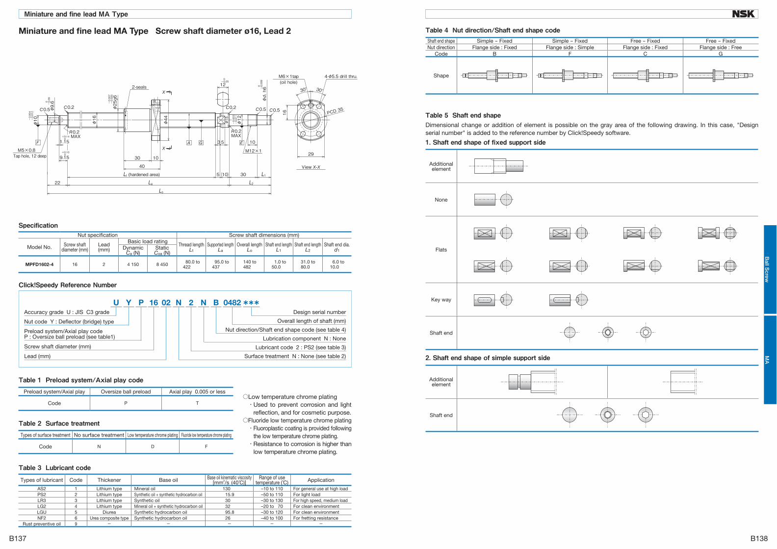
Table 2 Surface treatmentTypes of surface treatment No surface treatment Low temperature chrome plating Fluoride low temperature chrome plating
Code N D F
Table 1 Preload system/Axial play codePreload system/Axial play Oversize ball preload Axial play 0.005 or less
Code P T ○Low temperature chrome plating ・ Used to prevent corrosion and light
reflection, and for cosmetic purpose.○Fluoride low temperature chrome plating ・ Fluoroplastic coating is provided following
the low temperature chrome plating. ・ Resistance to corrosion is higher than
low temperature chrome plating.
Table 3 Lubricant codeTypes of lubricant Code Thickener Base oil Base oil kinematic viscosity
[mm2/s (40°C)]Range of use
temperature (°C) Application
AS2 1 Lithium type Mineral oil 130 –10 to 110 For general use at high loadPS2 2 Lithium type Synthetic oil + synthetic hydrocarbon oil 15.9 –50 to 110 For light loadLR3 3 Lithium type Synthetic oil 30 –30 to 130 For high speed, medium loadLG2 4 Lithium type Mineral oil + synthetic hydrocarbon oil 32 –20 to 70 For clean environmentLGU 5 Diurea Synthetic hydrocarbon oil 95.8 –30 to 120 For clean environmentNF2 6 Urea composite type Synthetic hydrocarbon oil 26 –40 to 100 For fretting resistance
Rust preventive oil 9 - - - - -
Specification
***N N2 B 0482U P 16 02Y
Surface treatment N : None (see table 2)
Design serial number
Overall length of shaft (mm)
Nut direction/Shaft end shape code (see table 4)
Lubrication component N : None
Lubricant code 2 : PS2 (see table 3)
Lead (mm)
Nut code Y : Deflector (bridge) type
Screw shaft diameter (mm)
Preload system/Axial play codeP : Oversize ball preload (see table1)
Accuracy grade U : JIS C3 grade
Click!Speedy Reference Number
Miniature and fine lead MA Type Screw shaft diameter ø16, Lead 2
Nut specification Screw shaft dimensions (mm)
Model No. Screw shaft diameter (mm)
Lead(mm)
Basic load ratingThread length
LtSupported length
LaOverall length
LoShaft end length
L1Shaft end length
L2Shaft end dia.
d1Dynamic
Ca (N)StaticCoa (N)
MPFD1602-4 16 2 4 150 8 450 80.0 to422
95.0 to437
140 to482
1.0 to50.0
31.0 to80.0
6.0 to10.0
1. Shaft end shape of fixed support side
Additional element
None
Flats
Key way
Shaft end
Dimensional change or addition of element is possible on the gray area of the following drawing. In this case, "Design serial number" is added to the reference number by Click!Speedy software.
Table 5 Shaft end shape
2. Shaft end shape of simple support side
Additional element
Shaft end
Table 4 Nut direction/Shaft end shape codeShaft end shape Simple - Fixed Simple - Fixed Free - Fixed Free - FixedNut direction Flange side : Fixed Flange side : Simple Flange side : Fixed Flange side : Free
Code B F C G
Shape
B137
Miniature and fine lead MA Type
B138
Ball S
crewM
A

Table 2 Surface treatmentTypes of surface treatment No surface treatment Low temperature chrome plating Fluoride low temperature chrome plating
Code N D F
Table 1 Preload system/Axial play codePreload system/Axial play Oversize ball preload Axial play 0.005 or less
Code P T ○Low temperature chrome plating ・ Used to prevent corrosion and light
reflection, and for cosmetic purpose.○Fluoride low temperature chrome plating ・ Fluoroplastic coating is provided following
the low temperature chrome plating. ・ Resistance to corrosion is higher than
low temperature chrome plating.
Table 3 Lubricant codeTypes of lubricant Code Thickener Base oil Base oil kinematic viscosity
[mm2/s (40°C)]Range of use
temperature (°C) Application
AS2 1 Lithium type Mineral oil 130 –10 to 110 For general use at high loadPS2 2 Lithium type Synthetic oil + synthetic hydrocarbon oil 15.9 –50 to 110 For light loadLR3 3 Lithium type Synthetic oil 30 –30 to 130 For high speed, medium loadLG2 4 Lithium type Mineral oil + synthetic hydrocarbon oil 32 –20 to 70 For clean environmentLGU 5 Diurea Synthetic hydrocarbon oil 95.8 –30 to 120 For clean environmentNF2 6 Urea composite type Synthetic hydrocarbon oil 26 –40 to 100 For fretting resistance
Rust preventive oil 9 - - - - -
Specification
***N N2 B 0482U P 16 62Y
Surface treatment N : None (see table 2)
Design serial number
Overall length of shaft (mm)
Nut direction/Shaft end shape code (see table 4)
Lubrication component N : None
Lubricant code 2 : PS2 (see table 3)
Lead (mm)
Nut code Y : Deflector (bridge) type
Screw shaft diameter (mm)
Preload system/Axial play codeP : Oversize ball preload (see table1)
Accuracy grade U : JIS C3 grade
Click!Speedy Reference Number
Miniature and fine lead MA Type Screw shaft diameter ø16, Lead 2.5
Nut specification Screw shaft dimensions (mm)
Model No. Screw shaft diameter (mm)
Lead(mm)
Basic load ratingThread length
LtSupported length
LaOverall length
LoShaft end length
L1Shaft end length
L2Shaft end dia.
d1Dynamic
Ca (N)StaticCoa (N)
MPFD1602.5-4 16 2.5 4 150 8 440 88.0 to422
103 to437
148 to482
1.0 to50.0
31.0 to80.0
6.0 to10.0
1. Shaft end shape of fixed support side
Additional element
None
Flats
Key way
Shaft end
Dimensional change or addition of element is possible on the gray area of the following drawing. In this case, "Design serial number" is added to the reference number by Click!Speedy software.
Table 5 Shaft end shape
2. Shaft end shape of simple support side
Additional element
Shaft end
Table 4 Nut direction/Shaft end shape codeShaft end shape Simple - Fixed Simple - Fixed Free - Fixed Free - FixedNut direction Flange side : Fixed Flange side : Simple Flange side : Fixed Flange side : Free
Code B F C G
Shape
B139
Miniature and fine lead MA Type
B140
Ball S
crewM
A

Table 2 Surface treatmentTypes of surface treatment No surface treatment Low temperature chrome plating Fluoride low temperature chrome plating
Code N D F
Table 1 Preload system/Axial play codePreload system/Axial play Oversize ball preload Axial play 0.005 or less
Code P T ○Low temperature chrome plating ・ Used to prevent corrosion and light
reflection, and for cosmetic purpose.○Fluoride low temperature chrome plating ・ Fluoroplastic coating is provided following
the low temperature chrome plating. ・ Resistance to corrosion is higher than
low temperature chrome plating.
Table 3 Lubricant codeTypes of lubricant Code Thickener Base oil Base oil kinematic viscosity
[mm2/s (40°C)]Range of use
temperature (°C) Application
AS2 1 Lithium type Mineral oil 130 –10 to 110 For general use at high loadPS2 2 Lithium type Synthetic oil + synthetic hydrocarbon oil 15.9 –50 to 110 For light loadLR3 3 Lithium type Synthetic oil 30 –30 to 130 For high speed, medium loadLG2 4 Lithium type Mineral oil + synthetic hydrocarbon oil 32 –20 to 70 For clean environmentLGU 5 Diurea Synthetic hydrocarbon oil 95.8 –30 to 120 For clean environmentNF2 6 Urea composite type Synthetic hydrocarbon oil 26 –40 to 100 For fretting resistance
Rust preventive oil 9 - - - - -
Specification
***N N2 B 0470U P 10 04T
Surface treatment N : None (see table 2)
Design serial number
Overall length of shaft (mm)
Nut direction/Shaft end shape code (see table 5)
Lubrication components N : None (see table 4)
Lubricant code 2 : PS2 (see table 3)
Lead (mm)
Nut code T : Ball return tube type
Screw shaft diameter (mm)
Preload system/Axial play codeP : Oversize ball preload (see table1)
Accuracy grade U : JIS C3 grade
Click!Speedy Reference Number
For small equipment FA Type Screw shaft diameter ø10, Lead 4
Nut specification Screw shaft dimensions (mm)
Model No. Screw shaft diameter (mm)
Lead(mm)
Basic load ratingThread length
LtSupported length
LaOverall length
LoShaft end length
L1Shaft end length
L2Shaft end dia.
d1Dynamic
Ca (N)StaticCoa (N)
PFT1004-2.5 10 4 2 020 2 210 68.0 to410
83.0 to425
128 to470
1.0 to25.0
31.0 to55.0
3.0 to8.0
Table 4 Lubrication componentsForm None Flange side : with K1 Opposite of flange : with K1 Both sides : with K1Code N F H K
Shape
Table 5 Nut direction/Shaft end shape codeShaft end shape Simple - Fixed Simple - Fixed Free - Fixed Free - FixedNut direction Flange side : Fixed Flange side : Simple Flange side : Fixed Flange side : Free
Code B F C G
Shape
1. Shaft end shape of fixed support side
Additional element
None
Flats
Key way
Shaft end
Dimensional change or addition of element is possible on the gray area of the following drawing. In this case, "Design serial number" is added to the reference number by Click!Speedy software.
Table 6 Shaft end shape
2. Shaft end shape of simple support side
Additional element
Shaft end
B141
For small equipment FA Type
B142
Ball S
crewFA

Table 2 Surface treatmentTypes of surface treatment No surface treatment Low temperature chrome plating Fluoride low temperature chrome plating
Code N D F
Table 1 Preload system/Axial play codePreload system/Axial play Oversize ball preload Axial play 0.005 or less
Code P T ○Low temperature chrome plating ・ Used to prevent corrosion and light
reflection, and for cosmetic purpose.○Fluoride low temperature chrome plating ・ Fluoroplastic coating is provided following
the low temperature chrome plating. ・ Resistance to corrosion is higher than
low temperature chrome plating.
Table 3 Lubricant codeTypes of lubricant Code Thickener Base oil Base oil kinematic viscosity
[mm2/s (40°C)]Range of use
temperature (°C) Application
AS2 1 Lithium type Mineral oil 130 –10 to 110 For general use at high loadPS2 2 Lithium type Synthetic oil + synthetic hydrocarbon oil 15.9 –50 to 110 For light loadLR3 3 Lithium type Synthetic oil 30 –30 to 130 For high speed, medium loadLG2 4 Lithium type Mineral oil + synthetic hydrocarbon oil 32 –20 to 70 For clean environmentLGU 5 Diurea Synthetic hydrocarbon oil 95.8 –30 to 120 For clean environmentNF2 6 Urea composite type Synthetic hydrocarbon oil 26 –40 to 100 For fretting resistance
Rust preventive oil 9 - - - - -
Specification
***N N2 B 0670U P 12 05T
Surface treatment N : None (see table 2)
Design serial number
Overall length of shaft (mm)
Nut direction/Shaft end shape code (see table 5)
Lubrication components N : None (see table 4)
Lubricant code 2 : PS2 (see table 3)
Lead (mm)
Nut code T : Ball return tube type
Screw shaft diameter (mm)
Preload system/Axial play codeP : Oversize ball preload (see table1)
Accuracy grade U : JIS C3 grade
Click!Speedy Reference Number
For small equipment FA Type Screw shaft diameter ø12, Lead 5
Nut specification Screw shaft dimensions (mm)
Model No. Screw shaft diameter (mm)
Lead(mm)
Basic load ratingThread length
LtSupported length
LaOverall length
LoShaft end length
L1Shaft end length
L2Shaft end dia.
d1Dynamic
Ca (N)StaticCoa (N)
PFT1205-2.5 12 5 2 770 3 130 80.0 to610
95.0 to625
140 to670
1.0 to25.0
31.0 to55.0
3.0 to8.0
Table 5 Nut direction/Shaft end shape codeShaft end shape Simple - Fixed Simple - Fixed Free - Fixed Free - FixedNut direction Flange side : Fixed Flange side : Simple Flange side : Fixed Flange side : Free
Code B F C G
Shape
1. Shaft end shape of fixed support side
Additional element
None
Flats
Key way
Shaft end
Dimensional change or addition of element is possible on the gray area of the following drawing. In this case, "Design serial number" is added to the reference number by Click!Speedy software.
Table 6 Shaft end shape
2. Shaft end shape of simple support side
Additional element
Shaft end
Table 4 Lubrication componentsForm None Flange side : with K1 Opposite of flange : with K1 Both sides : with K1Code N F H K
Shape
B143
For small equipment FA Type
B144
Ball S
crewFA

Table 2 Surface treatmentTypes of surface treatment No surface treatment Low temperature chrome plating Fluoride low temperature chrome plating
Code N D F
Table 1 Preload system/Axial play codePreload system/Axial play Oversize ball preload Axial play 0.005 or less
Code P T ○Low temperature chrome plating ・ Used to prevent corrosion and light
reflection, and for cosmetic purpose.○Fluoride low temperature chrome plating ・ Fluoroplastic coating is provided following
the low temperature chrome plating. ・ Resistance to corrosion is higher than
low temperature chrome plating.
Table 3 Lubricant codeTypes of lubricant Code Thickener Base oil Base oil kinematic viscosity
[mm2/s (40°C)]Range of use
temperature (°C) Application
AS2 1 Lithium type Mineral oil 130 –10 to 110 For general use at high loadPS2 2 Lithium type Synthetic oil + synthetic hydrocarbon oil 15.9 –50 to 110 For light loadLR3 3 Lithium type Synthetic oil 30 –30 to 130 For high speed, medium loadLG2 4 Lithium type Mineral oil + synthetic hydrocarbon oil 32 –20 to 70 For clean environmentLGU 5 Diurea Synthetic hydrocarbon oil 95.8 –30 to 120 For clean environmentNF2 6 Urea composite type Synthetic hydrocarbon oil 26 –40 to 100 For fretting resistance
Rust preventive oil 9 - - - - -
Specification
***N N3 B 0670P P 12 10T
Surface treatment N : None (see table 2)
Design serial number
Overall length of shaft (mm)
Nut direction/Shaft end shape code (see table 5)
Lubrication components N : None (see table 4)
Lubricant code 3 : LR3 (see table 3)
Lead (mm)
Nut code T : Ball return tube type
Screw shaft diameter (mm)
Preload system/Axial play codeP : Oversize ball preload (see table1)
Accuracy grade P : JIS C5 grade
Click!Speedy Reference Number
For small equipment FA Type Screw shaft diameter ø12, Lead 10
Nut specification Screw shaft dimensions (mm)
Model No. Screw shaft diameter (mm)
Lead(mm)
Basic load ratingThread length
LtSupported length
LaOverall length
LoShaft end length
L1Shaft end length
L2Shaft end dia.
d1Dynamic
Ca (N)StaticCoa (N)
LPFT1210-2.5 12 10 2 790 3 220 100 to610
115 to625
160 to670
1.0 to25.0
31.0 to55.0
3.0 to8.0
Table 5 Nut direction/Shaft end shape codeShaft end shape Simple - Fixed Simple - Fixed Free - Fixed Free - FixedNut direction Flange side : Fixed Flange side : Simple Flange side : Fixed Flange side : Free
Code B F C G
Shape
1. Shaft end shape of fixed support side
Additional element
None
Flats
Key way
Shaft end
Dimensional change or addition of element is possible on the gray area of the following drawing. In this case, "Design serial number" is added to the reference number by Click!Speedy software.
Table 6 Shaft end shape
2. Shaft end shape of simple support side
Additional element
Shaft end
Table 4 Lubrication componentsForm None Flange side : with K1 Opposite of flange : with K1 Both sides : with K1Code N F H K
Shape
B145
For small equipment FA Type
B146
Ball S
crewFA

Table 2 Surface treatmentTypes of surface treatment No surface treatment Low temperature chrome plating Fluoride low temperature chrome plating
Code N D F
Table 1 Preload system/Axial play codePreload system/Axial play Oversize ball preload Axial play 0.005 or less
Code P T ○Low temperature chrome plating ・ Used to prevent corrosion and light
reflection, and for cosmetic purpose.○Fluoride low temperature chrome plating ・ Fluoroplastic coating is provided following
the low temperature chrome plating. ・ Resistance to corrosion is higher than
low temperature chrome plating.
Table 3 Lubricant codeTypes of lubricant Code Thickener Base oil Base oil kinematic viscosity
[mm2/s (40°C)]Range of use
temperature (°C) Application
AS2 1 Lithium type Mineral oil 130 –10 to 110 For general use at high loadPS2 2 Lithium type Synthetic oil + synthetic hydrocarbon oil 15.9 –50 to 110 For light loadLR3 3 Lithium type Synthetic oil 30 –30 to 130 For high speed, medium loadLG2 4 Lithium type Mineral oil + synthetic hydrocarbon oil 32 –20 to 70 For clean environmentLGU 5 Diurea Synthetic hydrocarbon oil 95.8 –30 to 120 For clean environmentNF2 6 Urea composite type Synthetic hydrocarbon oil 26 –40 to 100 For fretting resistance
Rust preventive oil 9 - - - - -
Specification
***N N3 B 0782U P 14 05T
Surface treatment N : None (see table 2)
Design serial number
Overall length of shaft (mm)
Nut direction/Shaft end shape code (see table 5)
Lubrication components N : None (see table 4)
Lubricant code 3 : LR3 (see table 3)
Lead (mm)
Nut code T : Ball return tube type
Screw shaft diameter (mm)
Preload system/Axial play codeP : Oversize ball preload (see table1)
Accuracy grade U : JIS C3 grade
Click!Speedy Reference Number
For small equipment FA Type Screw shaft diameter ø14, Lead 5
Nut specification Screw shaft dimensions (mm)
Model No. Screw shaft diameter (mm)
Lead(mm)
Basic load ratingThread length
LtSupported length
LaOverall length
LoShaft end length
L1Shaft end length
L2Shaft end dia.
d1Dynamic
Ca (N)StaticCoa (N)
PFT1405-2.5 14 5 5 020 5 970 80.0 to722
95.0 to737
140 to782
1.0 to50.0
31.0 to80
6.0 to10.0
Table 5 Nut direction/Shaft end shape codeShaft end shape Simple - Fixed Simple - Fixed Free - Fixed Free - FixedNut direction Flange side : Fixed Flange side : Simple Flange side : Fixed Flange side : Free
Code B F C G
Shape
1. Shaft end shape of fixed support side
Additional element
None
Flats
Key way
Shaft end
Dimensional change or addition of element is possible on the gray area of the following drawing. In this case, "Design serial number" is added to the reference number by Click!Speedy software.
Table 6 Shaft end shape
2. Shaft end shape of simple support side
Additional element
Shaft end
Table 4 Lubrication componentsForm None Flange side : with K1 Opposite of flange : with K1 Both sides : with K1Code N F H K
Shape
B147
For small equipment FA Type
B148
Ball S
crewFA

Table 2 Surface treatmentTypes of surface treatment No surface treatment Low temperature chrome plating Fluoride low temperature chrome plating
Code N D F
Table 1 Preload system/Axial play codePreload system/Axial play Oversize ball preload Axial play 0.005 or less
Code P T ○Low temperature chrome plating ・ Used to prevent corrosion and light
reflection, and for cosmetic purpose.○Fluoride low temperature chrome plating ・ Fluoroplastic coating is provided following
the low temperature chrome plating. ・ Resistance to corrosion is higher than
low temperature chrome plating.
Table 3 Lubricant codeTypes of lubricant Code Thickener Base oil Base oil kinematic viscosity
[mm2/s (40°C)]Range of use
temperature (°C) Application
AS2 1 Lithium type Mineral oil 130 –10 to 110 For general use at high loadPS2 2 Lithium type Synthetic oil + synthetic hydrocarbon oil 15.9 –50 to 110 For light loadLR3 3 Lithium type Synthetic oil 30 –30 to 130 For high speed, medium loadLG2 4 Lithium type Mineral oil + synthetic hydrocarbon oil 32 –20 to 70 For clean environmentLGU 5 Diurea Synthetic hydrocarbon oil 95.8 –30 to 120 For clean environmentNF2 6 Urea composite type Synthetic hydrocarbon oil 26 –40 to 100 For fretting resistance
Rust preventive oil 9 - - - - -
Specification
***N N3 B 0882P P 14 08T
Surface treatment N : None (see table 2)
Design serial number
Overall length of shaft (mm)
Nut direction/Shaft end shape code (see table 5)
Lubrication components N : None (see table 4)
Lubricant code 3 : LR3 (see table 3)
Lead (mm)
Nut code T : Ball return tube type
Screw shaft diameter (mm)
Preload system/Axial play codeP : Oversize ball preload (see table1)
Accuracy grade P : JIS C5 grade
Click!Speedy Reference Number
For small equipment FA Type Screw shaft diameter ø14, Lead 8
Nut specification Screw shaft dimensions (mm)
Model No. Screw shaft diameter (mm)
Lead(mm)
Basic load ratingThread length
LtSupported length
LaOverall length
LoShaft end length
L1Shaft end length
L2Shaft end dia.
d1Dynamic
Ca (N)StaticCoa (N)
LPFT1408-2.5 14 8 4 960 5 920 92.0 to822
107 to837
152 to882
1.0 to50.0
31.0 to80.0
6.0 to10.0
Table 5 Nut direction/Shaft end shape codeShaft end shape Simple - Fixed Simple - Fixed Free - Fixed Free - FixedNut direction Flange side : Fixed Flange side : Simple Flange side : Fixed Flange side : Free
Code B F C G
Shape
1. Shaft end shape of fixed support side
Additional element
None
Flats
Key way
Shaft end
Dimensional change or addition of element is possible on the gray area of the following drawing. In this case, "Design serial number" is added to the reference number by Click!Speedy software.
Table 6 Shaft end shape
2. Shaft end shape of simple support side
Additional element
Shaft end
Table 4 Lubrication componentsForm None Flange side : with K1 Opposite of flange : with K1 Both sides : with K1Code N F H K
Shape
B149
For small equipment FA Type
B150
Ball S
crewFA

Table 2 Surface treatmentTypes of surface treatment No surface treatment Low temperature chrome plating Fluoride low temperature chrome plating
Code N D F
Table 1 Preload system/Axial play codePreload system/Axial play Oversize ball preload Axial play 0.005 or less
Code P T ○Low temperature chrome plating ・ Used to prevent corrosion and light
reflection, and for cosmetic purpose.○Fluoride low temperature chrome plating ・ Fluoroplastic coating is provided following
the low temperature chrome plating. ・ Resistance to corrosion is higher than
low temperature chrome plating.
Table 3 Lubricant codeTypes of lubricant Code Thickener Base oil Base oil kinematic viscosity
[mm2/s (40°C)]Range of use
temperature (°C) Application
AS2 1 Lithium type Mineral oil 130 –10 to 110 For general use at high loadPS2 2 Lithium type Synthetic oil + synthetic hydrocarbon oil 15.9 –50 to 110 For light loadLR3 3 Lithium type Synthetic oil 30 –30 to 130 For high speed, medium loadLG2 4 Lithium type Mineral oil + synthetic hydrocarbon oil 32 –20 to 70 For clean environmentLGU 5 Diurea Synthetic hydrocarbon oil 95.8 –30 to 120 For clean environmentNF2 6 Urea composite type Synthetic hydrocarbon oil 26 –40 to 100 For fretting resistance
Rust preventive oil 9 - - - - -
Specification
***N N3 B 1182P P 15 10T
Surface treatment N : None (see table 2)
Design serial number
Overall length of shaft (mm)
Nut direction/Shaft end shape code (see table 5)
Lubrication components N : None (see table 4)
Lubricant code 3 : LR3 (see table 3)
Lead (mm)
Nut code T : Ball return tube type
Screw shaft diameter (mm)
Preload system/Axial play codeP : Oversize ball preload (see table1)
Accuracy grade P : JIS C5 grade
Click!Speedy Reference Number
For small equipment FA Type Screw shaft diameter ø15, Lead 10
Nut specification Screw shaft dimensions (mm)
Model No. Screw shaft diameter (mm)
Lead(mm)
Basic load ratingThread length
LtSupported length
LaOverall length
LoShaft end length
L1Shaft end length
L2Shaft end dia.
d1Dynamic
Ca (N)StaticCoa (N)
LPFT1510-2.5 15 10 5 130 6 420 102 to1 122
117 to1 137
162 to1 182
1.0 to50.0
31.0 to80.0
6.0 to10.0
Table 5 Nut direction/Shaft end shape codeShaft end shape Simple - Fixed Simple - Fixed Free - Fixed Free - FixedNut direction Flange side : Fixed Flange side : Simple Flange side : Fixed Flange side : Free
Code B F C G
Shape
1. Shaft end shape of fixed support side
Additional element
None
Flats
Key way
Shaft end
Dimensional change or addition of element is possible on the gray area of the following drawing. In this case, "Design serial number" is added to the reference number by Click!Speedy software.
Table 6 Shaft end shape
2. Shaft end shape of simple support side
Additional element
Shaft end
Table 4 Lubrication componentsForm None Flange side : with K1 Opposite of flange : with K1 Both sides : with K1Code N F H K
Shape
B151
For small equipment FA Type
B152
Ball S
crewFA

Table 2 Surface treatmentTypes of surface treatment No surface treatment Low temperature chrome plating Fluoride low temperature chrome plating
Code N D F
Table 1 Preload system/Axial play codePreload system/Axial play Oversize ball preload Axial play 0.005 or less
Code P T ○Low temperature chrome plating ・ Used to prevent corrosion and light
reflection, and for cosmetic purpose.○Fluoride low temperature chrome plating ・ Fluoroplastic coating is provided following
the low temperature chrome plating. ・ Resistance to corrosion is higher than
low temperature chrome plating.
Table 3 Lubricant codeTypes of lubricant Code Thickener Base oil Base oil kinematic viscosity
[mm2/s (40°C)]Range of use
temperature (°C) Application
AS2 1 Lithium type Mineral oil 130 –10 to 110 For general use at high loadPS2 2 Lithium type Synthetic oil + synthetic hydrocarbon oil 15.9 –50 to 110 For light loadLR3 3 Lithium type Synthetic oil 30 –30 to 130 For high speed, medium loadLG2 4 Lithium type Mineral oil + synthetic hydrocarbon oil 32 –20 to 70 For clean environmentLGU 5 Diurea Synthetic hydrocarbon oil 95.8 –30 to 120 For clean environmentNF2 6 Urea composite type Synthetic hydrocarbon oil 26 –40 to 100 For fretting resistance
Rust preventive oil 9 - - - - -
Specification
***N N3 B 1185P P 15 20G
Surface treatment N : None (see table 2)
Design serial number
Overall length of shaft (mm)
Nut direction/Shaft end shape code (see table 5)
Lubrication components N : None (see table 4)
Lubricant code 3 : LR3 (see table 3)
Lead (mm)
Nut code G : End cap type
Screw shaft diameter (mm)
Preload system/Axial play codeP : Oversize ball preload (see table1)
Accuracy grade P : JIS C5 grade
Click!Speedy Reference Number
For small equipment FA Type Screw shaft diameter ø15, Lead 20
Nut specification Screw shaft dimensions (mm)
Model No. Screw shaft diameter (mm)
Lead(mm)
Basic load ratingThread length
LtSupported length
LaOverall length
LoShaft end length
L1Shaft end length
L2Shaft end dia.
d1Dynamic
Ca (N)StaticCoa (N)
UPFC1520-1.5 15 20 4 320 5 800 90.0 to1 122
108 to1 140
153 to1 185
1.0 to50.0
31.0 to80.0
6.0 to10.0
Table 4 Lubrication componentsForm None Flange side : with K1 Opposite of flange : with K1 Both sides : with K1Code N F H K
Shape
Table 5 Nut direction/Shaft end shape codeShaft end shape Simple - Fixed Simple - Fixed Free - Fixed Free - FixedNut direction Flange side : Fixed Flange side : Simple Flange side : Fixed Flange side : Free
Code B F C G
Shape
1. Shaft end shape of fixed support side
Additional element
None
Flats
Key way
Shaft end
Dimensional change or addition of element is possible on the gray area of the following drawing. In this case, "Design serial number" is added to the reference number by Click!Speedy software.
Table 6 Shaft end shape
2. Shaft end shape of simple support side
Additional element
Shaft end
B153
For small equipment FA Type
B154
Ball S
crewFA

Table 2 Surface treatmentTypes of surface treatment No surface treatment Low temperature chrome plating Fluoride low temperature chrome plating
Code N D F
Table 1 Preload system/Axial play codePreload system/Axial play Oversize ball preload Axial play 0.005 or less
Code P T ○Low temperature chrome plating ・ Used to prevent corrosion and light
reflection, and for cosmetic purpose.○Fluoride low temperature chrome plating ・ Fluoroplastic coating is provided following
the low temperature chrome plating. ・ Resistance to corrosion is higher than
low temperature chrome plating.
Table 3 Lubricant codeTypes of lubricant Code Thickener Base oil Base oil kinematic viscosity
[mm2/s (40°C)]Range of use
temperature (°C) Application
AS2 1 Lithium type Mineral oil 130 –10 to 110 For general use at high loadPS2 2 Lithium type Synthetic oil + synthetic hydrocarbon oil 15.9 –50 to 110 For light loadLR3 3 Lithium type Synthetic oil 30 –30 to 130 For high speed, medium loadLG2 4 Lithium type Mineral oil + synthetic hydrocarbon oil 32 –20 to 70 For clean environmentLGU 5 Diurea Synthetic hydrocarbon oil 95.8 –30 to 120 For clean environmentNF2 6 Urea composite type Synthetic hydrocarbon oil 26 –40 to 100 For fretting resistance
Rust preventive oil 9 - - - - -
Specification
***N N3 B 0982U P 16 05T
Surface treatment N : None (see table 2)
Design serial number
Overall length of shaft (mm)
Nut direction/Shaft end shape code (see table 5)
Lubrication components N : None (see table 4)
Lubricant code 3 : LR3 (see table 3)
Lead (mm)
Nut code T : Ball return tube type
Screw shaft diameter (mm)
Preload system/Axial play codeP : Oversize ball preload (see table1)
Accuracy grade U : JIS C3 grade
Click!Speedy Reference Number
For small equipment FA Type Screw shaft diameter ø16, Lead 5
Nut specification Screw shaft dimensions (mm)
Model No. Screw shaft diameter (mm)
Lead(mm)
Basic load ratingThread length
LtSupported length
LaOverall length
LoShaft end length
L1Shaft end length
L2Shaft end dia.
d1Dynamic
Ca (N)StaticCoa (N)
PFT1605-2.5 16 5 5 430 6 890 84.0 to922
99.0 to937
144 to982
1.0 to50.0
31.0 to80.0
6.0 to10.0
Table 5 Nut direction/Shaft end shape codeShaft end shape Simple - Fixed Simple - Fixed Free - Fixed Free - FixedNut direction Flange side : Fixed Flange side : Simple Flange side : Fixed Flange side : Free
Code B F C G
Shape
1. Shaft end shape of fixed support side
Additional element
None
Flats
Key way
Shaft end
Dimensional change or addition of element is possible on the gray area of the following drawing. In this case, "Design serial number" is added to the reference number by Click!Speedy software.
Table 6 Shaft end shape
2. Shaft end shape of simple support side
Additional element
Shaft end
Table 4 Lubrication componentsForm None Flange side : with K1 Opposite of flange : with K1 Both sides : with K1Code N F H K
Shape
B155
For small equipment FA Type
B156
Ball S
crewFA

Table 2 Surface treatmentTypes of surface treatment No surface treatment Low temperature chrome plating Fluoride low temperature chrome plating
Code N D F
Table 1 Preload system/Axial play codePreload system/Axial play Oversize ball preload Axial play 0.005 or less
Code P T ○Low temperature chrome plating ・ Used to prevent corrosion and light
reflection, and for cosmetic purpose.○Fluoride low temperature chrome plating ・ Fluoroplastic coating is provided following
the low temperature chrome plating. ・ Resistance to corrosion is higher than
low temperature chrome plating.
Table 3 Lubricant codeTypes of lubricant Code Thickener Base oil Base oil kinematic viscosity
[mm2/s (40°C)]Range of use
temperature (°C) Application
AS2 1 Lithium type Mineral oil 130 –10 to 110 For general use at high loadPS2 2 Lithium type Synthetic oil + synthetic hydrocarbon oil 15.9 –50 to 110 For light loadLR3 3 Lithium type Synthetic oil 30 –30 to 130 For high speed, medium loadLG2 4 Lithium type Mineral oil + synthetic hydrocarbon oil 32 –20 to 70 For clean environmentLGU 5 Diurea Synthetic hydrocarbon oil 95.8 –30 to 120 For clean environmentNF2 6 Urea composite type Synthetic hydrocarbon oil 26 –40 to 100 For fretting resistance
Rust preventive oil 9 - - - - -
Specification
***N N3 B 1187P P 16 16T
Surface treatment N : None (see table 2)
Design serial number
Overall length of shaft (mm)
Nut direction/Shaft end shape code (see table 5)
Lubrication components N : None (see table 4)
Lubricant code 3 : LR3 (see table 3)
Lead (mm)
Nut code T : Ball return tube type
Screw shaft diameter (mm)
Preload system/Axial play codeP : Oversize ball preload (see table1)
Accuracy grade P : JIS C5 grade
Click!Speedy Reference Number
For small equipment FA Type Screw shaft diameter ø16, Lead 16
Nut specification Screw shaft dimensions (mm)
Model No. Screw shaft diameter (mm)
Lead(mm)
Basic load ratingThread length
LtSupported length
LaOverall length
LoShaft end length
L1Shaft end length
L2Shaft end dia.
d1Dynamic
Ca (N)StaticCoa (N)
LPFT1616-1.5 16 16 4 180 5 390 112 to1 122
132 to1 142
177 to1 187
1.0 to50.0
31.0 to80.0
6.0 to10.0
Table 5 Nut direction/Shaft end shape codeShaft end shape Simple - Fixed Simple - Fixed Free - Fixed Free - FixedNut direction Flange side : Fixed Flange side : Simple Flange side : Fixed Flange side : Free
Code B F C G
Shape
1. Shaft end shape of fixed support side
Additional element
None
Flats
Key way
Shaft end
Dimensional change or addition of element is possible on the gray area of the following drawing. In this case, "Design serial number" is added to the reference number by Click!Speedy software.
Table 6 Shaft end shape
2. Shaft end shape of simple support side
Additional element
Shaft end
Table 4 Lubrication componentsForm None Flange side : with K1 Opposite of flange : with K1 Both sides : with K1Code N F H K
Shape
B157
For small equipment FA Type
B158
Ball S
crewFA

Table 2 Surface treatmentTypes of surface treatment No surface treatment Low temperature chrome plating Fluoride low temperature chrome plating
Code N D F
Table 1 Preload system/Axial play codePreload system/Axial play Oversize ball preload Axial play 0.005 or less
Code P T ○Low temperature chrome plating ・ Used to prevent corrosion and light
reflection, and for cosmetic purpose.○Fluoride low temperature chrome plating ・ Fluoroplastic coating is provided following
the low temperature chrome plating. ・ Resistance to corrosion is higher than
low temperature chrome plating.
Table 3 Lubricant codeTypes of lubricant Code Thickener Base oil Base oil kinematic viscosity
[mm2/s (40°C)]Range of use
temperature (°C) Application
AS2 1 Lithium type Mineral oil 130 –10 to 110 For general use at high loadPS2 2 Lithium type Synthetic oil + synthetic hydrocarbon oil 15.9 –50 to 110 For light loadLR3 3 Lithium type Synthetic oil 30 –30 to 130 For high speed, medium loadLG2 4 Lithium type Mineral oil + synthetic hydrocarbon oil 32 –20 to 70 For clean environmentLGU 5 Diurea Synthetic hydrocarbon oil 95.8 –30 to 120 For clean environmentNF2 6 Urea composite type Synthetic hydrocarbon oil 26 –40 to 100 For fretting resistance
Rust preventive oil 9 - - - - -
Specification
***N N3 B 1389P P 16 32G
Surface treatment N : None (see table 2)
Design serial number
Overall length of shaft (mm)
Nut direction/Shaft end shape code (see table 5)
Lubrication components N : None (see table 4)
Lubricant code 3 : LR3 (see table 3)
Lead (mm)
Nut code G : End cap type
Screw shaft diameter (mm)
Preload system/Axial play codeP : Oversize ball preload (see table1)
Accuracy grade P : JIS C5 grade
Click!Speedy Reference Number
For small equipment FA Type Screw shaft diameter ø16, Lead 32
Nut specification Screw shaft dimensions (mm)
Model No. Screw shaft diameter (mm)
Lead(mm)
Basic load ratingThread length
LtSupported length
LaOverall length
LoShaft end length
L1Shaft end length
L2Shaft end dia.
d1Dynamic
Ca (N)StaticCoa (N)
UPFC1632-1 16 32 4 800 7 510 68.0 to1 322
90.0 to1 344
135 to1 389
1.0 to50.0
31.0 to80.0
6.0 to10.0
Table 5 Nut direction/Shaft end shape codeShaft end shape Simple - Fixed Simple - Fixed Free - Fixed Free - FixedNut direction Flange side : Fixed Flange side : Simple Flange side : Fixed Flange side : Free
Code B F C G
Shape
1. Shaft end shape of fixed support side
Additional element
None
Flats
Key way
Shaft end
Dimensional change or addition of element is possible on the gray area of the following drawing. In this case, "Design serial number" is added to the reference number by Click!Speedy software.
Table 6 Shaft end shape
2. Shaft end shape of simple support side
Additional element
Shaft end
Table 4 Lubrication componentsForm None Flange side : with K1 Opposite of flange : with K1 Both sides : with K1Code N F H K
Shape
B159
For small equipment FA Type
B160
Ball S
crewFA

Table 2 Surface treatmentTypes of surface treatment No surface treatment Low temperature chrome plating Fluoride low temperature chrome plating
Code N D F
Table 1 Preload system/Axial play codePreload system/Axial play Oversize ball preload Axial play 0.005 or less
Code P T ○Low temperature chrome plating ・ Used to prevent corrosion and light
reflection, and for cosmetic purpose.○Fluoride low temperature chrome plating ・ Fluoroplastic coating is provided following
the low temperature chrome plating. ・ Resistance to corrosion is higher than
low temperature chrome plating.
Table 3 Lubricant codeTypes of lubricant Code Thickener Base oil Base oil kinematic viscosity
[mm2/s (40°C)]Range of use
temperature (°C) Application
AS2 1 Lithium type Mineral oil 130 –10 to 110 For general use at high loadPS2 2 Lithium type Synthetic oil + synthetic hydrocarbon oil 15.9 –50 to 110 For light loadLR3 3 Lithium type Synthetic oil 30 –30 to 130 For high speed, medium loadLG2 4 Lithium type Mineral oil + synthetic hydrocarbon oil 32 –20 to 70 For clean environmentLGU 5 Diurea Synthetic hydrocarbon oil 95.8 –30 to 120 For clean environmentNF2 6 Urea composite type Synthetic hydrocarbon oil 26 –40 to 100 For fretting resistance
Rust preventive oil 9 - - - - -
Specification
***N N3 B 1410P P 20 10T
Surface treatment N : None (see table 2)
Design serial number
Overall length of shaft (mm)
Nut direction/Shaft end shape code (see table 5)
Lubrication components N : None (see table 4)
Lubricant code 3 : LR3 (see table 3)
Lead (mm)
Nut code T : Ball return tube type
Screw shaft diameter (mm)
Preload system/Axial play codeP : Oversize ball preload (see table1)
Accuracy grade P : JIS C5 grade
Click!Speedy Reference Number
For small equipment FA Type Screw shaft diameter ø20, Lead 10
Nut specification Screw shaft dimensions (mm)
Model No. Screw shaft diameter (mm)
Lead(mm)
Basic load ratingThread length
LtSupported length
LaOverall length
LoShaft end length
L1Shaft end length
L2Shaft end dia.
d1Dynamic
Ca (N)StaticCoa (N)
LPFT2010-2.5 20 10 8 350 11 000 108 to1 325
133 to1 350
193 to1 410
1.0 to60.0
41.0 to100
6.0 to12.0
Table 5 Nut direction/Shaft end shape codeShaft end shape Simple - Fixed Simple - Fixed Free - Fixed Free - FixedNut direction Flange side : Fixed Flange side : Simple Flange side : Fixed Flange side : Free
Code B F C G
Shape
1. Shaft end shape of fixed support side
Additional element
None
Flats
Key way
Shaft end
Dimensional change or addition of element is possible on the gray area of the following drawing. In this case, "Design serial number" is added to the reference number by Click!Speedy software.
Table 6 Shaft end shape
2. Shaft end shape of simple support side
Additional element
Shaft end
Table 4 Lubrication componentsForm None Flange side : with K1 Opposite of flange : with K1 Both sides : with K1Code N F H K
Shape
B161
For small equipment FA Type
B162
Ball S
crewFA

Table 2 Surface treatmentTypes of surface treatment No surface treatment Low temperature chrome plating Fluoride low temperature chrome plating
Code N D F
Table 1 Preload system/Axial play codePreload system/Axial play Oversize ball preload Axial play 0.005 or less
Code P T ○Low temperature chrome plating ・ Used to prevent corrosion and light
reflection, and for cosmetic purpose.○Fluoride low temperature chrome plating ・ Fluoroplastic coating is provided following
the low temperature chrome plating. ・ Resistance to corrosion is higher than
low temperature chrome plating.
Table 3 Lubricant codeTypes of lubricant Code Thickener Base oil Base oil kinematic viscosity
[mm2/s (40°C)]Range of use
temperature (°C) Application
AS2 1 Lithium type Mineral oil 130 –10 to 110 For general use at high loadPS2 2 Lithium type Synthetic oil + synthetic hydrocarbon oil 15.9 –50 to 110 For light loadLR3 3 Lithium type Synthetic oil 30 –30 to 130 For high speed, medium loadLG2 4 Lithium type Mineral oil + synthetic hydrocarbon oil 32 –20 to 70 For clean environmentLGU 5 Diurea Synthetic hydrocarbon oil 95.8 –30 to 120 For clean environmentNF2 6 Urea composite type Synthetic hydrocarbon oil 26 –40 to 100 For fretting resistance
Rust preventive oil 9 - - - - -
Specification
***N N3 B 1910P P 20 20T
Surface treatment N : None (see table 2)
Design serial number
Overall length of shaft (mm)
Nut direction/Shaft end shape code (see table 5)
Lubrication components N : None (see table 4)
Lubricant code 3 : LR3 (see table 3)
Lead (mm)
Nut code T : Ball return tube type
Screw shaft diameter (mm)
Preload system/Axial play codeP : Oversize ball preload (see table1)
Accuracy grade P : JIS C5 grade
Click!Speedy Reference Number
For small equipment FA Type Screw shaft diameter ø20, Lead 20
Nut specification Screw shaft dimensions (mm)
Model No. Screw shaft diameter (mm)
Lead(mm)
Basic load ratingThread length
LtSupported length
LaOverall length
LoShaft end length
L1Shaft end length
L2Shaft end dia.
d1Dynamic
Ca (N)StaticCoa (N)
LPFT2020-1.5 20 20 6 250 8 760 126 to1 825
151 to1 850
211 to1 910
1.0 to60.0
41.0 to100
6.0 to12.0
Table 5 Nut direction/Shaft end shape codeShaft end shape Simple - Fixed Simple - Fixed Free - Fixed Free - FixedNut direction Flange side : Fixed Flange side : Simple Flange side : Fixed Flange side : Free
Code B F C G
Shape
1. Shaft end shape of fixed support side
Additional element
None
Flats
Key way
Shaft end
Dimensional change or addition of element is possible on the gray area of the following drawing. In this case, "Design serial number" is added to the reference number by Click!Speedy software.
Table 6 Shaft end shape
2. Shaft end shape of simple support side
Additional element
Shaft end
Table 4 Lubrication componentsForm None Flange side : with K1 Opposite of flange : with K1 Both sides : with K1Code N F H K
Shape
B163
For small equipment FA Type
B164
Ball S
crewFA

Table 2 Surface treatmentTypes of surface treatment No surface treatment Low temperature chrome plating Fluoride low temperature chrome plating
Code N D F
Table 1 Preload system/Axial play codePreload system/Axial play Oversize ball preload Axial play 0.005 or less
Code P T ○Low temperature chrome plating ・ Used to prevent corrosion and light
reflection, and for cosmetic purpose.○Fluoride low temperature chrome plating ・ Fluoroplastic coating is provided following
the low temperature chrome plating. ・ Resistance to corrosion is higher than
low temperature chrome plating.
Table 3 Lubricant codeTypes of lubricant Code Thickener Base oil Base oil kinematic viscosity
[mm2/s (40°C)]Range of use
temperature (°C) Application
AS2 1 Lithium type Mineral oil 130 –10 to 110 For general use at high loadPS2 2 Lithium type Synthetic oil + synthetic hydrocarbon oil 15.9 –50 to 110 For light loadLR3 3 Lithium type Synthetic oil 30 –30 to 130 For high speed, medium loadLG2 4 Lithium type Mineral oil + synthetic hydrocarbon oil 32 –20 to 70 For clean environmentLGU 5 Diurea Synthetic hydrocarbon oil 95.8 –30 to 120 For clean environmentNF2 6 Urea composite type Synthetic hydrocarbon oil 26 –40 to 100 For fretting resistance
Rust preventive oil 9 - - - - -
Specification
***N N3 B 2314P P 20 40G
Surface treatment N : None (see table 2)
Design serial number
Overall length of shaft (mm)
Nut direction/Shaft end shape code (see table 5)
Lubrication components N : None (see table 4)
Lubricant code 3 : LR3 (see table 3)
Lead (mm)
Nut code G : End cap type
Screw shaft diameter (mm)
Preload system/Axial play codeP : Oversize ball preload (see table1)
Accuracy grade P : JIS C5 grade
Click!Speedy Reference Number
For small equipment FA Type Screw shaft diameter ø20, Lead 40
Nut specification Screw shaft dimensions (mm)
Model No. Screw shaft diameter (mm)
Lead(mm)
Basic load ratingThread length
LtSupported length
LaOverall length
LoShaft end length
L1Shaft end length
L2Shaft end dia.
d1Dynamic
Ca (N)StaticCoa (N)
UPFC2040-1 20 40 5 410 9 360 82.0 to2 225
111 to2 254
171 to2 314
1.0 to60.0
41.0 to100
6.0 to12.0
Table 5 Nut direction/Shaft end shape codeShaft end shape Simple - Fixed Simple - Fixed Free - Fixed Free - FixedNut direction Flange side : Fixed Flange side : Simple Flange side : Fixed Flange side : Free
Code B F C G
Shape
1. Shaft end shape of fixed support side
Additional element
None
Flats
Key way
Shaft end
Dimensional change or addition of element is possible on the gray area of the following drawing. In this case, "Design serial number" is added to the reference number by Click!Speedy software.
Table 6 Shaft end shape
2. Shaft end shape of simple support side
Additional element
Shaft end
Table 4 Lubrication componentsForm None Flange side : with K1 Opposite of flange : with K1 Both sides : with K1Code N F H K
Shape
B165
For small equipment FA Type
B166
Ball S
crewFA

Types of lubricant Code Thickener Base oil Base oil kinematic viscosity[mm2/s (40°C)]
Range of use temperature (°C) Application
AS2 1 Lithium type Mineral oil 130 –10 to 110 For general use at high loadPS2 2 Lithium type Synthetic oil + synthetic hydrocarbon oil 15.9 –50 to 110 For light loadLR3 3 Lithium type Synthetic oil 30 –30 to 130 For high speed, medium loadLG2 4 Lithium type Mineral oil + synthetic hydrocarbon oil 32 –20 to 70 For clean environmentLGU 5 Diurea Synthetic hydrocarbon oil 95.8 –30 to 120 For clean environmentNF2 6 Urea composite type Synthetic hydrocarbon oil 26 –40 to 100 For fretting resistance
Rust preventive oil 9 - - - - -
○Low temperature chrome plating ・ Used to prevent corrosion and light
reflection, and for cosmetic purpose.○Fluoride low temperature chrome plating ・ Fluoroplastic coating is provided following
the low temperature chrome plating. ・ Resistance to corrosion is higher than
low temperature chrome plating.
Table 3 Lubricant code
Table 2 Surface treatmentTypes of surface treatment No surface treatment Low temperature chrome plating Fluoride low temperature chrome plating
Code N D F
Table 1 Preload system/Axial play codePreload system/Axial play Oversize ball preload Axial play 0.005 or less
Code P T
Specification
***N N3 B 2363P P 25 20T
Surface treatment N : None (see table 2)
Design serial number
Overall length of shaft (mm)
Nut direction/Shaft end shape code (see table 5)
Lubrication components N : None (see table 4)
Lubricant code 3 : LR3 (see table 3)
Lead (mm)
Nut code T : Ball return tube type
Screw shaft diameter (mm)
Preload system/Axial play codeP : Oversize ball preload (see table1)
Accuracy grade P : JIS C5 grade
Click!Speedy Reference Number
For small equipment FA Type Screw shaft diameter ø25, Lead 20
Nut specification Screw shaft dimensions (mm)
Model No. Screw shaft diameter (mm)
Lead(mm)
Basic load ratingShaft end
shapeThread length
Lt Supported length
La Overall length
Lo Shaft end length
L1 Shaft end length
L2 Shaft end dia.
d1DynamicCa (N)
Static Coa (N)
LPFT2520-2.5 25 20 11 700 16 300
Simple 192 to2 234
222 to2 264
321 to2 363
1.0 to75.0
54.0 to128
8.0 to15.0
Fixed 192 to2 200
222 to2 230
355 to2 363
1.0 to75.0
54.0 to128
8.0 to15.0
Table 5 Nut direction/Shaft end shape codeShaft end shape Simple - Fixed Simple - Fixed Free - Fixed Free - Fixed Fixed - Fixed Fixed - FixedNut direction Flange side : Fixed Flange side : Simple Flange side : Fixed Flange side : Free Flange side : Drive side Flange side : Opposite to drive side
Code B F C G A E
Shape
1. Shaft end shape of fixed support side
Additional element
None
Flats
Key way
Shaft end
Dimensional change or addition of element is possible on the gray area of the following drawing. In this case, "Design serial number" is added to the reference number by Click!Speedy software.
Table 6 Shaft end shape
2. Shaft end shape of simple support side
Additional element
Shaft end
Table 4 Lubrication componentsForm None Flange side : with K1 Opposite of flange : with K1 Both sides : with K1Code N F H K
Shape
Simple
Fixed
B167
For small equipment FA Type
B168
Ball S
crewFA

Types of lubricant Code Thickener Base oil Base oil kinematic viscosity[mm2/s (40°C)]
Range of use temperature (°C) Application
AS2 1 Lithium type Mineral oil 130 –10 to 110 For general use at high loadPS2 2 Lithium type Synthetic oil + synthetic hydrocarbon oil 15.9 –50 to 110 For light loadLR3 3 Lithium type Synthetic oil 30 –30 to 130 For high speed, medium loadLG2 4 Lithium type Mineral oil + synthetic hydrocarbon oil 32 –20 to 70 For clean environmentLGU 5 Diurea Synthetic hydrocarbon oil 95.8 –30 to 120 For clean environmentNF2 6 Urea composite type Synthetic hydrocarbon oil 26 –40 to 100 For fretting resistance
Rust preventive oil 9 - - - - -
○Low temperature chrome plating ・ Used to prevent corrosion and light
reflection, and for cosmetic purpose.○Fluoride low temperature chrome plating ・ Fluoroplastic coating is provided following
the low temperature chrome plating. ・ Resistance to corrosion is higher than
low temperature chrome plating.
Table 3 Lubricant code
Table 2 Surface treatmentTypes of surface treatment No surface treatment Low temperature chrome plating Fluoride low temperature chrome plating
Code N D F
Table 1 Preload system/Axial play codePreload system/Axial play Oversize ball preload Axial play 0.005 or less
Code P T
Specification
***N N3 B 2363P P 25 25T
Surface treatment N : None (see table 2)
Design serial number
Overall length of shaft (mm)
Nut direction/Shaft end shape code (see table 5)
Lubrication components N : None (see table 4)
Lubricant code 3 : LR3 (see table 3)
Lead (mm)
Nut code T : Ball return tube type
Screw shaft diameter (mm)
Preload system/Axial play codeP : Oversize ball preload (see table1)
Accuracy grade P : JIS C5 grade
Click!Speedy Reference Number
For small equipment FA Type Screw shaft diameter ø25, Lead 25
Nut specification Screw shaft dimensions (mm)
Model No. Screw shaft diameter (mm)
Lead(mm)
Basic load ratingShaft end
shapeThread length
Lt Supported length
La Overall length
Lo Shaft end length
L1 Shaft end length
L2 Shaft end dia.
d1DynamicCa (N)
Static Coa (N)
LPFT2525-1.5 25 25 8 970 13 100
Simple 180 to2 234
210 to2 264
309 to2 363
1.0 to75.0
54 to128
8.0 to15.0
Fixed 180 to2 200
210 to2 230
343 to2 363
1.0 to75.0
54 to128
8.0 to15.0
Table 5 Nut direction/Shaft end shape codeShaft end shape Simple - Fixed Simple - Fixed Free - Fixed Free - Fixed Fixed - Fixed Fixed - FixedNut direction Flange side : Fixed Flange side : Simple Flange side : Fixed Flange side : Free Flange side : Drive side Flange side : Opposite to drive side
Code B F C G A E
Shape
1. Shaft end shape of fixed support side
Additional element
None
Flats
Key way
Shaft end
Dimensional change or addition of element is possible on the gray area of the following drawing. In this case, "Design serial number" is added to the reference number by Click!Speedy software.
Table 6 Shaft end shape
2. Shaft end shape of simple support side
Additional element
Shaft end
Table 4 Lubrication componentsForm None Flange side : with K1 Opposite of flange : with K1 Both sides : with K1Code N F H K
Shape
Simple
Fixed
B169
For small equipment FA Type
B170
Ball S
crewFA

Types of lubricant Code Thickener Base oil Base oil kinematic viscosity[mm2/s (40°C)]
Range of use temperature (°C) Application
AS2 1 Lithium type Mineral oil 130 –10 to 110 For general use at high loadPS2 2 Lithium type Synthetic oil + synthetic hydrocarbon oil 15.9 –50 to 110 For light loadLR3 3 Lithium type Synthetic oil 30 –30 to 130 For high speed, medium loadLG2 4 Lithium type Mineral oil + synthetic hydrocarbon oil 32 –20 to 70 For clean environmentLGU 5 Diurea Synthetic hydrocarbon oil 95.8 –30 to 120 For clean environmentNF2 6 Urea composite type Synthetic hydrocarbon oil 26 –40 to 100 For fretting resistance
Rust preventive oil 9 - - - - -
Table 3 Lubricant code
Table 1 Preload system/Axial play codePreload system/Axial play Oversize ball preload Axial play 0.005 or less
Code P T
Table 2 Surface treatmentTypes of surface treatment No surface treatment Low temperature chrome plating Fluoride low temperature chrome plating
Code N D F
○Low temperature chrome plating ・ Used to prevent corrosion and light
reflection, and for cosmetic purpose.○Fluoride low temperature chrome plating ・ Fluoroplastic coating is provided following
the low temperature chrome plating. ・ Resistance to corrosion is higher than
low temperature chrome plating.
Specification
***N N3 B 2369P P 25 50G
Surface treatment N : None (see table 2)
Design serial number
Overall length of shaft (mm)
Nut direction/Shaft end shape code (see table 5)
Lubrication components N : None (see table 4)
Lubricant code 3 : LR3 (see table 3)
Lead (mm)
Nut code G : End cap type
Screw shaft diameter (mm)
Preload system/Axial play codeP : Oversize ball preload (see table1)
Accuracy grade P : JIS C5 grade
Click!Speedy Reference Number
For small equipment FA Type Screw shaft diameter ø25, Lead 50
Nut specification Screw shaft dimensions (mm)
Model No. Screw shaft diameter (mm)
Lead(mm)
Basic load ratingShaft end
shapeThread length
Lt Supported length
La Overall length
Lo Shaft end length
L1 Shaft end length
L2 Shaft end dia.
d1DynamicCa (N)
Static Coa (N)
UPFC2550-1 25 50 8 090 14 600
Simple 100 to2 234
136 to2 270
235 to2 369
1.0 to75.0
54 to128
8.0 to15.0
Fixed 100 to2 200
136 to2 236
269 to2 369
1.0 to75.0
54 to128
8.0 to15.0
Table 5 Nut direction/Shaft end shape codeShaft end shape Simple - Fixed Simple - Fixed Free - Fixed Free - Fixed Fixed - Fixed Fixed - FixedNut direction Flange side : Fixed Flange side : Simple Flange side : Fixed Flange side : Free Flange side : Drive side Flange side : Opposite to drive side
Code B F C G A E
Shape
1. Shaft end shape of fixed support side
Additional element
None
Flats
Key way
Shaft end
Dimensional change or addition of element is possible on the gray area of the following drawing. In this case, "Design serial number" is added to the reference number by Click!Speedy software.
Table 6 Shaft end shape
2. Shaft end shape of simple support side
Additional element
Shaft end
Table 4 Lubrication componentsForm None Flange side : with K1 Opposite of flange : with K1 Both sides : with K1Code N F H K
Shape
Simple
Fixed
B171
For small equipment FA Type
B172
Ball S
crewFA

Types of lubricant Code Thickener Base oil Base oil kinematic viscosity[mm2/s (40°C)]
Range of use temperature (°C) Application
AS2 1 Lithium type Mineral oil 130 –10 to 110 For general use at high loadPS2 2 Lithium type Synthetic oil + synthetic hydrocarbon oil 15.9 –50 to 110 For light loadLR3 3 Lithium type Synthetic oil 30 –30 to 130 For high speed, medium loadLG2 4 Lithium type Mineral oil + synthetic hydrocarbon oil 32 –20 to 70 For clean environmentLGU 5 Diurea Synthetic hydrocarbon oil 95.8 –30 to 120 For clean environmentNF2 6 Urea composite type Synthetic hydrocarbon oil 26 –40 to 100 For fretting resistance
Rust preventive oil 9 - - - - -
○Low temperature chrome plating ・ Used to prevent corrosion and light
reflection, and for cosmetic purpose.○Fluoride low temperature chrome plating ・ Fluoroplastic coating is provided following
the low temperature chrome plating. ・ Resistance to corrosion is higher than
low temperature chrome plating.
Table 3 Lubricant code
Table 2 Surface treatmentTypes of surface treatment No surface treatment Low temperature chrome plating Fluoride low temperature chrome plating
Code N D F
Table 1 Preload system/Axial play codePreload system/Axial play Oversize ball preload Axial play 0.005 or less
Code P T
Specification
***N N3 B 2996P P 32 25T
Surface treatment N : None (see table 2)
Design serial number
Overall length of shaft (mm)
Nut direction/Shaft end shape code (see table 5)
Lubrication components N : None (see table 4)
Lubricant code 3 : LR3 (see table 3)
Lead (mm)
Nut code T : Ball return tube type
Screw shaft diameter (mm)
Preload system/Axial play codeP : Oversize ball preload (see table1)
Accuracy grade P : JIS C5 grade
Click!Speedy Reference Number
For small equipment FA Type Screw shaft diameter ø32, Lead 25
Nut specification Screw shaft dimensions (mm)
Model No. Screw shaft diameter (mm)
Lead(mm)
Basic load ratingShaft end
shapeThread length
Lt Supported length
La Overall length
Lo Shaft end length
L1 Shaft end length
L2 Shaft end dia.
d1DynamicCa (N)
Static Coa (N)
LPFT3225-2.5 32 25 12 900 21 100
Simple 234 to2 842
273 to2 881
388 to2 996
1.0 to100
63 to162
8.0 to20.0
Fixed 234 to2 800
273 to2 839
430 to2 996
1.0 to100
63 to162
8.0 to20.0
Table 5 Nut direction/Shaft end shape codeShaft end shape Simple - Fixed Simple - Fixed Free - Fixed Free - Fixed Fixed - Fixed Fixed - FixedNut direction Flange side : Fixed Flange side : Simple Flange side : Fixed Flange side : Free Flange side : Drive side Flange side : Opposite to drive side
Code B F C G A E
Shape
1. Shaft end shape of fixed support side
Additional element
None
Flats
Key way
Shaft end
Dimensional change or addition of element is possible on the gray area of the following drawing. In this case, "Design serial number" is added to the reference number by Click!Speedy software.
Table 6 Shaft end shape
2. Shaft end shape of simple support side
Additional element
Shaft end
Table 4 Lubrication componentsForm None Flange side : with K1 Opposite of flange : with K1 Both sides : with K1Code N F H K
Shape
Simple
Fixed
B173
For small equipment FA Type
B174
Ball S
crewFA

Types of lubricant Code Thickener Base oil Base oil kinematic viscosity[mm2/s (40°C)]
Range of use temperature (°C) Application
AS2 1 Lithium type Mineral oil 130 –10 to 110 For general use at high loadPS2 2 Lithium type Synthetic oil + synthetic hydrocarbon oil 15.9 –50 to 110 For light loadLR3 3 Lithium type Synthetic oil 30 –30 to 130 For high speed, medium loadLG2 4 Lithium type Mineral oil + synthetic hydrocarbon oil 32 –20 to 70 For clean environmentLGU 5 Diurea Synthetic hydrocarbon oil 95.8 –30 to 120 For clean environmentNF2 6 Urea composite type Synthetic hydrocarbon oil 26 –40 to 100 For fretting resistance
Rust preventive oil 9 - - - - -
○Low temperature chrome plating ・ Used to prevent corrosion and light
reflection, and for cosmetic purpose.○Fluoride low temperature chrome plating ・ Fluoroplastic coating is provided following
the low temperature chrome plating. ・ Resistance to corrosion is higher than
low temperature chrome plating.
Table 3 Lubricant code
Table 2 Surface treatmentTypes of surface treatment No surface treatment Low temperature chrome plating Fluoride low temperature chrome plating
Code N D F
Table 1 Preload system/Axial play codePreload system/Axial play Oversize ball preload Axial play 0.005 or less
Code P T
Specification
***N N3 B 2996P P 32 32T
Surface treatment N : None (see table 2)
Design serial number
Overall length of shaft (mm)
Nut direction/Shaft end shape code (see table 5)
Lubrication components N : None (see table 4)
Lubricant code 3 : LR3 (see table 3)
Lead (mm)
Nut code T : Ball return tube type
Screw shaft diameter (mm)
Preload system/Axial play codeP : Oversize ball preload (see table1)
Accuracy grade P : JIS C5 grade
Click!Speedy Reference Number
For small equipment FA Type Screw shaft diameter ø32, Lead 32
Nut specification Screw shaft dimensions (mm)
Model No. Screw shaft diameter (mm)
Lead(mm)
Basic load ratingShaft end
shapeThread length
Lt Supported length
La Overall length
Lo Shaft end length
L1 Shaft end length
L2 Shaft end dia.
d1DynamicCa (N)
Static Coa (N)
LPFT3232-1.5 32 32 10 100 16 800
Simple 218 to2 842
257 to2 881
372 to2 996
1.0 to100
63 to162
8.0 to20.0
Fixed 218 to2 800
257 to2 839
414 to2 996
1.0 to100
63 to162
8.0 to20.0
Table 5 Nut direction/Shaft end shape codeShaft end shape Simple - Fixed Simple - Fixed Free - Fixed Free - Fixed Fixed - Fixed Fixed - FixedNut direction Flange side : Fixed Flange side : Simple Flange side : Fixed Flange side : Free Flange side : Drive side Flange side : Opposite to drive side
Code B F C G A E
Shape
1. Shaft end shape of fixed support side
Additional element
None
Flats
Key way
Shaft end
Dimensional change or addition of element is possible on the gray area of the following drawing. In this case, "Design serial number" is added to the reference number by Click!Speedy software.
Table 6 Shaft end shape
2. Shaft end shape of simple support side
Additional element
Shaft end
Table 4 Lubrication componentsForm None Flange side : with K1 Opposite of flange : with K1 Both sides : with K1Code N F H K
Shape
Simple
Fixed
B175
For small equipment FA Type
B176
Ball S
crewFA

○Low temperature chrome plating ・ Used to prevent corrosion and light
reflection, and for cosmetic purpose.○Fluoride low temperature chrome plating ・ Fluoroplastic coating is provided following
the low temperature chrome plating. ・ Resistance to corrosion is higher than
low temperature chrome plating.
Table 3 Lubricant codeTypes of lubricant Code Thickener Base oil Base oil kinematic viscosity
[mm2/s (40°C)]Range of use
temperature (°C) Application
AS2 1 Lithium type Mineral oil 130 –10 to 110 For general use at high load
LR3 3 Lithium type Synthetic oil 30 –30 to 130 For high speed, medium load
LG2 4 Lithium type Mineral oil + synthetic hydrocarbon oil 32 –20 to 70 For clean environment
LGU 5 Diurea Synthetic hydrocarbon oil 95.8 –30 to 120 For clean environment
NF2 6 Urea composite type Synthetic hydrocarbon oil 26 –40 to 100 For fretting resistance
Rust preventive oil 9 - - - - -
Table 2 Surface treatmentTypes of surface treatment No surface treatment Low temperature chrome plating Fluoride low temperature chrome plating
Code N D F
Table 1 Preload system/Axial play codePreload system/Axial play Oversize ball preload Axial play 0.005 or less
Code P T
Specification
***N N9 B 0910P P 20 04T
Surface treatment N : None (see table 2)
Design serial number
Overall length of shaft (mm)
Nut direction/Shaft end shape code (see table 5)
Lubrication components N : None (see table 4)
Lubricant code 9 : Rust preventive oil (see table 3)
Lead (mm)
Nut code T : Ball return tube type
Screw shaft diameter (mm)
Preload system/Axial play codeP : Oversize ball preload (see table1)
Accuracy grade P : JIS C5 grade
Click!Speedy Reference Number
For machine tools SA Type Screw shaft diameter ø20, Lead 4
Nut specification Screw shaft dimensions (mm)
Model No. Screw shaft diameter (mm)
Lead(mm)
Basic load ratingThread length
LtSupported length
LaOverall length
LoShaft end length
L1Shaft end length
L2Shaft end dia.
d1Dynamic
Ca (N)StaticCoa (N)
PFT2004-5 20 4 6 550 10 900 98.0 to825
123 to850
183 to910
1.0 to60.0
41.0 to100
6.0 to12.0
2. Shaft end shape of simple support side
Additional element
Shaft end
Initial setting
Table 5 Nut direction/Shaft end shape codeShaft end shape Simple - Fixed Simple - Fixed Free - Fixed Free - FixedNut direction Flange side : Fixed Flange side : Simple Flange side : Fixed Flange side : Free
Code B F C G
Shape
1. Shaft end shape of fixed support side
Additional element
None
Flats
Key way
Shaft end
Dimensional change or addition of element is possible on the gray area of the following drawing. In this case, "Design serial number" is added to the reference number by Click!Speedy software.
Table 6 Shaft end shape
Table 4 Lubrication componentsForm None Flange side : with K1 Opposite of flange : with K1 Both sides : with K1Code N F H K
Shape
B177
For machine tools SA Type
B178
Ball S
crewS
A

○Low temperature chrome plating ・ Used to prevent corrosion and light
reflection, and for cosmetic purpose.○Fluoride low temperature chrome plating ・ Fluoroplastic coating is provided following
the low temperature chrome plating. ・ Resistance to corrosion is higher than
low temperature chrome plating.
Table 3 Lubricant codeTypes of lubricant Code Thickener Base oil Base oil kinematic viscosity
[mm2/s (40°C)]Range of use
temperature (°C) Application
AS2 1 Lithium type Mineral oil 130 –10 to 110 For general use at high load
LR3 3 Lithium type Synthetic oil 30 –30 to 130 For high speed, medium load
LG2 4 Lithium type Mineral oil + synthetic hydrocarbon oil 32 –20 to 70 For clean environment
LGU 5 Diurea Synthetic hydrocarbon oil 95.8 –30 to 120 For clean environment
NF2 6 Urea composite type Synthetic hydrocarbon oil 26 –40 to 100 For fretting resistance
Rust preventive oil 9 - - - - -
Table 2 Surface treatmentTypes of surface treatment No surface treatment Low temperature chrome plating Fluoride low temperature chrome plating
Code N D F
Table 1 Preload system/Axial play codePreload system/Axial play Oversize ball preload Axial play 0.005 or less
Code P T
Specification
***N N9 B 1110P P 20 05T
Surface treatment N : None (see table 2)
Design serial number
Overall length of shaft (mm)
Nut direction/Shaft end shape code (see table 5)
Lubrication components N : None (see table 4)
Lubricant code 9 : Rust preventive oil (see table 3)
Lead (mm)
Nut code T : Ball return tube type
Screw shaft diameter (mm)
Preload system/Axial play codeP : Oversize ball preload (see table1)
Accuracy grade P : JIS C5 grade
Click!Speedy Reference Number
For machine tools SA Type Screw shaft diameter ø20, Lead 5
Nut specification Screw shaft dimensions (mm)
Model No. Screw shaft diameter (mm)
Lead(mm)
Basic load ratingThread length
LtSupported length
LaOverall length
LoShaft end length
L1Shaft end length
L2Shaft end dia.
d1Dynamic
Ca (N)StaticCoa (N)
PFT2005-5 20 5 11 100 17 100 112 to1 025
137 to1 050
197 to1 110
1.0 to60.0
41.0 to100
6.0 to12.0
Table 5 Nut direction/Shaft end shape codeShaft end shape Simple - Fixed Simple - Fixed Free - Fixed Free - FixedNut direction Flange side : Fixed Flange side : Simple Flange side : Fixed Flange side : Free
Code B F C G
Shape
1. Shaft end shape of fixed support side
Additional element
None
Flats
Key way
Shaft end
Dimensional change or addition of element is possible on the gray area of the following drawing. In this case, "Design serial number" is added to the reference number by Click!Speedy software.
Table 6 Shaft end shape
Table 4 Lubrication componentsForm None Flange side : with K1 Opposite of flange : with K1 Both sides : with K1Code N F H K
Shape
2. Shaft end shape of simple support side
Additional element
Shaft end
Initial setting
B179
For machine tools SA Type
B180
Ball S
crewS
A

○Low temperature chrome plating ・ Used to prevent corrosion and light
reflection, and for cosmetic purpose.○Fluoride low temperature chrome plating ・ Fluoroplastic coating is provided following
the low temperature chrome plating. ・ Resistance to corrosion is higher than
low temperature chrome plating.
Table 1 Preload system/Axial play codePreload system/Axial play Oversize ball preload Axial play 0.005 or less
Code P T
Table 2 Surface treatmentTypes of surface treatment No surface treatment Low temperature chrome plating Fluoride low temperature chrome plating
Code N D F
Table 3 Lubricant codeTypes of lubricant Code Thickener Base oil Base oil kinematic viscosity
[mm2/s (40°C)]Range of use
temperature (°C) Application
AS2 1 Lithium type Mineral oil 130 –10 to 110 For general use at high load
LR3 3 Lithium type Synthetic oil 30 –30 to 130 For high speed, medium load
LG2 4 Lithium type Mineral oil + synthetic hydrocarbon oil 32 –20 to 70 For clean environment
LGU 5 Diurea Synthetic hydrocarbon oil 95.8 –30 to 120 For clean environment
NF2 6 Urea composite type Synthetic hydrocarbon oil 26 –40 to 100 For fretting resistance
Rust preventive oil 9 - - - - -
Specification
***N N9 B 1163P P 25 04T
Surface treatment N : None (see table 2)
Design serial number
Overall length of shaft (mm)
Nut direction/Shaft end shape code (see table 5)
Lubrication components N : None (see table 4)
Lubricant code 9 : Rust preventive oil (see table 3)
Lead (mm)
Nut code T : Ball return tube type
Screw shaft diameter (mm)
Preload system/Axial play codeP : Oversize ball preload (see table1)
Accuracy grade P : JIS C5 grade
Click!Speedy Reference Number
For machine tools SA Type Screw shaft diameter ø25, Lead 4
Nut specification Screw shaft dimensions (mm)
Model No. Screw shaft diameter (mm)
Lead(mm)
Basic load ratingShaft end
shapeThread length
Lt Supported length
La Overall length
Lo Shaft end length
L1 Shaft end length
L2 Shaft end dia.
d1DynamicCa (N)
Static Coa (N)
PFT2504-5 25 4 7 110 13 600
Simple 96 to1 034
126 to1 064
255 to1 163
1.0 to75.0
54 to128
8.0 to15.0
Fixed 96 to1 000
126 to1 030
259 to1 163
1.0 to75.0
54 to128
8.0 to15.0
Table 5 Nut direction/Shaft end shape codeShaft end shape Simple - Fixed Simple - Fixed Free - Fixed Free - Fixed Fixed - Fixed Fixed - FixedNut direction Flange side : Fixed Flange side : Simple Flange side : Fixed Flange side : Free Flange side : Drive side Flange side : Opposite to drive side
Code B F C G A E
Shape
1. Shaft end shape of fixed support side
Additional element
None
Flats
Key way
Shaft end
Dimensional change or addition of element is possible on the gray area of the following drawing. In this case, "Design serial number" is added to the reference number by Click!Speedy software.
Table 6 Shaft end shape
2. Shaft end shape of simple support side
Additional element
Shaft end
Table 4 Lubrication componentsForm None Flange side : with K1 Opposite of flange : with K1 Both sides : with K1Code N F H K
Shape
Simple
Fixed
B181
For machine tools SA Type
B182
Ball S
crewS
A

○Low temperature chrome plating ・ Used to prevent corrosion and light
reflection, and for cosmetic purpose.○Fluoride low temperature chrome plating ・ Fluoroplastic coating is provided following
the low temperature chrome plating. ・ Resistance to corrosion is higher than
low temperature chrome plating.
Table 1 Preload system/Axial play codePreload system/Axial play Oversize ball preload Axial play 0.005 or less
Code P T
Table 2 Surface treatmentTypes of surface treatment No surface treatment Low temperature chrome plating Fluoride low temperature chrome plating
Code N D F
Table 3 Lubricant code
Specification
***N N9 B 1363P P 25 05T
Surface treatment N : None (see table 2)
Design serial number
Overall length of shaft (mm)
Nut direction/Shaft end shape code (see table 5)
Lubrication components N : None (see table 4)
Lubricant code 9 : Rust preventive oil (see table 3)
Lead (mm)
Nut code T : Ball return tube type
Screw shaft diameter (mm)
Preload system/Axial play codeP : Oversize ball preload (see table1)
Accuracy grade P : JIS C5 grade
Click!Speedy Reference Number
For machine tools SA Type Screw shaft diameter ø25, Lead 5
Nut specification Screw shaft dimensions (mm)
Model No. Screw shaft diameter (mm)
Lead(mm)
Basic load ratingShaft end
shapeThread length
Lt Supported length
La Overall length
Lo Shaft end length
L1 Shaft end length
L2 Shaft end dia.
d1DynamicCa (N)
Static Coa (N)
PFT2505-5 25 5 12 300 21 800
Simple 110 to1 234
140 to1 264
239 to1 363
1.0 to75.0
54 to128
8.0 to15.0
Fixed 110 to1 200
140 to1 230
273 to1 363
1.0 to75.0
54 to128
8.0 to15.0
Table 5 Nut direction/Shaft end shape codeShaft end shape Simple - Fixed Simple - Fixed Free - Fixed Free - Fixed Fixed - Fixed Fixed - FixedNut direction Flange side : Fixed Flange side : Simple Flange side : Fixed Flange side : Free Flange side : Drive side Flange side : Opposite to drive side
Code B F C G A E
Shape
1. Shaft end shape of fixed support side
Additional element
None
Flats
Key way
Shaft end
Dimensional change or addition of element is possible on the gray area of the following drawing. In this case, "Design serial number" is added to the reference number by Click!Speedy software.
Table 6 Shaft end shape
2. Shaft end shape of simple support side
Additional element
Shaft end
Table 4 Lubrication componentsForm None Flange side : with K1 Opposite of flange : with K1 Both sides : with K1Code N F H K
Shape
Types of lubricant Code Thickener Base oil Base oil kinematic viscosity[mm2/s (40°C)]
Range of use temperature (°C) Application
AS2 1 Lithium type Mineral oil 130 –10 to 110 For general use at high load
LR3 3 Lithium type Synthetic oil 30 –30 to 130 For high speed, medium load
LG2 4 Lithium type Mineral oil + synthetic hydrocarbon oil 32 –20 to 70 For clean environment
LGU 5 Diurea Synthetic hydrocarbon oil 95.8 –30 to 120 For clean environment
NF2 6 Urea composite type Synthetic hydrocarbon oil 26 –40 to 100 For fretting resistance
Rust preventive oil 9 - - - - -
Simple
Fixed
B183
For machine tools SA Type
B184
Ball S
crewS
A

○Low temperature chrome plating ・ Used to prevent corrosion and light
reflection, and for cosmetic purpose.○Fluoride low temperature chrome plating ・ Fluoroplastic coating is provided following
the low temperature chrome plating. ・ Resistance to corrosion is higher than
low temperature chrome plating.
Table 1 Preload system/Axial play codePreload system/Axial play Oversize ball preload Axial play 0.005 or less
Code P T
Table 2 Surface treatmentTypes of surface treatment No surface treatment Low temperature chrome plating Fluoride low temperature chrome plating
Code N D F
Table 3 Lubricant code
Specification
***N N9 B 1363P P 25 06T
Surface treatment N : None (see table 2)
Design serial number
Overall length of shaft (mm)
Nut direction/Shaft end shape code (see table 5)
Lubrication components N : None (see table 4)
Lubricant code 9 : Rust preventive oil (see table 3)
Lead (mm)
Nut code T : Ball return tube type
Screw shaft diameter (mm)
Preload system/Axial play codeP : Oversize ball preload (see table1)
Accuracy grade P : JIS C5 grade
Click!Speedy Reference Number
For machine tools SA Type Screw shaft diameter ø25, Lead 6
Nut specification Screw shaft dimensions (mm)
Model No. Screw shaft diameter (mm)
Lead(mm)
Basic load ratingShaft end
shapeThread length
Lt Supported length
La Overall length
Lo Shaft end length
L1 Shaft end length
L2 Shaft end dia.
d1DynamicCa (N)
Static Coa (N)
PFT2506-5 25 6 16 600 26 700
Simple 124 to1 234
154 to1 264
253 to1 363
1.0 to75.0
54 to128
8.0 to15.0
Fixed 124 to1 200
154 to1 230
287 to1 363
1.0 to75.0
54 to128
8.0 to15.0
Table 5 Nut direction/Shaft end shape codeShaft end shape Simple - Fixed Simple - Fixed Free - Fixed Free - Fixed Fixed - Fixed Fixed - FixedNut direction Flange side : Fixed Flange side : Simple Flange side : Fixed Flange side : Free Flange side : Drive side Flange side : Opposite to drive side
Code B F C G A E
Shape
1. Shaft end shape of fixed support side
Additional element
None
Flats
Key way
Shaft end
Dimensional change or addition of element is possible on the gray area of the following drawing. In this case, "Design serial number" is added to the reference number by Click!Speedy software.
Table 6 Shaft end shape
2. Shaft end shape of simple support side
Additional element
Shaft end
Table 4 Lubrication componentsForm None Flange side : with K1 Opposite of flange : with K1 Both sides : with K1Code N F H K
Shape
Types of lubricant Code Thickener Base oil Base oil kinematic viscosity[mm2/s (40°C)]
Range of use temperature (°C) Application
AS2 1 Lithium type Mineral oil 130 –10 to 110 For general use at high load
LR3 3 Lithium type Synthetic oil 30 –30 to 130 For high speed, medium load
LG2 4 Lithium type Mineral oil + synthetic hydrocarbon oil 32 –20 to 70 For clean environment
LGU 5 Diurea Synthetic hydrocarbon oil 95.8 –30 to 120 For clean environment
NF2 6 Urea composite type Synthetic hydrocarbon oil 26 –40 to 100 For fretting resistance
Rust preventive oil 9 - - - - -
Simple
Fixed
B185
For machine tools SA Type
B186
Ball S
crewS
A

○Low temperature chrome plating ・ Used to prevent corrosion and light
reflection, and for cosmetic purpose.○Fluoride low temperature chrome plating ・ Fluoroplastic coating is provided following
the low temperature chrome plating. ・ Resistance to corrosion is higher than
low temperature chrome plating.
Table 1 Preload system/Axial play codePreload system/Axial play Oversize ball preload Axial play 0.005 or less
Code P T
Table 2 Surface treatmentTypes of surface treatment No surface treatment Low temperature chrome plating Fluoride low temperature chrome plating
Code N D F
Table 3 Lubricant code
Specification
***N N9 B 1663P P 25 10T
Surface treatment N : None (see table 2)
Design serial number
Overall length of shaft (mm)
Nut direction/Shaft end shape code (see table 5)
Lubrication components N : None (see table 4)
Lubricant code 9 : Rust preventive oil (see table 3)
Lead (mm)
Nut code T : Ball return tube type
Screw shaft diameter (mm)
Preload system/Axial play codeP : Oversize ball preload (see table1)
Accuracy grade P : JIS C5 grade
Click!Speedy Reference Number
For machine tools SA Type Screw shaft diameter ø25, Lead 10
Nut specification Screw shaft dimensions (mm)
Model No. Screw shaft diameter (mm)
Lead(mm)
Basic load ratingShaft end
shapeThread length
Lt Supported length
La Overall length
Lo Shaft end length
L1 Shaft end length
L2 Shaft end dia.
d1DynamicCa (N)
Static Coa (N)
PFT2510-3 25 10 13 600 18 900
Simple 162 to1 534
192 to1 564
291 to1 663
1.0 to75.0
54 to128
8.0 to15.0
Fixed 162 to1 500
192 to1 530
325 to1 663
1.0 to75.0
54 to128
8.0 to15.0
Table 5 Nut direction/Shaft end shape codeShaft end shape Simple - Fixed Simple - Fixed Free - Fixed Free - Fixed Fixed - Fixed Fixed - FixedNut direction Flange side : Fixed Flange side : Simple Flange side : Fixed Flange side : Free Flange side : Drive side Flange side : Opposite to drive side
Code B F C G A E
Shape
1. Shaft end shape of fixed support side
Additional element
None
Flats
Key way
Shaft end
Dimensional change or addition of element is possible on the gray area of the following drawing. In this case, "Design serial number" is added to the reference number by Click!Speedy software.
Table 6 Shaft end shape
2. Shaft end shape of simple support side
Additional element
Shaft end
Table 4 Lubrication componentsForm None Flange side : with K1 Opposite of flange : with K1 Both sides : with K1Code N F H K
Shape
Types of lubricant Code Thickener Base oil Base oil kinematic viscosity[mm2/s (40°C)]
Range of use temperature (°C) Application
AS2 1 Lithium type Mineral oil 130 –10 to 110 For general use at high load
LR3 3 Lithium type Synthetic oil 30 –30 to 130 For high speed, medium load
LG2 4 Lithium type Mineral oil + synthetic hydrocarbon oil 32 –20 to 70 For clean environment
LGU 5 Diurea Synthetic hydrocarbon oil 95.8 –30 to 120 For clean environment
NF2 6 Urea composite type Synthetic hydrocarbon oil 26 –40 to 100 For fretting resistance
Rust preventive oil 9 - - - - -
Simple
Fixed
B187
For machine tools SA Type
B188
Ball S
crewS
A

Table 3 Lubricant code
Table 2 Surface treatmentTypes of surface treatment No surface treatment Low temperature chrome plating Fluoride low temperature chrome plating
Code N D F
Table 1 Preload system/Axial play codePreload system/Axial play Oversize ball preload Axial play 0.005 or less
Code P T
○Low temperature chrome plating ・ Used to prevent corrosion and light
reflection, and for cosmetic purpose.○Fluoride low temperature chrome plating ・ Fluoroplastic coating is provided following
the low temperature chrome plating. ・ Resistance to corrosion is higher than
low temperature chrome plating.
Specification
***N N9 B 1375P P 28 05T
Surface treatment N : None (see table 2)
Design serial number
Overall length of shaft (mm)
Nut direction/Shaft end shape code (see table 5)
Lubrication components N : None (see table 4)
Lubricant code 9 : Rust preventive oil (see table 3)
Lead (mm)
Nut code T : Ball return tube type
Screw shaft diameter (mm)
Preload system/Axial play codeP : Oversize ball preload (see table1)
Accuracy grade P : JIS C5 grade
Click!Speedy Reference Number
For machine tools SA Type Screw shaft diameter ø28, Lead 5
Nut specification Screw shaft dimensions (mm)
Model No. Screw shaft diameter (mm)
Lead(mm)
Basic load ratingShaft end
shapeThread length
Lt Supported length
La Overall length
Lo Shaft end length
L1 Shaft end length
L2 Shaft end dia.
d1DynamicCa (N)
Static Coa (N)
PFT2805-5 28 5 13 000 24 400
Simple 112 to1 246
142 to1 276
241 to1 375
1.0 to75.0
54 to128
8.0 to15.0
Fixed 112 to1 200
154 to1 242
287 to1 375
1.0 to75.0
54 to128
8.0 to15.0
Table 5 Nut direction/Shaft end shape codeShaft end shape Simple - Fixed Simple - Fixed Free - Fixed Free - Fixed Fixed - Fixed Fixed - FixedNut direction Flange side : Fixed Flange side : Simple Flange side : Fixed Flange side : Free Flange side : Drive side Flange side : Opposite to drive side
Code B F C G A E
Shape
1. Shaft end shape of fixed support side
Additional element
None
Flats
Key way
Shaft end
Dimensional change or addition of element is possible on the gray area of the following drawing. In this case, "Design serial number" is added to the reference number by Click!Speedy software.
Table 6 Shaft end shape
2. Shaft end shape of simple support side
Additional element
Shaft end
Table 4 Lubrication componentsForm None Flange side : with K1 Opposite of flange : with K1 Both sides : with K1Code N F H K
Shape
Types of lubricant Code Thickener Base oil Base oil kinematic viscosity[mm2/s (40°C)]
Range of use temperature (°C) Application
AS2 1 Lithium type Mineral oil 130 –10 to 110 For general use at high load
LR3 3 Lithium type Synthetic oil 30 –30 to 130 For high speed, medium load
LG2 4 Lithium type Mineral oil + synthetic hydrocarbon oil 32 –20 to 70 For clean environment
LGU 5 Diurea Synthetic hydrocarbon oil 95.8 –30 to 120 For clean environment
NF2 6 Urea composite type Synthetic hydrocarbon oil 26 –40 to 100 For fretting resistance
Rust preventive oil 9 - - - - -
Simple
Fixed
B189
For machine tools SA Type
B190
Ball S
crewS
A

Specification
***N N9 B 1375P Z 28 05T
Surface treatment N : None (see table 2)
Design serial number
Overall length of shaft (mm)
Nut direction/Shaft end shape code (see table 5)
Lubrication components N : None (see table 4)
Lubricant code 9 : Rust preventive oil (see table 3)
Lead (mm)
Nut code T : Ball return tube type
Screw shaft diameter (mm)
Preload system/Axial play codeZ : Offset lead preload (see table1)
Accuracy grade P : JIS C5 grade
Click!Speedy Reference Number
For machine tools SA Type Screw shaft diameter ø28, Lead 5
Table 3 Lubricant code
○Low temperature chrome plating ・ Used to prevent corrosion and light
reflection, and for cosmetic purpose.○Fluoride low temperature chrome plating ・ Fluoroplastic coating is provided following
the low temperature chrome plating. ・ Resistance to corrosion is higher than
low temperature chrome plating.
Table 2 Surface treatmentTypes of surface treatment No surface treatment Low temperature chrome plating Fluoride low temperature chrome plating
Code N D F
Table 1 Preload system/Axial play codePreload system/Axial play Offset lead preload
Code Z
Nut specification Screw shaft dimensions (mm)
Model No. Screw shaft diameter (mm)
Lead(mm)
Basic load ratingShaft end
shapeThread length
Lt Supported length
La Overall length
Lo Shaft end length
L1 Shaft end length
L2 Shaft end dia.
d1DynamicCa (N)
Static Coa (N)
ZFT2805-10 28 5 20 600 48 700
Simple 172 to1 246
202 to1 276
301 to1 375
1.0 to75.0
54 to128
8.0 to15.0
Fixed 172 to1 200
214 to1 242
347 to1 375
1.0 to75.0
54 to128
8.0 to15.0
Table 5 Nut direction/Shaft end shape codeShaft end shape Simple - Fixed Simple - Fixed Free - Fixed Free - Fixed Fixed - Fixed Fixed - FixedNut direction Flange side : Fixed Flange side : Simple Flange side : Fixed Flange side : Free Flange side : Drive side Flange side : Opposite to drive side
Code B F C G A E
Shape
1. Shaft end shape of fixed support side
Additional element
None
Flats
Key way
Shaft end
Dimensional change or addition of element is possible on the gray area of the following drawing. In this case, "Design serial number" is added to the reference number by Click!Speedy software.
Table 6 Shaft end shape
2. Shaft end shape of simple support side
Additional element
Shaft end
Table 4 Lubrication componentsForm None Flange side : with K1 Opposite of flange : with K1 Both sides : with K1Code N F H K
Shape
Types of lubricant Code Thickener Base oil Base oil kinematic viscosity[mm2/s (40°C)]
Range of use temperature (°C) Application
AS2 1 Lithium type Mineral oil 130 –10 to 110 For general use at high load
LR3 3 Lithium type Synthetic oil 30 –30 to 130 For high speed, medium load
LG2 4 Lithium type Mineral oil + synthetic hydrocarbon oil 32 –20 to 70 For clean environment
LGU 5 Diurea Synthetic hydrocarbon oil 95.8 –30 to 120 For clean environment
NF2 6 Urea composite type Synthetic hydrocarbon oil 26 –40 to 100 For fretting resistance
Rust preventive oil 9 - - - - -
Simple
Fixed
B191
For machine tools SA Type
B192
Ball S
crewS
A

Specification
***N N9 B 1375P P 28 06T
Surface treatment N : None (see table 2)
Design serial number
Overall length of shaft (mm)
Nut direction/Shaft end shape code (see table 5)
Lubrication components N : None (see table 4)
Lubricant code 9 : Rust preventive oil (see table 3)
Lead (mm)
Nut code T : Ball return tube type
Screw shaft diameter (mm)
Preload system/Axial play codeP : Oversize ball preload (see table1)
Accuracy grade P : JIS C5 grade
Click!Speedy Reference Number
For machine tools SA Type Screw shaft diameter ø28, Lead 6
Table 3 Lubricant code
○Low temperature chrome plating ・ Used to prevent corrosion and light
reflection, and for cosmetic purpose.○Fluoride low temperature chrome plating ・ Fluoroplastic coating is provided following
the low temperature chrome plating. ・ Resistance to corrosion is higher than
low temperature chrome plating.
Table 2 Surface treatmentTypes of surface treatment No surface treatment Low temperature chrome plating Fluoride low temperature chrome plating
Code N D F
Nut specification Screw shaft dimensions (mm)
Model No. Screw shaft diameter (mm)
Lead(mm)
Basic load ratingShaft end
shapeThread length
Lt Supported length
La Overall length
Lo Shaft end length
L1 Shaft end length
L2 Shaft end dia.
d1DynamicCa (N)
Static Coa (N)
PFT2806-5 28 6 12 900 24 300
Simple 126 to1 246
156 to1 276
255 to1 375
1.0 to75.0
54 to128
8.0 to15.0
Fixed 126 to1 200
168 to1 242
301 to1 375
1.0 to75.0
54 to128
8.0 to15.0
Simple
Fixed
Table 1 Preload system/Axial play codePreload system/Axial play Oversize ball preload Axial play 0.005 or less
Code P T
Table 5 Nut direction/Shaft end shape codeShaft end shape Simple - Fixed Simple - Fixed Free - Fixed Free - Fixed Fixed - Fixed Fixed - FixedNut direction Flange side : Fixed Flange side : Simple Flange side : Fixed Flange side : Free Flange side : Drive side Flange side : Opposite to drive side
Code B F C G A E
Shape
1. Shaft end shape of fixed support side
Additional element
None
Flats
Key way
Shaft end
Dimensional change or addition of element is possible on the gray area of the following drawing. In this case, "Design serial number" is added to the reference number by Click!Speedy software.
Table 6 Shaft end shape
2. Shaft end shape of simple support side
Additional element
Shaft end
Table 4 Lubrication componentsForm None Flange side : with K1 Opposite of flange : with K1 Both sides : with K1Code N F H K
Shape
Types of lubricant Code Thickener Base oil Base oil kinematic viscosity[mm2/s (40°C)]
Range of use temperature (°C) Application
AS2 1 Lithium type Mineral oil 130 –10 to 110 For general use at high load
LR3 3 Lithium type Synthetic oil 30 –30 to 130 For high speed, medium load
LG2 4 Lithium type Mineral oil + synthetic hydrocarbon oil 32 –20 to 70 For clean environment
LGU 5 Diurea Synthetic hydrocarbon oil 95.8 –30 to 120 For clean environment
NF2 6 Urea composite type Synthetic hydrocarbon oil 26 –40 to 100 For fretting resistance
Rust preventive oil 9 - - - - -
B193
For machine tools SA Type
B194
Ball S
crewS
A

Specification
***N N9 B 1375P Z 28 06T
Surface treatment N : None (see table 2)
Design serial number
Overall length of shaft (mm)
Nut direction/Shaft end shape code (see table 5)
Lubrication components N : None (see table 4)
Lubricant code 9 : Rust preventive oil (see table 3)
Lead (mm)
Nut code T : Ball return tube type
Screw shaft diameter (mm)
Preload system/Axial play codeZ : Offset lead preload (see table1)
Accuracy grade P : JIS C5 grade
Click!Speedy Reference Number
For machine tools SA Type Screw shaft diameter ø28, Lead 6
Table 3 Lubricant code
○Low temperature chrome plating ・ Used to prevent corrosion and light
reflection, and for cosmetic purpose.○Fluoride low temperature chrome plating ・ Fluoroplastic coating is provided following
the low temperature chrome plating. ・ Resistance to corrosion is higher than
low temperature chrome plating.
Table 2 Surface treatmentTypes of surface treatment No surface treatment Low temperature chrome plating Fluoride low temperature chrome plating
Code N D F
Table 1 Preload system/Axial play codePreload system/Axial play Offset lead preload
Code Z
Nut specification Screw shaft dimensions (mm)
Model No. Screw shaft diameter (mm)
Lead(mm)
Basic load ratingShaft end
shapeThread length
Lt Supported length
La Overall length
Lo Shaft end length
L1 Shaft end length
L2 Shaft end dia.
d1DynamicCa (N)
Static Coa (N)
ZFT2806-10 28 6 20 600 48 700
Simple 198 to1 246
228 to1 276
327 to1 375
1.0 to75.0
54 to128
8.0 to15.0
Fixed 198 to1 200
240 to1 242
373 to1 375
1.0 to75.0
54 to128
8.0 to15.0
Simple
Fixed
Table 5 Nut direction/Shaft end shape codeShaft end shape Simple - Fixed Simple - Fixed Free - Fixed Free - Fixed Fixed - Fixed Fixed - FixedNut direction Flange side : Fixed Flange side : Simple Flange side : Fixed Flange side : Free Flange side : Drive side Flange side : Opposite to drive side
Code B F C G A E
Shape
1. Shaft end shape of fixed support side
Additional element
None
Flats
Key way
Shaft end
Dimensional change or addition of element is possible on the gray area of the following drawing. In this case, "Design serial number" is added to the reference number by Click!Speedy software.
Table 6 Shaft end shape
2. Shaft end shape of simple support side
Additional element
Shaft end
Table 4 Lubrication componentsForm None Flange side : with K1 Opposite of flange : with K1 Both sides : with K1Code N F H K
Shape
Types of lubricant Code Thickener Base oil Base oil kinematic viscosity[mm2/s (40°C)]
Range of use temperature (°C) Application
AS2 1 Lithium type Mineral oil 130 –10 to 110 For general use at high load
LR3 3 Lithium type Synthetic oil 30 –30 to 130 For high speed, medium load
LG2 4 Lithium type Mineral oil + synthetic hydrocarbon oil 32 –20 to 70 For clean environment
LGU 5 Diurea Synthetic hydrocarbon oil 95.8 –30 to 120 For clean environment
NF2 6 Urea composite type Synthetic hydrocarbon oil 26 –40 to 100 For fretting resistance
Rust preventive oil 9 - - - - -
B195
For machine tools SA Type
B196
Ball S
crewS
A

Table 1 Preload system/Axial play codePreload system/Axial play Offset lead preload
Code Z
Table 2 Surface treatmentTypes of surface treatment No surface treatment
Code N
Table 3 Lubricant codeTypes of lubricant Code Thickener Base oil Base oil kinematic viscosity
[mm2/s (40°C)]Range of use
temperature (°C) Application
AS2 1 Lithium type Mineral oil 130 –10 to 110 For general use at high load
LR3 3 Lithium type Synthetic oil 30 –30 to 130 For high speed, medium load
NF2 6 Urea composite type Synthetic hydrocarbon oil 26 –40 to 100 For fretting resistance
Rust preventive oil 9 - - - - -
Simple
Fixed
Specification
***N A9 F 1729P Z 32 05F
Surface treatment N : None (see table 2)
Design serial number
Overall length of shaft (mm)
Nut direction/Shaft end shape code (see table 5)
Lubrication component A : Axial direction (see table 4)
Lubricant code 9 : Rust preventive oil (see table 3)
Lead (mm)
Nut code F : SRC type
Screw shaft diameter (mm)
Preload system/Axial play codeZ : Offset lead preload (see table1)
Accuracy grade P : JIS C5 grade
Click!Speedy Reference Number
For machine tools HSA Type (Modified HSS) Screw shaft diameter ø32, Lead 5
Nut specification Screw shaft dimensions (mm)
Model No. Screw shaft diameter (mm)
Lead(mm)
Basic load ratingShaft end
shape Thread length
Lt Supported length
La Overall length
Lo Shaft end length
L1 Shaft end length
L2 Shaft end length
L3 Shaft end length
L4 Shaft end dia.
d1DynamicCa (N)
Static Coa (N)
ZFRC3205-10 32 5 21 800 56 000
Simple 178 to1 534
198 to1 554
358 to1 729
1.0 to100
89.0 to104
90.0 to204
- 8.0 to20.0
Fixed 178 to1 465
198 to1 485
427 to1 729
1.0 to100
89.0 to104
90.0 to204
89.0 to104
8.0 to20.0
2. Shaft end shape of simple support side
Additional element
Shaft end
Initial setting
Code/Form A : Axial direction (standard)
Shape
Table 4 Lubrication component
Drive side bearing
Opposite to drive side bearing: Simple Opposite to drive side bearing: FixedFlange side : Drive side Flange side : Opposite to drive side Flange side : Drive side Flange side : Opposite to drive side
Code/Shape
DF type B D A C
DFD type F H E G
Table 5 Nut direction/Shaft end shape code
1. Shaft end shape of fixed support side
Additional element
None
Flats
Key way
Shaft end
Initial setting
Dimensional change or addition of element is possible on the gray area of the following drawing. In this case, "Design serial number" is added to the reference number by Click!Speedy software.
Table 6 Shaft end shape
B197
For machine tools HSA Type
B198
Ball S
crewH
SA

Table 1 Preload system/Axial play codePreload system/Axial play Offset lead preload
Code Z
Table 2 Surface treatmentTypes of surface treatment No surface treatment
Code N
Table 3 Lubricant codeTypes of lubricant Code Thickener Base oil Base oil kinematic viscosity
[mm2/s (40°C)]Range of use
temperature (°C) Application
AS2 1 Lithium type Mineral oil 130 –10 to 110 For general use at high load
LR3 3 Lithium type Synthetic oil 30 –30 to 130 For high speed, medium load
NF2 6 Urea composite type Synthetic hydrocarbon oil 26 –40 to 100 For fretting resistance
Rust preventive oil 9 - - - - -
Specification
***N A9 F 2129P Z 32 10F
Surface treatment N : None (see table 2)
Design serial number
Overall length of shaft (mm)
Nut direction/Shaft end shape code (see table 5)
Lubrication component A : Axial direction (see table 4)
Lubricant code 9 : Rust preventive oil (see table 3)
Lead (mm)
Nut code F : SRC type
Screw shaft diameter (mm)
Preload system/Axial play codeZ : Offset lead preload (see table1)
Accuracy grade P : JIS C5 grade
Click!Speedy Reference Number
For machine tools HSA Type (Modified HSS) Screw shaft diameter ø32, Lead 10
Nut specification Screw shaft dimensions (mm)
Model No. Screw shaft diameter (mm)
Lead(mm)
Basic load ratingShaft end
shape Thread length
Lt Supported length
La Overall length
Lo Shaft end length
L1 Shaft end length
L2 Shaft end length
L3 Shaft end length
L4 Shaft end dia.
d1DynamicCa (N)
Static Coa (N)
ZFRC3210-10 32 10 54 500 110 000
Simple 320 to1 934
340 to1 954
490 to2 129
1.0 to100
79.0 to104
80.0 to204
- 8.0 to20.0
Fixed 320 to1 865
340 to1 885
569 to2 129
1.0 to100
89.0 to104
90.0 to204
89.0 to104
8.0 to20.0
Code/Form A : Axial direction (standard)
Shape
Table 4 Lubrication component
2. Shaft end shape of simple support side
Additional element
Shaft end
Initial setting
1. Shaft end shape of fixed support side
Additional element
None
Flats
Key way
Shaft end
Initial setting
Dimensional change or addition of element is possible on the gray area of the following drawing. In this case, "Design serial number" is added to the reference number by Click!Speedy software.
Table 6 Shaft end shape
Drive side bearing
Opposite to drive side bearing: Simple Opposite to drive side bearing: FixedFlange side : Drive side Flange side : Opposite to drive side Flange side : Drive side Flange side : Opposite to drive side
Code/Shape
DF type B D A C
DFD type F H E G
BSF type N P ----- -----
Table 5 Nut direction/Shaft end shape codeSimple
Fixed
B199
For machine tools HSA Type
B200
Ball S
crewH
SA

Table 1 Preload system/Axial play codePreload system/Axial play Offset lead preload
Code Z
Table 2 Surface treatmentTypes of surface treatment No surface treatment
Code N
Table 3 Lubricant codeTypes of lubricant Code Thickener Base oil Base oil kinematic viscosity
[mm2/s (40°C)]Range of use
temperature (°C) Application
AS2 1 Lithium type Mineral oil 130 –10 to 110 For general use at high load
LR3 3 Lithium type Synthetic oil 30 –30 to 130 For high speed, medium load
NF2 6 Urea composite type Synthetic hydrocarbon oil 26 –40 to 100 For fretting resistance
Rust preventive oil 9 - - - - -
Specification
***N A9 F 2689P Z 40 10F
Surface treatment N : None (see table 2)
Design serial number
Overall length of shaft (mm)
Nut direction/Shaft end shape code (see table 5)
Lubrication component A : Axial direction (see table 4)
Lubricant code 9 : Rust preventive oil (see table 3)
Lead (mm)
Nut code F : SRC type
Screw shaft diameter (mm)
Preload system/Axial play codeZ : Offset lead preload (see table1)
Accuracy grade P : JIS C5 grade
Click!Speedy Reference Number
For machine tools HSA Type (Modified HSS) Screw shaft diameter ø40, Lead 10
Nut specification Screw shaft dimensions (mm)
Model No. Screw shaft diameter (mm)
Lead(mm)
Basic load ratingShaft end
shape Thread length
Lt Supported length
La Overall length
Lo Shaft end length
L1 Shaft end length
L2 Shaft end length
L3 Shaft end length
L4 Shaft end dia.
d1DynamicCa (N)
Static Coa (N)
ZFRC4010-10 40 10 61 200 137 000
Simple 326 to2 482
346 to2 502
508 to2 689
1.0 to125
79.0 to104
80.0 to229
- 10.0 to25.0
Fixed 326 to2 415
346 to2 435
585 to2 689
1.0 to125
89.0 to104
90.0 to229
89.0 to104
10.0 to25.0
Code/Form A : Axial direction (standard)
Shape
Table 4 Lubrication component
2. Shaft end shape of simple support side
Additional element
Shaft end
Initial setting
1. Shaft end shape of fixed support side
Additional element
None
Flats
Key way
Shaft end
Initial setting
Dimensional change or addition of element is possible on the gray area of the following drawing. In this case, "Design serial number" is added to the reference number by Click!Speedy software.
Table 6 Shaft end shape
Drive side bearing
Opposite to drive side bearing: Simple Opposite to drive side bearing: FixedFlange side : Drive side Flange side : Opposite to drive side Flange side : Drive side Flange side : Opposite to drive side
Code/Shape
DF type B D A C
DFD type F H E G
BSF type N P ----- -----
Table 5 Nut direction/Shaft end shape codeSimple
Fixed
B201
For machine tools HSA Type
B202
Ball S
crewH
SA

Table 1 Preload system/Axial play codePreload system/Axial play Offset lead preload
Code Z
Table 2 Surface treatmentTypes of surface treatment No surface treatment
Code N
Table 3 Lubricant codeTypes of lubricant Code Thickener Base oil Base oil kinematic viscosity
[mm2/s (40°C)]Range of use
temperature (°C) Application
AS2 1 Lithium type Mineral oil 130 –10 to 110 For general use at high load
LR3 3 Lithium type Synthetic oil 30 –30 to 130 For high speed, medium load
NF2 6 Urea composite type Synthetic hydrocarbon oil 26 –40 to 100 For fretting resistance
Rust preventive oil 9 - - - - -
Specification
***N A9 F 2689P Z 40 12F
Surface treatment N : None (see table 2)
Design serial number
Overall length of shaft (mm)
Nut direction/Shaft end shape code (see table 5)
Lubrication component A : Axial direction (see table 4)
Lubricant code 9 : Rust preventive oil (see table 3)
Lead (mm)
Nut code F : SRC type
Screw shaft diameter (mm)
Preload system/Axial play codeZ : Offset lead preload (see table1)
Accuracy grade P : JIS C5 grade
Click!Speedy Reference Number
For machine tools HSA Type (Modified HSS) Screw shaft diameter ø40, Lead 12
Nut specification Screw shaft dimensions (mm)
Model No. Screw shaft diameter (mm)
Lead(mm)
Basic load ratingShaft end
shape Thread length
Lt Supported length
La Overall length
Lo Shaft end length
L1 Shaft end length
L2 Shaft end length
L3 Shaft end length
L4 Shaft end dia.
d1DynamicCa (N)
Static Coa (N)
ZFRC4012-10 40 12 71 700 154 000
Simple 374 to2 482
394 to2 502
556 to2 689
1.0 to125
79.0 to104
80.0 to229
- 10.0 to25.0
Fixed 374 to2 415
394 to2 435
633 to2 689
1.0 to125
89.0 to104
90.0 to229
89.0 to104
10.0 to25.0
Code/Form A : Axial direction (standard)
Shape
Table 4 Lubrication component
2. Shaft end shape of simple support side
Additional element
Shaft end
Initial setting
1. Shaft end shape of fixed support side
Additional element
None
Flats
Key way
Shaft end
Initial setting
Dimensional change or addition of element is possible on the gray area of the following drawing. In this case, "Design serial number" is added to the reference number by Click!Speedy software.
Table 6 Shaft end shape
Drive side bearing
Opposite to drive side bearing: Simple Opposite to drive side bearing: FixedFlange side : Drive side Flange side : Opposite to drive side Flange side : Drive side Flange side : Opposite to drive side
Code/Shape
DF type B D A C
DFD type F H E G
BSF type N P ----- -----
Table 5 Nut direction/Shaft end shape codeSimple
Fixed
B203
For machine tools HSA Type
B204
Ball S
crewH
SA

Table 1 Preload system/Axial play codePreload system/Axial play Offset lead preload
Code Z
Table 2 Surface treatmentTypes of surface treatment No surface treatment
Code N
Table 3 Lubricant codeTypes of lubricant Code Thickener Base oil Base oil kinematic viscosity
[mm2/s (40°C)]Range of use
temperature (°C) Application
AS2 1 Lithium type Mineral oil 130 –10 to 110 For general use at high load
LR3 3 Lithium type Synthetic oil 30 –30 to 130 For high speed, medium load
NF2 6 Urea composite type Synthetic hydrocarbon oil 26 –40 to 100 For fretting resistance
Rust preventive oil 9 - - - - -
Specification
***N A9 F 2689P Z 40 16M
Surface treatment N : None (see table 2)
Design serial number
Overall length of shaft (mm)
Nut direction/Shaft end shape code (see table 5)
Lubrication component A : Axial direction (see table 4)
Lubricant code 9 : Rust preventive oil (see table 3)
Lead (mm)
Nut code M : Middle deflector type
Screw shaft diameter (mm)
Preload system/Axial play codeZ : Offset lead preload (see table1)
Accuracy grade P : JIS C5 grade
Click!Speedy Reference Number
For machine tools HSA Type (Modified HSS) Screw shaft diameter ø40, Lead 16
Nut specification Screw shaft dimensions (mm)
Model No. Screw shaft diameter (mm)
Lead(mm)
Basic load ratingShaft end
shape Thread length
Lt Supported length
La Overall length
Lo Shaft end length
L1 Shaft end length
L2 Shaft end length
L3 Shaft end length
L4 Shaft end dia.
d1DynamicCa (N)
Static Coa (N)
EM4016-4E 40 16 66 900 131 000
Simple 320 to2 482
340 to2 502
502 to2 689
1.0 to125
79.0 to104
80.0 to229
- 10.0 to25.0
Fixed 320 to2 415
340 to2 435
579 to2 689
1.0 to125
89.0 to104
90.0 to229
89.0 to104
10.0 to25.0
Code/Form A : Axial direction (standard)
Shape
Table 4 Lubrication component
2. Shaft end shape of simple support side
Additional element
Shaft end
Initial setting
1. Shaft end shape of fixed support side
Additional element
None
Flats
Key way
Shaft end
Initial setting
Dimensional change or addition of element is possible on the gray area of the following drawing. In this case, "Design serial number" is added to the reference number by Click!Speedy software.
Table 6 Shaft end shape
Drive side bearing
Opposite to drive side bearing: Simple Opposite to drive side bearing: FixedFlange side : Drive side Flange side : Opposite to drive side Flange side : Drive side Flange side : Opposite to drive side
Code/Shape
DF type B D A C
DFD type F H E G
BSF type N P ----- -----
Table 5 Nut direction/Shaft end shape codeSimple
Fixed
B205
For machine tools HSA Type
B206
Ball S
crewH
SA

Table 1 Preload system/Axial play codePreload system/Axial play Offset lead preload
Code Z
Table 2 Surface treatmentTypes of surface treatment No surface treatment
Code N
Table 3 Lubricant codeTypes of lubricant Code Thickener Base oil Base oil kinematic viscosity
[mm2/s (40°C)]Range of use
temperature (°C) Application
AS2 1 Lithium type Mineral oil 130 –10 to 110 For general use at high load
LR3 3 Lithium type Synthetic oil 30 –30 to 130 For high speed, medium load
NF2 6 Urea composite type Synthetic hydrocarbon oil 26 –40 to 100 For fretting resistance
Rust preventive oil 9 - - - - -
Simple
Fixed
Specification
***N A9 F 2689P Z 40 20M
Surface treatment N : None (see table 2)
Design serial number
Overall length of shaft (mm)
Nut direction/Shaft end shape code (see table 5)
Lubrication component A : Axial direction (see table 4)
Lubricant code 9 : Rust preventive oil (see table 3)
Lead (mm)
Nut code M : Middle deflector type
Screw shaft diameter (mm)
Preload system/Axial play codeZ : Offset lead preload (see table1)
Accuracy grade P : JIS C5 grade
Click!Speedy Reference Number
For machine tools HSA Type (Modified HSS) Screw shaft diameter ø40, Lead 20
Nut specification Screw shaft dimensions (mm)
Model No. Screw shaft diameter (mm)
Lead(mm)
Basic load ratingShaft end
shape Thread length
Lt Supported length
La Overall length
Lo Shaft end length
L1 Shaft end length
L2 Shaft end length
L3 Shaft end length
L4 Shaft end dia.
d1DynamicCa (N)
Static Coa (N)
EM4020-4E 40 20 66 500 131 000
Simple 384 to2 482
404 to2 502
566 to2 689
1.0 to125
79.0 to104
80.0 to229
- 10.0 to25.0
Fixed 384 to2 415
404 to2 435
643 to2 689
1.0 to125
89.0 to104
90.0 to229
89.0 to104
10.0 to25.0
Code/Form A : Axial direction (standard)
Shape
Table 4 Lubrication component
2. Shaft end shape of simple support side
Additional element
Shaft end
Initial setting
1. Shaft end shape of fixed support side
Additional element
None
Flats
Key way
Shaft end
Initial setting
Dimensional change or addition of element is possible on the gray area of the following drawing. In this case, "Design serial number" is added to the reference number by Click!Speedy software.
Table 6 Shaft end shape
Drive side bearing
Opposite to drive side bearing: Simple Opposite to drive side bearing: FixedFlange side : Drive side Flange side : Opposite to drive side Flange side : Drive side Flange side : Opposite to drive side
Code/Shape
DF type B D A C
DFD type F H E G
BSF type N P ----- -----
Table 5 Nut direction/Shaft end shape code
B207
For machine tools HSA Type
B208
Ball S
crewH
SA
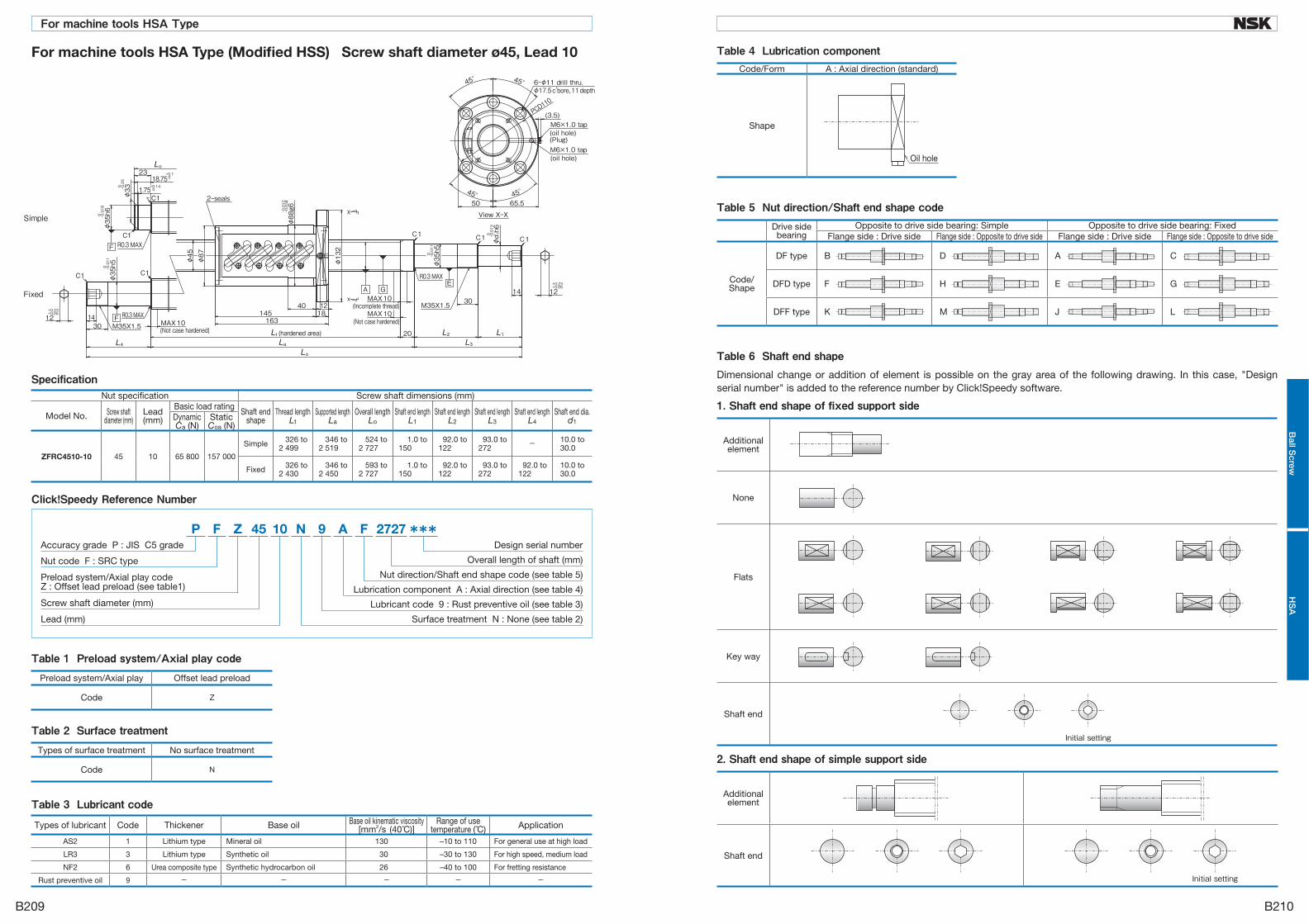
Table 1 Preload system/Axial play codePreload system/Axial play Offset lead preload
Code Z
Table 2 Surface treatmentTypes of surface treatment No surface treatment
Code N
Table 3 Lubricant codeTypes of lubricant Code Thickener Base oil Base oil kinematic viscosity
[mm2/s (40°C)]Range of use
temperature (°C) Application
AS2 1 Lithium type Mineral oil 130 –10 to 110 For general use at high load
LR3 3 Lithium type Synthetic oil 30 –30 to 130 For high speed, medium load
NF2 6 Urea composite type Synthetic hydrocarbon oil 26 –40 to 100 For fretting resistance
Rust preventive oil 9 - - - - -
Specification
***N A9 F 2727P Z 45 10F
Surface treatment N : None (see table 2)
Design serial number
Overall length of shaft (mm)
Nut direction/Shaft end shape code (see table 5)
Lubrication component A : Axial direction (see table 4)
Lubricant code 9 : Rust preventive oil (see table 3)
Lead (mm)
Nut code F : SRC type
Screw shaft diameter (mm)
Preload system/Axial play codeZ : Offset lead preload (see table1)
Accuracy grade P : JIS C5 grade
Click!Speedy Reference Number
For machine tools HSA Type (Modified HSS) Screw shaft diameter ø45, Lead 10
Nut specification Screw shaft dimensions (mm)
Model No. Screw shaft diameter (mm)
Lead(mm)
Basic load ratingShaft end
shape Thread length
Lt Supported length
La Overall length
Lo Shaft end length
L1 Shaft end length
L2 Shaft end length
L3 Shaft end length
L4 Shaft end dia.
d1DynamicCa (N)
Static Coa (N)
ZFRC4510-10 45 10 65 800 157 000
Simple 326 to2 499
346 to2 519
524 to2 727
1.0 to150
92.0 to122
93.0 to272
- 10.0 to30.0
Fixed 326 to2 430
346 to2 450
593 to2 727
1.0 to150
92.0 to122
93.0 to272
92.0 to122
10.0 to30.0
Code/Form A : Axial direction (standard)
Shape
Table 4 Lubrication component
2. Shaft end shape of simple support side
Additional element
Shaft end
Initial setting
1. Shaft end shape of fixed support side
Additional element
None
Flats
Key way
Shaft end
Initial setting
Dimensional change or addition of element is possible on the gray area of the following drawing. In this case, "Design serial number" is added to the reference number by Click!Speedy software.
Table 6 Shaft end shape
Drive side bearing
Opposite to drive side bearing: Simple Opposite to drive side bearing: FixedFlange side : Drive side Flange side : Opposite to drive side Flange side : Drive side Flange side : Opposite to drive side
Code/Shape
DF type B D A C
DFD type F H E G
DFF type K M J L
Table 5 Nut direction/Shaft end shape codeSimple
Fixed
B209
For machine tools HSA Type
B210
Ball S
crewH
SA

Table 3 Lubricant code
Table 2 Surface treatmentTypes of surface treatment No surface treatment
Code N
Table 1 Preload system/Axial play codePreload system/Axial play Offset lead preload
Code Z
Specification
***N A9 F 2742P Z 50 10F
Surface treatment N : None (see table 2)
Design serial number
Overall length of shaft (mm)
Nut direction/Shaft end shape code (see table 5)
Lubrication component A : Axial direction (see table 4)
Lubricant code 9 : Rust preventive oil (see table 3)
Lead (mm)
Nut code F : SRC type
Screw shaft diameter (mm)
Preload system/Axial play codeZ : Offset lead preload (see table1)
Accuracy grade P : JIS C5 grade
Click!Speedy Reference Number
For machine tools HSA Type (Modified HSS) Screw shaft diameter ø50, Lead 10
Nut specification Screw shaft dimensions (mm)
Model No. Screw shaft diameter (mm)
Lead(mm)
Basic load ratingShaft end
shape Thread length
Lt Supported length
La Overall length
Lo Shaft end length
L1 Shaft end length
L2 Shaft end length
L3 Shaft end length
L4 Shaft end dia.
d1DynamicCa (N)
Static Coa (N)
ZFRC5010-10 50 10 68 100 174 000
Simple 326 to2 497
346 to2 517
541 to2 742
1.0 to175
92.0 to122
93.0 to297
- 10.0 to35.0
Fixed 326 to2 430
346 to2 450
608 to2 742
1.0 to175
92.0 to122
93.0 to297
92.0 to122
10.0 to35.0
Code/Form A : Axial direction (standard)
Shape
Table 4 Lubrication component
2. Shaft end shape of simple support side
Additional element
Shaft end
Initial setting
1. Shaft end shape of fixed support side
Additional element
None
Flats
Key way
Shaft end
Initial setting
Dimensional change or addition of element is possible on the gray area of the following drawing. In this case, "Design serial number" is added to the reference number by Click!Speedy software.
Table 6 Shaft end shape
Drive side bearing
Opposite to drive side bearing: Simple Opposite to drive side bearing: FixedFlange side : Drive side Flange side : Opposite to drive side Flange side : Drive side Flange side : Opposite to drive side
Code/Shape
DF type B D A C
DFD type F H E G
DFF type K M J L
Table 5 Nut direction/Shaft end shape code
Types of lubricant Code Thickener Base oil Base oil kinematic viscosity[mm2/s (40°C)]
Range of use temperature (°C) Application
AS2 1 Lithium type Mineral oil 130 –10 to 110 For general use at high load
LR3 3 Lithium type Synthetic oil 30 –30 to 130 For high speed, medium load
NF2 6 Urea composite type Synthetic hydrocarbon oil 26 –40 to 100 For fretting resistance
Rust preventive oil 9 - - - - -
Simple
Fixed
B211 B212
Ball S
crewH
SA
For machine tools HSA Type

Table 3 Lubricant code
Table 2 Surface treatmentTypes of surface treatment No surface treatment
Code N
Table 1 Preload system/Axial play codePreload system/Axial play Offset lead preload
Code Z
Specification
***N A9 F 2742P Z 50 12F
Surface treatment N : None (see table 2)
Design serial number
Overall length of shaft (mm)
Nut direction/Shaft end shape code (see table 5)
Lubrication component A : Axial direction (see table 4)
Lubricant code 9 : Rust preventive oil (see table 3)
Lead (mm)
Nut code F : SRC type
Screw shaft diameter (mm)
Preload system/Axial play codeZ : Offset lead preload (see table1)
Accuracy grade P : JIS C5 grade
Click!Speedy Reference Number
For machine tools HSA Type (Modified HSS) Screw shaft diameter ø50, Lead 12
Nut specification Screw shaft dimensions (mm)
Model No. Screw shaft diameter (mm)
Lead(mm)
Basic load ratingShaft end
shape Thread length
Lt Supported length
La Overall length
Lo Shaft end length
L1 Shaft end length
L2 Shaft end length
L3 Shaft end length
L4 Shaft end dia.
d1DynamicCa (N)
Static Coa (N)
ZFRC5012-10 50 12 91 500 218 000
Simple 386 to2 497
406 to2 517
601 to2 742
1.0 to175
92.0 to122
93.0 to297
- 10.0 to35.0
Fixed 386 to2 430
406 to2 450
668 to2 742
1.0 to175
92.0 to122
93.0 to297
92.0 to122
10.0 to35.0
Code/Form A : Axial direction (standard)
Shape
Table 4 Lubrication component
2. Shaft end shape of simple support side
Additional element
Shaft end
Initial setting
1. Shaft end shape of fixed support side
Additional element
None
Flats
Key way
Shaft end
Initial setting
Dimensional change or addition of element is possible on the gray area of the following drawing. In this case, "Design serial number" is added to the reference number by Click!Speedy software.
Table 6 Shaft end shape
Types of lubricant Code Thickener Base oil Base oil kinematic viscosity[mm2/s (40°C)]
Range of use temperature (°C) Application
AS2 1 Lithium type Mineral oil 130 –10 to 110 For general use at high load
LR3 3 Lithium type Synthetic oil 30 –30 to 130 For high speed, medium load
NF2 6 Urea composite type Synthetic hydrocarbon oil 26 –40 to 100 For fretting resistance
Rust preventive oil 9 - - - - -
Drive side bearing
Opposite to drive side bearing: Simple Opposite to drive side bearing: FixedFlange side : Drive side Flange side : Opposite to drive side Flange side : Drive side Flange side : Opposite to drive side
Code/Shape
DF type B D A C
DFD type F H E G
DFF type K M J L
BSF type N P ----- -----
Table 5 Nut direction/Shaft end shape code
MAX
Simple
Fixed
B213 B214
For machine tools HSA TypeB
all Screw
HS
A

C-1-1 Fluoride low temperature chrome plating
The use environment of NSK linear guides and ball
screws is expending from general industrial machines,
semiconductor and flat panel display manufacturing
systems to aerospace equipment.
Among all measures to cope with environment, rust
prevention is the most challenging. Such environment
includes:
• Moisture for washing machines and other equipment
• Chemicals used in the wet processing of semiconductor
and flat panel display manufacturing equipment.
NSK has developed electrolytic rust prevention black
film treatment (black chrome plating) which is added
by fluoro resin impregnating treatment. (Hereinafter
referred as "Fluoride low temperature chrome plating".)
This surface treatment methods has proved its
superiority as the rust prevention of linear guides and
ball screws which are used in the above equipment.
● What is "Fluoride low temperature chrome plating?"
This is a type of black chrome plating which forms a
black film (1 to 2 μm in thickness) on the metal surface.
Fluoroplastic coating is added to the film to increase
corrosion resistance.
• Accuracy control is easily manageable due to
low temperature treatment and to the absence of
hydrogen embrittlement.
• Product accuracy is less affected due to the thin film
which has high corrosion resistance.
• This method is superior to other surface treatments in
durability on the rolling surface.
• Inexpensive compared with products with other
surface treatment and stainless steel products.
Do not use organic solvent because it adversely
affects antirust property of the plating.
●Chemical corrosion resistance test
C-1 Rust Prevention and Surface Treatment
Table 3 Evaluation
Available length
Rust prevention ability
Quality stability Durability Cost
Fluoride low temperature chrome plating
◎ (4m) ◎ ○ ◎ ◎
Hard chrome plating
△ (2m) ○ × △ △
Electroless nickel plating
◎ (4m) ◎ △ × △
Material equivalent to SUS440C
○ (3.5m) ○ ◎ ◎ △
◎ : Excellent ○ : Suitable in use △ : Not so good for use × : Problem in useFig. 1 Results of durability test
Peeling resistamce of surface treatment
●Surface treatment durability test ●Total evaluation
Table 2 Results of the corrosion resistance test
Test conditions Rail base material: Equivalent to SUS440C Chemical density: 1 mol/ℓ
Fluoride low temperature chrome plating
Hard chrome plating None surface treatment
○ Hydrochloric acid (immersed) ○ ▲
○ Sulfuric acid (immersed) ○ ×
○ Ammonia or sodium hydroxide ○ △
○ : Normal △ : Partial surface damage ▲ : Overall surface damage × : Corroded
HCℓ:H2O2:H2O=1:1:8
Immersed in solution for 24 hrs
Nitric acid
Immersed in solution for 24 hrs
Fluoride
Exposed to vapor for 72 hrs
Hydrochloric acid type washing solution●Humidity chamber test
Table 1 Results of the humidity test
Test sampleCharacteristic
Fluoride low temperature chrome plating(recommended)
Hard chrome plating
(reference)
Electroless nickel plating
(reference)
Equivalent to SUS440C
material
Standard steel
Top (Ground) B (Ground) B (Ground) A (Ground) C (Ground) DSide (Ground) A (Ground) A (Ground) A (Ground) C (Ground) E
Bottom (Ground) A (Ground) A (Ground) A (Ground) C (Ground) EEnd (Machined) A (Machined) C (Machined) A (Machined) C (Machined) E
Chamfer/grinding recess (Drawn) A (Drawn) D (Drawn) A (Drawn) C (Drawn) E
<Test conditions> ● Testing chamber: High
temperature, highly moist chamber
(made by DABAI ESPEC) ●Temperature: 70°C ●Relative humidity: 95% ●Testing time: 96h Time to "ramp-up" and
"ramp-down" condition of the temperature and the humidity conditions
Ramp-up: 5h Ramp-down: 2h
Film thickness 5 μm 0.5 – 7μm 10μm
Rusting A: No rust B: Not rusted, but slightly discolored C: Spotty rust D: slightly rusted E: Completely rusted
Cor
rosi
on-r
esis
tant
pro
per
ty
Rus
ting
C1 C2
Other

Table 4 Nature of Clean Grease LG2 and LGU
Name Thickener Base oilBase oil kinematic
viscosity mm2/s (40°C)
ConsistencyDropping point
°C
Clean Grease LG2 Lithium soap Synthetic hydrocarbon oil + mineral oil 32 199 201
Clean Grease LGU Diurea Synthetic hydrocarbon oil 95.8 201 260
Fig. 3 Comparison in dust emission characteristics
Fig. 5 Results of ball screw durability test
Fig. 4 Dust emission from linear guide (Linear guide: LU09)
C-2-1 NSK Clean Grease LG2 and LGU NSK Clean Grease LG2 is used in clean room for NSK linear guides, ball screws, Monocarriers, XY Modules,
Megatorque motors, XY tables, etc. with low-dust emitting specifications. For its low dust emission and high
durability, LG2 earns trust and high reputation of semiconductor equipment manufacturers.
LG2 is superior in many areas to fluorine greases which are commonly used in clean room.
Features●Remarkably low dust emission
●Long life -- More than ten times longer than fluoride greases, and equivalent to ordinary greases.
●Excellent rust prevention -- Significantly higher capacity than fluorine greases.
●Low and stable torque -- 20% or less than that of fluorine greases
●Feature 1: Remarkably low dust emission Compared with fluoride greases, dust emission by LG2 is low and stable for long period of time.
●Feature 2: Long life Life is ten times or longer than fluorine greases, and equivalent to ordinary greases. This stretches maintenance
intervals.
Fig. 2 Setting to measure dust generated by ball screw
Appearance of CleanGrease LG2
(after 3 400 km)No change
Appearance of fluorine grease(after 360 km)
abrasion dust formed owing to insufficient lubrication
C-2 Clean environment
C3 C4
Other

●Feature 3 : Excellent rust prevention capacity The rust prevention capacity is significantly higher than fluoride type greases. Handling and preparation for
operation are easy.
●Feature 4 : Stable torque Torque is 20% or lower than fluorine greases.
Type Rusting after 7 days
NSK Clean Grease LG2 No rust
Fluorine grease B Rusted
Test conditions : 19 mg is sealed in ball bearing 695 : Temp. 90°C, Humidity 60%Evaluation : Studied by microscope
Table 5 Rust prevention test on bearing
Clean Grease LG2 Fluorine grease A Ordinary grease A
Photo 1Ball screw rust prevention test
(test conditions: 96 hr at humidity 95%, temperature 70°C)
Characteristic LG2 Fluorine grease General grease
Dust generation ○ ○ –△ △ –×
Torque ○ × ○ –△
Durability ○ △ –× ○
Rust prevention ability ○ △ –× ○
○ : Suitable△ : Not very suitable× : Problem in use
● Total evaluation
Table 6 Evaluation
Table 7 Grease lubricant for linear guides and ball screws
Fig. 6 Comparison of torque characteristics
There are two types of lubricating method -- grease
and oil -- for ball screws and linear guides.
Use a lubricant agent and method most suitable
to condition requirements and purpose to optimize
functions of ball screws and linear guides.
In general, lubricants with low base oil kinematic
viscosity are used for high-speed operation, in which
thermal expansion has a large impact, and in low
temperatures.
Lubrication with high base oil kinematic viscosity is
used for oscillating operations, low speeds and high
temperatures.
The following are lubrication methods using grease
and oil.
C-3-1 Grease Lubrication Grease lubrication is widely used because it does not
require a special oil supply system or piping. Grease
lubricants made by NSK are:
• Various types of grease in bellows tubes that can be
instantly attached to a grease pump;
• NSK Grease Unit that consists of a hand grease pump
and various nozzles. They are compact and easy to use.
C-3-1.1 NSK grease lubricants Table 7 shows the marketed general grease widely
used for linear guides and ball screws for specific uses,
conditions and purposes.
C-3 Lubrication
Type Thickener Base oil Base oil kinematic viscosity
mm2/s (40°C)
Range of use temperature (°C)
Purpose
AS2 Lithium type Mineral oil 130 -10 to 110 For general use at high load
PS2 Lithium typeSynthetic oil + synthetic
hydrocarbon oil15.9 -50 to 110
For low temperature and high frequency operation
LR3 Lithium type Synthetic oil 30 -30 to 130For high speed, medium load
LG2 Lithium typeMineral oil + synthetic
hydrocarbon oil32 -20 to 70 For clean environment
LGU DiureaSynthetic
hydrocarbon oil95.8 -30 to 120 For clean environment
NF2Urea composite
typeSynthetic
hydrocarbon oil26 -40 to 100 For fretting resistance
No rust No rustRusting
C5 C6
Other

(1) NSK Grease AS2●Features It is an environmentally friendly and widely used grease
for high load application. It is mineral oil based grease
containing lithium thickener and several additives. It is
superb in load resistance as well as stability in oxidization.
It not only maintains good lubrication over a long period
of time, but also demonstrates superb capability in
retaining water. Even containing a large amount of water,
it does not lose grease when it is softened.
●Application It is a standard grease for general NSK linear guides
and ball screws. It is prevalently used in many applications
because of its high base oil viscosity, high load resistance,
and stability in oxidization.
(4) NSK Grease LG2●Features This grease was developed by NSK to be exclusively
used for linear guides and ball screws in clean room.
Compared to the fluorine grease which are commonly
used in clean room, LG2 has several advantages such
as:
• Higher in lubrication function
• Longer lubrication life
• More stable torque (resistant to wear)
• Higher rust prevention.
In dust generation, LG2 is more than equal to fluorine
grease in keeping dust volume low. Since the base oil is
not a special oil but a mineral oil, LG2 can be handled
in the same manner as general greases.
●Application LG2 is a lubrication grease for rolling element products
such as linear guides and ball screws for semiconductor
and flat panel display (FPD) processing equipment
which require a highly clean environment. Because
LG2 is exclusively for a clean environment at normal
temperatures, however, it cannot be used in a vacuum
environment.
Refer to "Clean environment" in page C3 for detailed
data on superb characteristics of NSK Grease LG2.
(5) NSK Grease LGU●Features This is a proprietary urea base grease of NSK featuring
low dust emission exclusively for ball screws and linear
guides which are used in clean rooms.
In comparison with fluorine base grease, which has
been used commonly in clean rooms, LGU has better
lubricating property, longer duration of lubricant, better
torque variation, much better anti-rust property, and
equivalent or better dust emission. In addition, this
grease can be handled in the same way as the other
common grease because high-grade synthetic oil is
used as the base oil.
LGU grease contains much less metallic elements
compared to LG2 grease. It can be used in high
temperature environment.
●Application This is exclusive lubrication grease for ball screws
and linear guides that are installed in equipment that
requires cleanliness, as same as LG2 grease, and it can
be used in high temperature range of – 30 to 120°C.
This cannot be used in vacuum.
Thickener Lithium soap base
Base oil Mineral oil
Consistency 275
Dropping point 181°C
Volume of evaporation 0.24% (99°C, 22 hr)
Copper plate corrosion test
Satisfactory (Method B, 100°C, 24 hr)
Oil separation 2.8% (100°C, 24 hr)
Base oil kinematic viscosity 130 mm2/s (40°C)
●Nature
Thickener Lithium soap base
Base oil Mineral oil + Synthetic
hydrocarbon oil
Consistency 199
Dropping point 201°C
Volume of evaporation 1.40% (99°C, 22 hr)
Copper plate corrosion
test
Satisfactory
(Method B, 100°C, 24hr)
Oil separation 0.8% (100°C, 24 hr)
Base oil kinematic viscosity 32mm2/s (40°C)
●Nature
(2) NSK Grease LR3● Features It contains a special synthetic oil for high temperature
and stability, and a carefully selected anti-oxidation
agent. This grease dramatically increases lubrication life
under high temperature conditions. It is used for high
speed, medium load. Lubrication life exceeded 2 000
hours in the endurance test at 150°C. Its rust prevention
capacity in severe conditions such as water and moist
environments is further strengthened.
●Application It is a standard grease for ball screws PSS type (shaft
dia. 15 mm or over), FSS type and FA type (except
shaft dia. 10 mm with lead of 4mm and shaft dia. 12
mm with lead of 5 mm). It is ideal for operation with
medium load, at high speed such as positioning in high
tact material handling equipment.
Thickener Lithium soap base
Base oil Synthetic oil
Consistency 228
Dropping point 208°C
Volume of evaporation 0.58% (99°C, 22 hr)
Copper plate corrosion test
Satisfactory (Method B, 100°C, 24 hr)
Oil separation 1.9% (100°C, 24 hr)
Base oil kinematic viscosity 30mm2/s (40°C)
●Nature
Thickener Diurea
Base oil Synthetic hydrocarbon oil
Consistency 201
Dropping point 260°C
Volume of evaporation 0.09% (99°C, 22 hr)
Copper plate corrosion test
Satisfactory (Method B, 100°°C, 24 hr)
Oil separation 0.6% (100°C, 24 hr)
Base oil kinematic viscosity 95.8mm2/s (40°C)
●Nature
(3) NSK Grease PS2●Features The major base oil component is synthetic oil with
mineral oil. It is an excellent lubrication especially for low
temperature operation. It is for high speed and light load.
●Application It is a standard grease for NSK miniature linear
guides and ball screws. It is especially superb for low
temperature operation, but also functions well in normal
temperatures, making it ideal for small equipment with
light load.
Thickener Lithium soap base
Base oil Synthetic oil + Synthetic hydrocarbon oil
Consistency 275
Dropping point 190°C
Volume of evaporation 0.60% (99°C, 22 hr)
Copper plate corrosion test
Satisfactory (Method B, 100°C, 24 hr)
Oil separation 3.6% (100°C, 24 hr)
Base oil kinematic viscosity 15.9mm2/s (40°C)
●Nature
C7 C8
Other

(6) NSK Grease NF2●Features It uses high-grade synthetic oil as the base oil and
urea base organic compound as the thickener. It has
remarkable anti-fretting corrosion property. It can be
used in wide temperature range, from low to high, and
has superior lubrication life.
●Application This grease is suitable for ball screws and linear guides
of which application include oscillating operations.
Allowable temperature range is –40 to 100°C.
C-3-1.3 How to replenish grease and volume of grease to be replenished
Use grease f i t t ing i f exclusive grease supply
component is not used. Supply required amount
through grease fitting by a grease pump.
Wipe off old grease and accumulated dust before
supplying new grease. If grease fitting is not used or
there is no oil filler due to the size limitation, apply
grease directly to the rail or to the ball groove of the
screw shaft. Remove the seal if possible, move a
ball slide or ball nut a few strokes so that the grease
permeates into the ball slide, nut and inside the slider.
Once grease is replenished, another supply is not
required for a long time. But under some operational
conditions, it is necessary to periodically replenish
grease. The following are replenishing methods.
*When replenishing using a grease pump:
Use a grease pump and fill the inside of ball slide and
ball nut with grease. Supply grease until it comes out
from the ball slide or ball nut slider area. Move ball slide
or ball nut slider by hand while filling them with grease,
so the grease permeates all areas.
Do not operate the machine immediately after
replenishing. Always try the system a few times
to spread the grease throughout the system and
to remove excess grease. Tr ia l operat ions are
necessary because the resistance to sliding force
and screw torque greatly increases immediately
after replenishment (full-pack state) and may cause
problems. The agitating resistance of grease is
accountable for this phenomenon. Wipe off excess
grease that accumulates at end of rail and screw shaft
after trial runs so the grease does not move to other
areas.
*When there is an exclusive grease supply system
and the volume from the spout can be controlled, the
criterion is:
• All at once, replenish the amount that fills about 50%
of the internal space of the ball slide or the internal
space of the ball nut. This method eliminates waste
of grease and is efficient.
Tables 8 and 9 show internal spaces of ball slide and
ball nut for reference.
C-3-1.2 Before use of NSK Precision Products Wipe off the rust preventive oil before use for the products that the oil is applied.
If grease is not applied, apply grease, and move a ball slide or ball nut a few strokes so the grease permeates into
the ball slide and inside the nut. (Move the ball slide or the ball nut 5 to 10 times with full stroke.)
Then wipe off the excess grease.
Thickener Diurea
Base oil Synthetic hydrocarbon oil
Consistency 288
Dropping point 260°C
Volume of evaporation 0.22% (99°C, 22 hr)
Copper plate corrosion
test
Satisfactory
(Method B, 100°C, 24 hr)
Oil separation 0.5% (100°C, 24 hr)
Base oil kinematic viscosity 26mm2/s (40°C)
●Nature
• Wash the linear guides and ball screws to remove oil prior to applying Clean Grease LG2 or LGU, so the
grease functions are fully utilized.
• Clean grease is exclusively used for clean environments at normal temperatures.
Note) Refer to NSK Grease Unit Catalog (CAT. No.E3317) for details of NSK Grease.
C9 C10
Other

Table 8 Inside space of the slide of linear guide Table 9 Inside space of ball nutReturn tube type (single nut)NH Series
SeriesModel No.
NHHigh-load type Super-high-load type
15 3 420 6 825 9 1330 13 2035 22 3045 47 5955 80 10065 139 186
Unit: cm3
PU Series
SeriesModel No.
PUStandard type High-load type
09 0.2 0.312 0.3 0.415 0.8 1.1
Unit: cm3
NS Series
SeriesModel No.
NSMedium-load type High-load type
15 2 320 3 425 5 830 8 1235 12 19
Unit: cm3
RA Series
SeriesModel No.
RAHigh-load type Super-high-load type
25 3 3.530 5 635 6 845 10 13
Unit: cm3
PE Series
SeriesModel No.
PEStandard type High-load type
09 0.4 0.512 0.5 0.715 1.2 1.6
Unit: cm3
LW Series Unit: cm3
SeriesModel No.
LW
17 321 327 735 24
Table 10 Intervals of checks and replenishments for grease lubrication
Intervals of checks Items to check Intervals of replenishments
3-6 months Dirt, foreign matters such as cutting chips
Usually once per year. Every 3 000 km for material handling system that travels more than 3 000 km per year. Replenish if checking results warrant it necessary.
C-3-1.4 Intervals of checks and replenishments Although the grease is of high quality, it gradually
deteriorates and its lubrication function diminishes.
Also, the grease in the ball slide and ball nut is
gradually removed by stroke movement. In some
environments, the grease becomes dirty, and foreign
objects may enter. Grease should be replenished
depending on frequency of use. The following is a
guide of grease replenishment intervals for linear guides
and ball screws.
Notes: 1) As a general rule, do not mix greases of different brands. 2) Grease viscosity varies by temperature. Viscosity is particular high in winter due to low temperatures. Pay attention to
increases in linear guide and ball screw in such conditions. 3) When the ambient temperature is low, or in Winter, if it is difficult to pump out the grease from the container, wait until the grease is softened. 4) In locations where coolant is dispersed or scattered, emulsification of lubricants and rinsing with water may significantly deteriorate the
integrity of the lubricant and efficiency of the grease. Protect the grease unit from coolant by shielding it with a cover, etc.
Nut model Inside space Nut model Inside space Nut model Inside space Nut model Inside space1004-2.5 0.8 1616-1.5 2.1 2506-5 7 2806-10 9.51205-2.5 1.2 2004-5 2.7 2510-3 9.5 3205-5 71210-2.5 1.4 2005-5 4.3 2520-2.5 12 3206-5 9.51405-2.5 2.2 2010-2.5 4.7 2525-1.5 7.5 3210-5 221408-2.5 2.1 2020-1.5 4.2 2805-5 6 3225-2.5 171510-2.5 2.3 2504-5 3.2 2805-10 9 3232-1.5 151605-2.5 2.6 2505-5 5 2806-5 6
Unit: cm3
End cap type
Nut model Inside space1520-1.5 1.91632-1 2.02040-1 2.82550-1 4.2
Unit: cm3
Miniature deflector (bridge) typeUnit: cm3
Nut model Inside space0401-2 0.10601-3 0.20801-3 0.30801.5-3 0.20802-3 0.31002-3 0.41002.5-3 0.61202-3 0.51202.5-3 0.81602-4 1.61602.5-4 1.6
End deflector type Unit: cm3
Nut model Inside space Nut model Inside space Nut model Inside space0608-2E 0.2 1205-3E 1.0 2005-3E 3.40608-4E 0.3 1210-3E 1.0 2010-3E 3.20612-2E 0.2 1220-2E 1.2 2020-2E 3.20612-4E 0.3 1230-2E 1.5 2030-2E 4.60810-2E 0.4 1505-3E 2.0 2040-2E 5.30810-4E 0.5 1510-3E 2.0 2060-2E 7.00815-2E 0.4 1520-2E 2.8 2505-3E 4.40815-4E 0.6 1530-2E 3.4 2510-4E 4.71005-3E 0.8 2520-2E 3.91010-2E 0.7 2525-2E 4.3
2530-2E 5.52550-2E 7.7
Nut model Inside space Nut model Inside space3205-10 10 4510-10 583210-10 43 5010-10 644010-10 52 5012-10 994012-10 67
SRC type Unit: cm3
Middle deflector typeUnit: cm3
Nut model Inside space4016-4E 404020-4E 47
C11 C12
Other

Name (Tube color) Reference numberNSK Grease Unit
NSK Grease NSK Grease AS2 (Brown) NSK GRS AS2
(80 g in a bellows tube)
NSK Grease PS2 (Orange) NSK GRS PS2
NSK Grease LR3 (Green) NSK GRS LR3
NSK Grease LG2 (Blue) NSK GRS LG2
NSK Grease LGU (Yellow) NSK GRS LGU
NSK Grease NF2 (Gray) NSK GRS NF2
NSK Hand Grease Pump Unit
NSK Hand Grease Pump NSK HGP
(Straight nozzle NSK HGP NZ1 -- One nozzle is provided with hand pump.)
Grease nozzle (used with hand grease pump)
NSK straight nozzle NSK HGP NZ1
NSK chuck nozzle NSK HGP NZ2
NSK drive-in fitting nozzle NSK HGP NZ3
NSK point nozzle NSK HGP NZ4
NSK flexible nozzle NSK HGP NZ5
NSK flexible extension pipe NSK HGP NZ6
NSK straight extension pipe NSK HGP NZ7
C-3-1.5 NSK Grease Unit Supply grease to NSK linear guides and ball screws by manual type hand grease pump. Install grease in bellows
tube to the pump. Several types of grease (80 g) are available.
(2) NSK Greases (80 g in bellows tube) Refer to pages C7, C8 and C9 for their natures and details.
(3) NSK Manual Grease Pump Unit
①NSK Hand Grease Pump (Reference number: NSK HGP)
●Features ・ Light-weight ・・・・・・・・・・・ Can be operated by one hand,
yet there is no worry to make a
mistake.
・ Inserting by high pressure ・・・ Insert at 15 Mpa.
・ No leaking ・・・・・・・・・・・・・ Does not leak when held
upside down.
・ Easy to change grease ・・・ Simply attach grease in
bellows tube.
・ Remaining grease ・・・・・ Can be confirmed through
slit on tube.
・ Several nozzles ・・・・・・・・ Five types of nozzles to
choose from.
●Specifications ・ Discharge pressure ・・・・15 Mpa
・ Spout volume ・・・・・・・・・・0.35 cc/shot
・ Mass of main body ・・・・Without nozzle 240 g
Provided nozzle 90 g
・ Grease tube outer diameter φ38.1
・ Accessory ・・・・・・・・・・・・・・ Several nozzles for a unique
application can be attached
(1) Composition of NSK Grease Unit Components and grease types are shown below.
Grease in bellows tubeFig. 7 Bellows tube
Fig. 8 NSK Hand Grease Pump with NSK straight nozzle
* Air is contained in the unopened bellows tube. Try the system tens of times when to use the hand grease pump. The tube will be use after deflated from the tube.
C13 C14
Other

Name Designation code Use Dimensions
NSKstraightnozzle
NSK HGP NZ1Can be used with grease fitting A, B, and C under JIS B1575 standard.
NSKchucknozzle
NSK HGP NZ2
Same as above.However, there is no need to press the hand pump because the grease fitting and the nozzle come to contact due to the chucking mechanism at the tip.
NSKdrive-in fittingnozzle
NSK HGP NZ3Dedicated for the -φ3 drive-in grease fitting.
NSKpoint
nozzleNSK HGP NZ4
Used for linear guides and ball screws which do not have grease fitting. Supplies grease directly to the ball grooves, or through the opening of ball slide or ball slide to inside.
NSKflexiblenozzle
NSK HGP NZ5The tip of the flexible nozzle is chuck nozzle. The straight nozzle is not available for use.
NSKflexible
extension pipe
NSK HGP NZ6Flexible extension pipe connects the grease pump and the nozzle
NSKstraight
extension pipe
NSK HGP NZ7Straight extension pipe connects the grease pump and the nozzle.
Series Model No.Tap hole for
grease fitting
Standard grease fitting
Straight nozzleNZ1
ChucknozzleNZ2
Drive-in fittingnozzleNZ3
Point nozzleNZ4
FlexiblenozzleNZ5
NH
NH15 φ3 Drive-in type ○
NH20、25、30、35* M6×0.75 B type ○ ○ ○
NH45、55、65 Rc1/8 B type ○ ○ ○
NSNS15 φ3 Drive-in type ○
NS20、25、30、35* M6×0.75 B type ○ ○ ○
LWLW17 φ3 Drive-in type ○
LW21、27、35* M6×0.75 B type ○ ○ ○
PUPU09、12 - - ○
PU15 φ3 Drive-in type ○
PEPE09、12 - - ○
PE15 φ3 Drive-in type ○
RARA25、30、35* M6×0.75 B type ○ ○ ○
RA45 Rc1/8 B type ○ ○ ○
Table 11 Nozzles that can be attached to NSK Hand Grease Pump
Table 12 Grease fittings used for NSK linear guide②Nozzles
Fig. 9 Grease fittings
*) If using a chuck nozzle, avoid interference with table and rail.Note: 1) For PU and PE Series, apply grease directly to ball groove, etc. using point nozzle. 2) A long threaded grease fitting is required for NSK linear guides because of dust-proof parts.
C15 C16
Other

C-3-2 Oil Lubrication Required amount of new oil is regularly supplied by:
• Manual or automatic intermittent supply system;
• Oil mist lubricating system via piping.
Equipment for oil lubrication is more costly than grease lubrication. However, oil mist lubricating system supplies
air as well as oil, raising the inner pressure of the ball slide. This prevents foreign matters from entering, and the air
cools the system. Use an oil of high atomizing rate such as ISO VG 32 to 68 for the oil mist lubrication system.
ISO VG 68 to 220 are recommended for common intermittent replenishment system. Approximate volume of oil Q
for a ball slide of linear guide per hour can be obtained by the following formula.
In case of ball type linear guides Q ≥ n / 150 (cm3/hr) In case of RA Series Q ≥ n / 100 (cm3/hr) n : Linear guide code e.g. When NH45 is used, n = 45 Therefore, Q = 45 / 150= 0.3 cm3/hr Similarly, approximate oil supply volume Q to ball screw can be obtained by the following formula.
Q = d / 15 (cm3/hr) d : Nominal shaft diameter of the ball screw e.g. When the shaft diameter is 50, d = 50 Therefore, Q = 50 / 15= 3.3 cm3/hr For oil lubrication by gravity drip, the oil supply position and installation position of the ball slide or ball nut are
crucial. In case of linear guide, unless it is installed to a horizontal position, the oil flows only on the down side, and
does not spread to all raceway surface. This may cause insufficient lubrication. For ball screw lubrication as well,
oil does not spread if the oil orifice is installed at the bottom, causing insufficient lubrication. Please consult NSK to
correct such situations prior to use. NSK has internal design which allows oil lubricant to flow throughout the system.
Table 14 shows the criterion of intervals of oil checks and replenishments.
Table 14 Intervals of checks and replenishments
Method Intervals of checks Items to check Replenishment or intervals of changes
Automatic intermittent supply Weekly Volume of oil, dirt, etc. Replenish at each check. Suitable volume for tank capacity.
Oil bath Daily before operation Oil surface Make a suitable criterion based on consumption
Notes: 1) As with grease lubrication, do not mix oil lubricant with different types. 2) Some components of the linear guide and ball screw are made of plastic. Avoid using an oil that adversely affects synthetic resin. 3) When using oil mist lubricating system, please confirm an oil supply amount at the each outlet part.
For details of country-specific RoHS, contact NSK.
C-4 RoHS Compliant
C17 C18
Other
Table 13 Applicable grease nozzle for ball screws
SeriesTap hole forgrease fitting Model No.
Tap hole for grease
fitting
Standard grease fitting
Straight nozzleNZ1
ChucknozzleNZ2
Drive-in fittingnozzleNZ3
Point nozzleNZ4
FlexiblenozzleNZ5
Finishedshaft end
Compact FA
High-accuracy,clean USS
M5×0.8
A type ○ ○ ○ ○
General PSS A type ○*1 ○*1 ○ ○*1
Transfer equipment FSS A type ○*1 ○*1 ○ ○*1
Miniature, fine lead MA
Shaft dia. 12 or less ー ー ○
Shaft dia. 16 or over M6×1 ー ○
Small equipment FA M6×1 ー ○*2 ○*2 ○ ○*2
Machine tools SA
Shaft dia. 36 or less M6×1 ー ○ ○ ○ ○
Shaft dia. 40 or over Rc1/8 ー ○ ○ ○ ○
Blankshaft end Machine tools HSS M6×1 ー ○ ○ ○ ○
*1 Unavailable for shaft dia. 25 mm *2 If using A type grease fitting, may not install the nozzle. Notes: 1) Normally, grease fitting is not provided to NSK ball screw except Compact FA Series. Ball nut has a tap hole to install
a grease fitting. The user should install a grease fitting if necessary. 2) MA type has no tap hole, apply grease directly to the screw shaft and ball grooves using point nozzle.