Embed Size (px)
Citation preview

IJCTA Vol.8, No.1, Jan-June 2015, Pp.237-252
© International Sciences Press, India
A Novel Two Diode Model of Pv Module for
MPPT with Neural Compensator
Mr. A. Sriharibabu1, Mr. J.Jithendranath2, Mr. Ch. Uma Maheswara Rao3, Dr. G.Durgasukumar4 1,2,3
Assistant Professor, 4Associate Professor and HOD, Dept of EEE, VFSTR University, Vadlamudi.
ABSTRACT
This paper deals with the improved model(Two Diode Model) of solar photovoltaic (SPV) module and
back propagation neural network based maximum power point tracking (MPPT) for boost converter in a
standalone photovoltaic system under variable temperature and insolation conditions. ie. The proposed
model is robust to environment changes and load variations. Unlike Conventional solar-array
mathematical model, Neural network modeling does not require any physical definitions for a
photovoltaic array, hence they have a potential to provide a superior method of deriving non-linear
models than the already established conventional techniques. In this paper back-propagation
neural network trained model is employed to simulate and predict the maximum power point of a Photo
Voltaic array using a random set of data collected from a real photovoltaic array. In order to
validate the developed simulation model, simulated results from the proposed model under standard
conditions are compared with specifications of commercially available USL Solar PV module (USP-
75) and BP-350U PV Modules. There is a very good agreement between the results. And the functioning
of the proposed model and predicted maximum power point of the photo-voltaic array are evaluated by
simulation using Matlab/simulink GUI environment.
Keywords: PV module, MPPT, Back Propagation Algorithm.
1. INTRODUCTION
Generation of electricity from sun light is a direct means of obtaining power for low and medium level energy generation is one of the methods of harnessing solar energy. This method comprises of cells arranged in a specific fashion, commercially called as PV system. A PV system is made of a group of arrays connected in series and parallel combinations depending on the required voltage and current levels as specified by the loads. PV systems along with the electronic converters are predominant to handle domestic/industrial loads or to interconnect it to the grid [1]. For effective utilization of tapped solar energy, it requires the knowledge of both PV system design/modeling and electronic converter design, the former aspect is considered in this paper.
The modeling of PV system attached to an electronic converter plays a vital role in order to characterize the practical PV system. The performance of PV depends on solar insolation, ambient temperature, and load impedance. As PV devices have non linear V-I characteristics with various parameters that are influenced by the external causes, it requires effective methods to account and quantify them in modeling the PV

238
devices. Also a PV system is a power source having nonlinear internal resistances that varies corresponding to the variation in light intensity falling on it. Different models have been proposed in the literature accounting various causes in [2 - 5]. In this paper a precise method of modeling the PV system is proposed that can handle all factors which cause to affect its performance such as its non linear internal resistances, recombination loss in PV cell, etc., that provides an accurate model for simulation [6].
The amount of power that can be trapped from the PV system depends upon various factors listed above and in addition to that it depends on the Tracking phenomenon implemented for power trapping. To extract maximum power from the panel, various approaches for tracking maximum power point (MPP) have been addressed in literature. The general requirements for maximum power point tracker (MPPT) are simple, low cost, quick tracking under dynamic atmospheric conditions and small output power fluctuations. Hence more efficient method for better tracking becomes crucially important. So far many tracking control strategies have been proposed such as perturb and observe, incremental conductance, parasitic capacitance, constant voltage and fuzzy logic strategies which have some disadvantages such as costly, difficulty, complexity and non-stability [7 – 10]. In the present context, Artificial Neural Network (ANN) technology has attracted widespread interest in electrical engineering because of its adaptability, accuracy and as a realistic method of solving inters disciplinary problems [11]. This paper presents idea of adopting neural network technology which provides efficient method for better tracking of MPP of PV system under dynamic atmospheric conditions and small output power fluctuations.
2. MODELING OF PV DEVICE
The mathematical modeling of PV device is necessary to analyze the electronic converters that are used in building a entire PV generation module. As the manufactures provide set of data at different operating conditions that can be used to develop a mathematical model for the PV device. The process of mathematical modeling of PV device provides the initial step in obtaining the final model of PV generation system.
2.1. Single diode model
The PV cell modeled based on single diode will have current source in parallel with a reverse biased diode and with series/parallel internal resistances, as shown in Figure.1 [12]. The output current (I) can be written as
𝐼 = 𝐼𝑃𝑉 − 𝐼𝑜 𝑒𝑥𝑝 𝑉 + 𝐼𝑅𝑠𝑎𝑉𝑇
− 1 − 𝑉 + 𝐼𝑅𝑠𝑅𝑝
… (1)
239
Figure 1. Single Diode Model
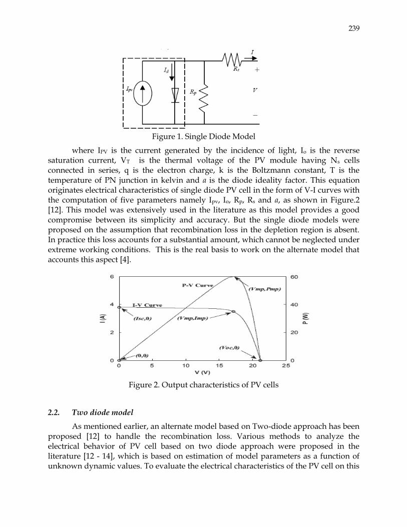
where IPV is the current generated by the incidence of light, Io is the reverse saturation current, VT is the thermal voltage of the PV module having Ns cells connected in series, q is the electron charge, k is the Boltzmann constant, T is the temperature of PN junction in kelvin and a is the diode ideality factor. This equation originates electrical characteristics of single diode PV cell in the form of V-I curves with the computation of five parameters namely Ipv, Io, Rp, Rs and a, as shown in Figure.2 [12]. This model was extensively used in the literature as this model provides a good compromise between its simplicity and accuracy. But the single diode models were proposed on the assumption that recombination loss in the depletion region is absent. In practice this loss accounts for a substantial amount, which cannot be neglected under extreme working conditions. This is the real basis to work on the alternate model that accounts this aspect [4].
Figure 2. Output characteristics of PV cells
2.2. Two diode model
As mentioned earlier, an alternate model based on Two-diode approach has been proposed [12] to handle the recombination loss. Various methods to analyze the electrical behavior of PV cell based on two diode approach were proposed in the literature [12 - 14], which is based on estimation of model parameters as a function of unknown dynamic values. To evaluate the electrical characteristics of the PV cell on this

240
approach is a tedious task due to lack of complete information about semi-conductor parameters that are not available in Commercial data sheets of PV cells.
A generalized approach has been proposed to characterize the complete PV cell behavior based on the information readily available on data sheet. The main emphasis on this approach is the simplification of current equation with minimum number of unknown parameters that can be evaluated by both algebraic and iterative manner. The equivalent circuit for the two-diode model proposed in [12] is shown in Figure.3. The simplified current equation for the model is:
Figure 3. Two Diode Model
𝐼 = 𝐼𝑃𝑉 − 𝐼𝑜1 𝑒𝑥𝑝 𝑉 + 𝐼𝑅𝑠𝑎1𝑉𝑇1
− 1 − 𝐼𝑜2 𝑒𝑥𝑝 𝑉 + 𝐼𝑅𝑠𝑎2𝑉𝑇2
− 1 − 𝑉 + 𝐼𝑅𝑠𝑅𝑝
… (2)
Where Io1 and Io2 are the reverse saturation currents of diodes D1 and D2 respectively, VT1 and VT2 are the thermal voltages of respective diodes, a1 and a2 represents ideality constants of respective diodes. The significance of additional diode is to compensate for recombination loss in the depletion region of PV cell.
The simplicity of the two diode model in [12] as compared to the proposed two diode models in the literature [13, 14] can be acceptable with the approach followed in evaluating the model parameters that are discussed in subsequent sections.
2.3. Determination of parameters in two diode model
The two diode model considered in present aspect requires four parameters, compared to six or more in the previously developed two-diode models. The simplified current equation of PV cell for two diode model as described in equation (2) has seven parameters namely IPV, Io1,Io2,Rp,Rs, a1 and a2 to be computed, in which the four parameters Io1,Io2,Rp and Rs are evaluated by iterative methods [12].
2.3.1. Simplified current equations
a. Expression for PV current,
The expression for PV current as a function of irradiance and temperature can be written as,

241
𝐼𝑃𝑉 = 𝐼𝑃𝑉_𝑆𝑇𝐶 + 𝐾𝐼∆𝑇 𝐺
𝐺𝑆𝑇𝐶… (3)
where IPV_STC is the current generated due to light at STC, T=T-TSTC, G is the surface irradiance of cell and GSTC is the irradiance at STC and KI is the short circuit current coefficient available in manufacture's datasheet.
b. Simplified expression for saturation current equation,
The expression for saturation current for single diode model considering the temperature variation can be written as,
𝐼𝑂 = 𝐼𝑆𝐶_𝑆𝑇𝐶 + 𝐾𝐼∆𝑇
𝑒𝑥𝑝 𝑉𝑜𝑐 ,𝑆𝑇𝐶 + 𝐾𝑉∆𝑇 / 𝑎𝑉𝑇 − 1… (4)
where KV is the open circuit voltage coefficient available in manufacture's datasheet.
Now for two diode model, to have simplified expression for saturation currents in two diodes their magnitudes can be made equal to have same computational effort as with simple single diode model. The expression for reverse saturation currents Io1 and Io2 which are set to be equal can be written as,
𝐼𝑂1 = 𝐼𝑂2 = 𝐼𝑂 = 𝐼𝑆𝐶_𝑆𝑇𝐶 + 𝐾𝐼∆𝑇
𝑒𝑥𝑝 𝑉𝑜𝑐 ,𝑆𝑇𝐶 + 𝐾𝑉∆𝑇 / 𝑎1 + 𝑎2 /𝑝 𝑉𝑇 − 1… (5)
The diode ideality factors a1 and a2 represent diffusion and recombination current components respectively. These ideality factors can be generalized with the following relations, i.e., ( a1 + a2)/p = 1, a1 =1 and p≥2.2. Now equation (2) can be simplified in terms of p as
𝐼 = 𝐼𝑃𝑉 − 𝐼𝑜 𝑒𝑥𝑝 𝑉 + 𝐼𝑅𝑠𝑉𝑇
+ 𝑒𝑥𝑝 𝑉 + 𝐼𝑅𝑠 𝑝 − 1 𝑉𝑇
+ 2 − 𝑉 + 𝐼𝑅𝑠𝑅𝑝
… (6)
2.3.2. Evaluating Rs and Rp values
The simplified current equation of PV cell as stated in equation (6) above, when evaluated for practical condition still remains with unknowns of Rs and Rp. Many articles reported in the literature were based on independent evaluation of Rs and Rp values, which results much deviation in its electrical performance when compared to practical values. Hence a simultaneous evaluation of Rs and Rp with iterative approach, was taken to bring the two-diode model in close with the practical PV model.

242
The method of evaluating Rs and Rp is shown in the pseudo code, however initialization of this resistances can be made as follows:
𝑅𝑝
=𝑉𝑚𝑝 + 𝐼𝑚𝑝𝑅𝑠
𝐼𝑃𝑉 − 𝐼𝑂 𝑒𝑥𝑝 𝑉𝑚𝑝 + 𝐼𝑚𝑝𝑅𝑠 /𝑉𝑇 + 𝑒𝑥𝑝 𝑉𝑚𝑝 + 𝐼𝑚𝑝𝑅𝑠 / 𝑝 − 1 𝑉𝑇 + 2 − 𝑝𝑚𝑎𝑥 ,𝐸/𝑉𝑚𝑝 … (7)
𝑅𝑠𝑜 = 0; 𝑅𝑝𝑜 =𝑉𝑚𝑝
𝐼𝑠𝑐𝑛 −𝑉𝑚𝑝−
𝑉𝑜𝑐𝑛 −𝑉𝑚𝑝
𝐼𝑚𝑝… (8)
Solving Algorithm: In what follows, the algorithm in pseudo code is given:
Step1: Inputs T,G,Kv,a1,a2,p, Pmax,exp, Rs=0,Rp=Rp(min)(Eqn (8))
Step2: Evaluate Io (=Io1 =Io2), Eqn (5),Pmax(from Eqn (6))
Step3: Compute 𝜀(=Pmax-Pmax,exp)
Step4: If 𝜀 > tolerance, go to Step5, If not end
Step5: Increment Rs, Solve Eqn (7), & go to Step2.
The two diode model, stated above is well accepted because of its coincidence with various practical PV models under dynamic irradiance and temperatures. In particular this model exhibits an excellent correlation at lower irradiance levels that makes this model a suitable design tool for PV system designers [12].
3. PRACTICAL VALIDATION OF TWO DIODE MODEL
The two diode model discussed above, was validated by implementing it in MATLAB R2009b/SIMULINK GUI (Graphical User Interface) Environment as shown in Figure.4, and by conducting suitable tests on the experimental setup shown in Figure.7.
Figure 4. GUI block of the Complete PV cell Simulink diagram

243
USP 75 M5C01 Solar Panel PV module is chosen for the validation of the developed model in MATLAB. The USP-75 module provides 75 watt of maximum power, and has 36 series connected polycrystalline silicon cells and the simulated results are validated against the practical results obtained from the experimental setup at standard test conditions of sun radiation: 1000 watt/sq.m and 25 deg C temperature as tabulated in Table 1. The MATLAB model I-V and P-V characteristics for different insolations and at 25 deg C temperature are shown in Figure.5 and Figure.6
TABLE - I Validation between practical and simulated models
Standard parameters Pmax Vmax Imax Voc Isc
USP-75 75.00W 17.1V 4.39A 21.5V 4.90A
MATLAB Model 75.55W 17.16V 4.40A 21.5V 4.90A
Figure 5. I-V characteristics Figure 6. P-V characteristics
Figure 7. Experimental setup
4. PROPOSED MPPT TECHNIQUE
To extract maximum power from the panel, various approaches for tracking maximum power point (MPP) but it lacks with practical implementation, due to its

244
mismatch with the general requirements for maximum power point tracker (MPPT) such as simplicity, low cost, quick tracking under dynamic atmospheric conditions and small output power fluctuations [7 -10].
Figure 7. Maximum Power Line with varying weather condition
The typical variations of output voltage versus current for various temperatures of USP 75 M5C01 Solar Panel PV module are shown in Figure.7 [15], as the output voltage rises, the PV produces significant less current. The I-V curve will change depending on the temperature and illumination. The operating voltage or current needs to be carefully controlled so that the maximum power from the array can be obtained.
Also, in order to minimize the long-term system losses, it is required that converter output current has very small ripple and conversion efficiency is very high even at part load [16]. Therefore the installation of a boost type converter is advised and the same is adopted in this paper. The block diagram of the proposed MPPT scheme is shown in Figure. 8.
Figure 8. Block diagram of the proposed MPPT scheme

245
The conventional solar-array mathematical model will give satisfactory result, provided with the physical parameters relating to solar-cell material, weather condition, solar trajectory, illumination factor and temperature. At times due to lack of this information, the derived mathematical model may be inaccurate [2-5]. Neural network modeling does not require any physical definitions for a photovoltaic array, hence they have a potential to provide a superior method of deriving non-linear models than the already established conventional techniques. The Solar array was modeled using artificial intelligence technique, ANN namely Back Propagation [17].
4.1 Back propagation neural network
The general requirements for maximum power point tracker (MPPT) are simple and low cost, quick tracking under condition change, and small output power fluctuation. A more efficient method to solve this problem becomes crucially important. Neural network technology has attracted widespread interest in electrical engineering even many tracking control strategies have been proposed such as perturb and observe, incremental conductance, parasitic capacitance, constant voltage and fuzzy logic strategies have some disadvantages such as costly, difficulty, complexity and non-stability [7 - 10].
As Artificial Intelligence Technique evolved for modeling of non-linear systems, a model based on Fuzzy Logic was suggested for modeling of MPPT. However, the limitation of this technique was that the maximum power point was based on the short circuit current measured on the load side of the system and this current cannot be measured continuously; hence this technique lacks the ability of continuous tracking [10].
Back-propagation is a multilayer feed forward network and it was created by generalizing the Widrow-Hoff learning rule to multiple-layer networks and nonlinear differentiable transfer functions [17]. Input vectors and the corresponding target vectors are used to train a network until it can approximate a function, associate input vectors with specific output vectors, or classify input vectors in an appropriate way as defined. Networks with biases, a sigmoid layer, and a linear output layer are capable of approximating any function with a finite number of discontinuities. The term back-propagation refers to the manner in which the gradient is computed for nonlinear multilayer networks, it involves performing computations backwards through the network [17].
4.2 Architecture of network for MPPT
In the basic back-propagation training algorithm the weights are moved in the direction of the negative gradient. The training process requires a set of examples of proper network behavior - network inputs and target outputs. During training the weights and biases of the network are iteratively adjusted to minimize the network

246
performance function. The architecture of proposed neural network for tracking MPPT is shown in Figure.9. The proposed architecture of ANN (Artificial Neural Network) for modeling consists of four layer structure as shown in Fig.9 combines source modeling and MPPT by providing only one ANN model for Maximum Current (Imax), Maximum Voltage (Vmax) and Maximum Power (Pmax).The input to the ANN is a linear layer consisting of two neurons whose inputs are radiation and temperature. The output layer of the ANN consists of three linear neurons with purelin function which is a linear transfer function and it gives the values of maximum power, maximum voltage and maximum current of PV array at specified input radiation and atmospheric temperatures.
Figure 9. Architecture of Back Propagation Neural Network for PV array Modeling and MPPT tracking having 3 inputs 2 hidden layers (10 neurons in
each layer) and 3 outputs
5. SIMULATION MODEL
MATLAB R2009b/SIMULINK is used for the modeling of solar cell. Simulation model is developed for one cell of the PV module using the mathematical equations discussed above as shown in Figure. 4 and is modified to give the proposed Solar MPPT scheme (shown in Figure. 8.) as illustrated in the Graphical User Interface (GUI) block in Figure. 10.
Figure 10. MATLAB R2009b/Simulink model of the proposed Solar MPPT scheme

247
In this MPPT simulink model the neural network is trained using the data of maximum current, maximum voltage and maximum power of solar array at various radiation (insolation level) level, and temperature levels. The Usp-75 PV Module is used to collect the required data.
6. SIMULATION RESULTS
The simulation of system use following parameters:
TABLE - II Key specifications of USL Solar PV module (USP-75)
Typical Electrical Characteristic of Usp-75 PV Module
Parameter Variable Value Maximum Power Pm 75W
Voltage@ Pm Vm 17.1V Current @ Pm Im 4.39A Short circuit current ISC 4.90A Open-circuit voltage VOC 21.5.V
Cell temperature in STC
T1,norm 25 deg C
Solar insolation Gnorm 1000 W/sq.m
Area of one module = 12.5cm x 12.5cm x 36 solar PV cell
The 1172 data points are collected from the improved model for training the neural network based MPPT. For training back - propagation neural network, the error goal has set as 1x10⁻⁴ and maximum epochs of 2,000 was used. The following table shows the error of predicted maximum current and voltage of MPPT using back propagation neural network.
TABLE - III The error of predicted maximum current and voltage of maximum power point tracking using back propagation neural
Error (%) Number of data for training (1172 samples)
Pmax Imax Vmax
<1 1136 942 454
1-10 29 227 712
11-20 4 1 6
21-30 3 2 0
31-40 0 0 0
41-50 0 0 0

248
51-60 0 0 0
61-70 0 0 0
71-80 0 0 0
81-90 0 0 0
91-100 0 0 0
The output power obtained from the boost converter is equal to the maximum power excluding the converter losses. The converter has operating at switching frequency fs =20 kHz and the simulation results are tabulated in TABLE III and Figures 11& 12.
TABLE – III
Insolation (w/sqrm)
Temperature (°C)
Vpv (max), in V
Ipv (max), in A
Ppv (max), in W
520 54 13.8 3.98 54.92
1000 25 17.1 4.39 75
Figure 11.Simulation with load resistance 10 Ω (at Irr = 520 W/m2, temperature =54°C)
0 0.005 0.01 0.015 0.02 0.025 0.03 0.035 0.040
10
20
30
40
50
60
Time (sec)
Ppv(W
), I
pv(A
), V
pv(V
), V
o(V
)
Ppv
Vo
Vpv
Ppv
at G = 520 W/sqm and T = 54°C
Ipv

249
Figure 12.Simulation with load resistance 10 Ω (at Irr = 1000 W/m2, temperature = 25°C)
TABLE – IV Key specifications of BP Solar PV module (BP-350U)
Figure 13.Simulation with load resistance 10 Ω (at Irr = 1000 W/m2, temperature = 25°C)
Typical Electrical Characteristic of BP-350U Module
Parameter Variable Value
Maximum Power Pm 50W
Voltage@ Pm Vm 17.3V
Current @ Pm Im 2.89A
Short circuit current ISC 3.17A
Open-circuit voltage VOC 21.8.V
Cell temperature in STC T1,norm 25 deg C
Solar insolation Gnorm 1000 W/sq.m
Area of one module = 12.5cm x 12.5cm x 36 solar PV cell
0 0.005 0.01 0.015 0.02 0.025 0.03 0.035 0.040
10
20
30
40
50
60
Time(sec0
Ppv(
W),
Vpv(
V), I
pv(A
), Vo
(V)
Vo
Vpv
Ipv
Ppv
At G = 1000 W/Sqm and T = 25°C
0 0.005 0.01 0.015 0.02 0.025 0.03 0.035 0.040
10
20
30
40
50
60
70
80
Time (sec)
Ppv
(W),
Ipv(
A),
Vpv
(V),
Vo(
V)
Ppv
Vo
Vpv
Ipv
at G = 1000W/sqm and T = 25°C

250
Figure 13 shows the simulation results of BP – 350U PV panel accompanied with boost converter and the proposed MPPT method which are having very good agreement with the Typical Electrical Characteristic of BP-350U Module at practical standard conditions listed in Table IV, It proves that the proposed model can be used as simulation model for predicting the required panel specifications as demanded by the consumer.
7 . CONCLUSION
An exact SPVA electrical model is presented in this paper which accounts the recombination loss in the depletion region of PV array to track the robust MPPT. The developed model for solar photovoltaic power electronic conversion system is simulated in MATLAB/Simulink GUI environment. MATLAB model is validated using the data of commercially available Solar PV module USP-75 and BP-350U. This paper has represented the application of back propagation neural network for maximum power point tracing of solar array. Results of comparison verify the accuracy of the developed Simulink model and it show excellent correspondence to manufacturer’s data. As the developed model takes care about the variations of all the parameters with respect to environmental conditions, it can be used to predetermine the SPV characteristics. Finally the model development is used to show the Robust maximum power point tracking method for photovoltaic cells in MATLAB/Simulink GUI Environment using neural network the developed MATLAB model can be utilized for dynamic analysis of solar PV based generation system.
REFERENCES
1. Ho-sung Kim, Jong-Hyun Kim, Byung-Duk Min, Dong-Wook Yoo, Hee-Je Kim, "A highly efficient PV system using a series connection of DC–DC converter output with a photovoltaic panel", Renewable Energy, Volume 34, Issue 11, pp 2432–2436, November , 2009.
2. Villalva, M.G.; Gazoli, J.R.; Filho, E.R., "Comprehensive Approach to Modeling and Simulation of Photovoltaic Arrays," Power Electronics, IEEE Transactions on , vol.24, no.5, pp.1198,1208, May,2009.
3. Villalva, M.G.; Gazoli, J.R.; Filho, E.R., "Modeling and circuit-based simulation of photovoltaic arrays," Power Electronics Conference, 2009. COBEP '09. Brazilian , vol., no., pp.1244,1254, Sept. 27 2009-Oct. 1 2009.
4. McMahon, T.J.; Basso, T.S.; Rummel, S.R., "Cell shunt resistance and photovoltaic module performance," Photovoltaic Specialists Conference, 1996., Conference Record of the Twenty Fifth IEEE , vol., no., pp.1291,1294, 13-17 May 1996

251
5. Jing Jun Soon; Kay-Soon Low, "Optimizing photovoltaic model parameters for simulation," Industrial Electronics (ISIE), 2012 IEEE International Symposium on , vol., no.,pp.1813-1818,28-31,May,2012.
6. Tofighi, Ali. "Performance evaluation of pv module by dynamic thermal model."Journal of Power Technologies 93.2 (2013): 111-121.
7. Femia, N.; Lisi, G.; Petrone, G.; Spagnuolo, G.; Vitelli, M., "Distributed Maximum Power Point Tracking of Photovoltaic Arrays: Novel Approach and System Analysis," Industrial Electronics, IEEE Transactions on , vol.55, no.7, pp.2610,2621, July 2008.
8. Kazan, F.; Karaki, S.; Jabr, R.A, "A novel approach for maximum power point tracking of a PV generator with partial shading," Mediterranean Electrotechnical Conference (MELECON), 2014 17th IEEE , vol., no., pp.224,230, 13-16 April 2014.
9. Cristaldi, L.; Faifer, M.; Rossi, M.; Toscani, S., "A new approach to maximum power point tracking for photovoltaic panels," Clean Electrical Power (ICCEP), 2013 International Conference on , vol., no., pp.461,465, 11-13 June 2013.
10. Ovalle, AA; Chamorro, H.R.; Ramos, G., "Improvements to MPPT for PV generation based on Mamdani and Takagi-Sugeno fuzzy techniques," Transmission and Distribution: Latin America Conference and Exposition (T&D-LA), 2012 Sixth IEEE/PES , vol., no., pp.1,6, 3-5 Sept. 2012.
11. Jacek M. Zurada, "Introduction to Artificial Neural Systems", PWS Publishing Company, 1992.
12. Ishaque, Kashif, Zainal Salam, and Hamed Taheri. "Simple, fast and accurate two-diode model for photovoltaic modules." Solar Energy Materials and Solar Cells 95.2 (2011): 586-594.
13. Abd Alrahim Shannan, N.M.; Yahaya, N.Z.; Singh, B., "Single-diode model and two-diode model of PV modules: A comparison," Control System, Computing and Engineering (ICCSCE), 2013 IEEE International Conference on , vol., no., pp.210,214, Nov. 29 2013-Dec. 1 2013
14. G.H. Yordanov, O.M. Midtgård, T.O. Saetre1, "Two-diode model revisited: parameters extraction from semi-log plots of I-V data" 5th World Conference on Photovoltaic Energy Conversion, 6-10 September 2010, Valencia, Spain.
15. Chen-Chi Chu , Chieh-Li Chen, "Robust maximum power point tracking method for photovoltaic cells: A sliding mode control approach", Solar Energy, Pages 1370–1378, Volume 83, Issue 8, August 2009.
16. Abdel-Rahim, O.; Orabi, M.; Abdelkarim, E.; Ahmed, M.; Youssef, M.Z., "Switched inductor boost converter for PV applications," Applied Power Electronics Conference and Exposition (APEC), 2012 Twenty-Seventh Annual IEEE , vol., no., pp.2100,2106, 5-9 Feb. 2012.

252
17. Jing Li, Ji-hang Cheng, Jing-yuan Shi, Fei Huang, "Brief Introduction of Back Propagation (BP) Neural Network Algorithm and Its Improvement", Advances in Intelligent and Soft Computing, Volume 169, pp 553-558, 2012.