Embed Size (px)
Citation preview

Accepted Manuscript
A novel rotation generator of hydrodynamic cavitation for waste-activatedsludge disintegration
Martin Petkovšek, Matej Mlakar, Marjetka Levstek, Marjeta Stražar, BraneŠirok, Matevž Dular
PII: S1350-4177(15)00008-5DOI: http://dx.doi.org/10.1016/j.ultsonch.2015.01.006Reference: ULTSON 2776
To appear in: Ultrasonics Sonochemistry
Received Date: 10 April 2014Revised Date: 19 December 2014Accepted Date: 6 January 2015
Please cite this article as: M. Petkovšek, M. Mlakar, M. Levstek, M. Stražar, B. Širok, M. Dular, A novel rotationgenerator of hydrodynamic cavitation for waste-activated sludge disintegration, Ultrasonics Sonochemistry (2015),doi: http://dx.doi.org/10.1016/j.ultsonch.2015.01.006
This is a PDF file of an unedited manuscript that has been accepted for publication. As a service to our customerswe are providing this early version of the manuscript. The manuscript will undergo copyediting, typesetting, andreview of the resulting proof before it is published in its final form. Please note that during the production processerrors may be discovered which could affect the content, and all legal disclaimers that apply to the journal pertain.

A novel rotation generator of hydrodynamic cavitation for
waste-activated sludge disintegration Martin Petkovšeka*, Matej Mlakarb, Marjetka Levstekb, Marjeta Stražarb, Brane Široka, Matevž Dulara aLaboratory for Water and Turbine Machines, Faculty of Mechanical engineering, University of Ljubljana, Aškerčeva 6, 1000 Ljubljana SI-Slovenia
bJavno podjetje centralna čistilna naprava Domžale-Kamnik d.o.o. (Domžale-Kamnik Wastewater treatment plant), Študljanska 91, 1230 Domžale *corresponding author ([email protected]) Abstract
The disintegration of raw sludge is very important for enhancement of the biogas production in anaerobic digestion process as it provides easily degradable substrate for microorganisms to perform maximum sludge treatment efficiency and stable digestion of sludge at lower costs. In the present study the disintegration was studied by using a novel rotation generator of hydrodynamic cavitation (RGHC). At the first stage the analysis of hydrodynamics of the RGHC were made with tap water, where the cavitation extent and aggressiveness was evaluated. At the second stage RGHC was used as a tool for pretreatment of a waste-activated sludge (WAS), collected from wastewater treatment plant (WWTP). In case of WAS the disintegration rate was measured, where the soluble chemical oxygen demand (SCOD) and soluble Kjeldahl nitrogen were monitored and microbiological pictures were taken. The SCOD increased from initial 45 mg/L up to 602 mg/L and 12.7 % more biogas has been produced by 20 passes through RGHC. The results were obtained on a pilot bioreactor plant, volume of 400 liters.
Keywords: hydrodynamic cavitation, waste-activated sludge, disintegration, biogas production
1. Introduction As cavitation was first systematically observed by Parsons in 19th century, the researchers investigated just the negative effects of this physical phenomenon. Till today the phenomenon is still not fully researched, but despite its negative consequences such as vibrations, noise, cavitation erosion etc., nowadays cavitation is used in many different processes as a tool for water treatment, for cleaning, in medicine etc.
Cavitation as a phenomenon is characterized by a formation, growth and collapse of bubbles within a liquid. It forms, when the local pressure drops below the vaporization pressure for which two main reasons are possible. By ultrasonic cavitation, the acoustic waves cause the local pressure fluctuations, which are the cause for local pressure drop, while by hydrodynamic cavitation, the geometry of a system is the reason for velocity fluctuations in a liquid flow, which can cause local drop in pressure.
Locally seen the cavitation is a process of evaporation, gas expansion, condensation and gas compression [1]. The cavitation bubble forms due to evaporation and gas expansion and therefore collects the energy from the surrounding liquid. During the cavitation bubble collapse, where the condensation and gas compression occurs, this energy is released. The energy can be released by: (i) spherical bubble collapse in shape of pressure impulse in an order of several hundred bars [2], (ii) at solid boundary the cavitation bubble collapses asymmetrically, where consequently micro jet is formed, which can reach the velocities in order of 100 m/s [3]. By spherical bubble collapses also very high temperatures of several thousand kelvins occur (theoretically), but these last for very short time – in

1µs the temperature drops to the temperature of the surrounding liquid [4]. Such extreme conditions are adequate to rupture the cell wall of organic matter and consequently release the intracellular matter into the aqueous phase. By sludge treatment these increase the biodegradability and enhance the anaerobic digestion, resulting in higher biogas production, less retention time and sludge reduction [5].
Till now series of studies have been made using cavitation for treating different kind of wastewaters. The majority of the experiments have been conducted with acoustic cavitation [6-10], but also several studies base on hydrodynamic cavitation [11-16]. To gain the effect on treating wastewater, the acoustic and hydrodynamic cavitation can be combined [17]. Also different kind of hybrid techniques, so called advanced oxidation processes have been developed for even more sufficient treatment, where they use different kind of chemicals like hydrogen peroxide, carbone tetrachloride, Fenton's reagents and others with combination of cavitation [18-21]. There is no general presumption among the techniques, different types of pollutants demands different treatments and have different optimum conditions, due to different mechanisms of removal or destruction.
Wastewater treatment plants use the cavitation as a tool for sludge pretreatment to improve and accelerate the anaerobic digestion, which benefits in higher biogas production, mass reduction, pathogen reduction and odour removal [5]. Nowadays, most of commercial technology for sludge treatment, that use cavitation, base on acoustic cavitation (ultrasonication), which is in comparison with hydrodynamic cavitation less complex for implementation, but also less energy efficient [11, 22, 23]. The problem by ultrasonic cavitation devices is that the cavitation effects occur only close to the vibrating surface, which decreases the possibility of the whole sludge to be treated.
On lab scale researchers mostly use multiple hole orifice plates or simple Venturi restrictions to generate hydrodynamic cavitation. Due to considerable pressure losses caused by different restrictions, this kind of cavitation generation requires high power pumps. Innovative design was presented by Kumar and Pandit [24], who used a high-speed homogenizer, which consist of an impeller inside a cage-like stator with numerous slots, where cavitation generates. Another design based on a rotor and stator was presented by Badve et al. [25], where the rotor presents a solid cylinder with indentations on its surface and due to high speed rotation cavity regions established inside the indentations. This kind of design is also commercially available. Similar design with two counter spinning rotors was also presented by Petkovšek et al. [26], which like the all other presented machines needs extra pump for operation, which means that cavitation generator causes extra pressure losses in the existing system.
In present paper a novel design of hydrodynamic cavitation generator is presented. In comparison with other till today presented hydrodynamic generators, we believe, that it is most energy efficient. Due to all in one (cavitation generator and pump) it does not require much space, it does not cause any additional pressure losses in existing system and it is easy to scale up. In order to determinate the applicability of the present cavitation generator for wastewater treatment, experiments with real wastewater were performed.
2. Material and methods 2.1. Rotation generator of hydrodynamic cavitation On basis of knowledge and results from the first designed cavitation generator [26], a novel rotation generator of hydrodynamic cavitation was built at Laboratory for Water and Turbine Machines (Faculty of Mechanical Engineering, University of Ljubljana). Based on centrifugal pump design it has a modified rotor and added stator in the housing of the pump (Fig. 1). The RGHC consists of an electric motor (1) with power of 5.5 kW, which drives the modified rotor (2). The stator (3) is placed opposite

to the rotor in the axial direction in the housing of the pump. The housing of the pump preserves the original inlet (4) and outlet (5) to retain the possibility of standard installation. The housing, the modified rotor (2) and added stator (3) are forming the cavitation treatment chamber. In addition to treating wastewater with cavitation, the whole RGHC partly still preserves the pumping function, which means that the machine does not require an additional circulation pump to operate.
Modified rotor and added stator have specially designed geometry, which causes periodically repeating pressure oscillations. Alternately low (below the vapor pressure) and high pressure cause the cavity formation. As the two teeth (one on the rotor and one on the stator) approach each other the geometry between them resembles a Venturi section. The liquid between them is forced to accelerate what causes a local drop in pressure. If the pressure falls below the evaporation pressure the liquid evaporates – cavitates. The type of cavitation which is forming inside the treatment chamber is so called shear cavitation, where cavitation structures are formed due to shear forces, which are caused by the relative movement of rotor, stator and the liquid in between them. The rotors geometry “drags” the liquid partially in the tangential and partially in the radial direction. The radial velocity of the liquid gives the machine the suction function, while the tangential velocity of the liquid causes the liquid to rotate in the treatment chamber. The rotor has on its diameter of 190 mm a certain number of grooves. These grooves consequently form the so called teeth, which are sticking out of the main core of the rotor in axial direction. The stator has the same outer diameter and the same number of grooves as the rotor. The difference is at the teeth geometry, where the stator teeth have inclination and they have barriers from three sides of each tooth. The purpose of these barriers is to retain the high pressure outside the cavitation zone, which results in intensification of the cavitation bubble collapse.
The main advantage of the presented RGHC is its double function, which means that it works as a cavitation generator and simultaneously as a pump. In compare with conventional hydrodynamic cavitation generators, such as Venturi restrictions or orifice plates, the presented RGHC does not cause additional pressure drops in consisting system. By restrictions, especially by orifice plates is also a risk of potential obstruction, due to small hole diameter.
2.2. Waste-activated sludge The WAS was collected at Domžale-Kamnik WWTP, Slovenia, where also chemical and biological analysis were conducted. WAS was taken from secondary settler of aerobic biological stage treating municipal and industrial wastewater. Before performing the hydrodynamic cavitation the sludge was settled in order to get at least 1 % thickened sludge.
2.3. Experimental set-up Experiments were performed in two different set-up. First the analysis of hydrodynamics were performed at laboratory conditions (Fig. 2, left) with tap water. The RGHC (1) was installed in a closed loop with a reservoir (2) and pipeline, where the volume of the test rig was approximately 100 L. The flow rate was measured with electro magnetic flow meter (3) and the temperature (4) and the absolute pressure (5) were monitored in the reservoir (2).
To evaluate the aggressiveness and extent of cavitation from the hydrodynamic point of view, pressure oscillations were measured by a hydrophone (6) and in addition cavitation was observed by a high speed camera (7). Pressure was measured in the RGHC treatment chamber with a hydrophone Reson TC4013 with usable frequency range 1 Hz to 170 kHz and receiving sensitivity of -211 dB ± 3 dB re 1V/µPa. Fastec Imaging HiSpec4 2G mono high-speed camera (CMOS sensor 1696×1710 pixels, pixel

size 8×8 µm, up to 523 fps at full resolution, up to 300000 fps at reduced resolution) was used to capture the cavitation structures between the rotor and the stator. For the present experiment the camera was recording at 8000 fps at a reduced resolution. The exposure time was set to 10 µs. For illumination high power LED lights were used.
Experiments with WAS (Fig. 2, right) were performed at the Domžale-Kamnik WWTP, where two pilot bioreactors (8) and (9) were used. The RGHC (1) was installed connecting these two reservoirs, where the flow rate was set to 65 L/min and 71 L/min for 2290 rpm and 2850 rpm respectively. Each reservoir had a volume of 196 L, where one was filled with WAS and the other one remained empty. The reservoirs and the RGHC formed an open loop, where “easy to connect” pipes were used to switch the pumping and cavitating from the first reservoir into the second one and inversely. Electrical energy used to pump and cavitate 196 L of WAS with RGHC from the first reservoir to the second reservoir one time in case of rotation frequency of 2290 rpm, was measured to be 123 Wh, while in case of rotation frequency of 2850 rpm it was 232 Wh. The alternate type of configuration instead of circular configuration was used for accurate determination of the number of passes through the RGHC. To compare the cavitation characteristic between the WAS and the clean tap water, also measurements with hydrophone were performed. Visualization could not be performed, due to very poor transparency of the WAS.
In all samples (before and after different number of passes through RGHC) we performed the chemical analyses as total dry solids, organic content, total COD, soluble COD (filtered through 0,45 µm filter paper), ammonia nitrogen, soluble Kjedahl nitrogen (filtered through 0,45 µm filter paper) all according to ISO standards, and microscopic analyses with 100 times magnification.
The COD method can be used to measure the determination of the disintegration of the WAS. The disintegration occurs due to treatment of the sludge, where the cell walls of the organic compound are ruptured and the intracellular organic matter is released. As a result the increase of the dissolved organic matter concentration in the liquid occurs, which is determinated as soluble COD. The soluble Kjeldahl nitrogen is the sum of organic and the ammonia nitrogen and also indicates on the rate of the disintegration of the WAS. The higher these two parameters are, the more disintegrated the WAS is. The disintegration of the WAS was also evaluated by microscopy, where one can see the visual difference between the untreated and cavitated sludge, where the floc size and shape and their distribution was observed.
3. Results and discussion 3.1. Hydrodynamic analysis By hydrodynamic analysis, aggressiveness and the extend of hydrodynamic cavitation was evaluated by hydrophone and high-speed camera respectively. Two hydrodynamic parameters were able to adjust by present configuration of the RGHC, the rotational speed of the rotor and the size of the gap between the rotor and the stator. The rotational speed of the rotor was controlled by frequency controller and the size of the gap was adjustable by positioning the stator in the RGHC housing. Rotational speed was measured by digital tachometer and was set for 1740, 2290 and 2850 rpm respectively. The measurements were performed at the gap size of 3.5 mm, 1.5 mm and 0.8 mm respectively. For each operating point the mean standard deviation of pressure oscillations inside the treatment chamber was calculated from three sets of measurements and shown on figure 3. The flow rate was 192 L/min for rotational speed of 1740 rpm, 264 L/min for 2290 rpm and 324 L/min for 2850 rpm.
Standard deviation of the pressure inside the treatment chamber (Fig. 3) shows, that the pressure

oscillations grows with rotational speed of the rotor and with the reduction of the distance between the rotor and the stator respectively. With the increase of the rotational speed, the relative velocities between teeth of the rotor and the stator increase, which by the maximum diameter of 190 mm means that the velocities reach up to 17 m/s, 23 m/s and 28 m/s respectively for the set rotational speed. Higher velocities means higher pressure oscillations due to faster movement of the opposite teeth on the stator and rotor. Reducing the gap between the stator and the rotor is resulting in higher shear forces and consequently in higher pressure oscillations. On basis of measurements of integral pressure (Fig. 3) one can assume, that the axial outer teeth surface of the rotor and stator runs in a region of boundary layer in case when the gap between the rotor and stator is less than about 1.5 mm. The very small standard deviation pressure difference between the case of the gap of 1.5 mm and 0.8 mm points to the fact that the thickness of the boundary layer is around 0.7 mm.
Cavitation aggressiveness is related by pressure oscillation formed by a collapse of a cavitation bubble. Pressure recuperation after the cavitation formation is faster by higher rotational speed. Faster pressure recuperation means that the cavitation bubbles collapse in a shorter period of time, which means that the energy, collected by bubble formation inside the cavitation bubbles, is released in shorter time, which results in more aggressive conditions.
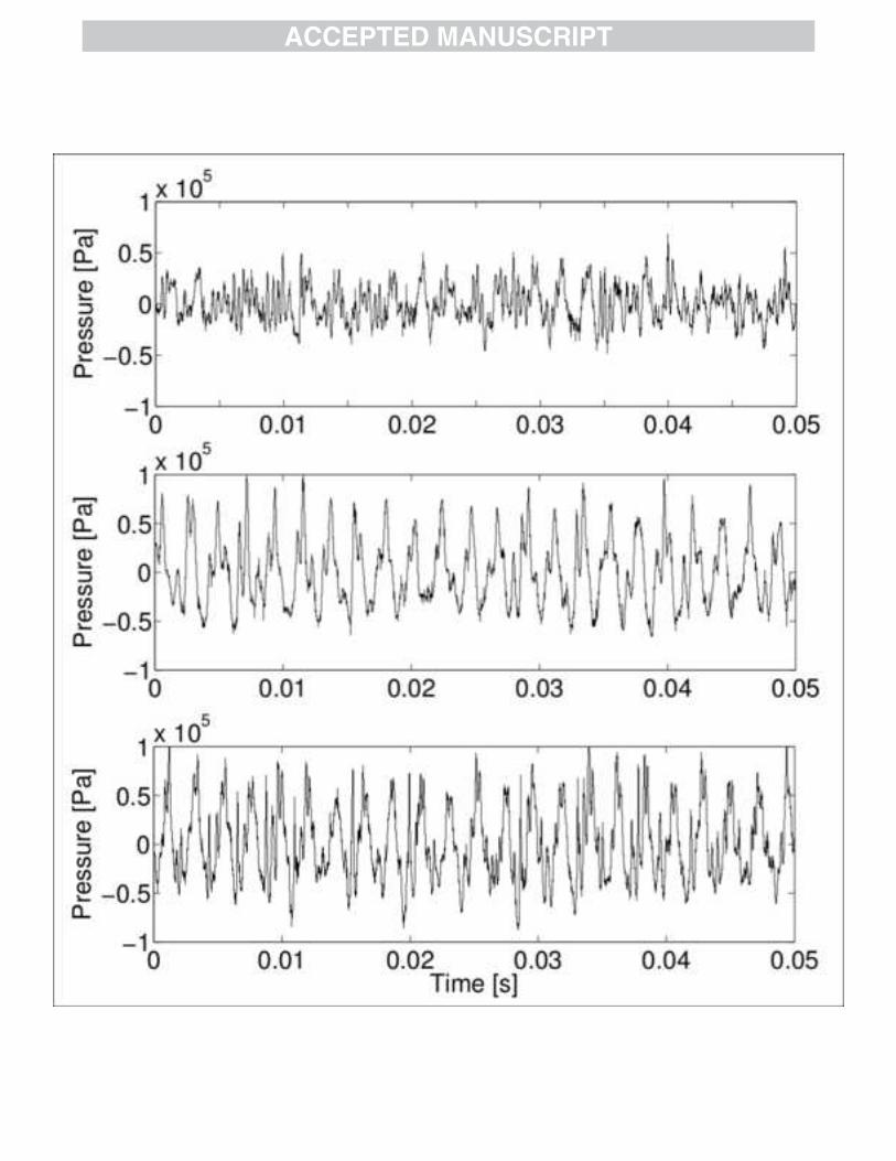
Detailed pressure analysis (Fig. 4) shows, that pressure oscillations at rotational speed 2290 rpm intensively distinguish between the gap size of 3.5 mm (Fig. 4 – upper diagram) and 0.8 mm (Fig. 4 – lower diagram), but the difference between 0.8 mm and 1.5 mm (Fig. 4 – middle diagram) is rather small, which is also noticeable on figure 3 and can be connected with operating in boundary layer conditions. The pressure amplitudes are by 3.5 mm gap size in average of 0.7 bar, while in case of gap size of 0.8 mm the pressure amplitudes raise up to 1.7 bar. Cavitation bubble develops at the point of weakness in the liquid continuum and these points are formed by small gas and vapor inclusions and are so called cavitation nuclei [3]. The number of nuclei tells us at how many places the liquid is weakened and as a consequence exposed for cavitation formation. The more the cavitation nuclei are present, the higher is possibility for cavitation formation. But one must be aware of the fact, that cavitation aggressiveness is also conditional of the liquid properties [27]. Figure 5 presents the comparison of pressures between operation in tap water (at laboratory conditions) and in WAS (at WWTP) at similar conditions. As one can see, the pressure signal differ between the tap water and the WAS. The explanation for the difference lies in the fluid properties. In case of WAS the fluid has more than 10 g per liter of dry (solid) content, which act as cavitation nuclei, where the cavitation bubbles begin to grow. As one can see in case of cavitation in WAS (Figure 5), the pressure signal is stable and the pressure oscillations are approximately the same value. In case of cavitation in tap water (Figure 5) the pressure signal is more random and the pressure oscillations deviate and are in some cases higher than in case of cavitation in WAS. The standard deviation between the pressure oscillations at cavitation in tap water and WAS is approximately the same, and has the value of around 60 kPa. One can conclude that cavitation in case of tap water is more aggressive, but in case of WAS the extent of cavitation is bigger, but no major differences are present. Visual comparison was not able to perform, due to opacity of the WAS.
Figure 6 shows the visualization of the cavitation between stator and rotor teeth. The images on Fig. 6 presents the case for rotational speed of the rotor of 2850 rpm and the distance between the rotor and stator of 0.8 mm. The time step between two images is ¼ ms at recorded frame rate of 8000 fps. On the left side of the images the stator tooth (ST) is seen. The ST kept still, while the rotors tooth (RT) (on the

right side of the images) is moving upward due to rotation of the rotor. The series of images is shown for one passage of the RT by the ST. On image 1, the ST and the RT are aligned and only little cavitation is present. On images 2 and 3 due to free volume expansion the low pressure zone forms in which the cavitation extents, while on image 4 gets the cavitation its full extent. On the image 5, 6 and 7 the free volume between the grooves reduces, which means that the pressure increases and due to pressure recuperation the cavitation extent decreases. On the image 8 the ST and RT are aligned again and the cavitation conditions repeat. Cavitation extent and aggressiveness can be regulated by controlling the distance between the rotor and stator and the rotor's frequency. Cavitation extent is increasing with the rotational speed, while the aggressiveness is increasing mainly with the distance reduction between the rotor and stator and also with the rotational speed increase. Aggressiveness can be parallel compared with the pressure oscillations. Higher pressure oscillations and bigger pressure gradient means more aggressive cavitation, while the extent of cavitation can be reliably determined by visualization.
3.2. Biological analysis Experiments with WAS were performed by three different operating conditions. In the first experiment (Fig. 7 – Test #1) the rotation speed of the rotor was set to 2290 rpm and the distance between RT and ST was 3.5 mm. By first experiment only 10 passes of WAS through the RGHC were performed. In the second experiment (Fig. 7 – Test #2) the rotation speed of the rotor was kept at 2290 rpm, but the distance between the RT and the ST was reduced to 0.8 mm. By the second experiment the WAS was exposed to 20 passes through RGHC. In the third experiment (Fig. 7 – Test #3) the distance between the RT and ST was kept at 0.8 mm, but the rotation speed was increased to 2850 rpm. The samples for biological analysis were taken before the cavitation exposure and after 5, 10 and 20 (by Test #1, after 1, 5 and 10) passes through RGHC. Values of total dry solid content for the samples are 7.9 g/L, 12.4 g/L and 10.4 g/L in case of Test #1, Test #2 and Test #3 respectively. As one can see on figure 7 the SCOD and soluble Kjeldahl nitrogen are increasing with the number of passes through RGHC by all three experiments, which indicates, that more than one passage through the cavitation process is needed for sufficient disintegration. The reduction of the distance between the RT and the ST and the increase of the rotation speed of the rotor contribute to the higher release of the SCOD, which indicates that for the good sludge disintegration an aggressive cavitation is needed. By third experiment (Fig. 7, Test #3) where the most aggressive cavitation of all three cases was performed, the SCOD reached 602 mg/L from initial 45 mg/L in 20 passes through cavitation exposure and the soluable Kjeldahl nitrogen raised from 6.3 mg/L up to 71 mg/L. Kjeldahl nitrogen increases due to release of the nitrogen from the cells, which confirms, that the cavitation has a permanent effect on the sludge, while the SCOD indicates the level of disintegration, which is important for anaerobic digestion and consequently biogas production and sludge residue.
Figure 8 presents the microbiological pictures (100 times magnified) of the WAS before the cavitation exposure and after 20 passes through RGHC by Test #3. On the left image one can see, that there are many big flocs and that the microorganisms are not equally scattered on the surface, while on the right image one can see much smaller flocs and much better dispersion of the microorganisms, which indicates on better disintegration. After the disintegration of the WAS with hydrodynamic cavitation, the two pilot bioreactors were prepared for the biogas production test. The first bioreactor was filled with 15 L of disintegrated WAS

and 181 L of inoculum, which was taken at the outled from the digester and used as bacterial culture for degradation of the substrates by the digestion test. The second bioreactor was used as a reference and was filled with 15 L of reference, non-treated WAS and 181 L of inoculum. The temperature of the bioreactors was kept constant at 40°C for 13 days and during this time the production of biogas was measured. Figure 9 shows the production of the biogas for treated and non-treated WAS for the case of Test #3. After 13 days of digestion the first bioreactor produced 249 L of biogas, while in second bioreactor 221 L of biogas was released. As one can see, the difference of the total biogas production in 13 days between the treated and un-treated WAS was 12.7 % in favor of treated WAS. Disintegration degree (DD) on figure 10 shows the increase of the organic material in the dissolved phase of the sludge due to treatment in comparison with the maximum possible disintegration of the sludge. While the definition of the DD varies between the studies [5, 22, 28-30], we used the following equation for DD calculation: DD [ ]=�SCOD
cav− SCOD
i�/�SCODmax
− SCODi�× 100
The SCOD of pretreated sludge with cavitation is denoted as SCODcav, initial SCOD of untreated sludge is written as SCODi and maximum possible SCOD for the selected sludge as SCODmax. The SCODmax was in this study experimentally measured by mechanical (with mixer) and chemical (with H2SO4 ) treatment at the laboratory conditions. The values of the SCODmax are 660 mg/L, 1050 mg/L and 1023 mg/L for Test #1, Test #2 and Test #3 respectively. 3.3 Economic feasibility Finally, it makes sense to address the question whether the energy gain from added amount of produced biogas surpasses the energy input to RGHC. To evaluate the energy balance of the RGHC for WAS disintegration on municipal WWTPs calculations based on experimental data (sections 2.3 and 3.2) were made. Calculations were made for the case of the presented pilot scale experiment, where 12,7% more biogas was released, when the WAS was treated with RGHC. For the biogas production test 15L of cavitated WAS + 181 L of inoculum was used, where in 13 days 28 L more biogas was produced, compared to the case where the WAS was un-treated. If all of the 196 L of cavitated WAS would be used for biogas production, one can assume that 13×28 L=364 L more biogas would be produced. Based on long term observation at the Domžale-Kamnik WWTP the average caloric value of 1 m3 biogas is 6 kWh, from which 2,2 kWh of electric energy and 2,7 kWh of usable heat (used for required heating of the sludge during the anaerobic process) can be produced (1,1 kWh of heat is useless – waste heat). That means, that from 364 L of extra produced biogas, approximately 800 Wh of electricity and 983 Wh of usable heat could be produced. Since a typical WWTP uses installment of several kW of pumps (11 kW in the case of Domžale-Kamnik WWTP) to transport the sludge, it is our idea the RGHC could also contribute to this, hence only energy for generation of cavitation needs to be supplied by enhanced biogas production. The overall length of the present experiment was about 55min, which means that the electric energy used was 4620 Wh, of which 240 Wh was used for pumping and the rest, 4380 Wh was used for generation of cavitation and losses (this is mostly energy converted to heat of WAS, which is not lost as it is reused to maintain the sludge temperature in the anaerobic digesters). It is clear that the gain in energy during the present campaign does not meet the energy input. However the RGHC did not operate under optimal conditions due to the limitations of the pilot test-rig (this can also be seen from

its characteristics in Fig. 11.) The near optimal flow rate was measured at about 400 L/min in clean water. Also the measurements of amplitude of pressure oscillations are approximately constant between the pilot installation flow rate of 71 L/min and the optimal flow rate of 400 L/min – this in our experience points to the same effect of cavitation at both flow rates. At the optimal flow rate the electrical power consumption was 5800 W of which 1150 W were used for pumping and 4650 W were used for generating of cavitation or were lost. At flow rate 400 L/min less than 10 minutes would be needed to treat 196 L of WAS 20 times, which means that only 775 Wh would additionally be needed for generating cavitation in RGHC. When one compares the result of this simple derivation to the measured energy gain from additionally produced biogas, it is clear that such an operation would be economically feasible. To confirm this reasoning, of course, measurements in real installation are needed – these are planed in the near future. Finally one must be aware that the additional energy input for the WAS disintegration has, besides enhanced biogas production, also other beneficial effects, which can further lower the overall operating costs of the WWTP. These are for example (i) shorter retention times of the WAS in digesters, which means smaller digester volume and consequently lower operating costs; (ii) better digested sludge, for which better dewatering can be achieved, which consequently means lower costs for transport and incineration of the digested sludge. Table 1: Energy consumption and gained energy with RGHC usage.
RGHC
WAS Volume [L] 196
Flowrate [L/min] 71 400
Electric power [W] 5040 5800
Hydraulic power [W] 260 1150
Power for cavitation + losses [W] 4780 4650
El. energy for WAS treatment (20 times) [Wh] 4380 775*
Extra gained biogas [L] 364
El. energy from extra gained biogas [Wh] 800
Heat from extra gained biogas [Wh] 983
* extrapolated from measurements
4. Conclusions
The paper presents a novel rotation generator of hydrodynamic cavitation for WAS disintegration. The study shows that using RGHC for WAS pretreatment leads to better disintegration of the WAS, which directly leads to higher biogas production. The economic feasibility also shows, that the energy consumption of the RGHC could be gained from higher biogas production, due to better disintegration of the WAS. Other effects due to better disintegration of the WAS are: (i) shorter retention time of the WAS in anaerobic digesters, which leads to smaller digester volumes and consequently to lower operating costs and (ii) better digested sludge, which leads to lower costs for its transport and incineration, due to better possible dewatering. All these effects lead to better wastewater management and possible overall reduction of the operating costs for wastewater treatment plants. In the present study we achieved to increase SCOD of WAS from initial 45 mg/L up to 602 mg/L by

only 20 passes through RGHC. The biogas production increased for 12.7 % in case of disintegrating WAS with RGHC. Comparison between the analysis of hydrodynamic and biological results leads to conclusion that cavitation aggressiveness has more important role than cavitation extent by WAS disintegration.

References
[1] M. Dular, O. Coutier-Delgosha, Thermodynamic effects during growth and collapse of a single cavitation bubble, Journal of Fluid Mechanics, 736 (2013) 44-66.
[2] Y.C. Wang, C.E. Brennen, Shock wave development in the collapse of a cloud of bubbles, Cavitation and Multiphase Flow, FED vol. 194 (1994) 15-19.
[3] J.P. Franc, Fundamentals of Cavitation, Kluwer Academic Publishers, 2004.
[4] S. Fujikawa, T. Akamatsu, Effects of the non-equilibrium condensation of vapor on the pressure wave produced by the collapse of the bubble in a liquid, Journal of Fluid Mechanics 97 (1980) 481–512.
[5] S. Pilli, P. Bhunia, S. Yan, R.J. LeBlanc, R.D. Tyagi, R.Y. Surampalli, Ultrasonic pretreatment of sludge: A review, Ultrasonic Sonochemistry, 18 (2011) 1-18.
[6] O. Güven Apul, F. Dilek Sanin, Ultrasonic pretreatment and subsequent anaerobic digestion under different operational conditions, Bioresource Technology, 101 (2010) 8984–8992.
[7] P. Braeutigam, M. Franke, B. Ondruschka, Effect of ultrasound amplitude and reaction time on the anaerobic fermentation of chicken manure for biogas production, Biomass and Bioenergy (2014), article in press.
[8] R. Farooq, F. Rehman, S. Baig, M. Sadique, S. Khan, U. Farooq, A. Rehman, A. Farooq, A. Pervez, M. Hassan, S.F. Shaukat, The effect of ultrasound irradiation on the anaerobic digestion of activated sludge, World Applies Sciences Journal, 6 (2009) 234–237.
[9] A. Gallipoli, C.M. Braguglia, High-frequency ultrasound treatment of sludge: Combined effect of surfactants removal and floc disintegration, Ultrasonic Sonochemistry, 19 (2012) 864–871.
[10] G. Zhang, P. Zhang, J. Gao, Y. Chen, Using acoustic cavitation to improve the bio-activity of activated sludge, Bioresource Technology, 99 (2008) 1497–1502.
[11] S. Arrojo, Y. Benito, A. Martinez Tarifa, A parametrical study of disinfection with hydrodynamic cavitation, Ultrasonic Sonochemistry, 15 (2008) 903–908.
[12] M. Zupanc, T. Kosjek, M. Petkovšek, M. Dular, B. Kompare, B. Širok, Ž. Blaženka, E. Heath, Removal of pharmaceuticals from wastewater by biological processes, hydrodynamic cavitation and UV treatment, Ultrasonic Sonochemistry 20 (2013) 1104–1112.
[13] M. Zupanc, T. Kosjek, M. Petkovšek, M. Dular, B. Kompare, B. Širok, Ž. Blaženka, M. Stražar, E. Heath, Shear-induced hydrodynamic cavitation as a tool for pharmaceutical micropollutants removal from urban wastewater, Ultrasonic Sonochemistry 21 (2014) 1213–1221.
[14] K. Hirooka, R. Asano, A. Yokoyama, M. Okazaki, A. Sakamoto, Y. Nakai, Reduction in excess sludge production in a dairy wastewater treatment plant via nozzle-cavitation treatment: Case study of an on-farm wastewater treatment plant, Bioresource Technology, 100 (2009) 3161-3166.
[15] D. Ghayal, A.B. Pandit, V.K. Rathod, Optimization of biodisel production in a hydrodynamic cavitation reactor using used frying oil, Ultrasonic Sonochemistry, 20 (2013) 322-328.
[16] S. Zhang, P. Zhang, G. Zhang, J. Fan, Y. Zhang, Enhancement of anaerobic sludge digestion by high-pressure homogenization, Bioresource Technology, 118 (2012) 496-501.
[17] M. Franke, P. Braeutigam, Z.L. Wu, Y. Ren, B. Ondruschka, Enhacement of chloroform degradation by the combination of hydrodynamic and acoustic cavitation, Ultrasonic Sonochemistry 18 (2011) 888–894.

[18] P.N. Patil, P.R.Gogate, Degradation of methyl parathion using hydrodynamic cavitation: Effect of operating parameters and intensification using additives, Separation and Purification Technology 95 (2012) 172–179.
[19] M.V. Bagal, P.R. Gogate, Degradation of 2,4-dinitrophenol using a combination of hydrodynamic cavitation, chemical and advanced oxidation process, Ultrasonic Sonochemistry 20 (2013) 1226–1235.
[20] A.G. Chakinala, P.R. Gogate, A.E. Burgess, D.H. Bremmer, Treatment of industrial wastewater effluents using hydrodynamic cavitation and the advanced Fenton process, Ultrasonic Sonochemistry, 15 (2008) 49–54.
[21] G. Xu, S. Chen, J. Shi, S. Wang, G. Zhu, Combination treatment of ultrasound and ozone for improving solunilization and anaerobic biodegradability of waste activated sludge, Journal of Hazardeous Materials, 180 (2010) 340-346.
[22] I. Lee, J.-In Han, The effects of waste-activated sludge pretreatment using hydrodynamic cavitation for methane production, Ultrasonic Sonochemistry, 20 (2013) 1450-1455.
[23] K.K. Jyoti, A.B. Pandit, Hybrid cavitation methods for water disinfection: simultaneous use of chemicals with cavitation, Ultrasonic Sonochemistry, 10 (2003) 255-264.
[24] P.S. Kumar and A.B. Pandit, Modeling Hydrodynamic Cavitation, Chemical Engineering and Technology 22 (1999) 1017-1027.
[25] M. Badve, P. Gogate, A. Pandit, L. Csoka, Hydrodynamic cavitation as a novel approach for wastewater treatment in wood finishing industry, Separ. Purif. Technol. 106 (2013) 15-21.
[26] M. Petkovšek, M. Zupanc, M. Dular, T. Kosjek, E. Heath, B. Kompare, B. Širok, Rotation generator of hydrodynamic cavitation for water treatment, Separ. Purif. Technol. 118 (2013) 415-423.
[27] M. Dular, B. Širok, B. Stoffel, The influence of the gas content of water and the flow velocity on cavitation erosion aggressiveness, Journal of Mechanical Engineering, 51 (2005) 132-145.
[28] T. Benabdallah El-Hadj, J. Dosta, R. Marguez-Serrano, J. Mata-Alvarez, Effect of ultrasound pretreatment in mesophilic and thermophilic anaerobic digestion with emphasis on naphthalene and pyrene removal, Water Research, 41 (2007) 87-94.
[29] K. Nickel, U. Neis, Ultrasonic disintegration of biosolids for improved biodegradation, Ultrasonic Sonochemistry, 14 (2007) 450-455.
[30] S.S. Yang, W.Q. Guo, G.L. Cao, H.S. Zheng, N.Q. Ren, Simultaneous waste activated sludge disintegration and biological hydrogen production using an ozone/ultrasound pretreatment, Bioresource Technology, 124 (2012) 347-354.

Figure captions:
Figure 1: Cavitation generator.
Figure 2: Schematic diagram of experimental set-up (left – Faculty of Mechanical Engineering, right – Domžale-Kamnik WWTP).
Figure 3: Integral pressure analysis.
Figure 4: Pressure analysis at 2290 rpm (gap size: 3.5mm-top diagram, 1.5mm-middle diagram, 0.8mm-bottom diagram)
Figure 5: Pressure analysis at 2850rpm, gap size 0.8mm (top - Faculty of Mechanical Engineering, bottom - Domžale-Kamnik WWTP).
Figure 6: Visualization of cavitation, time step between frames is ¼ ms at 8000 fps.
Figure 7: Soluble COD (left) and soluble Kjeldahl nitrogen (right) at different number of passes through RGHC at different operating conditions.
Figure 8: Microbiological pictures (left – non-treated WAS, right – WAS after 20 passes through RGHC by Test #3).
Figure 9: Biogas production (Test #3).
Figure 10: Degree of disintegration of SCOD at different operating conditions.
Figure 11: RGHC characteristic (p – pressure curve, Pel - electric power curve, Ph – hydraulic power curve).
Table captions:
Table 1: Energy consumption and gained energy with RGHC usage.

HIGHLIGHTS Manuscript title: A novel rotation generator of hydrodynamic cavitation for waste-activated sludge disintegration Research highlights:
• A novel rotation generator of hydrodynamic cavitation is presented. • Experimental measurements on a pilot-scale bioreactor plant. • Generated cavitation has a very strong impact on the disintegration of the waste-activated
sludge. • Presented cavitation generator has a considerable effect on the biogas production increase.
Yours sincerely, Martin Petkovšek (corresponding author) Ljubljana, 10.4.2014 Martin Petkovšek Laboratory for Water and Turbine Machines, Faculty of Mechanical Engineering, University of Ljubljana, Askerceva 6, 1000 Ljubljana Slovenia E-mail: [email protected]


![A novel rotation generator of hydrodynamic cavitation for ... · Locally seen the cavitation is a process of evaporation, gas expansion, condensation and gas compression [1]. The](https://img.dokumen.tips/doc/110x75/5e890c49635a7123df5d7c57/a-novel-rotation-generator-of-hydrodynamic-cavitation-for-locally-seen-the-cavitation.jpg)