Embed Size (px)
Citation preview

This content has been downloaded from IOPscience. Please scroll down to see the full text.
Download details:
IP Address: 140.113.38.11
This content was downloaded on 26/04/2014 at 11:39
Please note that terms and conditions apply.
A novel large displacement electrostatic actuator: pre-stress comb-drive actuator
View the table of contents for this issue, or go to the journal homepage for more
2005 J. Micromech. Microeng. 15 1641
(http://iopscience.iop.org/0960-1317/15/9/005)
Home Search Collections Journals About Contact us My IOPscience
INSTITUTE OF PHYSICS PUBLISHING JOURNAL OF MICROMECHANICS AND MICROENGINEERING
J. Micromech. Microeng. 15 (2005) 1641–1648 doi:10.1088/0960-1317/15/9/005
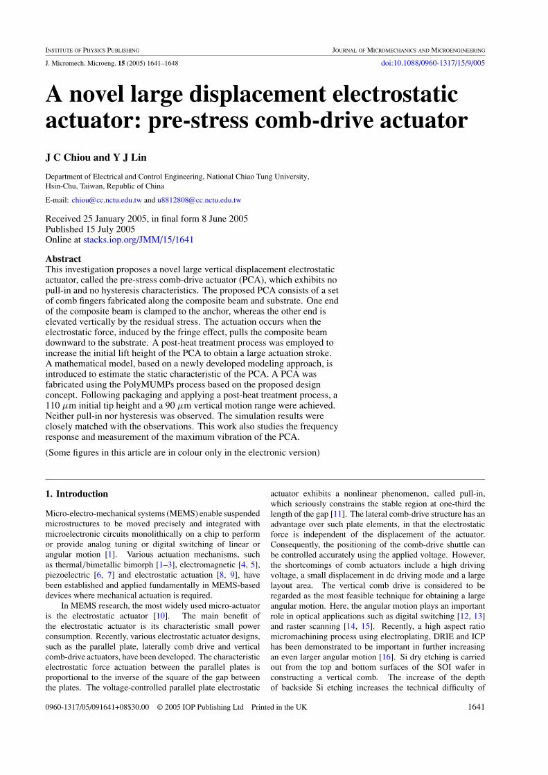
A novel large displacement electrostaticactuator: pre-stress comb-drive actuatorJ C Chiou and Y J Lin
Department of Electrical and Control Engineering, National Chiao Tung University,Hsin-Chu, Taiwan, Republic of China
E-mail: [email protected] and [email protected]
Received 25 January 2005, in final form 8 June 2005Published 15 July 2005Online at stacks.iop.org/JMM/15/1641
AbstractThis investigation proposes a novel large vertical displacement electrostaticactuator, called the pre-stress comb-drive actuator (PCA), which exhibits nopull-in and no hysteresis characteristics. The proposed PCA consists of a setof comb fingers fabricated along the composite beam and substrate. One endof the composite beam is clamped to the anchor, whereas the other end iselevated vertically by the residual stress. The actuation occurs when theelectrostatic force, induced by the fringe effect, pulls the composite beamdownward to the substrate. A post-heat treatment process was employed toincrease the initial lift height of the PCA to obtain a large actuation stroke.A mathematical model, based on a newly developed modeling approach, isintroduced to estimate the static characteristic of the PCA. A PCA wasfabricated using the PolyMUMPs process based on the proposed designconcept. Following packaging and applying a post-heat treatment process, a110 µm initial tip height and a 90 µm vertical motion range were achieved.Neither pull-in nor hysteresis was observed. The simulation results wereclosely matched with the observations. This work also studies the frequencyresponse and measurement of the maximum vibration of the PCA.
(Some figures in this article are in colour only in the electronic version)
1. Introduction
Micro-electro-mechanical systems (MEMS) enable suspendedmicrostructures to be moved precisely and integrated withmicroelectronic circuits monolithically on a chip to performor provide analog tuning or digital switching of linear orangular motion [1]. Various actuation mechanisms, suchas thermal/bimetallic bimorph [1–3], electromagnetic [4, 5],piezoelectric [6, 7] and electrostatic actuation [8, 9], havebeen established and applied fundamentally in MEMS-baseddevices where mechanical actuation is required.
In MEMS research, the most widely used micro-actuatoris the electrostatic actuator [10]. The main benefit ofthe electrostatic actuator is its characteristic small powerconsumption. Recently, various electrostatic actuator designs,such as the parallel plate, laterally comb drive and verticalcomb-drive actuators, have been developed. The characteristicelectrostatic force actuation between the parallel plates isproportional to the inverse of the square of the gap betweenthe plates. The voltage-controlled parallel plate electrostatic
actuator exhibits a nonlinear phenomenon, called pull-in,which seriously constrains the stable region at one-third thelength of the gap [11]. The lateral comb-drive structure has anadvantage over such plate elements, in that the electrostaticforce is independent of the displacement of the actuator.Consequently, the positioning of the comb-drive shuttle canbe controlled accurately using the applied voltage. However,the shortcomings of comb actuators include a high drivingvoltage, a small displacement in dc driving mode and a largelayout area. The vertical comb drive is considered to beregarded as the most feasible technique for obtaining a largeangular motion. Here, the angular motion plays an importantrole in optical applications such as digital switching [12, 13]and raster scanning [14, 15]. Recently, a high aspect ratiomicromachining process using electroplating, DRIE and ICPhas been demonstrated to be important in further increasingan even larger angular motion [16]. Si dry etching is carriedout from the top and bottom surfaces of the SOI wafer inconstructing a vertical comb. The increase of the depthof backside Si etching increases the technical difficulty of
0960-1317/05/091641+08$30.00 © 2005 IOP Publishing Ltd Printed in the UK 1641

J C Chiou and Y J Lin
(a) (b) (c)
Figure 1. The PCA at different driving states; (a) initial state, (b) bias voltage state and (c) critical bias voltage state.
the method [17], and causes problems of alignment and gapexpansion. Notably, a vertical comb-drive actuator cannoteasily achieve a larger deflection angle at a low drivingvoltage.
The advantages of bulk micromachining, a MEMSfabrication technique, are in manufacturing flattermicromirrors, with high stiffness in the vertical directionand greater working space in the out-plane actuation.However, beam stiffness, isotropic/anisotropic bulk etchingand electrical interconnect/isolation are difficult to controlaccurately. Surface micromachining provides a flexiblemechanical and electrical structure. Here, the working/motionspace of various actuators is limited in in-plane actuation orsmall out-plane motion displacement [14]. Chen et al used thestress-induced bending of a composite cantilever beam to raisea vertical mirror mounted on the free end [18]. A cantileverbeam with a length of 1500 µm with a 300 µm verticaldisplacement is developed [18]. Its driving mechanism issimilar to a parallel plate electrostatic actuator which has thedrawback of pull-in, which limits its application to opticaldigital switching. The mechanical stability of the actuatorbecomes crucially essential when it is applied to other MEMSdevices that require analog tuning. Rosa et al proposed anexternal electrode concept that contrasts with the conventionalconcept and frequently employed a parallel plate electrodescheme for the electrostatic actuation of MEMS devices [19].The external electrode configuration allows the operation ofelectrostatic actuators to be controlled over their entire rangeof motion by preventing electrostatic pull-in instability. Itis based on the application of the fringe effect between themoving electrode and the fixed external electrodes. Notably,the shape of the external electrodes seems to be arbitrarilydesigned. However, the fringe effect between the moving andfixed external electrodes is relatively inefficient. Accordingly,the static characteristic criteria in obtaining the actuating forceof the electrostatic actuator are severely limited. Akiyamaet al have demonstrated a comb-shape electrostatic actuatorfor high-speed feedback motion, with which they achievedalmost 1 µm stroke under 50–130 V applied voltage whenthe initial height difference, due to the residual stress, was2 µm [20]. Note that the comb-shape electrostatic actuatorwas fabricated using metal and thick device layer of the SOIwafer that limits the initial height difference.
A novel pre-stress comb-drive actuator is developedto overcome the limitations of the actuation range of theaforementioned electrostatic actuator. The advantages of thepre-stress comb-drive actuator (PCA) include continuity ofmotion (without pull-in or hysteresis) and a large vertical
actuation range. A mathematical model is presented to predictthe static characteristic of the PCA. A PCA was fabricatedusing the PolyMUMPs process based on the proposed designconcepts. The static characteristic, frequency response andmaximum vibration amplitude of the fabricated PCA weremeasured.
2. Principle
Figure 1 schematically depicts a PCA with different drivenstates. The PCA consists of an anchor, a composite beamand a set of comb fingers. These comb fingers, designedalong the composite beam and substrate, acted as the movableand fixed comb fingers. Figure 1(a) shows one end of thecomposite beam, which is clamped to the anchor, whilethe other end is elevated due to the residual stress betweenthe two deposited materials. Notably, the initial lift heightof the PCA can be further enhanced by increasing the residualstress of the composite beam using a post-heat treatmentprocess [18]. When a voltage, V, is applied between themovable and fixed comb, the movable composite beam canbe pulled downward to the substrate by the electrostatic forceinduced by the fringe effect, as shown in figure 1(b). Thetaper-like distances between each movable and fixed comb areobtained from the free end to the fixed end based on the curved-up shape of the composite beam. In the actuating mechanisms,the movable comb fingers that are close to the anchor providethe main actuation force. As the actuation progresses, the retralmovable comb fingers will be pulled down accordingly. Asthe driving voltage is increased, the vertical displacement ofthe free end of the PCA is increased. Notably, the electrostaticforce is constrained when the movable comb finger is closeto the fixed comb finger, independently of the input drivingvoltage. Therefore, the vertical electrostatic force approacheszero as the movable comb finger reaches its equilibriumposition. Figure 1(c) demonstrates that, when a critical biasvoltage is applied between the movable and fixed comb, thePCA will engage with the substrate.
3. Device modeling and simulation
To understand the properties of the PCA, a mathematicalmodel based on composite beam theory, static electric field anddecomposition analysis is used for modeling the static behaviorof the PCA. In addition, a FEM simulator, IntelliSuite R©,was used to calculate the resonant frequencies and thecorresponding solid mode shapes.
1642
A novel large displacement electrostatic actuator: pre-stress comb-drive actuator
(a) (b)
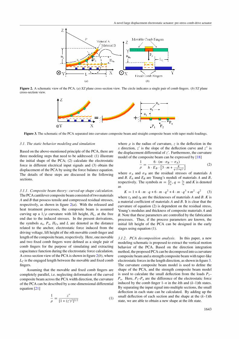
Figure 2. A schematic view of the PCA. (a) XZ plane cross-section view. The circle indicates a single pair of comb fingers. (b) YZ planecross-section view.
Figure 3. The schematic of the PCA separated into curvature composite beam and straight composite beam with taper multi-loadings.
3.1. The static behavior modeling and simulation
Based on the above-mentioned principle of the PCA, there arethree modeling steps that need to be addressed: (1) illustratethe initial shape of the PCA; (2) calculate the electrostaticforce in different electrical input signals and (3) obtain thedisplacement of the PCA by using the force balance equation.The details of these steps are discussed in the followingsections.
3.1.1. Composite beam theory: curved-up shape calculation.The PCA cantilever composite beam consisted of two materialsA and B that possess tensile and compressed residual stresses,respectively, as shown in figure 2(a). With the released andheat treatment processes, the composite beam is assumedcurving up a 1/ρ curvature with lift height, HL, at the freeend due to the induced stresses. In the present derivations,the symbols an, Pn, HFn and L are denoted as the distancerelated to the anchor, electrostatic force induced from thedriving voltage, lift height of the nth movable comb finger andlength of the composite beam, respectively. Here, one movableand two fixed comb fingers were defined as a single pair ofcomb fingers for the purpose of simulating and extractingcapacitance function during the electrostatic force calculation.A cross-section view of the PCA is shown in figure 2(b), whereLC is the engaged length between the movable and fixed combfingers.
Assuming that the movable and fixed comb fingers arecompletely parallel, i.e. neglecting deformation of the curvedcomposite beam across the PCA width direction, the curvatureof the PCA can be described by a one-dimensional differentialequation [21]
1
ρ= z′′
[1 + (z′)2]3/2(1)
where ρ is the radius of curvature, z is the deflection in thex direction, z′ is the slope of the deflection curve and z′′ isthe displacement differential of z′. Furthermore, the curvaturemodel of the composite beam can be expressed by [18]
1
ρ= 6 · (m · σB − σA)
h · EB · [3 · m + K
q·(1+q)2
] (2)
where σ A and σ B are the residual stresses of materials Aand B. EA and EB are Young’s moduli of materials A and B,respectively. The symbols m = EA
EB, q = tA
tBand K is denoted
asK = 1 + 4 · m · q + 6 · m · q2 + 4 · m · q3 + m2 · q2 (3)
where tA and tB are the thicknesses of materials A and B. K isa material coefficient of materials A and B. It is clear that thecurvature of equation (2) is dependent on the residual stress,Young’s modulus and thickness of composite materials A andB. Note that these parameters are controlled by the fabricationprocesses. Thus, if the process parameters are known, theinitial lift height of the PCA can be designed in the earlystages using equation (1).
3.1.2. PCA decomposition analysis. In this paper, a newmodeling schematic is proposed to extract the vertical motionbehavior of the PCA. Based on the direction integrationmethod, the proposed PCA can be decomposed into a curvaturecomposite beam and a strength composite beam with taper-likeelectrostatic forces in the length direction, as shown in figure 3.The curvature composite beam model is used to define theshape of the PCA, and the strength composite beam modelis used to calculate the small deflection from the loads P1–Pn. Here, P1–Pn are the difference of the electrostatic forceinduced by the comb finger 1–n in the kth and (k–1)th states.By separating the input signal into multiple sections, the smalldeflection in each state can be calculated. By adding up thesmall deflection of each section and the shape at the (k–1)thstate, we are able to obtain a new shape at the kth state.
1643

J C Chiou and Y J Lin
Figure 4. The equivalent beam model of the composite beam.
3.1.3. Decomposition of multiple loads. In the mechanicsof material analysis, the deflection of a straight beam withconstant multiple loads can be calculated as follows [21]:
zxn = Pn · x2
6 · Ec · Ic
(3 · an − x)
z′xn = Pn · x
2 · Ec · Ic
(2 · an − x)
, for 0 � x � an (4)
zxn = Pn · a2n
6 · Ec · Ic
(3 · x − an)
z′xn = Pn · a2
n
2 · Ec · Ic
, for an � x � L (5)
where x is the position of the beam, Zxn is the shape of smalldeflection of the strength beam in the position x coming fromthe nth load, Z′
xn is the slope of shape in the position x comingfrom the nth load, an is the position of the nth load, Pn is thedifference of the electrostatic force induced by the comb finger1–n in the kth and (k–1)th states, EC is Young’s modulus ofequivalent single material beam, and IC is the moment of inertiaof the equivalent single material beam. The following sectiondiscusses the equivalent material parameters and electrostaticforce.
3.1.4. Moment of inertia of composite beam. In order toaccurately calculate the moment of inertia of the designedbeam, the composite beam can be recast into a T-shape singlebeam as shown in figure 4.
The material A with width b was replaced by materialB with width α · b, where b is the width of the compositebeam, α is the proportional constant between Young’s moduliof materials A and B, h1 is the distance between the top side ofmaterial A and neutral axis of the T-shape beam and h2 is thedistance between the bottom side of material B and neutral axisof the T-shape beam. The moment of inertia of the T-shapebeam can be expressed as [21]
Ic = 1
12· b · t3
A + b · tA ·(
h1 − tA
2
)2
+1
12· (α · b) · t3
B
+ α · b · tB ·(
h2 − tB
2
)2
(6)
where EC = EB , α = EB
EA, h1 = tA·AA+tB ·AB
AA+AB, h2 = tA + tB − h1
and AA and AB are the cross-section areas of materials A andB, respectively.
3.1.5. Extraction of the electrostatic force. In general, theelectrostatic force of a comb drive can be expressed as [22]
FE = 1
2· N · LC · dC
dz· V 2 (7)
Figure 5. A capacitance versus displacement simulation of a singlepair of comb drives.
where N is the number of comb fingers, LC is the engagedlength of comb fingers, dC/dz is the gradient of capacitanceof comb fingers in the z motion direction and V is the applieddc bias voltage. In a static state case, N, LC and V2 areconstant, and the dC/dz term, the electrostatic force index, isa function of z [23]. In order to extract the function accurately,electromagnetic simulation software AnSoft/Maxwell 2D wasemployed to calculate the comb finger capacitance at differentz positions. By using Matlab simulation software, a sixth-order curve fitting was used to extract the capacitance function,C(z), and the electrostatic force index was obtained by thederivative of the capacitance function. The electrostatic forcecan be rewritten as
FEn(z, V ) = 12 · N · LC · (C0z
6 + C1z5 + C2z
4
+ C3z3 + C4z
2 + C5z1 + C6) · V 2 (8)
where FEn(z, V ) is denoted as the unit electrostatic functionof nth single pair of comb drives in the PCA. Since eachmovable comb finger has different positions, the electrostaticforce contributed from each comb finger is experiencing taper-like behavior from fixed end to free end. Consequently, Pn isdenoted as the difference of the electrostatic force induced bythe comb finger 1–n in the kth and (k–1)th states that can beexpressed as
Pn = FEn(z, Vk) − FEn(z, Vk−1). (9)
Figure 5 shows the simulation result of a single pairof comb drives. The simulation data are calculated byAnSoft/Maxwell 2D, and fit very well by the sixth-orderpolynomial, C(z).
3.1.6. Static simulation. Table 1 presents the static analysisof the PCA with related simulation parameters. The shape ofthe PCA is determined by assuming the initial curvature ofthe composite beam. At a given curvature, a PCA is obtainedwith an initial lift height of 110 µm. The material propertiesin the present simulation were based on the reference from theMUMPS process [24].
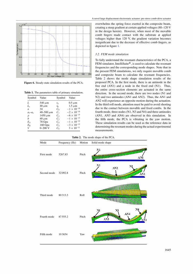
Figure 6 reveals the primary simulation results of the PCAobtained by applying various voltages. Notably, the lift heightis represented by the tip height at the free end of the PCA.Figure 6 clearly indicates that the typical pull-in behaviorof parallel plate electrostatic actuators was not observed inthe present design. Notably, in the early actuation stage, theelectrostatic force obtained from the elevated comb fingers
1644
A novel large displacement electrostatic actuator: pre-stress comb-drive actuator
Figure 6. Steady-state simulation results of the PCA.
Table 1. The parameters table of primary simulation.
Symbol Value Symbol Value
L 540 µm tA 0.5 µmLc 40 µm tB 1.5 µmn 34 C0 −1 × 10⁻¹⁸
a1–an 40–500 µm C1 −2 × 10⁻¹⁶
ρ 1450 µm C2 −6 × 10⁻¹⁵
b 40 µm C3 −1 × 10⁻¹³
EA 78 Gpa C4 −1 × 10⁻¹²
EB 160 Gpa C5 −3 × 10⁻¹²
V 0–200 V C6 3 × 10⁻¹¹
Table 2. The mode shape of the PCA.
Mode Frequency (Hz) Motion Solid mode shape
First mode 5267.83 Pitch
Second mode 32 092.8 Pitch
Third mode 80 313.3 Roll
Fourth mode 87 555.2 Pitch
Fifth mode 10 3654 Yaw
overwhelms the spring force exerted in the composite beam,creating a steep gradient at certain applied voltages (80–120 Vin the design herein). However, when most of the movablecomb fingers made contact with the substrate at appliedvoltages higher than 120 V, the gradient variation becomesinsignificant due to the decrease of effective comb fingers, asdepicted in figure 1.
3.2. FEM mode simulation
To fully understand the resonant characteristics of the PCA, aFEM simulator, IntelliSuite R©, is used to calculate the resonantfrequencies and the corresponding mode shapes. Note that inthe present FEM simulations, we only require movable comband composite beam to calculate the resonant frequencies.Table 2 shows the mode shape simulation results of theproposed PCA. In the first mode, there is an antinode in thefree end (AN1) and a node in the fixed end (N1). Thus,the entire cross-section elements are actuated in the samedirection. In the second mode, there are two nodes (N1 andN2) and two antinodes (AN1 and AN2). Thus, the AN1 andAN2 will experience an opposite motion during the actuation.In the third roll mode, attention must be paid to avoid shortingdue to the contact between movable and fixed combs. In thefourth mode, three nodes (N1, N3 and N4) and three antinodes(AN1, AN3 and AN4) are observed in this simulation. Inthe fifth mode, the PCA is vibrating in the yaw motion.These simulation results can be used as the reference data indetermining the resonant modes during the actual experimentalmeasurements.
1645
J C Chiou and Y J Lin
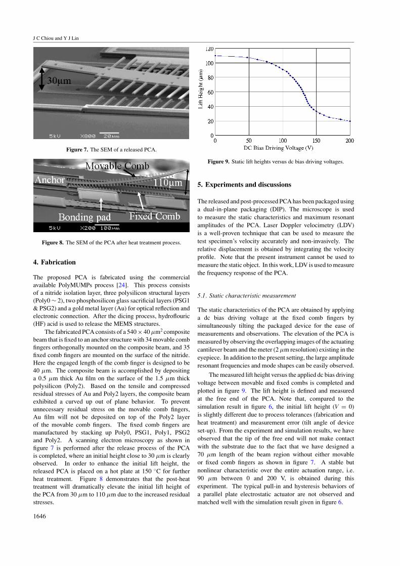
Figure 7. The SEM of a released PCA.
Figure 8. The SEM of the PCA after heat treatment process.
4. Fabrication
The proposed PCA is fabricated using the commercialavailable PolyMUMPs process [24]. This process consistsof a nitride isolation layer, three polysilicon structural layers(Poly0 ∼ 2), two phosphosilicon glass sacrificial layers (PSG1& PSG2) and a gold metal layer (Au) for optical reflection andelectronic connection. After the dicing process, hydroflouric(HF) acid is used to release the MEMS structures.
The fabricated PCA consists of a 540 × 40 µm2 compositebeam that is fixed to an anchor structure with 34 movable combfingers orthogonally mounted on the composite beam, and 35fixed comb fingers are mounted on the surface of the nitride.Here the engaged length of the comb finger is designed to be40 µm. The composite beam is accomplished by depositinga 0.5 µm thick Au film on the surface of the 1.5 µm thickpolysilicon (Poly2). Based on the tensile and compressedresidual stresses of Au and Poly2 layers, the composite beamexhibited a curved up out of plane behavior. To preventunnecessary residual stress on the movable comb fingers,Au film will not be deposited on top of the Poly2 layerof the movable comb fingers. The fixed comb fingers aremanufactured by stacking up Poly0, PSG1, Poly1, PSG2and Poly2. A scanning electron microscopy as shown infigure 7 is performed after the release process of the PCAis completed, where an initial height close to 30 µm is clearlyobserved. In order to enhance the initial lift height, thereleased PCA is placed on a hot plate at 150 ◦C for furtherheat treatment. Figure 8 demonstrates that the post-heattreatment will dramatically elevate the initial lift height ofthe PCA from 30 µm to 110 µm due to the increased residualstresses.
Figure 9. Static lift heights versus dc bias driving voltages.
5. Experiments and discussions
The released and post-processed PCA has been packaged usinga dual-in-plane packaging (DIP). The microscope is usedto measure the static characteristics and maximum resonantamplitudes of the PCA. Laser Doppler velocimetry (LDV)is a well-proven technique that can be used to measure thetest specimen’s velocity accurately and non-invasively. Therelative displacement is obtained by integrating the velocityprofile. Note that the present instrument cannot be used tomeasure the static object. In this work, LDV is used to measurethe frequency response of the PCA.
5.1. Static characteristic measurement
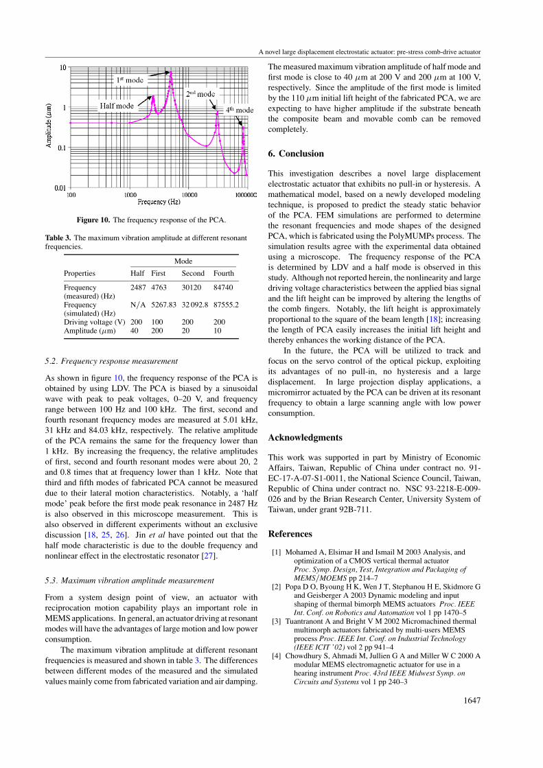
The static characteristics of the PCA are obtained by applyinga dc bias driving voltage at the fixed comb fingers bysimultaneously tilting the packaged device for the ease ofmeasurements and observations. The elevation of the PCA ismeasured by observing the overlapping images of the actuatingcantilever beam and the meter (2 µm resolution) existing in theeyepiece. In addition to the present setting, the large amplituderesonant frequencies and mode shapes can be easily observed.
The measured lift height versus the applied dc bias drivingvoltage between movable and fixed combs is completed andplotted in figure 9. The lift height is defined and measuredat the free end of the PCA. Note that, compared to thesimulation result in figure 6, the initial lift height (V = 0)is slightly different due to process tolerances (fabrication andheat treatment) and measurement error (tilt angle of deviceset-up). From the experiment and simulation results, we haveobserved that the tip of the free end will not make contactwith the substrate due to the fact that we have designed a70 µm length of the beam region without either movableor fixed comb fingers as shown in figure 7. A stable butnonlinear characteristic over the entire actuation range, i.e.90 µm between 0 and 200 V, is obtained during thisexperiment. The typical pull-in and hysteresis behaviors ofa parallel plate electrostatic actuator are not observed andmatched well with the simulation result given in figure 6.
1646
A novel large displacement electrostatic actuator: pre-stress comb-drive actuator
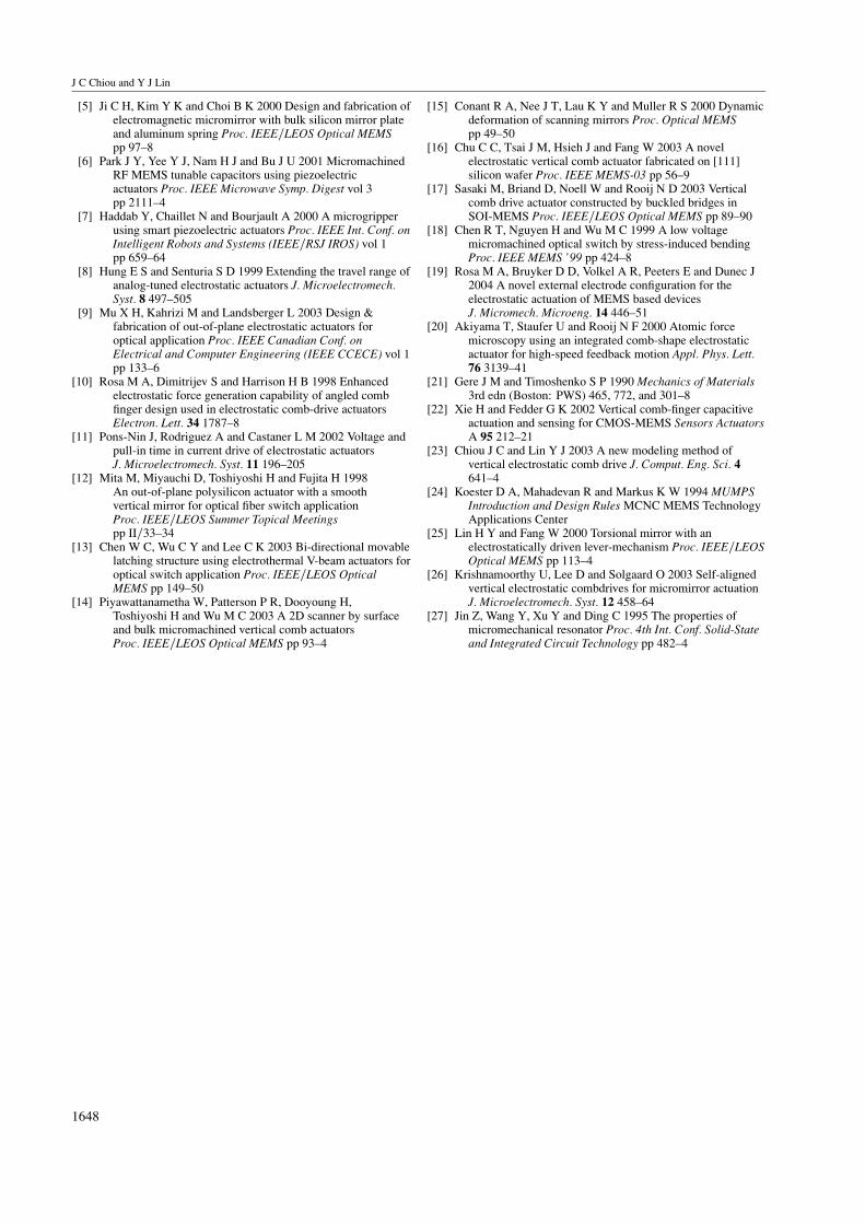
Figure 10. The frequency response of the PCA.
Table 3. The maximum vibration amplitude at different resonantfrequencies.
Mode
Properties Half First Second Fourth
Frequency 2487 4763 30120 84740(measured) (Hz)Frequency N/A 5267.83 32 092.8 87555.2(simulated) (Hz)Driving voltage (V) 200 100 200 200Amplitude (µm) 40 200 20 10
5.2. Frequency response measurement
As shown in figure 10, the frequency response of the PCA isobtained by using LDV. The PCA is biased by a sinusoidalwave with peak to peak voltages, 0–20 V, and frequencyrange between 100 Hz and 100 kHz. The first, second andfourth resonant frequency modes are measured at 5.01 kHz,31 kHz and 84.03 kHz, respectively. The relative amplitudeof the PCA remains the same for the frequency lower than1 kHz. By increasing the frequency, the relative amplitudesof first, second and fourth resonant modes were about 20, 2and 0.8 times that at frequency lower than 1 kHz. Note thatthird and fifth modes of fabricated PCA cannot be measureddue to their lateral motion characteristics. Notably, a ‘halfmode’ peak before the first mode peak resonance in 2487 Hzis also observed in this microscope measurement. This isalso observed in different experiments without an exclusivediscussion [18, 25, 26]. Jin et al have pointed out that thehalf mode characteristic is due to the double frequency andnonlinear effect in the electrostatic resonator [27].
5.3. Maximum vibration amplitude measurement
From a system design point of view, an actuator withreciprocation motion capability plays an important role inMEMS applications. In general, an actuator driving at resonantmodes will have the advantages of large motion and low powerconsumption.
The maximum vibration amplitude at different resonantfrequencies is measured and shown in table 3. The differencesbetween different modes of the measured and the simulatedvalues mainly come from fabricated variation and air damping.
The measured maximum vibration amplitude of half mode andfirst mode is close to 40 µm at 200 V and 200 µm at 100 V,respectively. Since the amplitude of the first mode is limitedby the 110 µm initial lift height of the fabricated PCA, we areexpecting to have higher amplitude if the substrate beneaththe composite beam and movable comb can be removedcompletely.
6. Conclusion
This investigation describes a novel large displacementelectrostatic actuator that exhibits no pull-in or hysteresis. Amathematical model, based on a newly developed modelingtechnique, is proposed to predict the steady static behaviorof the PCA. FEM simulations are performed to determinethe resonant frequencies and mode shapes of the designedPCA, which is fabricated using the PolyMUMPs process. Thesimulation results agree with the experimental data obtainedusing a microscope. The frequency response of the PCAis determined by LDV and a half mode is observed in thisstudy. Although not reported herein, the nonlinearity and largedriving voltage characteristics between the applied bias signaland the lift height can be improved by altering the lengths ofthe comb fingers. Notably, the lift height is approximatelyproportional to the square of the beam length [18]; increasingthe length of PCA easily increases the initial lift height andthereby enhances the working distance of the PCA.
In the future, the PCA will be utilized to track andfocus on the servo control of the optical pickup, exploitingits advantages of no pull-in, no hysteresis and a largedisplacement. In large projection display applications, amicromirror actuated by the PCA can be driven at its resonantfrequency to obtain a large scanning angle with low powerconsumption.
Acknowledgments
This work was supported in part by Ministry of EconomicAffairs, Taiwan, Republic of China under contract no. 91-EC-17-A-07-S1-0011, the National Science Council, Taiwan,Republic of China under contract no. NSC 93-2218-E-009-026 and by the Brian Research Center, University System ofTaiwan, under grant 92B-711.
References
[1] Mohamed A, Elsimar H and Ismail M 2003 Analysis, andoptimization of a CMOS vertical thermal actuatorProc. Symp. Design, Test, Integration and Packaging ofMEMS/MOEMS pp 214–7
[2] Popa D O, Byoung H K, Wen J T, Stephanou H E, Skidmore Gand Geisberger A 2003 Dynamic modeling and inputshaping of thermal bimorph MEMS actuators Proc. IEEEInt. Conf. on Robotics and Automation vol 1 pp 1470–5
[3] Tuantranont A and Bright V M 2002 Micromachined thermalmultimorph actuators fabricated by multi-users MEMSprocess Proc. IEEE Int. Conf. on Industrial Technology(IEEE ICIT ’02) vol 2 pp 941–4
[4] Chowdhury S, Ahmadi M, Jullien G A and Miller W C 2000 Amodular MEMS electromagnetic actuator for use in ahearing instrument Proc. 43rd IEEE Midwest Symp. onCircuits and Systems vol 1 pp 240–3
1647
J C Chiou and Y J Lin
[5] Ji C H, Kim Y K and Choi B K 2000 Design and fabrication ofelectromagnetic micromirror with bulk silicon mirror plateand aluminum spring Proc. IEEE/LEOS Optical MEMSpp 97–8
[6] Park J Y, Yee Y J, Nam H J and Bu J U 2001 MicromachinedRF MEMS tunable capacitors using piezoelectricactuators Proc. IEEE Microwave Symp. Digest vol 3pp 2111–4
[7] Haddab Y, Chaillet N and Bourjault A 2000 A microgripperusing smart piezoelectric actuators Proc. IEEE Int. Conf. onIntelligent Robots and Systems (IEEE/RSJ IROS) vol 1pp 659–64
[8] Hung E S and Senturia S D 1999 Extending the travel range ofanalog-tuned electrostatic actuators J. Microelectromech.Syst. 8 497–505
[9] Mu X H, Kahrizi M and Landsberger L 2003 Design &fabrication of out-of-plane electrostatic actuators foroptical application Proc. IEEE Canadian Conf. onElectrical and Computer Engineering (IEEE CCECE) vol 1pp 133–6
[10] Rosa M A, Dimitrijev S and Harrison H B 1998 Enhancedelectrostatic force generation capability of angled combfinger design used in electrostatic comb-drive actuatorsElectron. Lett. 34 1787–8
[11] Pons-Nin J, Rodriguez A and Castaner L M 2002 Voltage andpull-in time in current drive of electrostatic actuatorsJ. Microelectromech. Syst. 11 196–205
[12] Mita M, Miyauchi D, Toshiyoshi H and Fujita H 1998An out-of-plane polysilicon actuator with a smoothvertical mirror for optical fiber switch applicationProc. IEEE/LEOS Summer Topical Meetingspp II/33–34
[13] Chen W C, Wu C Y and Lee C K 2003 Bi-directional movablelatching structure using electrothermal V-beam actuators foroptical switch application Proc. IEEE/LEOS OpticalMEMS pp 149–50
[14] Piyawattanametha W, Patterson P R, Dooyoung H,Toshiyoshi H and Wu M C 2003 A 2D scanner by surfaceand bulk micromachined vertical comb actuatorsProc. IEEE/LEOS Optical MEMS pp 93–4
[15] Conant R A, Nee J T, Lau K Y and Muller R S 2000 Dynamicdeformation of scanning mirrors Proc. Optical MEMSpp 49–50
[16] Chu C C, Tsai J M, Hsieh J and Fang W 2003 A novelelectrostatic vertical comb actuator fabricated on [111]silicon wafer Proc. IEEE MEMS-03 pp 56–9
[17] Sasaki M, Briand D, Noell W and Rooij N D 2003 Verticalcomb drive actuator constructed by buckled bridges inSOI-MEMS Proc. IEEE/LEOS Optical MEMS pp 89–90
[18] Chen R T, Nguyen H and Wu M C 1999 A low voltagemicromachined optical switch by stress-induced bendingProc. IEEE MEMS ’99 pp 424–8
[19] Rosa M A, Bruyker D D, Volkel A R, Peeters E and Dunec J2004 A novel external electrode configuration for theelectrostatic actuation of MEMS based devicesJ. Micromech. Microeng. 14 446–51
[20] Akiyama T, Staufer U and Rooij N F 2000 Atomic forcemicroscopy using an integrated comb-shape electrostaticactuator for high-speed feedback motion Appl. Phys. Lett.76 3139–41
[21] Gere J M and Timoshenko S P 1990 Mechanics of Materials3rd edn (Boston: PWS) 465, 772, and 301–8
[22] Xie H and Fedder G K 2002 Vertical comb-finger capacitiveactuation and sensing for CMOS-MEMS Sensors ActuatorsA 95 212–21
[23] Chiou J C and Lin Y J 2003 A new modeling method ofvertical electrostatic comb drive J. Comput. Eng. Sci. 4641–4
[24] Koester D A, Mahadevan R and Markus K W 1994 MUMPSIntroduction and Design Rules MCNC MEMS TechnologyApplications Center
[25] Lin H Y and Fang W 2000 Torsional mirror with anelectrostatically driven lever-mechanism Proc. IEEE/LEOSOptical MEMS pp 113–4
[26] Krishnamoorthy U, Lee D and Solgaard O 2003 Self-alignedvertical electrostatic combdrives for micromirror actuationJ. Microelectromech. Syst. 12 458–64
[27] Jin Z, Wang Y, Xu Y and Ding C 1995 The properties ofmicromechanical resonator Proc. 4th Int. Conf. Solid-Stateand Integrated Circuit Technology pp 482–4
1648