Embed Size (px)
Citation preview

Progress In Electromagnetics Research Letters, Vol. 59, 101–107, 2016
A Novel Compact Feeding Network for Array Antenna
Pejman Mohammadi*, Asrin Piroutiniya, and Mohamad Hosein Rasekhmanesh
Abstract—A novel feeding network is investigated both theoretically and experimentally. The proposedsystem with combination of a Wilkinson power divider and two branch-Line couplers is established. Theoutput signals of the system have the same amplitude and 90 phase difference with each other. Thesize reduction technique is applied to minimize the physical size of the proposed network. In thistechnique, the ground of the structure is defected, and distributed capacitors and inductors are addedto empty space of the branch-line couplers. Moreover, meandered lines are used in order to match theoutput impedance of the Wilkinson power divider arms and reduce its size. The initial design realizedin 2.5GHz shows the fractional bandwidth of 24%. Then a miniaturized structure is fabricated with42% smaller size than the main structure while it shows similar electrical performance. For both cases,measurement and simulation results are in good agreement with each other.
1. INTRODUCTION
The demand on the development of microwave compact components, such as couplers and power dividersin communication systems, has been increased, recently. These kinds of devices play an important rolein today’s communications systems. In order to reach the requirements of telecommunication systems,various techniques and methods have been used to create different types of feeding networks such assequential rotation and series-parallel feeding network and feeding networks based in CORPS, Butlermatrix, etc. [1, 2–17]. In [2], a feeding network consists of seven quarter-wavelength transformers linkedtogether in a sequential rotation manner with alternative parallel and series connection to form a front-port network. In [3], a microstrip-feed network is presented which has a 180 ring hybrid coupler, two90 hybrid (branch-line) couplers and a delayed line on the topside of the antenna. A meta-lines basedfeeding network is also investigated in [4] that consists of two anti-parallel quadrature power splittersconnected by a 180 out-of-phase power splitter. The Butler matrix, another type of feeding network,is a corporate multiple beam feed. Butler matrix is usually designed with an equal number of input(beam) and output (antenna) ports (N × N) [16].
In this project, a system which has four outputs with the same magnitude and 90 phase-differenceis presented. The proposed structure consists of two branch-line quadrature hybrid couplers whichare connected to each other by a Wilkinson power divider. A hybrid branch-line coupler shows 90
phase differences between output signals with equal amplitudes. These features make it a very usefulcomponent. On the other hand, power divider is a well-known three-port device which gives two equaloutputs and provides high isolation between outputs [5]. In addition, all of its ports can be matched.As depicted in Fig. 1, a power divider produces two outputs with same amplitude and 180 phasedifference. Output powers of a power divider are applied to couplers. Each coupler has two outputswith 90 phase-difference. The first coupler receives a power with 0 phase and divides it into two equalpowers with 0 and 90 phases, and the second one converts 180 input power to two outputs with 180
and 270 phases. So a network with one input and four outputs is designed.
Received 10 February 2016, Accepted 21 March 2016, Scheduled 8 April 2016* Corresponding author: Pejman Mohammadi ([email protected]).The authors are with the Islamic Azad University Urmia Branch, Urmia, Iran.

102 Mohammadi, Piroutiniya, and Rasekhmanesh
Table 1. Dimension of the structure in Fig. 2(a) (mm).
symbol value symbol value symbol value
L1 7.1 L12 3.9 d 15.4
L2 17.5 L13 2.8 e 7.7
L3 17.5 L14 3 W1 1.1
L4 16.6 L15 2 W2 1.1
L5 17.5 L16 6.7 W3 2
L6 13.7 L17 0.27 W4 1.1
L7 3 L19 4.6 W5 1.1
L8 4.1 a 72.2 W6 0.6
L9 4.1 b 31.7 W7 0.6
L10 4.1 c 28.8 W8 1.6
L11 4.1 L20 6
Table 2. Dimension of the structure in Fig. 3 and Fig. 4 (mm).
symbol value symbol value symbol value
d1 7.1 t2 1.1 x19 0.4
d2 11 t3 2 x20 2.2
d3 6 t4 0.9 x21 0.75
d4 11 t5 1.66 x22 1.1
d5 3.2 t6 0.58 x23 1.3
d6 5 t7 1.08 x24 3.95
d7 4.48 t8 0.58 x25 0.55
d8 1.7 x1 3.75 x26 2.8
d9 2.7 x2 1.1 x27 2.7
d10 1.7 x3 1.35 G1 3.55
d11 5.5 x4 0.221 G2 6.19
d12 1.5 x5 0.8 G3 3.44
d13 4 x6 0.75 G4 6.04
d14 4.4 x7 2.6 G5 7.64
d15 5.84 x8 2.2 G6 7.84
d16 2.08 x9 0.6 G7 6.34
d17 3.2 x10 0.2 g1 2.2
d18 5 x11 0.2 g2 0.75
d19 0.55 x12 0.2 g3 0.15
k 54.8 x13 0.4 g4 0.4
n 21.2 x14 0.6 g5 0.2
m 25.2 x15 0.429 g6 2
p 12.4 x16 0.4 g7 0.2
s 8.2 x17 1.3 g8 0.6
t1 1.1 x18 1.8 g9 0.4
g10 0.2

Progress In Electromagnetics Research Letters, Vol. 59, 2016 103
Figure 1. Block diagram of proposed structure.
2. DESIGN PROCEDURE
The layout of the feeding network is shown in Fig. 2(a). These couplers and power divider are madeof microstrip lines with different impedances. A branch-line hybrid coupler has four λ
4 transmissionlines wherein one pair has characteristic impedances of 35.4Ω and the other pair has 50Ω characteristicimpedances. In this structure, two couplers are connected to output arms of the power divider. In fact,the power divider gives the signals with equal amplitudes and 180 phase differences to couplers. Twobranch-line couplers have been used for dividing the outputs of the power into four equal outputs withthe relative phases of 0, 90, 180, 270.
The substrate used is Ro4003 with a thickness of 0.508mm, relative dielectric constant of ϵr = 3.55
(b)(a)
Figure 2. (a) Configuration of proposed system. (b) Wilkinson power divider with 180 phase difference.
Figure 3. Bottom of the miniaturized structure.
104 Mohammadi, Piroutiniya, and Rasekhmanesh
and tan δ = 0.0027. In most cases, power dividers provide equal amplitude and 0 phase difference.In Wilkinson power divider, outputs are also in phase. In this article, a Wilkinson power divider with180 phase difference in outputs is presented (Fig. 2(b)). Path 1 is about 1.1mm longer and 0.6mmwider than path 2 (in l2 section). The arms of the proposed power divider in the shown part (l2) havedifferent lengths and widths, which result in 180 phase difference. Based on θ = βL, altering L changesθ, also changing W which affect Z0 and result in 180 phase difference. Finally, both outputs have about50Ω±1 impedance. The length and width of l2 do not affect the impedance matching because l2 is verysmall in size, and it just alters the phase. So by changing both length and width, 180 phase differenceis achieved. The amount of width and length are achieved by optimization.
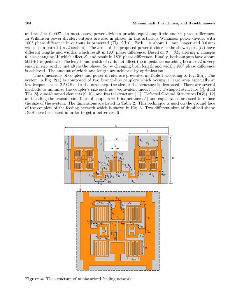
The dimensions of couplers and power divider are presented in Table 1 according to Fig. 2(a). Thesystem in Fig. 2(a) is composed of two branch-line couplers which occupy a large area especially atlow frequencies as 2.5GHz. In the next step, the size of the structure is decreased. There are severalmethods to minimize the coupler’s size such as π-equivalent model [5, 6], T-shaped structure [7], dualTLs [8], quasi-lumped elements [9, 10], and fractal structure [11]. Defected Ground Structure (DGS) [12]and loading the transmission lines of couplers with inductance (L) and capacitance are used to reducethe size of the system. The dimensions are listed in Table 2. This technique is used on the ground faceof the couplers of the feeding network which is shown in Fig. 3. Two different sizes of dumbbell shapeDGS have been used in order to get a better result.
Figure 4. The structure of miniaturized feeding network.

Progress In Electromagnetics Research Letters, Vol. 59, 2016 105
According to the formulas below, vp (Phase velocity) decreases by increasing L (inductance perunit length) and C (capacitance per unit length). The values of L and C must be increased with thesame ratio in order to keep the value of Z0 constant. The wavelength λ is also decreased with thementioned condition, and the size reduction will be achieved.
λ =vpf
(1)
vp =1√LC
(2)
Z0 =
√L
C(3)
By using these two methods, the size of the feeding network is decreased about 42%. The miniaturizedstructure is indicated in Fig. 4. Using a meander microstrip-line is a way to make the whole sizeof a system compact [13]. The size reduction of the Wilkinson power divider was achieved byfolding the quarter-wave transmission lines into tightly coupled meander line. The first one occupies15.4mm × 21.5mm, and the second one occupies 15.4mm × 13.1mm which shows nearly 40% sizereduction. Because of the space needed for attaching the connectors, further size reduction is impossible.
(e)
(a) (b)
(c) (d)
Figure 5. The first structure S-parameters, (a) magnitude simulation results, (b) magnitudemeasurement results, (c) phase simulation results, (d) phase measurement results, (e) isolation betweenports.
3. MEASUREMENT AND SIMULATION RESULTS
Scattering parameters are measured over the frequency range from 1.5GHz to 3.5GHz. Each arm of thementioned power divider has an impedance of 50 ohms and equal length that connected to the inputs ofthe couplers, with 50 ohms impedance which is needed for impedance matching. Both feeding networks

106 Mohammadi, Piroutiniya, and Rasekhmanesh
have fractional bandwidth of 24%. Fig. 5 shows the simulation and measurement results of the firststructure. Input return loss of the main network is less than −20 dB in both measured and simulatedresults. There are acceptable isolations between output ports as shown in Fig. 5(e). The main outputlevel is about −6 dB, and phases of outputs are 136.5, 46.6, −42.2 and −133.9, respectively, whichshow about 90 phase differences. Each coupler of the main network occupies 19.7mm×20.6mm. In thesecond network, a size reduction about 42% is achieved. When the reduction techniques are used, thesize of each coupler reaches 13.2mm× 14.3mm. According to Fig. 6, the small-sized structure has theoutputs of nearly −6 dB, and the phases of outputs are 164.7, 74.6, −16.1, −105.5. The measuredphases are 126.5, 43, −43.3, −129.6 at 2.5GHz that show about ±6 phase error. The return lossof input is better than −20 dB. Isolation ports of the system have reasonable responses in measurementabout −16 dB. Finally, the top of the fabricated structures and bottom of them are illustrated in Fig. 7and Fig. 8, respectively.
(e)
(a) (b)
(c) (d)
Figure 6. The results of the miniaturized structure S-parameters, (a) magnitude simulation results,(b) magnitude measurement results, (c) phase simulation results, (d) phase measurement results,(e) isolation between ports.
Figure 7. Top of the proposed structures. Figure 8. Bottom of the proposed feedingnetworks.

Progress In Electromagnetics Research Letters, Vol. 59, 2016 107
4. CONCLUSION
In this paper, a novel reduced-size feeding network is presented. The size reduction is achieved in thelight of the DGS, and inductance and capacitance per unit length increment is 42%. This new formis established with a Wilkinson power divider and two branch-line couplers. The measurement resultsshow four outputs with the same magnitudes and 90 phase differences. The fractional bandwidth isabout 24% (2.2GHz–2.8GHz). Therefore, the proposed structure is a suitable solution for an arrayantenna feeding network.
REFERENCES
1. Huang, J., “A Ka-band circularly polarized high-gain microstrip array antenna,” IEEETransactions on Antennas and Propagation, Vol. 43, No. 1, 113–116, Jan. 1995.
2. Maddio, S., “A compact wideband circularly polarized antenna array for C-band applications,”IEEE Antennas and Wireless Propagation Letters, Vol. 14, 1081–1084, Dec. 2015.
3. Mohammadi, P. and V. Rafii, “High gain and broadband circularly polarized square slot antennaarray,” Progress In Electromagnetics Research Letters, Vol. 43, 105–113, 2013.
4. Chung, K. L., “High-performance circularly polarized antenna array using metamaterial-line basedfeed network,” IEEE Transactions on Antennas and Propagation, Vol. 61, No. 12, 6233–6237,Dec. 2013.
5. Pozar, D. M., Microwave Engineering, John Wiley & Sons Press, 2005.
6. Tang, C. W. and M. G. Chen, “Miniaturized microstrip branch-line couplers with the approach ofp-model,” Microw. Opt. Tech. Lett., Vol. 50, No. 2, 314–316, 2008.
7. Liao, S., P. T. Sun, N. C. Chin, and J. T. Peng, “A novel compact-size branch-line coupler,” IEEEMicrow. Wirel. Compon. Lett., Vol. 15, No. 9, 588–509, 2005.
8. Tang, C. W., M. G. Chen, and C. H. Tsai, “Miniaturization of microstrip branch-line coupler withdual transmission lines,” IEEE Microw. Wirel. Compon. Lett., Vol. 18, No. 3, 185–187, 2008.
9. Liao, S. and J. T. Peng, “Compact planar microstrip branch-line couplers using the quasi-lumpedelements approach with nonsymmetrical and symmetrical T-shaped structure,” IEEE Trans.Microw. Theory Tech., Vol. 54, No. 9, 3508–3514, 2006.
10. Wang, C. W., T. G. Ma, and C. F. Yang, “A new planar artificial transmission line and itsapplications to a miniaturized Butler matrix,” IEEE Trans. Microw. Theory Tech., Vol. 55, No. 12,2792–2801, 2007.
11. Ghali, H. and T. A. Moselhy, “Miniaturized fractal rat-race, branch-line, and coupled-line hybrids,”IEEE Trans. Microw. Theory Tech., Vol. 52, No. 11, 2513—2520, 2004.
12. Eslamloo, M. K., P. Mohammadi, and M. Khoubrou, “Miniaturized wideband branch-line hybridcoupler with capacitive effect and defected ground structure (DGS),” Indian Journal of Scienceand Technology, Vol. 8, No. 35, December 2015.
13. Esa, M., N. Philip, I. P. Pohan, and N. A. Murad, “Miniaturized microwave meander coupled-linetwo-way wilkinson power divider,” International Symposium on Antennas and Propagation-ISAP,2006.
14. Betancourt, D. and C. Del Ro, “Designing feeding networks with CORPS: Coherently radiatingperiodic structures,” Microwave and Optical Technology Letters, Vol. 48, No. 8, August 2006.
15. Panduro, M. A., “Design of beam-forming Networks for Scannable multi-beam antenna arraysusing CORPS,”. Progress In Electromagnetics Research, Vol. 84, 173–188, 2008.
16. Fakoukakis, F. E. and G. A. Kyriacou, “Novel nolen matrix based beamforming networks for series-fed low SLL multibeam antennas,” Progress In Electromagnetics Research B, Vol. 51, 33–64, 2013.
17. Gruszczyski, S., K. Wincza, and K. Sachse, “Reduced sidelobe four-beamN -element antenna arraysfed by 4N butler matrices,” IEEE Antennas and Wireless Propagation Letters, Vol. 5, 2006.


![A Novel UWB Vivaldi Antenna Array for Radar Applications · odal Vivaldi antenna (AVA) provides more compact size and lower reflections from the feeding structure than TSA [4]. It](https://img.dokumen.tips/doc/110x75/5e8aee74c451793b4a5d01da/a-novel-uwb-vivaldi-antenna-array-for-radar-applications-odal-vivaldi-antenna-ava.jpg)