Embed Size (px)
Citation preview

A new sharp-crease bending element for folding and wrinkling surfaces andvolumes
Saket Patkar∗
Stanford UniversityNing Jin∗
Stanford UniversityRonald Fedkiw∗
Stanford UniversityIndustrial Light & Magic
Figure 1: A knife-pleated skirt fixed on a rotating stand rises up as the stand rotates faster. Note the sharp-creases at the pleats that areachieved by our method. (11700 initial triangles, 16380 triangles after running the virtual node algorithm)
Abstract
We present a novel sharp-crease bending element for the foldingand wrinkling of surfaces and volumes. Based on a control curvespecified by an artist or derived from internal stresses of a simula-tion, we create a piecewise linear curve at the resolution of the com-putational mesh. Then, the key idea is to cut the object along thecurve using the virtual node algorithm creating new degrees of free-dom, while subsequently reattaching the resulting pieces eliminat-ing the translational degrees of freedom so that adjacent pieces mayonly rotate or bend about the cut. Motivated by an articulated rigidbody framework, we utilize the concepts of pre-stabilization andpost-stabilization in order to enforce these reattachment constraints.Our cuts can be made either razor sharp or relatively smooth via theuse of bending springs. Notably, our sharp-crease bending elementscan not only be used to create pleats in cloth or folds in paper butalso to create similar buckling in volumetric objects. We illustratethis with examples of forehead wrinkles and nasolabial folds forfacial animation. Moreover, our sharp-crease bending elements re-
∗e-mail: {patkar,njin19,fedkiw}@cs.stanford.edu
quire minimal extra simulation time as compared to the underlyingmesh, and tend to reduce simulation times by an order of magnitudewhen compared to the alternative of mesh refinement.
CR Categories: I.3.3 [Computer Graphics]: Three-DimensionalGraphics and Realism—Animation
Keywords: folding, buckling, creasing, facial wrinkles
1 Introduction
Sharp folds and wrinkles are important features in the simulation ofdeformable bodies. While one can certainly achieve these effectsdirectly from the underlying physics model, a very high resolutionmesh is often required. And even in cases where the mesh resolu-tion is sufficient, the mesh must be constructed so that its degreesof freedom align with the desired folds. Alternatively, one couldcreate separate meshes with material on each side of the fold orwrinkle, and subsequently join or sock (see [Goulekas 2001]) themtogether with various ad hoc constraints. While this may work wellin certain scenarios such as the boundaries between large muscleson the Hulk, it is sub-optimal for wrinkles or folds that begin and/orend organically at various places within the material such as “smilelines” (nasolabial folds) which occur within the facial fat of a char-acter’s cheek or the wrinkles on the forehead.
Creating separate meshes is attractive when it is possible to do sobecause one could guarantee good mesh quality and fast simulation
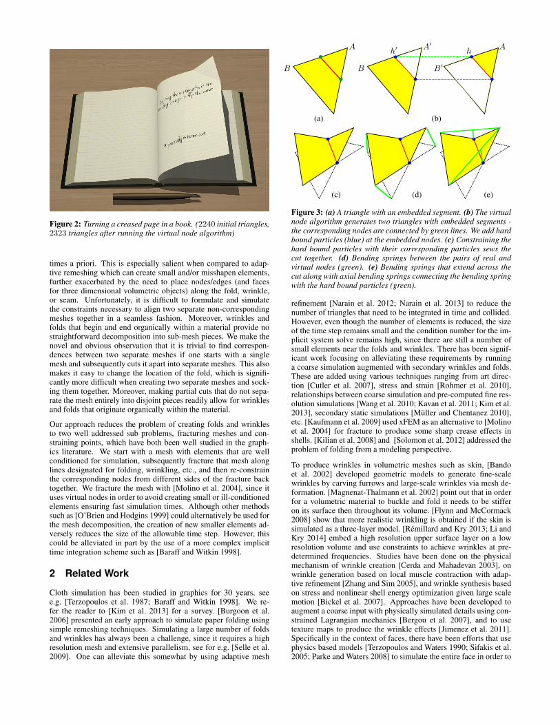
Figure 2: Turning a creased page in a book. (2240 initial triangles,2323 triangles after running the virtual node algorithm)
times a priori. This is especially salient when compared to adap-tive remeshing which can create small and/or misshapen elements,further exacerbated by the need to place nodes/edges (and facesfor three dimensional volumetric objects) along the fold, wrinkle,or seam. Unfortunately, it is difficult to formulate and simulatethe constraints necessary to align two separate non-correspondingmeshes together in a seamless fashion. Moreover, wrinkles andfolds that begin and end organically within a material provide nostraightforward decomposition into sub-mesh pieces. We make thenovel and obvious observation that it is trivial to find correspon-dences between two separate meshes if one starts with a singlemesh and subsequently cuts it apart into separate meshes. This alsomakes it easy to change the location of the fold, which is signifi-cantly more difficult when creating two separate meshes and sock-ing them together. Moreover, making partial cuts that do not sepa-rate the mesh entirely into disjoint pieces readily allow for wrinklesand folds that originate organically within the material.
Our approach reduces the problem of creating folds and wrinklesto two well addressed sub problems, fracturing meshes and con-straining points, which have both been well studied in the graph-ics literature. We start with a mesh with elements that are wellconditioned for simulation, subsequently fracture that mesh alonglines designated for folding, wrinkling, etc., and then re-constrainthe corresponding nodes from different sides of the fracture backtogether. We fracture the mesh with [Molino et al. 2004], since ituses virtual nodes in order to avoid creating small or ill-conditionedelements ensuring fast simulation times. Although other methodssuch as [O’Brien and Hodgins 1999] could alternatively be used forthe mesh decomposition, the creation of new smaller elements ad-versely reduces the size of the allowable time step. However, thiscould be alleviated in part by the use of a more complex implicittime integration scheme such as [Baraff and Witkin 1998].
2 Related Work
Cloth simulation has been studied in graphics for 30 years, seee.g. [Terzopoulos et al. 1987; Baraff and Witkin 1998]. We re-fer the reader to [Kim et al. 2013] for a survey. [Burgoon et al.2006] presented an early approach to simulate paper folding usingsimple remeshing techniques. Simulating a large number of foldsand wrinkles has always been a challenge, since it requires a highresolution mesh and extensive parallelism, see for e.g. [Selle et al.2009]. One can alleviate this somewhat by using adaptive mesh
(a) (b)
(c) (d) (e)
A
B
A′
B
h′A
B′
h
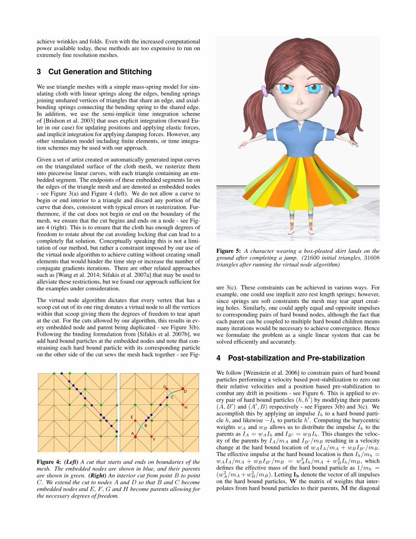
Figure 3: (a) A triangle with an embedded segment. (b) The virtualnode algorithm generates two triangles with embedded segments -the corresponding nodes are connected by green lines. We add hardbound particles (blue) at the embedded nodes. (c) Constraining thehard bound particles with their corresponding particles sews thecut together. (d) Bending springs between the pairs of real andvirtual nodes (green). (e) Bending springs that extend across thecut along with axial bending springs connecting the bending springwith the hard bound particles (green).
refinement [Narain et al. 2012; Narain et al. 2013] to reduce thenumber of triangles that need to be integrated in time and collided.However, even though the number of elements is reduced, the sizeof the time step remains small and the condition number for the im-plicit system solve remains high, since there are still a number ofsmall elements near the folds and wrinkles. There has been signif-icant work focusing on alleviating these requirements by runninga coarse simulation augmented with secondary wrinkles and folds.These are added using various techniques ranging from art direc-tion [Cutler et al. 2007], stress and strain [Rohmer et al. 2010],relationships between coarse simulation and pre-computed fine res-olution simulations [Wang et al. 2010; Kavan et al. 2011; Kim et al.2013], secondary static simulations [Muller and Chentanez 2010],etc. [Kaufmann et al. 2009] used xFEM as an alternative to [Molinoet al. 2004] for fracture to produce some sharp crease effects inshells. [Kilian et al. 2008] and [Solomon et al. 2012] addressed theproblem of folding from a modeling perspective.
To produce wrinkles in volumetric meshes such as skin, [Bandoet al. 2002] developed geometric models to generate fine-scalewrinkles by carving furrows and large-scale wrinkles via mesh de-formation. [Magnenat-Thalmann et al. 2002] point out that in orderfor a volumetric material to buckle and fold it needs to be stifferon its surface then throughout its volume. [Flynn and McCormack2008] show that more realistic wrinkling is obtained if the skin issimulated as a three-layer model. [Remillard and Kry 2013; Li andKry 2014] embed a high resolution upper surface layer on a lowresolution volume and use constraints to achieve wrinkles at pre-determined frequencies. Studies have been done on the physicalmechanism of wrinkle creation [Cerda and Mahadevan 2003], onwrinkle generation based on local muscle contraction with adap-tive refinement [Zhang and Sim 2005], and wrinkle synthesis basedon stress and nonlinear shell energy optimization given large scalemotion [Bickel et al. 2007]. Approaches have been developed toaugment a coarse input with physically simulated details using con-strained Lagrangian mechanics [Bergou et al. 2007], and to usetexture maps to produce the wrinkle effects [Jimenez et al. 2011].Specifically in the context of faces, there have been efforts that usephysics based models [Terzopoulos and Waters 1990; Sifakis et al.2005; Parke and Waters 2008] to simulate the entire face in order to
achieve wrinkles and folds. Even with the increased computationalpower available today, these methods are too expensive to run onextremely fine resolution meshes.
3 Cut Generation and Stitching
We use triangle meshes with a simple mass-spring model for sim-ulating cloth with linear springs along the edges, bending springsjoining unshared vertices of triangles that share an edge, and axial-bending springs connecting the bending spring to the shared edge.In addition, we use the semi-implicit time integration schemeof [Bridson et al. 2003] that uses explicit integration (forward Eu-ler in our case) for updating positions and applying elastic forces,and implicit integration for applying damping forces. However, anyother simulation model including finite elements, or time integra-tion schemes may be used with our approach.
Given a set of artist created or automatically generated input curveson the triangulated surface of the cloth mesh, we rasterize theminto piecewise linear curves, with each triangle containing an em-bedded segment. The endpoints of these embedded segments lie onthe edges of the triangle mesh and are denoted as embedded nodes- see Figure 3(a) and Figure 4 (left). We do not allow a curve tobegin or end interior to a triangle and discard any portion of thecurve that does, consistent with typical errors in rasterization. Fur-thermore, if the cut does not begin or end on the boundary of themesh, we ensure that the cut begins and ends on a node - see Fig-ure 4 (right). This is to ensure that the cloth has enough degrees offreedom to rotate about the cut avoiding locking that can lead to acompletely flat solution. Conceptually speaking this is not a limi-tation of our method, but rather a constraint imposed by our use ofthe virtual node algorithm to achieve cutting without creating smallelements that would hinder the time step or increase the number ofconjugate gradients iterations. There are other related approachessuch as [Wang et al. 2014; Sifakis et al. 2007a] that may be used toalleviate these restrictions, but we found our approach sufficient forthe examples under consideration.
The virtual node algorithm dictates that every vertex that has ascoop cut out of its one ring donates a virtual node to all the verticeswithin that scoop giving them the degrees of freedom to tear apartat the cut. For the cuts allowed by our algorithm, this results in ev-ery embedded node and parent being duplicated - see Figure 3(b).Following the binding formulation from [Sifakis et al. 2007b], weadd hard bound particles at the embedded nodes and note that con-straining each hard bound particle with its corresponding particleon the other side of the cut sews the mesh back together - see Fig-
A
B
C
D
F
E
H
G
Figure 4: (Left) A cut that starts and ends on boundaries of themesh. The embedded nodes are shown in blue, and their parentsare shown in green. (Right) An interior cut from point B to pointC. We extend the cut to nodes A and D so that B and C becomeembedded nodes and E, F , G and H become parents allowing forthe necessary degrees of freedom.
Figure 5: A character wearing a box-pleated skirt lands on theground after completing a jump. (21600 initial triangles, 31608triangles after running the virtual node algorithm)
ure 3(c). These constraints can be achieved in various ways. Forexample, one could use implicit zero rest length springs; however,since springs are soft constraints the mesh may tear apart creat-ing holes. Similarly, one could apply equal and opposite impulsesto corresponding pairs of hard bound nodes, although the fact thateach parent can be coupled to multiple hard bound children meansmany iterations would be necessary to achieve convergence. Hencewe formulate the problem as a single linear system that can besolved efficiently and accurately.
4 Post-stabilization and Pre-stabilization
We follow [Weinstein et al. 2006] to constrain pairs of hard boundparticles performing a velocity based post-stabilization to zero outtheir relative velocities and a position based pre-stabilization tocombat any drift in positions - see Figure 6. This is applied to ev-ery pair of hard bound particles (h, h′) by modifying their parents(A,B′) and (A′, B) respectively - see Figures 3(b) and 3(c). Weaccomplish this by applying an impulse Ih to a hard bound parti-cle h, and likewise −Ih to particle h′. Computing the barycentricweights wA and wB allows us to distribute the impulse Ih to theparents as IA = wAIh and IB′ = wBIh. This changes the veloc-ity of the parents by IA/mA and IB′/mB resulting in a velocitychange at the hard bound location of wAIA/mA + wBIB′/mB .The effective impulse at the hard bound location is then Ih/mh =wAIA/mA + wBIB′/mB = w2
AIh/mA + w2BIh/mB , which
defines the effective mass of the hard bound particle as 1/mh =(w2
A/mA +w2B/mB). Letting Ih denote the vector of all impulses
on the hard bound particles, W the matrix of weights that inter-polates from hard bound particles to their parents, M the diagonal

mass matrix of all parents, and ∆V the vector of velocity changesat all the hard bound particle locations, we have,
∆V = WTM−1WIh. (1)
This relation specifies the velocity changes at the hard bound parti-cles given impulses acting on the hard bound particles.
In order to match the velocity of a hard bound particle and its cor-responding particle we require Vh + ∆Vh = Vh′ + ∆Vh′ , or
∆Vh − ∆Vh′ = Vh′ − Vh. (2)
Writing Equation (2) for all such pairs of hard bound particles re-sults in,
WTnewM−1Wnew Ih = Vh′ − Vh (3)
The left hand side of Equation (3) is obtained as follows. Ih fromEquation (1) contains an entry Ih for a hard bound particle h andan equal and opposite entry −Ih for its corresponding hard boundparticle h′ for every pair (h, h′). Therefore we can coalesce Winto Wnew by subtracting a pair of columns for every pair (h, h′).In addition, we remove the −Ih entries from Ih to obtain Ih whichis half the size, and note that Wnew Ih = WIh. Thus M−1 doesnot need to change, and WT
new simply combines the change invelocities on the left hand side of Equation (1) to match the lefthand side of Equation (2).
Generally speaking, WTnewM−1Wnew is a symmetric positive
definite (SPD) matrix, which is constant throughout the simulationunless wrinkles are being dynamically added or removed. Theo-retically speaking, Ih has a length equal to the number of nodes ina cut making it one dimensional, and thus the coefficient matrix istwo dimensional or on the same order as the number of nodes in themesh. However, for coarse simulations with many wrinkles, such asthe pleats in Figure 1, a large number of segments may have embed-ded nodes on a scale approaching that of the number of segmentsin the mesh, potentially making the coefficient matrix effectivelythe size of the number of nodes squared. Thus, while it is temptingto precompute the inverse of the sparse coefficient matrix, the factthat its size can be large and that the inverse is dense makes ap-plying the inverse during simulation inefficient. On the other hand,
Figure 6: (Top left) A piece of cloth rendered with a Cartesiantexture map in order to visually highlight deformation and connec-tivity. (Top right) Using post-stabilization only, the cut can slowlydrift apart. (Bottom left) Pre-stabilization eliminates drift. (Bot-tom right) Bending springs can be used to make the cut seamless,if desired.
Figure 8: (Left) A piece of cloth with the cuts (green). Embeddednodes at the intersection of the cuts have four copies after cuttingthe cloth with the virtual node algorithm. (Right) The cloth bendssharply.
we can precompute the Cholesky factorization, which can be maderather sparse using permutation matrices which permute the orderof the unknowns [Hogben 2007]. Although a forward and back-ward substitution is required to invert the coefficient matrix usingthe precomputed Cholesky factorization, it can be (and is in oursimulations) significantly faster than precomputting the inverse.
The particle positions are updated using a forward Euler step:Xn+1 = Xn + ∆t(V + ∆V ) where ∆V is the change applied tokeep pairs of hard bound particles coincident in position. Althoughthe hard bound particles are not explicitly updated but rather inter-polated from their parents, we can still write the equations Xn+1
h =
Xnh + ∆t(Vh + ∆Vh) and Xn+1
h′ = Xnh′ + ∆t(Vh′ + ∆Vh′) sim-
ply by linearly interpolating the position updates of the two parentparticles using the barycentric weights. We desire Xn+1
h = Xn+1h′
and thus we have
∆Vh − ∆Vh′ = (Xnh′ −Xn
h )/∆t + Vh′ − Vh (4)
analogous to Equation (2). Thus we can solve
WTnewM−1Wnew Ih = (Xn
h′ − Xnh)/∆t + Vh′ − Vh (5)
in the same manner as Equation (3) in order to guarantee that thehard bound particles stay coincident in position.
If multiple cuts intersect at a point then the embedded node at theintersection can have multiple copies (up to 4 as allowed by thevirtual node algorithm) - see Figure 8. For a node with k copies, wewrite k− 1 equations - one equation paring each newly added copywith the original node.
5 Collisions and Self-Collisions
We follow the collision, contact, and friction formulation of [Brid-son et al. 2002] with the modifications made by [Selle et al. 2009]for parallelism, collisions, and accurate friction. For each hardbound particle location we create a new soft bound particle whichis connected to the hard bound location using the binding formu-lation of [Sifakis et al. 2007b]. We initialize the mass of the softbound particle to be identical to the effective mass of the hardbound particle and simulate the soft bound particle by inheritingforces from the hard bound particle. This allows the mass-springsystem to oscillate with its natural frequencies carrying soft boundparticles along for the ride as they track the hard bound particle lo-cations, without the soft bound particles adversely imparting extramass drag on the system. [Sifakis et al. 2007b] only mapped elasticforces to the soft bound particles ignoring the damping forces be-cause of a loss of symmetry during conjugate gradients. However,we note that this can be remedied similar to [Shinar et al. 2008], byusing the resulting velocities from the conjugate gradient solve inorder to recompute the damping forces explicitly. When calculat-ing the total momentum of the system, it is important to note thatthe soft bound particles do not contribute momentum based on theirvelocities, but rather based on the difference between their velocity

Figure 7: A paper plane collides with a wall and deforms near the tip. Notice how the plane maintains its structure even after the impact.(8000 initial triangles, 8716 triangles after running the virtual node algorithm)
and the velocity of the hard bound particle they are associated with.This way the system does not gain momentum as it accelerates thesoft bound particles to move with the hard bound particles, but onlyas the soft bound particles interact via collisions etc., changing theirrelative velocity with the hard bound particle. On the other hand,the virtual node’s momentum is directly included as part of the totalmomentum along with all regular cloth nodes.
We propose an impulse based fully momentum conserving alterna-tive to the binding springs proposed in [Sifakis et al. 2007b], formanaging the soft bound particles during collisions. First, softbound particles collide with rigid bodies and otherwise interactalong the lines of [Bridson et al. 2002] in a manner identical tothat of regular particles in the cloth mesh (unlike virtual particleswhich do not for example collide). Then, in order to keep the softbound particles from drifting too far from their hard bound targetlocations, we apply equal and opposite impulses to the soft boundparticles and their hard bound target locations, ±Is. Applying im-pulse Is to the hard bound particles results in a change in velocityof WTM−1WIs, while applying −Is to the soft bound particlesresults in a change in velocity of −M−1
s Is where Ms is a diagonalmatrix of soft bound particle masses. Thus the analog of Equation(3) is,
(WTM−1W + M−1s )Is = Vs − Vh. (6)
where WTM−1W + M−1s is SPD and can be solved along the
lines of Equation (3). In order to synchronize positions we solvethe following system similar to Equation (5),
(WTM−1W + M−1s )Is = (Xn
s − Xnh)/∆t + Vs − Vh. (7)
Note that every time a segment of a mesh is cut we create two em-bedded nodes, which are each assigned a hard bound particle loca-tion as well as a soft bound particle. We have found that applyingimpulses between all corresponding pairs of soft bound particles inorder to sync their velocities (positions) first, before syncing themwith the hard bound particles along the lines of Equation (6) (Equa-tion (7)) provides for better results.
For self collisions we follow [Bridson et al. 2002] by generating anauxiliary mesh which will maintain a collision free state. This meshconsists of all the non-virtual particles in the original mesh alongwith one new particle for each pair of embedded nodes. The re-sulting mesh is connected in the same fashion as the original meshbut modified to include the embedded nodes and segments in theobvious way. Furthermore, all the quads are subdivided into trian-gles. When the simulation starts, this collision mesh is coincidentwith the simulation mesh and is collision free. At some later pointin time a new collision free state is constructed as follows. Thecurrent simulated positions of the particles on the collision meshare denoted as the proposed state. Then we assume linear trajec-tories between the last collision free state and the proposed state.
Collisions and repulsions are then applied along the lines of [Brid-son et al. 2002] in order to compute a new collision free state thecollision mesh may evolve to. These positions are recorded as thenew collision free state. The new velocity is determined by takingthe velocity at the proposed state and adding in all the momentumchanges resulting from the processing of collisions and repulsionsusing the method of [Bridson et al. 2002]. For nodes in the regu-lar mesh we can simply add the change in momentum to that node.For nodes that correspond to the hard bound particle locations thechange in momentum is distributed equally to all their correspond-ing soft bound particles. At this point, one could attempt to movethe virtual nodes to a better location so that the hard bound particlesare better synced with their corresponding positions in the collisionfree state. However, this is not necessary because the linear trajec-tories between the last collision free state and the current mesh willaim to match whatever positions the hard bound particles happen tobe in, allowing (at least) for one-way syncing. On the other handit might improve the behaviour of the simulation and/or allow forlarger time steps.
6 Controlling bending
As shown in Figure 3 the distance between parent nodes and thecorresponding virtual nodes increases/decreases as the rotation an-gle increases/decreases (i.e. A and A′, B and B′). Therefore, wecan add springs that connect a node with its corresponding virtualnode in order to resist bending - see Figure 3(d). We use implicit
(a) (b) (c) (d)
Figure 9: (a) A piece of cloth hanging from its opposite corners.(b) Locally remeshing the cloth so that it has degrees of freedomon a line along the diagonal results in more bending, but makes thesimulation 10× slower (the smaller elements require a more strin-gent time step restriction). (c) Our sharp-crease bending elementscan be applied with almost no additional simulation cost. (d) Fur-thermore, bending springs can be utilized to achieve results similarto remeshing, but 10× faster.
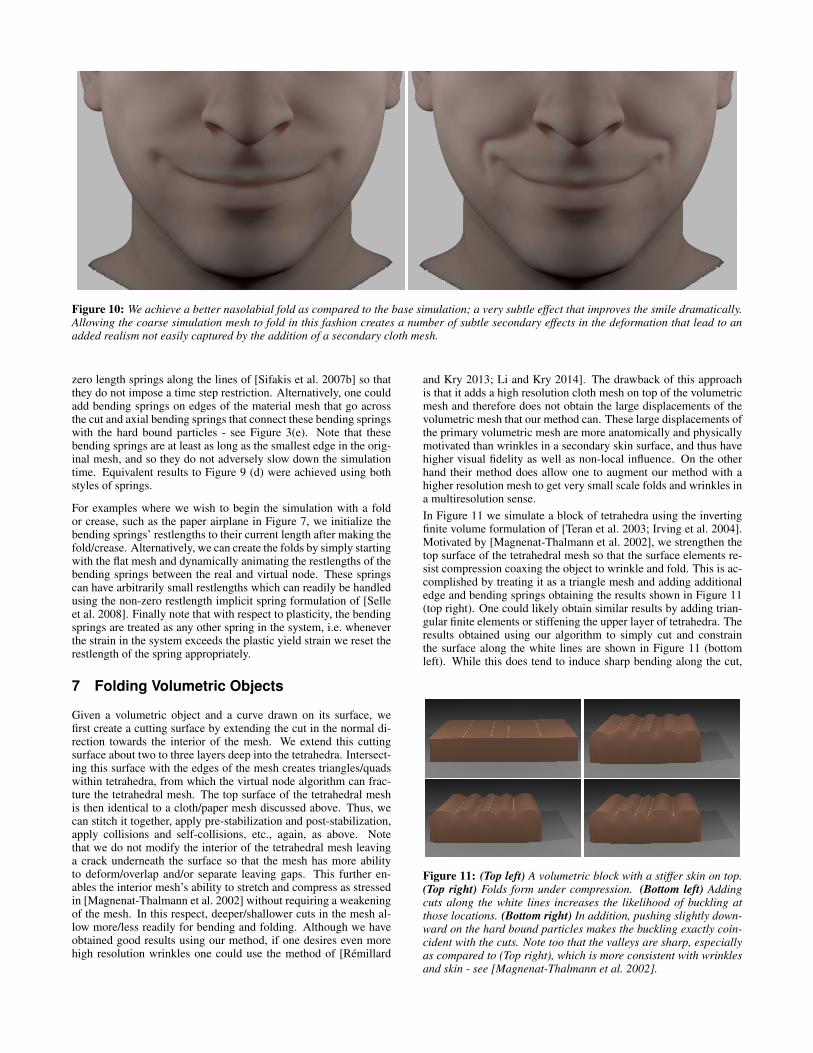
Figure 10: We achieve a better nasolabial fold as compared to the base simulation; a very subtle effect that improves the smile dramatically.Allowing the coarse simulation mesh to fold in this fashion creates a number of subtle secondary effects in the deformation that lead to anadded realism not easily captured by the addition of a secondary cloth mesh.
zero length springs along the lines of [Sifakis et al. 2007b] so thatthey do not impose a time step restriction. Alternatively, one couldadd bending springs on edges of the material mesh that go acrossthe cut and axial bending springs that connect these bending springswith the hard bound particles - see Figure 3(e). Note that thesebending springs are at least as long as the smallest edge in the orig-inal mesh, and so they do not adversely slow down the simulationtime. Equivalent results to Figure 9 (d) were achieved using bothstyles of springs.
For examples where we wish to begin the simulation with a foldor crease, such as the paper airplane in Figure 7, we initialize thebending springs’ restlengths to their current length after making thefold/crease. Alternatively, we can create the folds by simply startingwith the flat mesh and dynamically animating the restlengths of thebending springs between the real and virtual node. These springscan have arbitrarily small restlengths which can readily be handledusing the non-zero restlength implicit spring formulation of [Selleet al. 2008]. Finally note that with respect to plasticity, the bendingsprings are treated as any other spring in the system, i.e. wheneverthe strain in the system exceeds the plastic yield strain we reset therestlength of the spring appropriately.
7 Folding Volumetric Objects
Given a volumetric object and a curve drawn on its surface, wefirst create a cutting surface by extending the cut in the normal di-rection towards the interior of the mesh. We extend this cuttingsurface about two to three layers deep into the tetrahedra. Intersect-ing this surface with the edges of the mesh creates triangles/quadswithin tetrahedra, from which the virtual node algorithm can frac-ture the tetrahedral mesh. The top surface of the tetrahedral meshis then identical to a cloth/paper mesh discussed above. Thus, wecan stitch it together, apply pre-stabilization and post-stabilization,apply collisions and self-collisions, etc., again, as above. Notethat we do not modify the interior of the tetrahedral mesh leavinga crack underneath the surface so that the mesh has more abilityto deform/overlap and/or separate leaving gaps. This further en-ables the interior mesh’s ability to stretch and compress as stressedin [Magnenat-Thalmann et al. 2002] without requiring a weakeningof the mesh. In this respect, deeper/shallower cuts in the mesh al-low more/less readily for bending and folding. Although we haveobtained good results using our method, if one desires even morehigh resolution wrinkles one could use the method of [Remillard
and Kry 2013; Li and Kry 2014]. The drawback of this approachis that it adds a high resolution cloth mesh on top of the volumetricmesh and therefore does not obtain the large displacements of thevolumetric mesh that our method can. These large displacements ofthe primary volumetric mesh are more anatomically and physicallymotivated than wrinkles in a secondary skin surface, and thus havehigher visual fidelity as well as non-local influence. On the otherhand their method does allow one to augment our method with ahigher resolution mesh to get very small scale folds and wrinkles ina multiresolution sense.In Figure 11 we simulate a block of tetrahedra using the invertingfinite volume formulation of [Teran et al. 2003; Irving et al. 2004].Motivated by [Magnenat-Thalmann et al. 2002], we strengthen thetop surface of the tetrahedral mesh so that the surface elements re-sist compression coaxing the object to wrinkle and fold. This is ac-complished by treating it as a triangle mesh and adding additionaledge and bending springs obtaining the results shown in Figure 11(top right). One could likely obtain similar results by adding trian-gular finite elements or stiffening the upper layer of tetrahedra. Theresults obtained using our algorithm to simply cut and constrainthe surface along the white lines are shown in Figure 11 (bottomleft). While this does tend to induce sharp bending along the cut,
Figure 11: (Top left) A volumetric block with a stiffer skin on top.(Top right) Folds form under compression. (Bottom left) Addingcuts along the white lines increases the likelihood of buckling atthose locations. (Bottom right) In addition, pushing slightly down-ward on the hard bound particles makes the buckling exactly coin-cident with the cuts. Note too that the valleys are sharp, especiallyas compared to (Top right), which is more consistent with wrinklesand skin - see [Magnenat-Thalmann et al. 2002].
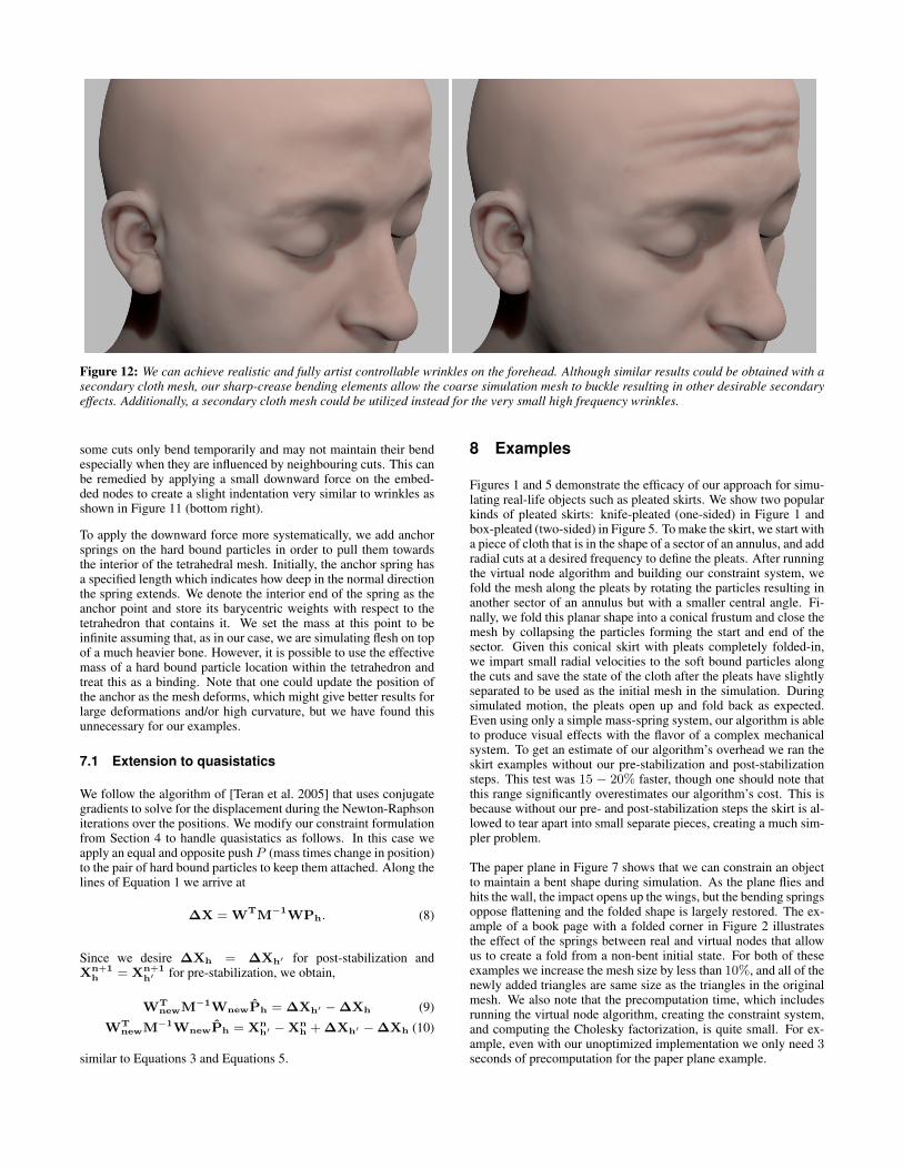
Figure 12: We can achieve realistic and fully artist controllable wrinkles on the forehead. Although similar results could be obtained with asecondary cloth mesh, our sharp-crease bending elements allow the coarse simulation mesh to buckle resulting in other desirable secondaryeffects. Additionally, a secondary cloth mesh could be utilized instead for the very small high frequency wrinkles.
some cuts only bend temporarily and may not maintain their bendespecially when they are influenced by neighbouring cuts. This canbe remedied by applying a small downward force on the embed-ded nodes to create a slight indentation very similar to wrinkles asshown in Figure 11 (bottom right).
To apply the downward force more systematically, we add anchorsprings on the hard bound particles in order to pull them towardsthe interior of the tetrahedral mesh. Initially, the anchor spring hasa specified length which indicates how deep in the normal directionthe spring extends. We denote the interior end of the spring as theanchor point and store its barycentric weights with respect to thetetrahedron that contains it. We set the mass at this point to beinfinite assuming that, as in our case, we are simulating flesh on topof a much heavier bone. However, it is possible to use the effectivemass of a hard bound particle location within the tetrahedron andtreat this as a binding. Note that one could update the position ofthe anchor as the mesh deforms, which might give better results forlarge deformations and/or high curvature, but we have found thisunnecessary for our examples.
7.1 Extension to quasistatics
We follow the algorithm of [Teran et al. 2005] that uses conjugategradients to solve for the displacement during the Newton-Raphsoniterations over the positions. We modify our constraint formulationfrom Section 4 to handle quasistatics as follows. In this case weapply an equal and opposite push P (mass times change in position)to the pair of hard bound particles to keep them attached. Along thelines of Equation 1 we arrive at
∆X = WTM−1WPh. (8)
Since we desire ∆Xh = ∆Xh′ for post-stabilization andXn+1
h = Xn+1h′ for pre-stabilization, we obtain,
WTnewM−1WnewPh = ∆Xh′ − ∆Xh (9)
WTnewM−1WnewPh = Xn
h′ − Xnh + ∆Xh′ − ∆Xh (10)
similar to Equations 3 and Equations 5.
8 Examples
Figures 1 and 5 demonstrate the efficacy of our approach for simu-lating real-life objects such as pleated skirts. We show two popularkinds of pleated skirts: knife-pleated (one-sided) in Figure 1 andbox-pleated (two-sided) in Figure 5. To make the skirt, we start witha piece of cloth that is in the shape of a sector of an annulus, and addradial cuts at a desired frequency to define the pleats. After runningthe virtual node algorithm and building our constraint system, wefold the mesh along the pleats by rotating the particles resulting inanother sector of an annulus but with a smaller central angle. Fi-nally, we fold this planar shape into a conical frustum and close themesh by collapsing the particles forming the start and end of thesector. Given this conical skirt with pleats completely folded-in,we impart small radial velocities to the soft bound particles alongthe cuts and save the state of the cloth after the pleats have slightlyseparated to be used as the initial mesh in the simulation. Duringsimulated motion, the pleats open up and fold back as expected.Even using only a simple mass-spring system, our algorithm is ableto produce visual effects with the flavor of a complex mechanicalsystem. To get an estimate of our algorithm’s overhead we ran theskirt examples without our pre-stabilization and post-stabilizationsteps. This test was 15 − 20% faster, though one should note thatthis range significantly overestimates our algorithm’s cost. This isbecause without our pre- and post-stabilization steps the skirt is al-lowed to tear apart into small separate pieces, creating a much sim-pler problem.
The paper plane in Figure 7 shows that we can constrain an objectto maintain a bent shape during simulation. As the plane flies andhits the wall, the impact opens up the wings, but the bending springsoppose flattening and the folded shape is largely restored. The ex-ample of a book page with a folded corner in Figure 2 illustratesthe effect of the springs between real and virtual nodes that allowus to create a fold from a non-bent initial state. For both of theseexamples we increase the mesh size by less than 10%, and all of thenewly added triangles are same size as the triangles in the originalmesh. We also note that the precomputation time, which includesrunning the virtual node algorithm, creating the constraint system,and computing the Cholesky factorization, is quite small. For ex-ample, even with our unoptimized implementation we only need 3seconds of precomputation for the paper plane example.

Figures 10 and 12 demonstrate the effectiveness of our method ingenerating facial wrinkles. For both of the examples, we drew fairlycoarse curves, each containing approximately 4-6 linear segments,but still obtain convincing results. We vary the restlength of the an-chor springs to fade in the wrinkles as the person smiles (flexing thezygomaticus muscle) or lifts their eyebrows (flexing the frontalismuscle). The restlengths are not only set as a function of muscleactivations, but also based on their distance from the ends of thecurve to enhance the organic nature of the fading in/out effect onthe open boundaries of the wrinkle lines. The face model has 2.5million tetrahedra and 35 muscles. Adding the smile lines and theforehead wrinkles increases the simulation time by 20% due to thefact that the more complex problem requires more conjugate gradi-ent iterations to converge.
We render the collision mesh in all our examples since it alwaysmaintains a collision free state. Since the newly added vertices inthe collision mesh (i.e. embedded nodes) lie on mesh edges withknown interpolation weights, quantities such as texture coordinatescan be easily recomputed via an interpolation from the initial mesh.
9 Conclusions, Limitations, and Future Work
We have presented a robust, art-directable, and efficient approachfor generating sharp folds and wrinkles on surfaces and volumet-ric objects and demonstrated its potential impact through a varietyof examples. A significant benefit of our approach is the computa-tional savings in run time. Although our algorithm requires slightlymore pre-computation in the initialization stage in order to set upthe constraint system, the per frame simulation times are almostidentical to standard simulations. Mesh refinement, on the otherhand, typically significantly increases the computational effort re-quired even when carried out adaptively.
Since the virtual node algorithm limits us to one cut per edge, wecannot make wrinkles with a frequency higher than the resolution ofthe mesh without some adaptive mesh refinement. In addition, thevirtual node algorithm does not allow cuts to pass through verticesso our embedded nodes generally cannot be coinciding with meshvertices (except at the endpoints). In practice, this is typically notan issue since the weights can be very small placing the embeddednode almost arbitrarily close to a vertex. These restrictions can bealleviated with approaches such as [Sifakis et al. 2007a; Wang et al.2014]. This makes our approach better than global remeshing al-gorithms since we will never add smaller triangles even in presenceof cuts that are very close, whereas any global remeshing algorithmwill require to have smaller triangles in this region when it tries toalign the mesh with all the cuts.
Our method is a straightforward albeit useful combination of thevirtual node algorithm and constraint stabilization. Our examplesmodel non-dynamic creases. However, since the virtual node algo-rithm can be used to cut a mesh dynamically as shown in [Molinoet al. 2004] and our constraint matrix can be trivially recomputedbased on the new cut mesh, the extension of our method to dynam-ically added creases should be straightforward. The cost of dynam-ically adding a crease would be the cost of running the virtual nodealgorithm (or any other cutting algorithm) on the crease along withthe cost of recomputing the W matrix, and both of these steps arequite efficient.
Acknowledgements
Research was supported in part by ONR N00014-13-1-0346, ONRN00014-11-1-0707, ARL AHPCRC W911NF-07-0027, and the In-tel Science and Technology Center for Visual Computing. Comput-ing resources were provided in part by ONR N00014-05-1-0479.
S.P. was supported by the Stanford Graduate Fellowship.
References
BANDO, Y., KURATATE, T., AND NISHITA, T. 2002. A simplemethod for modeling wrinkles on human skin. In Proc. of the10th Pacific Conf. on Comput. Graph. and Applications.
BARAFF, D., AND WITKIN, A. 1998. Large steps in cloth simula-tion. In ACM SIGGRAPH 98, ACM Press/ACM SIGGRAPH.
BERGOU, M., MATHUR, S., WARDETZKY, M., AND GRINSPUN,E. 2007. Tracks: Toward directable thin shells. In ACM SIG-GRAPH 2007 Papers, SIGGRAPH ’07.
BICKEL, B., BOTSCH, M., ANGST, R., MATUSIK, W., OTADUY,M., PFISTER, H., AND GROSS, M. 2007. Multi-scale captureof facial geometry and motion. SIGGRAPH ’07.
BRIDSON, R., FEDKIW, R., AND ANDERSON, J. 2002. Robusttreatment of collisions, contact and friction for cloth animation.ACM Trans. Graph. 21, 3, 594–603.
BRIDSON, R., MARINO, S., AND FEDKIW, R. 2003. Simulationof clothing with folds and wrinkles. In Proc. of the 2003 ACMSIGGRAPH/Eurographics Symp. on Comput. Anim., 28–36.
BURGOON, R., WOOD, Z. J., AND GRINSPUN, E. 2006. Discreteshells origami. In 21st International Conference on Computersand Their Applications, CATA-2006, Seattle, Washington, USA,March 23-25, 2006, Proceedings.
CERDA, E., AND MAHADEVAN, L. 2003. Geometry and physicsof wrinkling. Phys. Rev. Lett. 90 (Feb).
CUTLER, L. D., GERSHBEIN, R., WANG, X. C., CURTIS, C.,MAIGRET, E., PRASSO, L., AND FARSON, P. 2007. Anart-directed wrinkle system for cg character clothing and skin.Graph. Models 69.
FLYNN, C., AND MCCORMACK, B. A. O. 2008. Finite elementmodelling of forearm skin wrinkling. Skin Research and Tech..
GOULEKAS, K. E. 2001. Visual Effects in a Digital World: A Com-prehensive Glossary of over 7,000 Visual Effects Terms, 1st ed.Morgan Kaufmann Publishers Inc.
HOGBEN, L., Ed. 2007. Handbook of Linear Algebra, 1st ed.Chapman and Hall/CRC Press, Boca Raton.
IRVING, G., TERAN, J., AND FEDKIW, R. 2004. Invertible finiteelements for robust simulation of large deformation. In Proc. ofthe ACM SIGGRAPH/Eurographics Symp. on Comput. Anim.
JIMENEZ, J., ECHEVARRIA, J. I., OAT, C., AND GUTIERREZ, D.2011. GPU Pro 2. AK Peters Ltd., ch. Practical and RealisticFacial Wrinkles Animation.
KAUFMANN, P., MARTIN, S., BOTSCH, M., GRINSPUN, E., ANDGROSS, M. 2009. Enrichment textures for detailed cutting ofshells. ACM Trans. Graph..
KAVAN, L., GERSZEWSKI, D., BARGTEIL, A., AND SLOAN, P.-P. 2011. Physics-inspired upsampling for cloth simulation ingames. ACM Trans. Graph. 30.
KILIAN, M., FLORY, S., CHEN, Z., MITRA, N. J., SHEFFER,A., AND POTTMANN, H. 2008. Curved folding. ACM Trans.Graph..
KIM, D., KOH, W., NARAIN, R., FATAHALIAN, K., TREUILLE,A., AND O’BRIEN, J. F. 2013. Near-exhaustive precomputationof secondary cloth effects. ACM Trans. Graph. 32, 87:1–87:8.
LI, P., AND KRY, P. G. 2014. Multi-layer skin simulation withadaptive constraints. In Proceedings of the Seventh InternationalConference on Motion in Games, 171–176.
MAGNENAT-THALMANN, N., KALRA, P., LUC LEVEQUE, J.,BAZIN, R., BATISSE, D., AND QUERLEUX, B. 2002. A com-putational skin model: Fold and wrinkle formation. Trans. Info.Tech. Biomed. 6.
MOLINO, N., BAO, Z., AND FEDKIW, R. 2004. A virtual nodealgorithm for changing mesh topology during simulation. ACMTrans. Graph. (SIGGRAPH Proc.) 23, 385–392.
MULLER, M., AND CHENTANEZ, N. 2010. Wrinkle meshes. InProceedings of the 2010 ACM SIGGRAPH/Eurographics Sym-posium on Computer Animation, SCA ’10.
NARAIN, R., SAMII, A., AND O’BRIEN, J. F. 2012. Adaptiveanisotropic remeshing for cloth simulation. ACM Transactionson Graphics, 147:1–10.
NARAIN, R., PFAFF, T., AND O’BRIEN, J. F. 2013. Folding andcrumpling adaptive sheets. ACM Trans. Graph. 32, 4, 51:1–51:8.
O’BRIEN, J., AND HODGINS, J. 1999. Graphical modeling andanimation of brittle fracture. In Proc. SIGGRAPH 99, vol. 18.
PARKE, F. I., AND WATERS, K. 2008. Computer Facial Anima-tion, second edition. AK Peters, Ltd.
REMILLARD, O., AND KRY, P. G. 2013. Embedded thin shells forwrinkle simulation. ACM Trans. Graph. 32, 4, 50:1–50:8.
ROHMER, D., POPA, T., CANI, M.-P., HAHMANN, S., ANDSHEFFER, A. 2010. Animation wrinkling: Augmenting coarsecloth simulations with realistic-looking wrinkles. SIGGRAPHASIA ’10.
SELLE, A., LENTINE, M., AND FEDKIW, R. 2008. A mass springmodel for hair simulation. ACM Transactions on Graphics.
SELLE, A., SU, J., IRVING, G., AND FEDKIW, R. 2009. Robusthigh-resolution cloth using parallelism, history-based collisions,and accurate friction. IEEE Trans. on Vis. and Comput. Graph..
SHINAR, T., SCHROEDER, C., AND FEDKIW, R. 2008. Two-waycoupling of rigid and deformable bodies. SCA ’08, 95–103.
SIFAKIS, E., NEVEROV, I., AND FEDKIW, R. 2005. Automaticdetermination of facial muscle activations from sparse motioncapture marker data. ACM Trans. Graph. (SIGGRAPH Proc.).
SIFAKIS, E., DER, K., AND FEDKIW, R. 2007. Arbitrary cuttingof deformable tetrahedralized objects. In Proc. of ACM SIG-GRAPH/Eurographics Symp. on Comput. Anim.
SIFAKIS, E., SHINAR, T., IRVING, G., AND FEDKIW, R. 2007.Hybrid simulation of deformable solids. In Proc. of ACM SIG-GRAPH/Eurographics Symp. on Comput. Anim., 81–90.
SOLOMON, J., VOUGA, E., WARDETZKY, M., AND GRINSPUN,E. 2012. Flexible developable surfaces. Comp. Graph. Forum.
TERAN, J., BLEMKER, S., NG, V., AND FEDKIW, R. 2003. Finitevolume methods for the simulation of skeletal muscle. In Proc. of2003 ACM SIGGRAPH/Eurographics Symp. on Comput. Anim.
TERAN, J., SIFAKIS, E., IRVING, G., AND FEDKIW, R. 2005.Robust quasistatic finite elements and flesh simulation. Proc. of2005 ACM SIGGRAPH/Eurographics Symp. on Comput. Anim..
TERZOPOULOS, D., AND WATERS, K. 1990. Physically-basedfacial modeling, analysis, and animation. J. Vis. and Comput.Anim. 1 (december), 73–80.
TERZOPOULOS, D., PLATT, J., BARR, A., AND FLEISCHER, K.1987. Elastically deformable models. Proc. SIGGRAPH 87.
WANG, H., HECHT, F., RAMAMOORTHI, R., AND O’BRIEN, J. F.2010. Example-based wrinkle synthesis for clothing animation.In ACM SIGGRAPH 2010 Papers, SIGGRAPH ’10.
WANG, Y., JIANG, C., SCHROEDER, C., AND TERAN, J. 2014.An Adaptive Virtual Node Algorithm with Robust Mesh Cutting.In Eurographics/ACM SIGGRAPH Symp. on Comp. Anim.
WEINSTEIN, R., TERAN, J., AND FEDKIW, R. 2006. Dynamicsimulation of articulated rigid bodies with contact and collision.IEEE TVCG 12, 3, 365–374.
ZHANG, Y., AND SIM, T. 2005. Realistic and efficient wrinklesimulation using an anatomy-based face model with adaptive re-finement. In Proc. of the Comp. Graph. International 2005.


![FOLDING FLAT CREASE PATTERNS WITH THICK MATERIALSjasonku/pdf/THICKFOLDING_ASME.pdf · 2015-04-21 · plications from kinetic architecture [1] and solar panel deploy-ment [2], to robotics](https://img.dokumen.tips/doc/110x75/5eb9f416974f3f421c518a6d/folding-flat-crease-patterns-with-thick-materials-jasonkupdfthickfoldingasmepdf.jpg)