Embed Size (px)
Citation preview

This content has been downloaded from IOPscience. Please scroll down to see the full text.
Download details:
IP Address: 131.104.62.10
This content was downloaded on 27/09/2014 at 16:51
Please note that terms and conditions apply.
A new sacrificial layer process for the fabrication of micromechanical systems
View the table of contents for this issue, or go to the journal homepage for more
1997 J. Micromech. Microeng. 7 128
(http://iopscience.iop.org/0960-1317/7/3/012)
Home Search Collections Journals About Contact us My IOPscience
J. Micromech. Microeng. 7 (1997) 128–130. Printed in the UK PII: S0960-1317(97)83175-0
A new sacrificial layer process for thefabrication of micromechanicalsystems
Zheng Cui † and Ron A Lawes
Central Microstructure Facility, Rutherford Appleton Laboratory, Chilton, Didcot,Oxon OX11 0QX, UK
Presented on 21 October 1996, accepted for publication on 8 April 1997
Abstract. A new process using photoresists as sacrificial layers has beendeveloped to fabricate micromechanical components and systems. Commonlyused photoresists are spun on a substrate as a sacrificial layer and patterned by amask aligner. Free-standing metal structures are built by patterning a second layerof thick photoresist and electroplating on top of the photoresist sacrificial layer.Electrostatic microactuators and micromotors have been fabricated using the newphotoresist sacrificial layer technique. Compared with all the existing sacrificiallayer techniques, the photoresists used in the new process are easy to coat, easyto dissolve and less process steps are involved. The process is compatible withmost of the materials and processes used in existing microfabrication technology.The fabrication of micromechanical systems becomes much simpler and cheaperwith the use of a photoresist as a sacrificial layer.
1. Introduction
Most micromechanical systems require free-standingstructures so that mechanical movement can be achieved.The use of a sacrificial layer is the key technique torelease a micromechanical component on a substrate. Inthe development of LIGA and LIGA-like processes [1],different types of metallic sacrificial layers have been used,such as titanium, aluminium, copper and chromium [2–4].There have also been reports on the use of phosphoric glassor silicon dioxide as sacrificial layers [5, 6].
There are several drawbacks regarding existingsacrificial layer materials. Firstly, coating of the materialsis costly and time consuming. Coating by thermalevaporation does not give good quality films of severalmicrometres thickness. Coating by plasma sputtering needsexpensive equipment and the coating rate is only around50 nm per minute for most of the metals. Secondly, itis difficult to dissolve the sacrificial materials. Strongacids are normally used, which creates the problem ofmaterial compatibility. The acid used must not attackthe materials used for micromechanical components orsubstrate. Thirdly, these materials cannot be patterneddirectly—an additional photolithography step is needed.In this paper, a new low-cost process using photoresistsas sacrificial layers has been developed. Electrostaticmicroactuators and micromotors have been fabricated usingthe new sacrificial layer technique. The photoresistsacrificial layer is easy to coat, easy to dissolve, can be
† E-mail address: [email protected]
patterned directly and is compatible with the materials andprocesses used in conventional IC manufacturing.
2. New sacrificial layer process
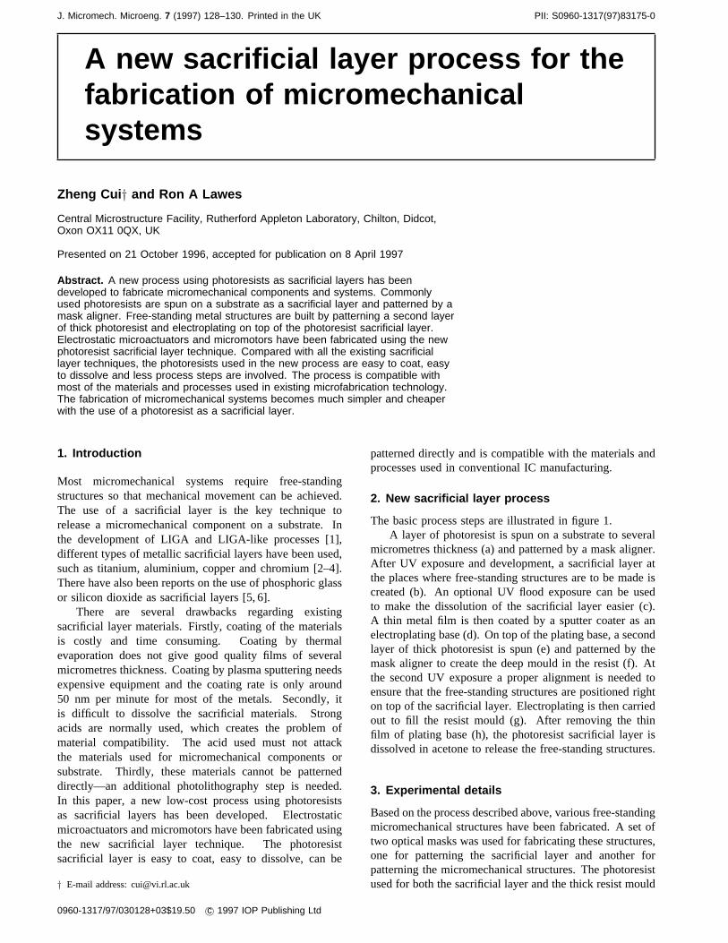
The basic process steps are illustrated in figure 1.A layer of photoresist is spun on a substrate to several
micrometres thickness (a) and patterned by a mask aligner.After UV exposure and development, a sacrificial layer atthe places where free-standing structures are to be made iscreated (b). An optional UV flood exposure can be usedto make the dissolution of the sacrificial layer easier (c).A thin metal film is then coated by a sputter coater as anelectroplating base (d). On top of the plating base, a secondlayer of thick photoresist is spun (e) and patterned by themask aligner to create the deep mould in the resist (f). Atthe second UV exposure a proper alignment is needed toensure that the free-standing structures are positioned righton top of the sacrificial layer. Electroplating is then carriedout to fill the resist mould (g). After removing the thinfilm of plating base (h), the photoresist sacrificial layer isdissolved in acetone to release the free-standing structures.
3. Experimental details
Based on the process described above, various free-standingmicromechanical structures have been fabricated. A set oftwo optical masks was used for fabricating these structures,one for patterning the sacrificial layer and another forpatterning the micromechanical structures. The photoresistused for both the sacrificial layer and the thick resist mould
0960-1317/97/030128+03$19.50 c© 1997 IOP Publishing Ltd

New sacrificial layer process
Figure 1. Photoresist sacrificial layer process.
Figure 2. Image of photoresist mould before electroplatingwith metal, with visible underlying photoresist sacrificiallayer.
is AZ4562. The sacrificial layer resist was spun up to4 µm thickness on a glass substrate and baked at 90◦Cfor 30 min. It was then exposed with a mask aligner for20 s and developed in AZ400K for 3 min. A 100 nmthick of copper film was deposited on top of the sacrificiallayer as the plating base by a plasma sputter coater. Asecond layer of AZ4562 (thickness 16µm) was spun onthe copper plating base and baked at 90◦C for 30 min.The exposure time and development time for the second
Figure 3. Free-standing metal structure after thephotoresist sacrificial layer has been dissolved.
(a)
(b)
Figure 4. (a) Photoresist mould for a micromotor withvisible photoresist sacrificial layer underneath the rotor. (b)A micromotor after electroplating and dissolving thephotoresist sacrificial layer.
129

Zheng Cui and R A Lawes
photoresist layer must be carefully controlled to achievea resist mould with vertical sidewalls. Figure 2 showsthe photoresist patterns after exposure of the resist mouldand before metal electroplating. The underlying photoresistsacrificial layer is visible. After electroplating of nickel, thephotoresist mould was dissolved in acetone and the copperplating base was etched away by a quick dip in acid.
The photoresist sacrificial layer can normally bedissolved in acetone, which may need a few hours to cleanall the underlying photoresists depending on the coverage offree-standing metal structures. Alternatively, an UV floodexposure can be performed on the photoresist sacrificiallayer after the patterning and before the coating of thinmetal layer, as shown in figure 1(c). As the photoresistsacrificial layer has been exposed, it can be dissolvedin developer instead of acetone to release free-standingstructures. It was found that the UV flood exposure helpsto dissolve the sacrificial layer much more quickly thanis possible with the acetone process. Figure 3 shows afree-standing metal structure after the photoresist sacrificiallayer has been dissolved.
Because the photoresist sacrificial layer can be directlypatterned with a mask aligner with high precision, theselective release of micromechanical components withcomplicated free-standing structures can be easily achieved.Figure 4(a) shows part of a resist mould of an electrostaticmicromotor before electroplating with metal. The rotor sitson a doughnut-shaped photoresist sacrificial layer which isvisible from the photograph, with the central shaft and thestators anchored to the substrate. After electroplating anddissolving the sacrificial layer, the rotor is fully released,as shown in figure 4(b).
4. Summary
A new process using a photoresist as a sacrificial layerhas been developed. Various micromechanical componentshave been fabricated by the new process. The photoresistsacrificial layer is easy to coat, easy to dissolve, canbe patterned directly and is compatible with materialsand processes in conventional IC manufacturing andmicrosystems technology. Combined with optical contactprinting and electroplating, the process offers a low-cost and fast turnaround development for micromechanicalsystems, and is accessible to e.g. universities and smallcompanies with a minimal requirement for new fabricationequipment.
References
[1] Lochel B, Maciossek A, Knig M, Quenzer H J and HuberH-L 1994 Galvanoplated 3D structures for micro systemsMicroelectron. Eng.23 455
[2] Burbaum C, Mohr J and Bley P 1991 Fabrication ofcapacitive acceleration sensors by the LIGA techniqueSens. ActuatorsA 25–7613
[3] Frazier A B, Ahn C H and Allen M G 1994 Development ofmicromachined devices using polymide-based processesSens. ActuatorsA 45 47
[4] Maciossek A, Lochel B, Quenzer H, Wagner B, Shulze Sand Noetzel J 1995 Galvanoplating and sacrificial layersfor surface micromachiningMicroelectron. Eng.27 503
[5] Howe R 1988 Surface micromachining for microsensors andmicroactuatorsJ. Vac. Sci. Technol.B 6 (6) 1809
[6] Mehregany M, Gabriel K and Trimmer W 1988 Integratedfabrication of polysilicon mechanismsIEEE Trans.Electron Dev.V 35 (6) 719
130