Embed Size (px)
Citation preview

(A New Proposal to Jefferson Lab PAC34)Measurement of the Neutron Electromagnetic Form Factor
Ratio GnE/Gn
M at High Q2
A. Camsonne, E. Chudakov, P. Degtyarenko, J. Gomez,O. Hansen, D. W. Higinbotham, C. W. de Jager, M. Jones, J. LeRose, R. Michaels, S. Nanda,
A. Saha, V. Sulkosky, B. Wojtsekhowski (spokesperson and contact person), S. WoodThomas Jefferson National Accelerator Facility, Newport News, VA 23606
H. Baghdasaryan, G. Cates (spokesperson), D. Day, N. Kalantarians,R. Lindgren, N. Liyanage, V. Nelyubin†, B. E. Norum,
S. Riordan (spokesperson), M. Shabestari, W. A. Tobias, K. WangUniversity of Virginia, Charlottesville, VA 22901
D. Nikolenko, I. Rachek, Yu. ShestakovBudker Institute, Novosibirsk, Russia
K. Aniol and D. J. MagaziotisCalifornia State University, Los Angeles, CA 90032
G. B. Franklin, B. Quinn, R. SchumacherCarnegie Mellon University, Pittsburgh, PA 15213
J. Annand, D. Hamilton, D. Ireland, R. Kaiser, K. Livingston,I. MacGregor, G. Rosner, B. Seitz
University of Glasgow, Glasgow, Scotland
W. Boeglin, P. Markowitz, J. Reinhold, M. M. SargsianFlorida International University, Miami, FL 33199
B. Anderson, A.T. Katramatou, G.G. PetratosKent State University, Kent, OH 44242
A. GlamazdinKharkov Institute of Physics and Technology, Kharkov 310077,Ukraine
W. Bertozzi, S. GiladMassachusets Institute of Technology, Cambridge, MA 02139
J. Calarco, W. Hersman, K. SliferUniversity of New Hampshire, Durham, NH 03824
M. Khandaker, V. PunjabiNorfolk State University, Norfolk, VA 23504
1
B. VlahovicNorth Carolina Central University, Durham, NC 03824
R. Gilman, C. Glashausser, G. Kumbartzki, R. RansomeRutgers, The State University of New Jersey, Piscataway, NJ 08854
J. M. Laget, F. SabatieCEA Saclay, Gif-sur-Yvette, France
A. SartySaint Mary’s University, Nova Scotia, Canada B3H 3C3
R. De Leo, L. Lagamba, S. Marrone, G. Simonetti, E. Nappi, I. VilardiINFN Bari and University of Bari, Bari, Italy
V. Bellini, A. Giusa, F. Mammoliti, C. Randieri,G. Russo, M. L. Sperduto, C. M. Sutera
INFN Catania and University of Catania, Catania, Italy
E. De Sanctis, L. Hovsepyan, M. Mirazita, S. A. Pereira, P. RossiINFN, Laboratori Nazionali di Frascati, Frascati, Italy
E. Cisbani, F. Cusanno, S. Frullani, F. Garibaldi,M. Iodice, M. L. Magliozzi, F. Meddi, G. M. Urciuoli
INFN Rome and gruppo collegato Sanita and University “La Sapienza”, Rome, Italy
A. D’AngeloINFN Rome2 and University “Tor Vergata”, Rome, Italy
J. Lichtenstadt, E. Piasetzky, I. Pomerantz, G. RonTel Aviv University, Israel
T. Averett, L. Pentchev, C. PerdrisatCollege of William and Mary, Williamsburg, VA 23185
S. Abrahamyan, S. Mayilyan, A. Shahinyan, H. VoskanyanYerevan Physics Institute, Yerevan, Armenia
M. OlsonSt. Norbert College, De Pere, WI 54115
† on leave from SPNPI of Russian Academy of Sciences, Gatchina,Russia
January 2, 2009
2
Abstract
We propose a measurement of the electromagnetic form factorratio of the neutron,Gn
E/GnM, at high four–momentum transfer values ofQ2 = 5.0, 6.8, and 10.2 GeV2 in
double polarized semi-exclusive3−→He(~e,e′n)ppscattering in quasi–elastic kinematics bymeasuring the transverse asymmetry,A⊥, of the cross section. This quantity can then beused to quickly extract the electric form factor,Gn
E, as more precise highQ2 GnM data
becomes available.Results from the recent JLab experiments E93-027, E04-108 for elastic electron-
proton scattering, using a recoil polarization technique,show remarkable features forthe proton electric form factor at these momentum transfers, whereas no data onGn
E areavailable. Our previous measurement ofGn
E in experiment E02-013 provided data up toQ2 of 3.5 GeV2, which more than doubles the previously coveredQ2 range.
The recently developed approach for calculations of exclusive reactions in theQ2-range between 1 and 10 GeV2 using generalized parton distributions (GPD) relates theseelastic form factors and the results from deep inelastic scattering and deeply virtualCompton scattering. Data forGn
E at highQ2 are necessary, in particular, to constrainspin-flip GPDs at high momentum transfer.
The experiment utilizes the polarized3He target and the polarized JLab beam at beamenergies of 4.4, 6.6, and 8.8 GeV. The electrons will be detected in the BigBite spec-trometer with a new GEM based tracker and the neutrons in an array of scintillators.Because of the high kinetic energy of the neutrons, a high neutron detection efficiencywith an excellent background suppression can be achieved. Separation of recoiling pro-tons and neutrons will be performed magnetically.
Within 55 days of beamtime the ratioGnE/Gn
M can be measured to an accuracy betterthan∆(Gn
E/GnM)= 0.20 for these three values ofQ2. With accurate measurements ofGn
M,this would correspond to∆(Gn
E/GD) = 0.07, or∆GnE= 3×10⁻⁴ for our highestQ2 point.
Such a measurement would significantly increase our knowledge about a fundamentalproperty of the neutron in a region where no data are available.
3
1 Introduction
Knowledge of the neutron electromagnetic form factors,GnE andGn
M, are essential for an under-standing of nucleon structure. At non-relativistic momentum transfers, they are the Fourier trans-forms of the electric charge and magnetic moment distributions, respectively, of the valence andsea quarks inside the neutron. At relativistic energies in the Breit–frame, where the squared three-momentum transfer,~q2, equals the square of the four-momentum transfer,Q2, they are related tothe Fourier transforms of these distributions. This creates difficulties in the interpretation of thecharge distribution in the nucleon rest frame, as the Briet frame is different for eachQ2. An attemptto relate the Briet frame distributions to the rest frame distributions has recently been explored [1].
Recent surprising results onGpE, the electric form factor of the proton, from JLab experiments
E93-027 and E99-007, utilizing a recoil polarization technique, show that the ratioGpE/Gp
M declinessharply asQ2 increases, and therefore that the electric and magnetic form factors exhibit differentQ2 behavior starting atQ2≈ 1 GeV2 [2, 3]. The same mechanisms causing this deviation shouldalso be present in the neutron. It is an intriguing question,how the ratioGn
E/GnM develops in this
Q2 regime, where confinement plays an important role.Our knowledge ofGn
E at highQ2 is rather poor compared to the data available on the Sachsform factors of the proton,Gp
E andGpM, as well as, but to a lesser extent, on the neutron magnetic
form factorGnM. The reason is two-fold. First, the net charge of the neutronis zero andGn
E istherefore a small quantity and second, there are no sufficient free neutron targets on which toperform experiments.
Thermal–neutron scattering from atoms measures very precisely the RMS charge radius relatedto the slope ofGn
E(Q2) asQ2→0 [4, 5]. This has been measured to be−0.113 fm2, and becausethe net charge of the neutron is zero, it can be thought to consist of a positive core surrounded by anegative cloud. There are a number of physical mechanisms which have been proposed to explainthe origin of the neutron’s charge distribution. The classical interpretation was in terms of a virtualnegatively chargedπ− cloud surrounding a positively charged proton core.
MeasuringGnE in inclusive unpolarized electron scattering is limited inthe accuracy of the in-
formation it can provide. This is typically performed usingthe technique of Rosenbluth separation.The Rosenbluth formula is given by
dσdΩ
=dσdΩ
∣
∣
∣
Mott
(G2E + τG2
M
1+ τ+2τG2
M tan2 θ2
)
=α2cos2 θ
2
4E2sin4 θ2
E′
E
(G2E + τG2
M
1+ τ+2τG2
M tan2 θ2
)
, (1)
whereE is the initial electron energy,E′ is the final electron energy,tau= Q2/4M2 whereQ2 isthe four-momentum transfer andM is the mass of the nucleon, andθ is the scattering angle of theelectron. By measuring the cross section for severalθ at fixedQ2, the values ofGE andGM can beseparated. Applying this technique for the neutron is very demanding for several reasons. SinceτGn
M≫GnE, the magnetic form factor dominates the cross section, making the accurate extraction
of GnE difficult. Additionally, these experiments have to be performed on light nuclei, typically
2H, and the contribution from the proton to the cross section must be subtracted. Furthermore, toextract the neutron information, the deuteron wave functions must be known, and FSI, MEC, IC,and relativistic effects must be included.
Double polarization experiments provide another tool to study GnE. By investigating spin ob-
servables, the interference betweenGnE and Gn
M enhances the sensitivity of these reactions to
4

GnE. This possibility was already discussed in 1957 by Akhiezeret al. [6] and later in 1969 by
Dombey [7], and again by Akhiezer and Rekalo [8]. Arnold, Carlson, and Gross suggested study-ing the reactiond(~e,e′~n)p to determineGn
E [9]. In 1984 Woloshyn proposed the use of a polarized3He target to measureGn
E [10].Experiments [11, 12, 13, 14] at MAMI were the first to utilize such a target and measured
GnE at several points up to 0.7 GeV2. Experiment E02-013 in Hall A used a polarized3He target
to measureGnE at fourQ2 points from 1.4 to 3.5 GeV2. In the last ten years, a variety of double
polarization experiments measuringGnE have been performed at different facilities: MIT-Bates,
NIKHEF, MAMI, and JLAB Halls A and C.
]2 [GeV2Q0.0 0.5 1.0 1.5 2.0
n EG
0.00
0.02
0.04
0.06
0.08
0.10PasschierHerberg
OstrickMadey
GlazierWarrenMeyerhoffBeckerBermuthRoheGeis
- Schiavilla & Sick20
d(e,e’d) T
Galster fit (1971)
PasschierHerberg
OstrickMadey
GlazierWarrenMeyerhoffBeckerBermuthRoheGeis
PasschierHerberg
OstrickMadey
GlazierWarrenMeyerhoffBeckerBermuthRoheGeis
Figure 1: Selected publishedGnEworld data from polarized measurement techniques [11, 12, 13, 14, 15, 16, 17, 18,
19, 20, 21] andGnE extracted from the deuteron quadrapole form factor [22]. Also shown is the Galster parameteriza-
tion [23].
Fig. 1 shows the published results onGnE obtained from these types of experiments [11, 12, 13,
14, 15, 16, 17, 18, 19, 20, 21] andGnE extracted from the deuteron quadrapole form factor [22].
Also shown is the Galster parameterization, [23], where theform factor of the neutron is given bythe curve
GnE =
−µnτ1+5.6τ
GD, (2)
whereGD is the dipole parameterization,
GD =
(
1+Q2
0.71 GeV2
)−2
. (3)
For moderateQ2, GnM has been well determined by a recent and soon to be published analysis
from CLAS [24, 25] and was determined to follow the dipole parameterization quite well, Fig. 2.However, at the time of this writing, there is a lack of precision data above 4.0 GeV2, which wouldpresently hinder the extraction ofGn
E from the ratioGnE/Gn
M. As this data becomes available,Gn
E could be quickly be calculated.
5

]2 [GeV2Q0 5 10 15 20
DG nµ/
n MG
0.4
0.6
0.8
1.0
1.2
RockLachniet (Preliminary)GMn 12 GeV Proposal
Miller
Lomon
Figure 2:GnM data for moderate and highQ2from [24, 25], [26], and a new 12 GeV proposal.
In Fig. 3 are the projected data points from the proposed experiment, preliminary results forE02-013, and the empirical fit from Galster.
]2 [GeV2Q0 5 10
n M/G
n E G nµ
-0.2
0.0
0.2
0.4
0.6
0.8
E02-013 (Preliminary)
This ProposalDSE - C. RobertsCQM - J. MillerGalster fit (1971)
E02-013 (Preliminary)
This Proposal
Figure 3: Projected points for this proposal and preliminary results from E02-013.
To address the actual physics interests, we propose to measure GnE/Gn
M at Q2=5.0, 6.8, and10.2 GeV2. We expect to achieve a relative statistical uncertainty in∆(Gn
E/GnM) of 20% or better in
each of the three data points in 1385 hours of beamtime. This accuracy is comparable to the preci-sion of the data on the proton, so a direct comparison of neutron and proton form factor data willbe possible. In this error estimate, we have assumed thatGn
E follows the Galster parameterizationand forGn
M a parameterization of Kelly [27] was used. At this time, there is no accurateGnE data
is available from double polarization measurements forQ2 greater than 3.5 GeV2. There is also
6

no other approved experiment at JLab, which is the only laboratory where a double polarizationmeasurement ofGn
E at such high momentum transfers is possible.The experiment is made possible by two advantages: first, thelarge acceptance BigBite spec-
trometer and a neutron detector with an angular acceptance matched to the electron arm results ina large solid angle which cannot be achieved with any of the other standard detectors in Hall A orHall C; second is the large degree of neutron polarization in the Hall A polarized3He target, whichhas a luminosity capability which exceeds that of other polarized targets. The use of the polarized3He target together with the polarized electron beam allows us to perform a double polarizationexperiment without the need to use a polarimeter to measure the polarization of the recoiling neu-tron. Additionally, due to the high momentum of the recoiling neutron, the neutron detector can bebuilt with a very high neutron detection efficiency.
7
2 Physics Motivation
The nucleon plays the same central role in hadronic physics that the hydrogen atom does in atomicphysics and the deuteron in the physics of nuclei. The structure of the nucleon and its generalproperties, such as charge, magnetic moment, size, mass, and the appropriate form factors, areof fundamental scientific interest. The nucleon is a laboratory for the study of the quark-gluoninteraction and both nucleons, the proton and the neutron, need to be explored. At present theproton has been more thoroughly studied at largeQ2 than the neutron. More data on the neutron isessential if we are to make real progress in obtaining a complete description of the quark structureof the nucleon.
Considerable information on the structure of the nucleon hasbeen obtained by using elec-tromagnetic probes via electron scattering. Inclusive deep inelastic scattering (DIS) has been aclassical tool with which the partonic structure of the nucleon has been probed. At highQ2, DISyields information on the light-cone momentum space distributions of quarks and gluons in the nu-cleon when viewed through the infinite momentum frame. Many of the experimental foundationsof QCD are in fact derived from investigations of various aspects of DIS.
Exclusive processes, on the other hand, such as elastic electron and photon scattering, can pro-vide information on the spatial distribution of the nucleon’s constituents, which is parameterizedthrough the elastic nucleon form factors. For photon scattering, only one set of data, obtained atCornell in 1977 [28], on high energy scattering off the protonat larges, t, andu is available. Ex-perimental studies of elastic electron scattering from both the proton and the neutron were initiatedat SLAC and are now being thoroughly performed at Jefferson Lab and other facilities world-wide.
The Dirac form factor,F1, describes the distribution of electric charge and the Dirac magneticmoment, while the helicity non-conserving Pauli form factor, F2, describes the distribution ofthe Pauli magnetic moment; these two form factors are the ingredients of the hadronic current.These currents contain information on the transverse charge distribution for an unpolarized andtransversely polarized nucleon, respectively, in the infinite momentum frame [29, 30].
The Sachs form factors,GE andGM, the ratio of which will be extracted directly from our datafor the neutron, are related toF1 andF2 by
F1 =GE + τGM
1+ τandF2 =
GM −GE
κ(1+ τ), (4)
whereκ is the nucleon anomalous magnetic moment.The independent determination ofGp
M from the unpolarizedep cross section data has beenmade up toQ2 = 8.8 GeV2 [31]. The extraction ofGp
M from a single cross section measurementto higherQ2 assumesµpGp
E=GpM [32]; these data are shown in Fig. 4. New data from the GEp-III
experiment in Hall C at JLab using polarization transfer to measureGpE/Gp
M up to 8.5 GeV2 iscurrently under analysis.
In the case of the neutron, new measurements ofGnM in Hall B [24, 25] are near publication; they
will bring the knowledge of this form factor to comparable levels of accuracy toQ2 = 4.8 GeV2.For the neutron electric form factor, JLab experiment E02-013 is currently in analysis and willextend theQ2 range to 3.5 GeV2.
The PAC15 Workshop on Nucleon and Meson Form Factors and Sum Rules addressed thefollowing scientific questions:
8
]2 [GeV2Q0 2 4 6
p M/G
p E G
pµ
0.5
1.0
MilbrathPospischilPunjabiDieterichGayou
]2 [GeV2Q2 4 6 8 10
DG
pµ/p M
G
0.8
0.9
1.0
1.1
1.2
Borkowski
Sill
Bosted
Walker
Andivahis
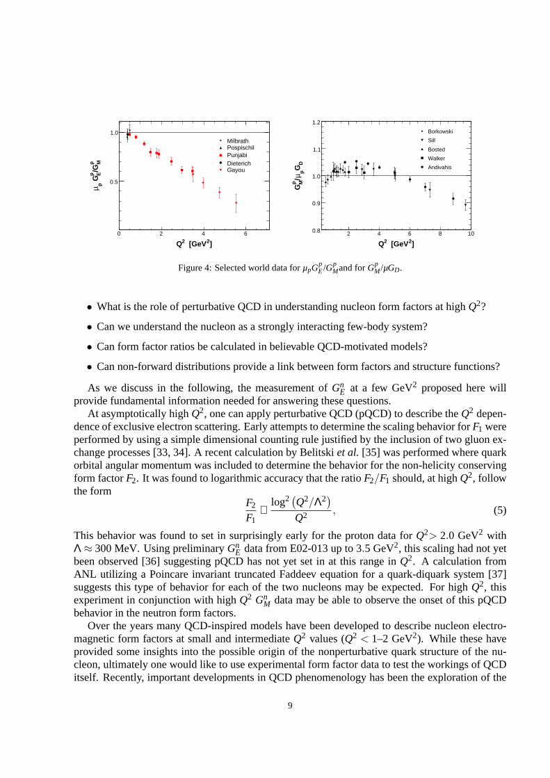
Figure 4: Selected world data forµpGpE/Gp
Mand forGpM/µGD.
• What is the role of perturbative QCD in understanding nucleon form factors at highQ2?
• Can we understand the nucleon as a strongly interacting few-body system?
• Can form factor ratios be calculated in believable QCD-motivated models?
• Can non-forward distributions provide a link between form factors and structure functions?
As we discuss in the following, the measurement ofGnE at a few GeV2 proposed here will
provide fundamental information needed for answering these questions.At asymptotically highQ2, one can apply perturbative QCD (pQCD) to describe theQ2 depen-
dence of exclusive electron scattering. Early attempts to determine the scaling behavior forF1 wereperformed by using a simple dimensional counting rule justified by the inclusion of two gluon ex-change processes [33, 34]. A recent calculation by Belitskiet al. [35] was performed where quarkorbital angular momentum was included to determine the behavior for the non-helicity conservingform factorF2. It was found to logarithmic accuracy that the ratioF2/F1 should, at highQ2, followthe form
F2
F1∝
log2(
Q2/Λ2)
Q2 , (5)
This behavior was found to set in surprisingly early for the proton data forQ2> 2.0 GeV2 withΛ ≈ 300 MeV. Using preliminaryGn
E data from E02-013 up to 3.5 GeV2, this scaling had not yetbeen observed [36] suggesting pQCD has not yet set in at this range inQ2. A calculation fromANL utilizing a Poincare invariant truncated Faddeev equation for a quark-diquark system [37]suggests this type of behavior for each of the two nucleons may be expected. For highQ2, thisexperiment in conjunction with highQ2 Gn
M data may be able to observe the onset of this pQCDbehavior in the neutron form factors.
Over the years many QCD-inspired models have been developed to describe nucleon electro-magnetic form factors at small and intermediateQ2 values (Q2 < 1–2 GeV2). While these haveprovided some insights into the possible origin of the nonperturbative quark structure of the nu-cleon, ultimately one would like to use experimental form factor data to test the workings of QCDitself. Recently, important developments in QCD phenomenology has been the exploration of the
9

generalized parton distribution (GPD) formalism [38, 39, 40], which provides model–independentrelations between inclusive and exclusive observables. For example, the nucleon elastic form fac-torsF1 andF2 are given by the first moments of the GPDs
F1(t) = ∑q
Z 1
0Hq(x,ξ, t,µ)dx andF2(t) = ∑
q
Z 1
0Eq(x,ξ, t,µ)dx, (6)
whereHq andEq are two of the generalized parton distributions,x is the standard Bjorkenx, ξ isis the “skewdness” of the reaction (Fig. 5),t is the four-momentum transfered by the electron,µis a scale parameter necessary from the evolution overQ2, analogous to DIS parton distributions,and the sum is over all quarks and anti-quarks. These may be accessed through processes suchas deeply virtual compton scattering, where the interaction is factorized into a hard part with thevirtual photon/photon interactions with an individual quark and a soft part of the residual systemwhere the GPD information is contained, Fig. 5.
Furthermore, as shown earlier by Ji [38], the moments of GPDscan yield information, accord-ing to the Angular Momentum Sum Rule, on the contribution to the nucleon spin from quarks andgluons, including both the quark spin and orbital angular momentum.
At present, experimental measurements of GPDs are scarce. Until such data becomes available,work has been done to attempt to parameterize these GPDs, which rely heavily on data fromelectromagnetic form factors and parton distributions from DIS as constraints [41, 42, 43]. Data athighQ2 for Gn
E would contribute significantly in the development of these models.
−e
γ∗
x+ξ x−ξ
t
γ
Figure 5: DVCS scattering process which allows access to GPDs.
10

3 The Double Polarization Method
In the following paragraphs we will briefly summarize the formalism used to describe cross sec-tions and asymmetries obtained in doubly polarized electron scattering experiments. We willmainly follow the approach of [49, 50]. In the Born approximation, the elastic electron nucleonscattering (e−N) cross section can be written as a sum of two parts:Σ, which corresponds tothe unpolarized elastic differential cross sectiondσ/dΩe, and a polarized part∆, which is onlynon-zero if the electron is longitudinally polarized (helicity h = ±1);
σh = Σ+h∆. (7)
The asymmetryAN for thee−N scattering cross section is defined as
AN =σ+−σ−
σ+ +σ−=
∆Σ
. (8)
The unpolarizede−N cross sectionΣ for elastic scattering off a free nucleon at rest is given by
Σ =dσdΩ
∣
∣
∣
∣
Mott
Ef
Ei
(
G2E + τG2
M
1+ τ+2τG2
M tan2(θ/2)
)
, (9)
withdσdΩ
∣
∣
∣
Mott=
α2cos2 θ2
4E2i sin4 θ
2
(10)
being the Mott cross section, which describes the scattering of a spin one-half particle from apoint-like spin one-half target. The polarized part is given by
∆ = −2dσdΩ
∣
∣
∣
∣
Mott
Ef
Ei
√
τ1+ τ
tan(θ/2)
[
√
τ(1+(1+ τ) tan2(θ/2))cosθ∗G2M +sinθ∗ cosφ∗GMGE
]
,
(11)whereθ∗ is the polar angle andφ∗ is the azimuthal angle of the target polarization in the laboratoryframe with respect to the axis of the momentum transfer (Fig.6).
θ∗
e
e’
θ φ∗e
polarization axis
ω, q
momentumtransfer
Figure 6: The kinematics of electron scattering from a polarized target.
The measured experimental asymmetry for the3−→He(~e,e′n)pp reaction is reduced compared tothis ideal~n(~e,e′n) reaction due to a number of effects. Limited polarization ofthe electron beam
11

Pbeamand the3He target,P3He, the effective polarization of the neutrons in the3He target,Pn, theaddition of nitrogen in the3He target,DN2, the dilution from accidental background events,Dback,contributions from inelastic pion production,Dπ, and reductions from nuclear effects,DFSI.
At JLab beam polarizations ofPbeam= 0.85 are routinely achieved. The polarized3He targethas been operated at average values of aboutPHe = 0.50 during experiment E02-013. Plans tocontinue to improve the maximum polarization by the polarized3He target groups are underway,with the expectation of reaching 0.65. The total spin of3He is mainly carried by the neutron, so apolarized3He target represents an effective polarized neutron target. As many authors have shown[51, 52, 53, 54, 55, 56, 57], even for a 100% polarized3He nucleus, the neutron itself has only apolarization of 0.86±0.02. Additionally, the protons in polarized3He nuclei are not completelyunpolarized, but carry a polarization of−0.028±0.004. The presence of nitrogen in the target cellleads toDN2 ≈ 0.94, and background events lead toDback= 0.95 (see Sec. 4.3 and 6). Final stateinteractions can reduce the asymmetry by a factor of 0.9∼0.95. Contributions from inelastic pionproduction may change the asymmetry by approximately 20%, and needs to be evaluated fromexperimental data.
The measured asymmetry from the neutron can now be expressedas
Aexp = PbeamP3HePnDN2DπDFSIAphys (12)
with
Aphys = −2√
τ(τ+1) tan(θ/2)GnEGn
M sinθ∗ cosφ∗
(GnE)2 +(Gn
M)2(τ+2τ(1+ τ) tan2(θ/2))
−2τ
√
1+ τ+(1+ τ)2 tan2(θ/2) tan(θ/2)(GnM)2cosθ∗
(GnE)2 +(Gn
M)2(τ+2τ(1+ τ) tan2(θ/2)). (13)
By aligning the target spin perpendicular to the momentum transfer, one gets the perpendicularasymmetry:
A⊥ = −Gn
E
GnM
2√
τ(τ+1) tan(θ/2)
(GnE/Gn
M)2 +(τ+2τ(1+ τ) tan2(θ/2)). (14)
Because(GnE/Gn
M)2 is small compared to the second term of the denominator in ourkinematics,Gn
E is nearly proportional toA⊥. To extractGnE out of this ratio, knowledge ofGn
M is necessary.At present theQ2 = 10 GeV2 Gn
M data [26] would introduce a 20% error toGnE, which is near the
sum of all other contributions to the uncertainty. The accurate extraction ofGnE will have to rely
on future highQ2 GnM measurements.
Due to the large acceptance of the BigBite spectrometer and theneutron detector array, theperpendicular spin alignment can only be made for part of theacceptance, and longitudinal contri-butions to the asymmetry have to be taken into account
A‖ = −2τ
√
1+ τ+(1+ τ)2 tan2(θ/2) tan(θ/2)
(GnE/Gn
M)2 +(τ+2τ(1+ τ) tan2(θ/2)).(15)
With the ability to reconstruct the scattering angles and the momentum transfer, and a well mea-sured magnetic holding field for the target, these corrections are under control.
12

The above discussion described scattering from a free nucleon. The general case of electronscattering from a bound nucleon was also analyzed by Donnelly [50]. Additional components,which appear in the cross section, are nulled when the cross section is integrated over the azimuthalangle of the nucleon momentum relative to the direction of the momentum transfer and the electronscattering plane. The remaining differences between the case of a free and a bound nucleon willbe addressed in Sec. 5.
13
4 Experimental Setup
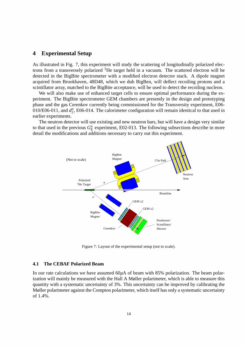
As illustrated in Fig. 7, this experiment will study the scattering of longitudinally polarized elec-trons from a transversely polarized3He target held in a vacuum. The scattered electron will bedetected in the BigBite spectrometer with a modified electron detector stack. A dipole magnetacquired from Brookhaven, 48D48, which we dub BigBen, will deflect recoiling protons and ascintillator array, matched to the BigBite acceptance, will be used to detect the recoiling nucleon.
We will also make use of enhanced target cells to ensure optimal performance during the ex-periment. The BigBite spectrometer GEM chambers are presently in the design and prototypingphase and the gas Cerenkov currently being commissioned for the Transversity experiment, E06-010/E06-011, anddn
2, E06-014. The calorimeter configuration will remain identical to that used inearlier experiments.
The neutron detector will use existing and new neutron bars,but will have a design very similarto that used in the previousGn
E experiment, E02-013. The following subsections describe in moredetail the modifications and additions necessary to carry out this experiment.
BigBiteMagnet
Preshower/
ShowerScintillator/
e−
NeutronArm
17m Path
GEM x2
GEM x2
Cerenkov
3He TargetPolarized
n
MagnetBigBen
Beamline
(Not to scale)
Figure 7: Layout of the experimental setup (not to scale).
4.1 The CEBAF Polarized Beam
In our rate calculations we have assumed 60µA of beam with 85% polarization. The beam polar-ization will mainly be measured with the Hall A Møller polarimeter, which is able to measure thisquantity with a systematic uncertainty of 3%. This uncertainty can be improved by calibrating theMøller polarimeter against the Compton polarimeter, which itself has only a systematic uncertaintyof 1.4%.
14
4.2 The Polarized3He Target
The polarized target for GEN-II will use the technique of spin-exchange optical pumping, the sametechnique that was used for GEN-I (E02-013), as well as the other polarized3He experimentsconducted in Hall A. At first glance, the proposed target for GEN-II appears quite ambitious. Thetarget we describe below will provide an effective luminosity roughly 15-16 times larger than wasthe case during GEN-I, and 7–8 times larger than the3He experiments that are running at thetime of this writing. The fundamental advancements that will provide the improved luminosity,however, have already been largely demonstrated. What distinguishes the GEN-II target fromprevious polarized3He targets is that it takes better advantage of the progress that has been madein recent years.
There are five distinct factors that play a key role in making the GEN-II target possible:
1. The introduction of alkali-hybrid mixtures to greatly increase the efficiency with which theangular momentum of photons is transferred to3He nuclei.
2. The introduction of greatly improved diagnostics that permit not just polarimetry of the3He,but also polarimetry of the alkali-metal vapors as well as the direct measurement of the alkali-vapor number densities.
3. The advent of commercially available line-narrowed high-power diode-laser arrays.
4. The recognition of the presence of a poorly understood, but measurable,3He spin-relaxationmechanism that can be characterized by something that has come to be called the “X-factor”.
5. The demonstration of convection mixing in sealed target cells with no moving parts.
Of the above mentioned points, only the first, the use of alkali-hybrid mixtures, was employedduring GEN-I. By itself, however, this made it possible to maintain a target polarization of roughly50% with 8µA of beam on target, considerably better than the range of mid-thirty to low-fortypercent polarizations that had been achieved previously. Prior to GEN-I, spin-exchange polarizedtargets generally used a single alkali metal, rubidium, in the spin-exchange process. When usingrubidium, the efficiency with which angular momentum makes its way from circularly polarizedphotons to3He nuclei is only a few percent. Alkali-hybrid technology involves the use of a mixtureof rubidium and potassium. Potassium, it turns out, is much more efficient at transferring itselectronic polarization to3He nuclei through spin exchange. When alkali-hybrid mixtures areused, the efficiency with which angular momentum is transferred can be as high as 20–30%. Thissingle advancement made it possible to achieve unprecedented target performance during GEN-I.
The second and third advancements listed above have resulted in improvements to target per-formance that are at least as significant as those that were achieved by employing alkali-hybridtechnology. For the first time, we have begun making target cells that regularly (in themajorityof those tested) achieve3He polarizations in excess of 70%. Two factors have contributed to thisimprovement. First, we have optimized the ratio of potassium to rubidium, a process that requiredmore sophisticated target diagnostics. Secondly, we have begun using a new type of commercialline-narrowed high-power diode-laser arrays. Among otherthings, the new lasers make it possibleto maintain alkali-vapor polarizations near 100% even at very high alkali number densities. The
15

polarized3He experiments that are currently running in Hall A are benefitting from these develop-ments. The transversity experiment, for instance, is running with polarizations well in excess of60% despite the fact that the experiment requires frequent flipping of the3He polarization direc-tion, which causes significant loss of polarization.
The fourth and fifth advancements are of particular relevance to GEN-II. With the implementa-tion of advancements 1–3, the rate at which we can polarize3He nuclei is sufficient to overwhelmrapid depolarization due to the electron beam, even at high beam currents of tens of microamps.As we will show below, however, the basic target-cell designthat has been used at JLab in recentyears has an intrinsic limitation. The3He is polarized in an upper “pumping chamber”, whereasthe electron beam is incident upon the polarized gas in a lower “target chamber”. The connectionbetween these two chambers has historically been accomplished using a single glass tube, referredto as the “transfer tube”. The mixing of gas between these twochambers has been dominated bydiffusion, and characterized by time constants on the orderof 30–40 minutes. While these mixingtimes have been quite adequate in the past, we are now able to polarize the gas so quickly thata substantial polarization gradient exists between the pumping chamber and the target chamber.This polarization gradient would be unacceptably large at the currents at which we plan to runGEN-II. To solve this problem, we have developed a new technique in which convection, not dif-fusion, causes the mixing of the gas. This is the fifth advancement mentioned above. Finally, thefourth advancement (which chronologically came earlier),was the identification of a previouslyunrecognized relaxation rate. This discovery, made by ThadWalker’s group at the University ofWisconsin, has made it possible for us to understand the behavior of our targets at a level of detailthat was not previously possible. For the first time, we are able to make measurements in our labthat allow us to predict with considerable accuracy the behavior that we see under full operatingconditions.
In summary, the high-luminosity GEN-II target is based almost entirely on ideas that haveeither been demonstrated previously in Hall A, or ideas thathave subsequently been tested inour lab. The “Transversity” experiment currently running in Hall A already has benefitted frompolarizations as high as roughly 70%. With a few additional features, The GEN-II target will beable to run with 60% polarization even with a beam current of 60µA, and an increased target lengthof 60 cm instead of 40 cm. The key new features that will make itpossible to go to high currentsinclude a cell that utilizes convection to enable rapid mixing, a metal target chamber, and a largerpumping chamber that will provide a bigger reservoir of polarized gas. The target will use tenspectrally-narrowed high-power diode-laser arrays. We note that some polarized3He experimentsat JLab have used as many as seven lasers in the past. In short,with the substantive advances thathave occurred with polarized3He targets in recent years, the GEN-II target is actually nota veryambitious jump at all. Rather, we are planning to take advantage of improvements that alreadyexist.
4.2.1 The principles behind the GEN-II target
The polarized3He target is based on the technique of spin-exchange opticalpumping which canbe viewed as a two step process. In the first step, an alkali-metal vapor (in our case containing amixture of potassium (K) and rubidium (Rb)) is polarized by optical pumping using radiation froma laser. In the second step, the polarized alkali-metal atoms collide with the3He atoms, transferring
16

their spin to the3He nuclei through a hyperfine interaction. For the polarized3He targets that havebeen used at JLab both the alkali vapor and the3He are contained in sealed glass cells, an exampleof which is shown in Fig. 8.
Photo Credit: A. Gavalya
Figure 8: Shown is one of the glass polarized3He target cells used during GEN-I (E02-013).
If the diffusion time between the pumping chamber and the target chamber is fast enough thatit can be neglected, the time dependence of the3He polarization has a particularly simple form
PHe(t) = PAlkγse
γse(1+X)+Γ
(
1−e−t(γse+Γ))
, (16)
wherePHe is the nuclear polarization of the3He,PAlk is the polarization of the alkali-metal vapor,γse is the rate of spin-exchange rate between the3He and the Rb, andΓ is the spin-relaxationrate of the3He nuclei due to all other processes. The factor(1+ X) accounts for what is now awell-established additional relaxation mechanism whose presence has been empirically establishedbut whose origin is unknown [58]. The factor(1+ X) has the form given because the additionalrelaxation mechanism has been seen to be roughly proportional to the alkali-metal number density.We note that the factor “X” can be measured for any particular cell, and is one of the quantitiesthat we have begun to measure for the various target cells that we produce.
The spin exchange rate can be written
γse= fpc(kKse[K]+kRb
se [Rb]), (17)
where fpc is the fraction of3He atoms that are located within the pumping chamber,kKse(k
Rbse ) is
the constant characterizing spin exchange between3He and K(Rb), and [K]([Rb]) is the numberdensity of K(Rb) atoms within the pumping chamber. It can be seen that in order to achieve highpolarizations, we must have the relaxation rateΓ << γse. In principal, if the alkali-metal num-ber density can be made arbitrarily high, the3He polarization can approach the limiting value of
17

PAlk/(1+ X). In the past, the highest alkali-metal number density that could be maintained atsomething approaching 100% was strongly limited by the available laser power. By using alkali-hybrid mixtures and line-narrowed lasers, however, it is now possible to use very high alkali num-ber densities.
The spin relaxation rateΓ contains several contributions and can be written
Γ = Γwall +Γbulk+Γbeam, (18)
whereΓwall is spin relaxation due to collisions between the3He atoms and the container walls,Γbulk is spin relaxation due to3He-3He collisions, andΓbeamis spin relaxation due to the electronbeam. For our target cells, the time constant associated with spin relaxation due to wall collisionsand bulk effects,(Γwall +Γbulk)
−1, is usually in the range of 20–40 hours. The beam depolarizationrate has been studied both theoretically [59] and experimentally [60] and is given by
Γbeam= (76,292cm2/g)ρHeLtcJbeam/NHe, (19)
whereρHe is the mass density of3He in the target chamber,Ltc is the length of the target chamber,Jbeamis the beam current in particles per unit time, andNHe is the total number of3He atoms in thetarget. The time constant associated with with beam depolarization, (Γbeam)
−1 was on the orderof 100 hours during GEN-I. For GEN-II, for our proposed target configuration, it will be about20 hours at 60µA. The GEN-II target incorporates two features that suppress depolarization dueto the electron beam. First, convection-based mixing will be used to eliminate the polarizationgradient between the pumping chamber and the target chamber. Secondly, the pumping chamberwill be substantially bigger, providing a large reservoir of polarized gas. The GEN-II target isbased on a design in which 6.8 STP liters of gas are polarized.In contrast, the GEN-I target wasbased on a design in which 3 STP liters of gas were polarized.
4.2.2 The GEN-I polarized3He target and subsequent studies.
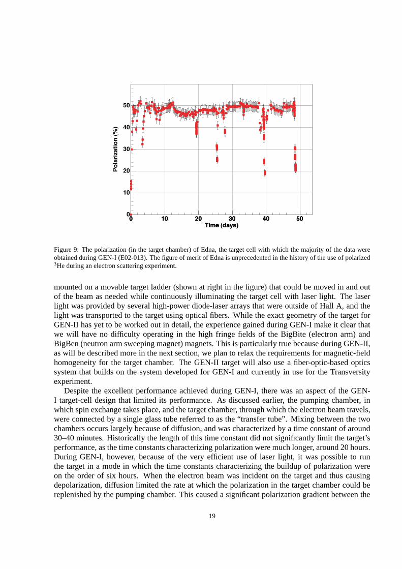
The figure of merit for the polarized3He target during GEN-I was the highest that had ever beenachieved by a polarized3He target during an electron scattering experiment. The figure of merit forthe current “Transversity” experiment is even higher still, but as only on-line data are available atthis time (the experiment is still running at the time of thiswriting), we will restrict our commentson the Transversity targets to measurements made in our lab at UVa. The polarization achieved asa function of time for the GEN-I cell “Edna”, used for the majority of our data taking, is shown inFig. 9. The polarization of the target was near or even above the 50% level for more than 50 daysof running with beam currents that were typically about 8µA. The polarization was well abovethe 40% level assumed in the original GEN-I proposal. Furthermore, while we ran at 8µA, thereis little question that the target would have performed wellat 12µA, the original design current.There were several factors that contributed to the high performance we observed, but central amongthem was the use of alkali-hybrid technology, the first time this approach was used in an electronscattering experiment.
The physical configuration of the GEN-I target is illustrated in Fig. 10. The magnetic holdingfield for the polarized3He was provided by a soft iron box that was magnetically excited usingseveral sets of coils. This technique was economical in the use of space and was effective inreducing magnetic field gradients that were held below 10 mG/cm. The glass target cells were
18
Time (days)0 10 20 30 40 50
Time (days)0 10 20 30 40 50
)%(
noit
azir
alo
P
0
10
20
30
40
50
Figure 9: The polarization (in the target chamber) of Edna, the target cell with which the majority of the data wereobtained during GEN-I (E02-013). The figure of merit of Edna is unprecedented in the history of the use of polarized3He during an electron scattering experiment.
mounted on a movable target ladder (shown at right in the figure) that could be moved in and outof the beam as needed while continuously illuminating the target cell with laser light. The laserlight was provided by several high-power diode-laser arrays that were outside of Hall A, and thelight was transported to the target using optical fibers. While the exact geometry of the target forGEN-II has yet to be worked out in detail, the experience gained during GEN-I make it clear thatwe will have no difficulty operating in the high fringe fields of the BigBite (electron arm) andBigBen (neutron arm sweeping magnet) magnets. This is particularly true because during GEN-II,as will be described more in the next section, we plan to relaxthe requirements for magnetic-fieldhomogeneity for the target chamber. The GEN-II target will also use a fiber-optic-based opticssystem that builds on the system developed for GEN-I and currently in use for the Transversityexperiment.
Despite the excellent performance achieved during GEN-I, there was an aspect of the GEN-I target-cell design that limited its performance. As discussed earlier, the pumping chamber, inwhich spin exchange takes place, and the target chamber, through which the electron beam travels,were connected by a single glass tube referred to as the “transfer tube”. Mixing between the twochambers occurs largely because of diffusion, and was characterized by a time constant of around30–40 minutes. Historically the length of this time constant did not significantly limit the target’sperformance, as the time constants characterizing polarization were much longer, around 20 hours.During GEN-I, however, because of the very efficient use of laser light, it was possible to runthe target in a mode in which the time constants characterizing the buildup of polarization wereon the order of six hours. When the electron beam was incident on the target and thus causingdepolarization, diffusion limited the rate at which the polarization in the target chamber could bereplenished by the pumping chamber. This caused a significant polarization gradient between the
19
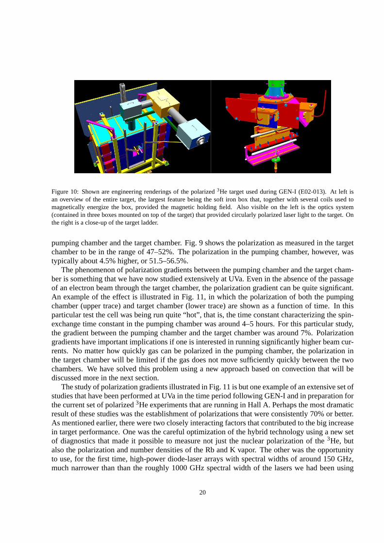
Figure 10: Shown are engineering renderings of the polarized 3He target used during GEN-I (E02-013). At left isan overview of the entire target, the largest feature being the soft iron box that, together with several coils used tomagnetically energize the box, provided the magnetic holding field. Also visible on the left is the optics system(contained in three boxes mounted on top of the target) that provided circularly polarized laser light to the target. Onthe right is a close-up of the target ladder.
pumping chamber and the target chamber. Fig. 9 shows the polarization as measured in the targetchamber to be in the range of 47–52%. The polarization in the pumping chamber, however, wastypically about 4.5% higher, or 51.5–56.5%.
The phenomenon of polarization gradients between the pumping chamber and the target cham-ber is something that we have now studied extensively at UVa.Even in the absence of the passageof an electron beam through the target chamber, the polarization gradient can be quite significant.An example of the effect is illustrated in Fig. 11, in which the polarization of both the pumpingchamber (upper trace) and target chamber (lower trace) are shown as a function of time. In thisparticular test the cell was being run quite “hot”, that is, the time constant characterizing the spin-exchange time constant in the pumping chamber was around 4–5hours. For this particular study,the gradient between the pumping chamber and the target chamber was around 7%. Polarizationgradients have important implications if one is interestedin running significantly higher beam cur-rents. No matter how quickly gas can be polarized in the pumping chamber, the polarization inthe target chamber will be limited if the gas does not move sufficiently quickly between the twochambers. We have solved this problem using a new approach based on convection that will bediscussed more in the next section.
The study of polarization gradients illustrated in Fig. 11 is but one example of an extensive set ofstudies that have been performed at UVa in the time period following GEN-I and in preparation forthe current set of polarized3He experiments that are running in Hall A. Perhaps the most dramaticresult of these studies was the establishment of polarizations that were consistently 70% or better.As mentioned earlier, there were two closely interacting factors that contributed to the big increasein target performance. One was the careful optimization of the hybrid technology using a new setof diagnostics that made it possible to measure not just the nuclear polarization of the3He, butalso the polarization and number densities of the Rb and K vapor. The other was the opportunityto use, for the first time, high-power diode-laser arrays with spectral widths of around 150 GHz,much narrower than than the roughly 1000 GHz spectral width of the lasers we had been using
20

Figure 11: Data on the polarization of the target cell Simoneas a function of time together with fits from a model thatincorporates the effects of polarization gradients due to the limited rate of diffusion between the two chambers of thetarget cell. The upper trace shows the polarization in the pumping chamber and the lower trace shows the polarizationin the target chamber. This figure illustrates the necessityof using convection instead of diffusion for targets that willbe used in high-current electron beams.
previously. With our optimized target cells, the new lasers, and our improved diagnostics guidingus, we saw huge improvement in target performance. Perhaps best of all, we have established themost detailed understanding of the physics occurring within our targets that we have ever had. Thislast point is critical, because it makes it straightforwardto design an appropriate target for GEN-II.
4.2.3 The GEN-II High-Luminosity Target Cell
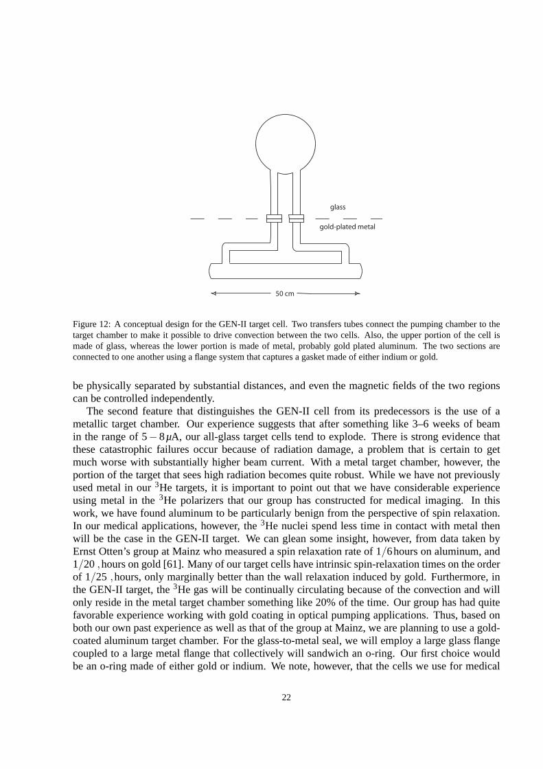
The high-luminosity GEN-II target cell represents a natural evolution of the GEN-I target cell,but incorporates two critical new features. First, insteadof relying on diffusion to move gas be-tween the pumping chamber and the target chamber, the new GEN-II cells will utilize convection.Second, the GEN-II target cells will be constructed out of both glass and metal. Specifically, thepumping chamber, in which the optical pumping and spin exchange take place, will be constructedout of glass, and the target chamber, through which the electron passes, will be constructed out ofmetal. Taken together, these two new features will make it possible to run the new target at veryhigh currents. A rough conceptual design of the GEN-II target cell is shown in Fig. 12.
Ever since adopting alkali-hybrid technology, the rate at which 3He nuclei are being polarizedin our targets is sufficient to compensate for a considerableamount of beam depolarization. Asdiscussed in the last section, however, the rate at which polarized gas in the pumping chambermoves into the target chamber is limited by diffusion. Up to this point, all polarized3He cells usedat JLab have had a geometry similar to that of the cell depicted in Fig. 8 in which a single “transfertube” connects the pumping chamber to the target chamber. Inthe GEN-II cell geometry, however,two transfer tubes are used. With this geometry, one of the transfer tubes can be heated in order todrive convection, and the gas in the two chambers can be mixedas quickly as is desired. In fact,once control is established over the mixing times, the pumping chamber and the target chamber can
21
50 cm
glass
gold-plated metal
Figure 12: A conceptual design for the GEN-II target cell. Two transfers tubes connect the pumping chamber to thetarget chamber to make it possible to drive convection between the two cells. Also, the upper portion of the cell ismade of glass, whereas the lower portion is made of metal, probably gold plated aluminum. The two sections areconnected to one another using a flange system that captures agasket made of either indium or gold.
be physically separated by substantial distances, and eventhe magnetic fields of the two regionscan be controlled independently.
The second feature that distinguishes the GEN-II cell from its predecessors is the use of ametallic target chamber. Our experience suggests that after something like 3–6 weeks of beamin the range of 5−8µA, our all-glass target cells tend to explode. There is strong evidence thatthese catastrophic failures occur because of radiation damage, a problem that is certain to getmuch worse with substantially higher beam current. With a metal target chamber, however, theportion of the target that sees high radiation becomes quiterobust. While we have not previouslyused metal in our3He targets, it is important to point out that we have considerable experienceusing metal in the3He polarizers that our group has constructed for medical imaging. In thiswork, we have found aluminum to be particularly benign from the perspective of spin relaxation.In our medical applications, however, the3He nuclei spend less time in contact with metal thenwill be the case in the GEN-II target. We can glean some insight, however, from data taken byErnst Otten’s group at Mainz who measured a spin relaxation rate of 1/6hours on aluminum, and1/20 ,hours on gold [61]. Many of our target cells have intrinsic spin-relaxation times on the orderof 1/25 ,hours, only marginally better than the wall relaxation induced by gold. Furthermore, inthe GEN-II target, the3He gas will be continually circulating because of the convection and willonly reside in the metal target chamber something like 20% ofthe time. Our group has had quitefavorable experience working with gold coating in optical pumping applications. Thus, based onboth our own past experience as well as that of the group at Mainz, we are planning to use a gold-coated aluminum target chamber. For the glass-to-metal seal, we will employ a large glass flangecoupled to a large metal flange that collectively will sandwich an o-ring. Our first choice wouldbe an o-ring made of either gold or indium. We note, however, that the cells we use for medical
22

imaging all contain a polymer-based o-ring, and that is an acceptable solution. In summary, thechallenges associated with the GEN-II target cell are not unlike the issues that we have alreadysuccessfully faced in the context of medical imaging. Some development work will be required,but the important underlying materials issues, such as the spin-relaxation properties of the neededmaterials, have already been addressed.
4.2.4 Convection Tests in a Prototype GEN-II Target Cell
As has already been emphasized, the success of the GEN-II target relies critically on our abilityto circulate the polarized gas between the pumping chamber and the target chamber using convec-tion. Indeed, this is the enabling technology for the GEN-IItarget, because it allows us to use asealed cell with no moving parts. We thus felt that demonstrating our ability to drive convectionwould remove important uncertainties regarding the GEN-IItarget design. With this in mind, weconstructed an all-glass sealed cell that approximates thebasic geometry of the GEN-II target. Thedimensions were chosen not to correspond to what we would ultimately like to build, but rather sothat the test cell could be fabricated and tested using our existing apparatus. The resulting cell isshown in Fig. 13.
Figure 13: The first prototype “convection-driven target cell. Made entirely out of glass, this cell approximates thegeometry of the proposed GEN-II target-cell geometry and isbeing used to prove the concept of mixing the gases ofthe pumping chamber and target chamber using convection.
To drive convection, a small hot-air driven heater was attached to the right-hand transfer tubeleading out of the pumping chamber. To detect and characterize the convection, a small slug of gaswas “tagged” by depolarizing it using a short pulse of resonant RF delivered by a small “zappercoil” that was wrapped around the left-hand transfer tube. The movement of the tagged slug of gaswas tracked using a set of four “pick-up coils” that were spaced equally along the length of thetarget chamber. A photograph of the instrumented prototypecell is shown in Fig. 14.
Representative data from our tests are shown in Fig. 15. Att = 0, a pulse of RF was deliveredby the zapper coil, creating a depolarized slug of gas. The polarization of the gas passing throughthe four pick-up coils was monitored by making an NMR measurements every 5 seconds using thetechnique of adiabatic past passage. Each of the four coils clearly shows the passage of the depo-larized gas as evidenced by the time dependence of the measured polarization. The first transient
23

Figure 14: The prototype convection-driven target cell is shown instrumented for tests. As described in the text, a“zapper coil” is used to tag a slug of gas, and four pick-up coils monitor the movement of the tagged slug of gasthrough the target chamber. The speed of the convection is controlled using the “convection heater”.
of reduced polarization appears in coil #1, the most upstream coil. Transients subsequently appearin each of coils #2–#4. It is interesting to note that the transient is relatively narrow as observed bycoil #1, but broadens when observed by each successive coil.This is because diffusion is causingthe slug of depolarization to spread out. Finally, we note that the data are of sufficient quality thatwe can compute the speed of the gas, which in this case, was around 20cm/min.
We were able to control the speed with which the gas moved by adjusting the temperatureof the heater attached to the left-hand transfer tube. The data shown in Fig. 15 were taken at50C. In Fig. 16, we show the results of measurements corresponding to setting our heater attemperatures between roughly 31C and 67C. Gas speeds in excess of 30cm/min were observed.At such speeds, the gas in the target chamber will be replacedwith new gas every two minutes,roughly 20 times faster than was the case during GEN-I. The implications of using convection-driven polarized3He targets are quite profound. First, we are no longer limited in the speed withwhich we can replenish gas that has been depolarized by the electron beam. In addition, however,we are for the first time in a position to physically separate the region in which the3He is polarizedfrom the region in which the3He serves as a target. Among other things, this provides considerableflexibility in the manner in which we generate magnetic holding fields, a matter that we will returnto shortly.
4.2.5 Choosing Design Parameters for the GEN-II High-Luminosity Target
Using nothing more than the formalism presented earlier in the target section, it is straightforwardto compute the expected performance for a given target design. Many of the inputs are quiteunambiguous, such as target cell geometry,3He density, and the expected depolarization due tointeraction with the electron beam. Some of the inputs are specific to a given cell, such as theintrinsic spin-relaxation rate associated with a particular target cell, and the value of the so-calledX−factor that characterizes the now well-established but poorly-understood relaxation mechanism
24

AF
P C
orre
cted
NM
R S
igna
l (m
V)
28.0
4.0
6.0
8.0
10.0
12.0
14.0
16.0
18.0
20.0
22.0
24.0
26.0
Time since Zap (s)280.020.0 40.0 60.0 80.0 100.0 120.0 140.0 160.0 180.0 200.0 220.0 240.0 260.0
Coil 1
Coil 2
Coil 3
Coil 4
Figure 15: Shown are NMR signals from the four equally-spaced pick-up coils that were mounted on the targetchamber as a function of time wheret = 0 corresponds to the creation of a depolarized slug of gas. Coil #1 was themost upstream coil, given the expected direction of flow. Transients corresponding to the passing of the depolarizedgas are clearly visible (in the expected order) for each of the four coils.
25 30 35 40 45 50 55 60 65 700
5
10
15
20
25
30
35
Heated Transfer Tube Temperature (C)(Second Transfer Tube Cooled to 24 C)
3H
e V
elo
city in T
arg
et C
ham
ber
(cm
/min
)
Convection Test 11/17/2008
Figure 16: The measured speed of the gas moving through the target chamber is plotted as a function of the temperatureof the “convection heater”. At 30cm/s, the gas in the target chamber is replaced every 2 minutes, roughly 20 timesfaster than was the case during GEN-I.
25

that scales with alkali density. While these values are cell specific, we have measured them ona sufficient number of cells that we know with confidence what is achievable. Finally there islaser power, along with its implications for the maximum number density of alkali-metal atomsthat can be maintained at very high polarization. In principle, the literature contains sufficientinformation to compute the required laser power for a particular set of operating conditions. Webelieve, however, that a more conservative approach is to formulate an estimate based on scaling.
We present in Fig. 17 (in the right-hand plot) the predicted performance for the GEN-II target.With a beam current of 60µA, a target-chamber length of 60 cm, an intrinsic cell-specific spin-relaxation rate of 1/25hrs, and an “X−”factor of 0.15, we predict a target polarization of 62%. Forcomparison, we have also calculated the expected polarization in a cell similar to what is currentlybeing used in the “Transversity” experiment, but at 60µA. Assuming diffusion to be infinitelyfast, the expected polarization would be around 45%. The difference is that the GEN-II targetincorporates a large reservoir of polarized gas in the pumping chamber, ensuring that thefractionof 3He nuclei being depolarized is smaller than would otherwisebe the case. I note also that wehave assumed in this comparison that the target chamber length of the Transversity-type cell was60 cm (not the actual length of 40 cm) so that the absolute rateof beam depolarization would bethe same for either target. Finally, when we calculate (not shown) the polarization that one wouldexpect during the existing Transversity experiment, we getroughly 70%, just as observed, at leastwhen the target polarization is not being rapidly flipped back and forth.
Figure 17: Shown are calculated “spin-up” curves for cells similar to those being used in the Transversity experiment(at left) and a cell with characteristics such as are plannedfor GEN-II (at right). For the GEN-II design, a polarizationin excess of 60% is achieved at a beam current of 60µA.
4.2.6 The Physical Configuration of the GEN-II Target
Having established the feasibility of running the GEN-II target at high luminosity, we include herea few comments on other aspects of the design.
First, the target chamber of the cell, that is, the metallic portion of the sealed polarized3He targetcell, will sit in a vacuum. While this has not been the practiceat JLab, we note that the polarized3He target cells used in both E-142 and E-154 (two experimentsat SLAC that studied the spinstructure of the neutron) sat in vacuum. At SLAC, however, this was quite challenging because
26

it meant that even the oven that provides heat to the pumping chamber needed to sit in vacuum.The GEN-II target, however, will have a metal target chamber. It will thus be straightforwardto have the target chamber sit in vacuum while the pumping chamber, along with optics, NMRcomponents, etc., sit outside the vacuum.
Next, we comment on the magnetic holding fields. For GEN-II, we will only perform NMRmeasurements on the pumping chamber, not the target chamber. Historically, the magnetic fieldhomogeneity requirements for the JLab polarized3He targets have been driven by the need tominimize polarization losses during NMR measurements. This will still be true for the pumpingchamber, but not for the target chamber. Assuming that we usea holding field of roughly 20 Gauss,the homogeneity requirement for the pumping chamber will beroughly 5–10 mG/cm. For the targetchamber, however, the requirement will be roughly 200 mG/cm, a factor of 20–40 less demanding.Furthermore, we plan to control the magnetic field at the target chamberindependentlyfrom themagnetic field in the pumping chamber. The two fields can even point in arbitrarily differentdirections. It will take roughly 2–3 minutes for gas to travel from the pumping chamber, downthrough the target chamber, and back into the pumping chamber. This is more than enough timefor the spins to adiabatically follow the magnetic field through an arbitrary change in direction withnegligible loss of polarization. One of us (Cates) used essentially this technique in an experimentat Los Alamos in which polarized muonic3He was produced by stopping muons in polarized3Hegas [62]. The holding field for the3He was adiabatically rotated once every two minutes by 180,and no measurable loss of polarization was detected. Finally, since the magnetic field surroundingthe target cell can point in an arbitrary direction, it can also be flipped at will. If done sufficientlysmoothly, we believe it should be trivial to flip the magneticfield of the target chamber in tenseconds or less. We note the limitation on the flipping speed (without polarization losses) comesnot from quantum mechanics, but from the smoothness with which the flip is accomplished. Forthe SIDIS experiment, we plan to flip the target direction once every two minutes, losing less than10% of the data-taking time in the process.
27

4.3 The BigBite Spectrometer
Scattered electrons will be detected in the BigBite spectrometer (Fig. 18). BigBite is a non-focusing large momentum and angular acceptance spectrometer that was originally designed andbuilt for use at the internal target facility of the AmPS ringat NIKHEF [63, 64]. The spectrom-eter consists of a single dipole magnet (with magnetic field approximately 1.2 T) and a detectionsystem. The current electron detector package includes three sets of multi-wire drift chambers, agas Cerenkov detector, a segmented lead glass calorimeter intwo parts knows was the preshowerand shower, and a plastic scintillator plane between the shower. Summed amplitudes over thepreshower and shower form the trigger.
Gas C
600
650
85350
650
440
20o
1700
10o
3He Target
285
CalorimeterLead Glass
GEM400x1500
GEM500x2000
MVDC500x2000
890
Scintillator
Figure 18: The BigBite spectrometer with proposed detectorstack.
4.3.1 GEM Chambers
To cope with the high rates for this experiment, the drift chambers will be replaced with gas elec-tron multiplier (GEM) detectors [65]. These detectors haveproven to be capable of operating underluminosities of 25 kHz/mm2 for the COMPASS experiment at CERN [66] and the spatial resolu-tion of each of these chambers is anticipated to be about 70µm. For two sets of two GEM chambersseparated by a distancezGEM and including multiple scattering effects, the angular resolution ofthe drift chambers can be approximated by
(δθ)2 =σ2
x
z2GEM
+
(
13.6 MeVβcp
√
x/X0 [1+0.038ln(x/X0)]
)2
(20)
whereβc is the velocity of the electron,p is the momentum of the electron, andx/X0 is thethickness of the scattering material in radiation lengths.
28

For small deflection angles from a dipole magnet, the deflection angle,θ, and the momentum,p, are related by the equation
p =e
R
B⊥ ·dlθ
, (21)
whereR
B⊥ ·dl is the field integral for the path of the electron. For electrons of momentum 3∼4 GeV and a field integral of 1.0 T·m, this would yield a typical momentum resolution ofδp/p≈0.5%.
Figure 19: The BigBite spectrometer with the current electron detector stack.
In order for us to accurately determine the scattered electron’s angular coordinates, momentum,and the position of the scattering vertex along the target, the optics of BigBite need to be studied.Data from a multi-foil carbon target and a removable lead sieve located at the front face of themagnet provide an accurate method to calibrate the angular coordinates before magnetic deflectionand a beamline scattering vertex position. Data from elastic coincidenceepscattering from a H2target will provide data to calibrate the electron momentumand will be performed for each beamenergy setting. As the kinematics for quasielastic and elastic scattering are similar, this provides themost efficient and reliable method for calibration. With thesieve plate in place, it also eliminatesthe need forB = 0 field data, which was proven difficult to extract due to prohibitively high ratesof otherwise deflected low energy particles.
4.3.2 Simulation of BigBite
Two packages of programs for the simulation of the BigBite spectrometer characteristics weredeveloped independently by V. Nelyubin [67] and S. Riordan. For this experiment, the momentumof the scattered electrons will be approximately 3.5 GeV/c for theQ2 = 10 GeV2 point, leadingto an expected momentum resolution ofδp/p of about 0.5%. The expected position resolution on
29
target along the beam isσ= 4 mm, and the expected angular resolution in both scattering planes isbetter thanσ=0.3 mrad.
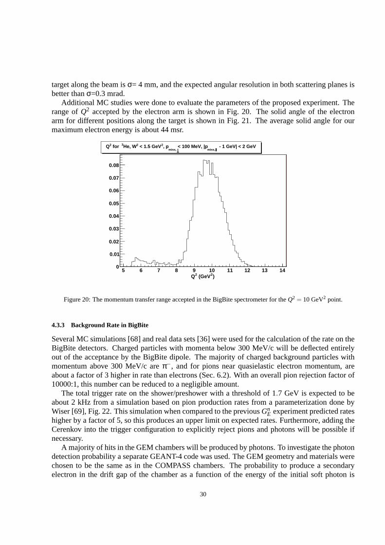
Additional MC studies were done to evaluate the parameters of the proposed experiment. Therange ofQ2 accepted by the electron arm is shown in Fig. 20. The solid angle of the electronarm for different positions along the target is shown in Fig.21. The average solid angle for ourmaximum electron energy is about 44 msr.
)2 (GeV2Q5 6 7 8 9 10 11 12 13 14
0
0.01
0.02
0.03
0.04
0.05
0.06
0.07
0.08
- 1 GeV| < 2 GeVmiss,
< 100 MeV, |pmiss,
, p2 < 1.5 GeV2He, W3 for 2Q
Figure 20: The momentum transfer range accepted in the BigBite spectrometer for theQ2 = 10 GeV2 point.
4.3.3 Background Rate in BigBite
Several MC simulations [68] and real data sets [36] were usedfor the calculation of the rate on theBigBite detectors. Charged particles with momenta below 300 MeV/c will be deflected entirelyout of the acceptance by the BigBite dipole. The majority of charged background particles withmomentum above 300 MeV/c areπ−, and for pions near quasielastic electron momentum, areabout a factor of 3 higher in rate than electrons (Sec. 6.2). With an overall pion rejection factor of10000:1, this number can be reduced to a negligible amount.
The total trigger rate on the shower/preshower with a threshold of 1.7 GeV is expected to beabout 2 kHz from a simulation based on pion production rates from a parameterization done byWiser [69], Fig. 22. This simulation when compared to the previousGn
E experiment predicted rateshigher by a factor of 5, so this produces an upper limit on expected rates. Furthermore, adding theCerenkov into the trigger configuration to explicitly rejectpions and photons will be possible ifnecessary.
A majority of hits in the GEM chambers will be produced by photons. To investigate the photondetection probability a separate GEANT-4 code was used. TheGEM geometry and materials werechosen to be the same as in the COMPASS chambers. The probability to produce a secondaryelectron in the drift gap of the chamber as a function of the energy of the initial soft photon is
30

Vertex (m)-0.4 -0.3 -0.2 -0.1 0 0.1 0.2 0.3 0.4
So
lid A
ng
le (
msr
)
0
10
20
30
40
50
Solid Angle vs. Beamline Vertex
Figure 21: The MC simulation of the BigBite solid angle versus the position on target along the beam direction.
Threshold (GeV)0.5 1 1.5 2 2.5 3 3.5
Rat
e (k
Hz)
-110
1
10
210
310-1 s-2 cm36 10× = 6.3 + 19.0 p + LnL = L
2 = 5.0 GeV2Q2 = 6.8 GeV2Q
2 = 10.2 GeV2Q
= 44 msrΩ, -1 s-2 cm36 10× = 6.3 n
Trigger Rates vs. Threshold, LnEG
Figure 22: Anticipated trigger rates for each setting.
31

shown in Fig. 23. It is about 10−3 at 100 keV and increases up to 4×10⁻³ at 1 MeV. Above 1MeV the photon efficiency (Fig. 24) increases but doesnt exceed 1%. In the same figures, bottompanels, the probability for correlated hits in two or more chambers is shown. This happens whenone photon produces secondary electrons in several chambers. One can see that such a probabilityis negligible for photon energies below 1 MeV, and the hit rates on the chambers are dominated byuncorrelated random hits.
Using data from the Transversity experiment, E06-010, which placed BigBite at 30 at 1.5 mwith a beam current of 12µA, the rate per 140 cm×35 cm chamber was 41 MHz. At our beamenergies, beam current, active area, target length, and BigBite distance, we expect an increase inrate by about a factor of 13. Estimating the BigBite drift chamber photon efficiency to be at most afactor of 5 smaller than the GEM chambers, we anticipate an overall increase in the observed ratein the drift chambers to be a factor of 65, or a rate of 4.5 kHz/mm2. This is below rates in whichthese have been demonstrated to operate.
Using information from the shower and scintillator, the area in the GEM chambers to searchfor tracks can be restricted by a factor of 10, leading to approximately 26 false hits in a 100 nstime window per plane. Current transversity tracking code operates with a time window larger bya factor of three and without using shower information, presenting an overall background rate thetracking must contend with higher by only a factor of two. This should present no problem forcurrent BigBite tracking software.
Using rates of charged particles above 300 MeV, less than 20%of events are anticipated to havemultiple tracks in the same region as the triggering track. Thex andy components of these trackscan be separated using the fixedzplane positions given by the shower and scintillator plane.
Figure 23: Top: Efficiency of registration in a single chamber of a soft photon as function of its energy. Bottom:probability for correlated hits in two or three chambers caused by a single soft photon as function of its energy. Scalesare percent.
32

Figure 24: Same as Fig. 23, but in the 1-10 MeV region.
4.3.4 Shower/Preshower
The electromagnetic calorimeter configuration consists oftwo planes of lead glass blocks whichwhich we call the preshower and shower. The preshower, located about 80 cm behind the firstGEM chamber, consists of a 2×27 plane of 37 cm×8.5 cm blocks. The shower, about 1 m behindthe first GEM chamber, consists of an 7×27 array of 8.5 cm×8.5 cm blocks. Sums over theseblocks form the physics event trigger for the experiment.
The preshower signal can be used to provide an additional method of pion rejection. By select-ing low preshower signals, a pion rejection factor of 1:50 can be achieved through optimization.Despite higher particle rates, pion rejection performanceis anticipated to be similar to that achievedfor Transversity, E06-010. By measuring the pedestal widthsand resolution for E06-010 and scal-ing to this proposal’s conditions, overall relative energyresolution for the detector is expected tobecome worse by a factor of 1.6, to aboutσδE/E = 25%.
4.3.5 Scintillator
The BigBite scintillator plane will be upgraded from the current electron detector package to a con-figuration of 80 paddles in a plane, each with dimensions 1 in.×1 in.×60 cm. For the transversityexperiment, where BigBite is at 30 using a shorter 40 cm3He target, and 12µA beam, the rate forthe scintillator plane was approximately 3.6 MHz. Using this data to provide upper limits on therates seen for our experiment, scaling to current, a longer target, and bar active area, we anticipatea rate of 270 kHz per bar. This plane will primarily be used to provide a signal for nucleon time offlight reconstruction. A time resolution of 200 ps is anticipated.
4.3.6 Gas Cerenkov
The BigBite gas Cerenkov, consists of a tank with a maximum depthof 60 cm, with 20 sphericalfocusing mirrors in a 10×2 arrangement. Each primary mirror reflects onto a secondarymirrorand in turn focuses light into a 5 in. PMT with a conical mirror to increase collection efficiency.Current commissioning has used C4F10 as a radiator, however, withn− 1 = 1.5× 10⁻³, the π
33

threshold is only about 2.5 GeV. For 12 GeV running, to provide a pion threshold of 3.5 GeV, acombination of about 50% CO2, 50% Freon-12 will be used.
For our conditions, the rate of electrons will be about 30 kHz, which in a 100 ns gate willlead to a 0.3% chance of a pion being misidentified by an accidental electron. Using standardcalculations, for a charged pion near threshold, there is a 0.1% chance of producing aδ electronabove threshold. Combined, a pion rejection factor from the Cerenkov will be about 1:250, nearspecifications. Combined with a rejection factor of 1:50 for the preshower provides a 104 overallrejection.
34

4.4 Neutron Detector
The original design of the neutron detector for this experiment is based on many considerations,including detector acceptance, efficiency, and backgroundsuppression. For this experiment wepropose using a very similar setup to that which was used in E02-013. There are several consider-ations which are specific to the conditions of the proposed experiment:
• The large kinetic energy of the neutron leads to the possibility of using high TDC thresholdsand for off–line analysis.
• The relatively low luminosity for the polarized3He target and the presence of the BigBenmagnet simplifies the background situation.
• The high velocity of the neutrons demands the largest possible distance from the target.
4.4.1 Structure of the Neutron Detector
This experiment is focused on large momentum transfer, where the recoiling neutrons have kineticenergies of 3.5 GeV, 4.4 GeV, and 6.3 GeV. Such large energiesallow a high detection efficiencyfor neutrons, and at the same time they allow us to apply relatively high thresholds to suppressbackground from low energy particles. The previous detector layout is presented in Fig. 25, similarto what will be used. The overall dimensions of the neutron arm are 4.2× 2.0× 6.2 m3. The
1
1
01
02
03
04
05
06
07
08
01
02
03
04
05
06
07
0809
10
11
12
13
14
15
16
11
09
10
12
13
14
15
1617
18
19
20
21
22
23
24
17
18
19
20
21
22
23
2425
26
27
28
29
30
31
32
26
27
28
29
30
31
32
25
33
34
35
36
37
38
39
40
33
34
35
36
37
38
39
4041
42
43
44
45
46
47
48
41
42
43
44
45
46
47
48
42
44
43
40
41
39
38
36
35
34
33
32
37
31
09
08
03
02
01
05
06
07
04
00
15
14
13
17
18
19
16
21
24
23
29
28
22
20
42
43
44
40
41
30 30
10
39
37
36
35
34
33
32
38
31
09
08
04
03
02
01
06
07
05
00
16
15
14
13
18
19
17
28
25
24
23
21
29
22
20
42
44
43
40
41
30
39
38
36
35
34
33
32
37
31
09
08
03
02
01
05
06
07
04
00
15
14
13
17
18
19
16
24
23
21
29
28
22
20
25
26
27 27
26
25
26
27
12
11
12
11
1010
11
12
28
27
29
30
25
22
23
24
26
19
20
21
13
12
15
14
07
09
10
03
05
04
02
11
16
06 06
11
16
25
22
23
24
26
19
20
21
13
12
15
14
09
10
03
05
04
02
06
28
30
27
29
31
11
16
25
22
23
24
26
19
20
21
13
12
15
14
09
10
03
05
04
02
06
11
16
25
22
23
24
26
19
20
21
13
12
15
14
09
10
03
05
04
02
07 07 07
08080808
17
1818
171717
18 18
Figure 25: Side view of the neutron detector in E02-013. The irregular bars at the top will be replaced with bars similarto the others in the plane.
35
detector will have seven layers, consisting of 30 bars of dimensions 15× 5 × 180 cm3 in thefirst three planes. In the fourth through seventh layers have40 counters. These counters havedimensions 10× 10× 180 cm3. Each neutron bar is equipped with two photomultipliers, one oneach end.
In front of every layer there is a 1.27 cm iron converter to increase the probability of a neutroninteraction in the detector. The front of the detector will be covered by a segmented veto detectorprotected by a 1.27 cm thick iron plate and a 5.04 cm thick lead plate. Between the veto countersand the front layer of the neutron bars, there will be a 1.27 cmthick iron plate and a 5.04 cm thicklead plate from low energy particles.
4.4.2 Parameters of the Neutron Detector
The solid angle of the neutron detector is approximately 40 msr at a distance of 17 m from thetarget. The aspect ratio is 1:2.5. With such a geometry, the acceptance of the neutron detectornearly matches the acceptance of the BigBite spectrometer.
The time resolution is expected to beσt = 0.3 ns and was previously achieved in E02-013.At a distance of 17 m, the 0.3 ns time resolution leads to a neutron momentum resolution ofσp = 1.5 GeV/c for a neutron momentum of 6.3 GeV/c. A missing perpendicular momentumresolution of about 100 MeV is expected.
The horizontal intersection point of the neutron with the neutron detector will be determinedutilizing the time difference between the two phototubes ofeach neutron detector, while the verticalintersection point will be defined using the segmentation ofthe neutron detector. A resolution ofabout 10 cm was achieved in both directions.
4.4.3 Parameters of the Big Ben Magnet
The 48D48 magnet from Brookhaven will be acquired as part of the Super BigBite upgrade andwill be available for this experiment. It consists of a largedipole magnet which provides a fieldintegral of about 1.7 T·m, allowing for quasielastic protons to be sufficiently deflected to allowclear differentiation from neutrons. The active field volume has an opening of 46×25 cm (vertical× horizontal), matching the aspect ratio of the neutron arm, and a depth of 48 cm, Fig. 26.
The placement of this magnet will be 1.6 m away from the target, which would normally inter-fere with the beamline. To accommodate this, modifications will be made to the iron yoke suchthat the beamline will pass through the magnet itself, Fig. 27. GEANT4 simulations show that thethe field within this region will be 70 Gauss over 70 cm, and is small enough such that deflectionsof the beam towards the beam dump will not be problematic.
The field configuration will be such that positively charged particles will be deflected upwardsaway from the hall floor. For a field integral of 1.7 T·m, protons of momentum 6.3 GeV/c willbe deflected 80 mrad, which translates to a displacement of 1.2 m. Including expected detec-tor resolution, thepmiss,⊥ distribution will be similar to what was seen in E02-013, so cuts ofpmiss,⊥< 100 MeV, will be appropriate. Monte Carlo simulations show a contamination of chargedquasielastics to be negligible, Sec. 6.3.
The presence of the magnet also works to sweep low energy charged particles from the targetaway from the neutron arm. Particles of momentum less than 1.3 GeV will be entirely swept
36

Figure 26: BigBen magnet schematic.
Target
Left coil
Right coil Beam line opening
A A
173"
92"
Right yoke
Beam
Figure 27: BigBen magnet cuts such that the exiting beamlinemoves through the magnet.
outside of the neutron arm acceptance. This greatly reducesthe amount of charged low energybackground.
4.4.4 Expected Background Rates and Shielding
In the proposed experiment the 60µA electron beam will pass through a 60 cm long3He target.The total thickness of the glass entrance window is 120µm and the side window 1.6 mm. A largemajority of particles leaving the target in the direction ofthe neutron arm are photons. For the firstGn
E experiment, which had no such benefit from a magnet, a flux of 3×1038 Hz/cm2 at 7.5 µA.was observed. This corresponded to an observed rate per bar of about 300 kHz. From GEANTsimulations, a detector at 17 with a 8.8 GeV beam is expected to have photons rates higher by afactor of four versus a detector at 27 with a 3.2 GeV energy beam. The neutron arm will be furtherback, reducing the active solid angle by a factor of three anda target of 60 cm instead of 40 cm
37

will be used. With the addition of the BigBen magnet, the rate will be decreased by an additionalfactor of 5.
From the firstGnE experiment, the rate on each neutron arm bar was about 300 kHzgiven a
beam current of 7.5 µA. For our 8.8 GeV2 beam, we can expect a 1300 kHz rate, or a total flux of1.3×1039 Hz, which, with a nominal TDC deadtime of 50 ns, gives an overall electronic deadtimeof 6.5%, within our tolerance.
4.4.5 Veto Detector
Plastic scintillator counters had previously been used to distinguish neutrons from protons. Withthe addition of the BigBen magnet, this method for identification is no longer necessary. However,these planes will remain in place and can be used for normal hadron detection.
38

5 Helicity Asymmetry in 3 ~He(e,e′n) and the Ratio ofGnE/Gn
M
A full analysis of this subject requires calculations whichare presently under development in Refs.[71, 72]. Below we summarize the topics which are important ingredients in these calculations orwill be used to provide consistency checks and show preliminary results of the calculations fromM. Sargsian.
5.1 Nucleons in the Nuclear Medium
There are several processes related to the influence of the nuclear medium on the structure of abound nucleon. One of the best known is the nuclear EMC effect, which shows that the structurefunction of the nucleus is suppressed at largexB j relative to that of the deuteron. While a definitiveexplanation of this effect is still elusive, it is clear thata quantitative description of the effectrequires, in addition to the conventional nucleon and mesondegrees of freedom, some dynamicaleffects involving sub-nucleonic degrees of freedom (see e.g. [73, 74, 75, 76]). However, twofactors make the EMC effect controllable in the proposed measurement. First, in models wherethe EMC effect is proportional to the virtuality of the boundnucleon, which would potentiallylead to a distortion of the intrinsic structure of the bound nucleon, the restriction to small valuesof missing momenta and invariant mass will substantially suppress any such distortion and thecorresponding onset of the EMC effect. Secondly, the measured asymmetry will be less sensitiveto nucleon structure modifications and the bulk of the EMC effect will be less revealed in the formfactor ratios.
Color Transparency (CT) is another effect (see e.g. [77]) which can potentially hinder theextraction of the neutron form factor at highQ2. This effect has been investigated in quasi-elasticproton knock-out by electrons from nuclei forQ2 from 1 to 8 GeV2 [78]. Such studies probethe propagation of the nucleon through nuclei and test the effect of the nuclear medium on theproton knockout cross section. The aforementioned experiment [78] observed no signature for CTup to Q2=8 GeV2 in the kinematics of restricted missing momentum and energy. Moreover, thecomparison with theoretical calculations demonstrated that the Glauber approximation adequatelydescribes the data for a wide range of nuclei (ranging from the deuteron to iron). Thus for theQ2 of the present proposal, one expects that the Glauber approximation will reliably describe thefinal state interactions in the3
−→He(~e,e′n)pp reaction.
A study of polarization observables in the reactiond(~e,e′~p) was made at JLab up toQ2 =1.6 GeV2 [79]. Studies of polarization transfers in the reaction4He(~e,e’~p) was also made at Mainz[80] and up toQ2 = 2.6 GeV2 at JLab [81]. These experiments found that the ratio of the compo-nents of the polarization of the recoiling protonP′
x/P′z can be smaller than the same ratio for a free
nucleon target by about 10% (Figs. 28 and 29). The same effects which contribute to this modifi-cation need to be taken into account for the analysis of3−→He(~e,e′n)pp. The density of a3He nuclei,which is between the densities of2H and4He nuclei, will lead to an averaging of these mediumeffects. Calculations from J. Udias predict a reduction of the ratioP′
x/P′z of 8% in 4He compared
to hydrogen, whereas in3He the reduction is only a 4% effect [82].
39

(GeV^2)2Q0.4 0.6 0.8 1 1.2 1.4 1.6
H) Z/P
’X
/(P
’d)
Z/P
’X
(P’
0.8
0.85
0.9
0.95
1
1.05
1.1
1.15
1.2
Hu et al. (JLab)
Polarization Transfer Ratio - Deuterium
Figure 28: The ratio of the polarization transfer components (P′X/P′
Z)D/(P′X/P′
Z)H for a bound proton. relative to thefree proton [79].
Figure 29: The ratio of the polarization transfer components (P′X/P′
Z)4He/(P′X/P′
Z)H for a bound proton. relative to thefree proton [81].
40

5.2 3Heas a Neutron Target
Experiments utilizing3He targets as effective neutron targets have been carried out for a wide rangeof beam energies at Bates, Indiana, NIKHEF, Mainz, HERMES, SLAC and, for the last decade,in JLab Hall A. During the past decades there have been several theoretical discussions about thepossibility of using a3He target to study the properties of the elastic electromagnetic form factorsof the neutron [10, 57, 83]. In addition, calculations for inclusive and exclusive electron scatteringreactions from3He have been performed [83, 84, 85, 86].
The neutron polarization in3He and the three-nucleon wave function have been computed byanumber of authors using several different methods, including the approach via Faddeev equations[87], and the variational approach [51, 53, 54, 55, 56, 88]. These are now well established, and theerror introduced through uncertainty in the wave functionswill be very small.
The semi–exclusive reaction3−→He(~e,e′n)ppallows one to fix the values of the missing momentaand energy of the struck neutron which are the key parametersfor controlling the size of nucleareffects. A cut on the transverse components of the neutron momentumpmiss,⊥ is more effectivein this task than a cut on the longitudinal componentpmiss,‖ [71]. In the proposed experiment thevalue of the asymmetry will be measured as a function ofpmiss,⊥ in the range 0-100 MeV/c.
5.3 Qualitative Assessments of Nuclear Effects in the Extraction of GnE/Gn
M from Semi-exclusiveA(e,e′N)X Reactions
The key observation driving the proposed measurement is that it is possible to select small mo-menta in the3He wave function by requiringpmiss,⊥<100 MeV/c. This is the case because thegood convergence of the integralψ(k)dk (normalized as
R
ψ2(k)d3k = 1) leads to the selection ofvery small momenta in the wave function of3He, even though the cut onpmiss,‖ is rather large(1.5 GeV/c).
Additionally, these suppress small non-nucleonic admixtures in the wave function and theysignificantly suppress the final state interactions, since the struck nucleon is rather far from othernucleons. Most of the rescattering in these kinematics moves nucleons to largerpmiss,⊥ and hencethey do not greatly affect asymmetries calculated in the PWIAin order to extractR=Gn
E/GnM.
The following is the assessment of nuclear effects that may affect this extraction, and somequalitative estimations indicating which corrections will be possible to estimate more quantita-tively.
1. Finite acceptance effects. Because the experiment will measureGnE within a finite interval of
missing momentapmiss, the integration will smear out the extractedR. An averaging schemewhereA⊥ andA‖ are expanded out in powers of the ratioGE/GM developed for the previousGn
E experiment will be used [89].
2. Off-shell effects. The uncertainty associated with off-shell effects can be estimated by apply-ing the different off-shell prescriptions for calculationof nucleon currents. However, sincethe momenta of the struck nucleons are small, these effects,which are proportional top2
m/m2N,
should be strongly suppressed.
3. Meson Exchange Effects. The choice of highQ2 causes a significant suppression of mesonexchange effects in the extraction ofR. At Q2> 1 GeV2 the overall additionalQ2 dependence
41

of the MEC amplitude as compared to the PWIA amplitude will be(1+ Q2/Λ2)−2, whereΛ2 = 0.8−1 GeV2 (see e.g. [71]).
4. Delta Isobar Contribution. This effect should be small because of the restrictions onpmiss. Ifone assumes the sameQ2 and energy dependence of the elastic electromagnetic form factoras of theN∆ → NN rescattering amplitude, one is able to estimate the∆ contribution usingthe FSI amplitude but taking into account the fact that it corresponds to the largerpmiss,‖ inthe argument of the nuclear wave function. This gives the upper limit of the∆ contribution.
Pre-existing∆-isobars in3He have a rather small probability – about 2% – and they alsohave substantially larger average transverse momenta thannucleons. Hence the cut on smallaverage nucleon momenta will lead to further suppression. This is a potential backgroundsince there can be a transitionγ∗∆0 → n. From the violation of the Bjorken sum rule one canexpect the∆ contribution integrated over all momenta to be on the level of 4% times the ratioof the∆N form factor and theNN form factor. An additional small factor mentioned above isthe cut on momenta – so qualitatively one may get an effect on the scale of 1-2%.
5. Final State Interactions. The major advantage is that at high Q2 the eikonal approximationis applicable when the rescattering amplitude is practically energy-independent. First wediscuss FSI due to diagonalnp→ np rescattering. In the case of the factorized approximationthe uncertainty comes from the accuracy of the calculation of FSI contributions, which is lessthan 10%. The comparison of eikonal calculations with JLab data demonstrated very goodagreement for Nuclear Transparency starting with the deuteron and going up to iron [78].
In the case of smallpmiss,⊥, the overall effect of FSI for the3He target is about 10%, thus theuncertainty due to the accuracy of FSI is 1-1.5%. The theoretical calculations will allow anestimate of this contribution.
Calculations regarding these effects for3He at highQ2 are currently underway by J. M. Lagetand M. Sargsian. We anticipate having results regarding these effects by the end of January2009.
To summarize, it appears that corrections to the impulse approximation will be significantly lessthan 10% (expected on the level of 2-5%), and most of these effects will be possible to correct for.
5.4 Preliminary Results of the GEA Calculation
GEA [71], a code based on the generalized eikonal approximation, was used for the calculationsof A⊥ shown in Fig. 30. The asymmetries were calculated for a beam energy of 3.244 GeV andassuming thatGn
E follows the Galster parameterization. The following cuts on the components ofmissing momenta were applied:pmiss,⊥ less than 50 MeV/c andpmiss,‖ less than 250 MeV/c. Theinvariant mass cut wasW = 0.94±0.05 GeV. The upper solid line presents the results of the codefor a free neutron at rest. The lower solid line with smaller values ofA⊥ is a naive estimate of theasymmetry based on the neutron carrying 86% of the polarization of 3He. The dash line presentsthe results of the PWIA calculation. The dotted line is the results of the DWIA calculation. Thedash-dotted line presents the DWIA calculation with Charge Exchange (CE) effects included. Theeffect of CE is about 5.5% atQ2= 1 GeV2 and drops to 3.6% atQ2= 4 GeV2 , in agreement with
42
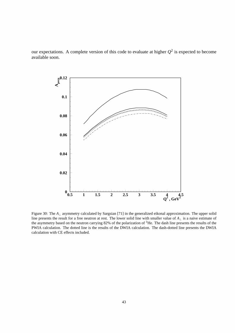
our expectations. A complete version of this code to evaluate at higherQ2 is expected to becomeavailable soon.
Q2 , GeV2
Ape
rp
0
0.02
0.04
0.06
0.08
0.1
0.12
0.5 1 1.5 2 2.5 3 3.5 4 4.5
Figure 30: TheA⊥ asymmetry calculated by Sargsian [71] in the generalized eikonal approximation. The upper solidline presents the result for a free neutron at rest. The lowersolid line with smaller value ofA⊥ is a naive estimate ofthe asymmetry based on the neutron carrying 82% of the polarization of3He. The dash line presents the results of thePWIA calculation. The dotted line is the results of the DWIA calculation. The dash-dotted line presents the DWIAcalculation with CE effects included.
43

6 Quasi-Elastic Scattering atQ2 of SeveralGeV2
In this section we will discuss the physics and background contributions to the data and the methodof separating the quasi-elastic scattering (QES) events from the background. Several physics pro-cesses contribute to the background which the detectors will see, including inelastic scatteringassociated with pion electroproduction and quasi-elasticscattering from the protons in3He. In-elastic scattering associated with pion production will bediscussed in the first subsection. Chargedpions overlapping electrons in BigBite can be suppressed by using particle identification, as dis-cussed in the second subsection. The suppression of quasi-elastic scattering from the protons in3He will be performed magnetically and will be discussed in the third subsection. The accidentalbackground in the data comes from accidental coincidences due to the high rates of low energyphotons, neutrons, and pions, which will be discussed in Sec. 6.4.
6.1 Selection of the QES Events
The first step of an extraction ofGnE is the selection of the quasi-elastic scattering events. The
previousGnE experiment used MC simulations of QES and pion production toevaluate background
contributions.From the previous experiment, we examine data fromQ2 = 1.7 and 3.5 GeV2. Quasielastic
events were selected by placing cuts onpmiss,⊥, pmiss,‖, mmiss, and a pseudo-invariant mass wherethe initial nucleon is assumed to be at rest. This invariant mass correlates very closely withxbjk.For these measurements, separation between the quasielastic events and inelastic background canbe seen, Figs. 31 and 32. For the preliminary analysis of thisexperiment, cuts were placed conser-vatively to eliminate the dependence on corrections from Monte Carlo simulations.
We rely on tight cuts onpmiss,⊥ to suppress larger contributions from final state interactions.For this experiment, we anticipate thepmiss,⊥ distribution be be similar to that seen in E02-013,Fig. 33. By placing similar cuts at 100 MeV, we also help separation from inelastic contributions.
For our proposed kinematics, this separation is not expected to be as clean due to apmiss,‖ res-olution of σ = 1.5 GeV/c, close to a factor of 10 worse. Because of thepmiss,‖ resolution, cutson missing mass will be ineffective at removing pions production events near threshold. However,placing cuts onpmiss,‖ will still be useful in eliminating background and events where the nucleonhad additional interactions before reaching the neutron arm. In light of this, it will be critical tomake a correction on the asymmetry.
For the cross section, one can use DIS or exploit quark hadronduality. The asymmetry willbe obtained in the data. By assuming small variations in the observed asymmetry across scales ofthe invariant mass width due to Fermi smearing, a deconvolution between the elastic and inelasticasymmetries can be performed. Such a method would have proved to have been successful in theE02-013 data. In this data, a smooth variation of the asymmetry between quasielastic and inelasticdominated regions was seen, Fig. 34. This deconvolution canbe performed through a maximumlikelihood method where the likelihood for an observed asymmetry is given by
f (Ai |Ainelas,Aelas,αi,Ni) = exp
[
−Ni (Ai −αiAelas− (1−αi)Ainelas)
2
2(1−A2i )
]
, (22)
44

Figure 31:pmiss,‖ vs.W from 3He for E02-013, (top)Q2 = 1.7 GeV2 and (bottom)Q2 = 3.5 GeV2.
whereAi is the observed asymmetry in theith bin, where the bin is some arbitrary subset of data,AinelasandAelasare the inelastic and elastic asymmetries,Ni is the number of statistics in the bin,andαi is the fraction of statistics that are (quasi)elastics.αi for each bin will be determined by aMonte Carlo simulation.
To find the parametersAinelasandAelas, one solves the equations given by
0 =∂ lnL∂Ax
=∂ ln(∏i f (Ai))
∂Ax, (23)
for asymmetryAx wherex is inelas or elas. This analysis will utilize bins acrosspmiss,⊥ andW2, where higherpmiss,⊥ values are dominated by inelastics.W2 will be kept below two pionproduction such that the same production channels as at lower W2 will be selected.
Contributions from inelastics for our cuts will be on the order of 25%, Fig. 35. Cuts onpmiss,⊥ are more severe than used in E02-013 due to the higher inelastic background rates, Fig. 36.As we are only interested in inelastic events within only a couple hundred MeV of the quasielasticpeak, production of more than one pion is highly suppressed.For the previousGn
E data, parame-terizations of single pion production cross sections and asymmetries from MAID were availableso such a deconvolution technique was not necessary.
From local quark-hadron duality in spin dependent observables, constraints can be made regard-ing the asymmetry contributions. Quark-hadron duality hasbeen shown for polarized3He structure
45

Figure 32:pmiss,⊥ vs.W from 3He for E02-013, (top)Q2 = 1.7 GeV2 and (bottom)Q2 = 3.5 GeV2.
functionsg1 for Q2 of at least 2 GeV2 and global duality ing2 down toQ2 = 1 GeV2 [90, 91, 92,93]. At higherQ2, duality is expected to hold more strongly.
From E02-013, this asymmetry was found to be the same sign andwithin a factor of two smallerthan the quasielastic asymmetry for allQ2 points, Fig. 34. The quasielastic asymmetry will be-come smaller by about a factor of two forQ2 = 10 GeV2. The range inxbjk for the E02-013’sQ2 = 3.5 GeV2 point and this proposal’sQ2 = 10 GeV2 point both range fromx = 0.93 tox = 1,allowing for explicit use of quark-hadron duality in spin observables. From this, it is reasonable toestimate that the inelastic asymmetry contributions will be within a factor of two of the quasielasticasymmetry.
As inelastic events are anticipated to contribute about 25%of the statistics to the quasielasticsample, an inelastic asymmetry a factor of two different than the quasielastic asymmetry will re-quire a correction on the order of 15∼ 30%. Inelastic asymmetry values near that of the quasielas-tic asymmetry would require much smaller corrections. We anticipate that we will be able to deter-mine the correction to within 5% relative to the value of the asymmetry through the deconvolutionmethod described above.
46

Figure 33:pmiss,⊥ from 3He for E02-013,Q2 = 3.5 GeV2.
6.2 Pions in BigBite
The contribution of pions in the electron arm can be evaluated using a parameterization of thecharged pion cross sections [69]. As the scattering events of interest are quasielastic, they aretypically of the highest energy. However, due to Fermi-smearing, the difference in momentumobserved in BigBite from the momentum that would be expected from elastic scattering has a halfwidth of approximately 300 MeV. Use of this parameterization shows that the number of pions toelectrons is expected to be about 3:1. Through use of the preshower calorimeter and gas Cerenkov,a total pion rejection factor of 104 is expected. Unrejected pions could only contribute less than0.1% to the physical asymmetry,Aphys, which is negligible for our anticipated error.
The background from the glass windows of the target cell and other windows will be cut out inthe analysis by using cuts on the reconstructed vertex alongthe target.
6.3 Quasielastics from the Protons in3He
The rate of quasielastics from the bound protons in3He is about factor of 12 higher than in theprocess under study neglecting the relative detection efficiency between protons and neutrons.Protons with momentum 6.3 GeV/c will be shifted 1.2 m on the face of the neutron arm allowingfor cuts onpmiss,⊥ to primarily provide proton/neutron differentiation. Dueto finite resolution andthe natural width ofpmiss,⊥, there will be some overlap between the two. For the expectedmag-netic separation contributions of protons will be negligible with our anticipated cuts ofpmiss,⊥ of100 MeV 37.
6.4 Accidental Background
Overall background rates in the neutron arm are expected to be about two or three times that seenin the first Gn
E experiment. For that analysis, neutron arm hits with reconstructedβ > 1 wereshifted in time by a constant chosen such that the quasielastic region would be entirely populatedby only accidental background. This produces a set of data with an accidental background rate anddistribution identical to the experimental conditions. By applying an identical set of cuts to theshifted data, the contributions from accidental background can be accurately quantified.
47

Figure 34: Helicity dependent asymmetry from E02-013 atQ2 = 1.7 (top) and 3.5 GeV2 (bottom) vs. invariant masswith large cuts. Asymmetry and cross section values from MAID agree very well with data.
For the previousGnE experiment, the overall background contributions were found to be 1−2%
for neutron arm bar rates of 400 kHz. These events will then contribute only 2−6%, which shouldpresent no difficulty for the analysis.
6.5 Analysis of the Corrected Asymmetry and Extraction ofGnE/Gn
M
After obtaining the asymmetry,Aphys, corrected for background and polarizations, contributionsfrom bothA‖ andA⊥ must be separated in through some method due to the large angular acceptanceof the electron arm. Through a power expansion ofAphys in terms of the ratioGE/GM to sufficientorder, the problem reduces to solving a polynomial of finite order. This method was used for E02-013 and is described in [89]. SinceGE/GM is small, an expansion to 5th order will be sufficient.The systematics of theA‖ calculation are expected to be less than 0.001 for an angularalignmentaccuracy of 1 mr.
48

W2 GeV2
∆σ/∆
W2 1
0-38 cm
2 /GeV
2
Ebeam=6.6 GeV
BigBite & BigHANDp⊥ < 0.1 GeV/c
0
1
2
3
-2 0 2 4 6
W2 GeV2
∆σ/∆
W2 1
0-38 cm
2 /GeV
2
Ebeam=8.8 GeV
BigBite & BigHAND
p⊥ < 0.1 GeV/c
0
0.2
0.4
0.6
0.8
-2 0 2 4 6
Figure 35: Quasielastic and inelastic contributions forQ2 = 6.8 GeV2 (top) andQ2 = 10 GeV2 (bottom) with cuts onpmiss,⊥< 100 MeV.
49

W2 GeV2
∆σ/∆
W2 1
0-38 cm
2 /GeV
2
Ebeam=6.6 GeV
BigBite & BigHAND
p⊥ = 0.1 - 0.2 GeV/c
0
0.5
1
-2 0 2 4 6
W2 GeV2
∆σ/∆
W2 1
0-38 cm
2 /GeV
2
Ebeam=8.8 GeV
BigBite & BigHAND
p⊥ = 0.1 - 0.2 GeV/c
0
0.1
0.2
0.3
-2 0 2 4 6
Figure 36: Quasielastic and inelastic contributions forQ2 = 6.8 GeV2 (top) andQ2 = 10 GeV2 (bottom) with cuts on100< pmiss,⊥< 200 MeV.
50

(GeV)miss,
p0 0.1 0.2 0.3 0.4 0.5 0.6 0.7 0.8
0
0.005
0.01
0.015
0.02
0.025
0.03
0.035
0.04Protons
Neutrons
with BigBen Magnetmiss,
p
Figure 37: Neutron and deflected proton quasielastic distributions inpmiss,⊥ at Q2 = 10 GeV2. Cuts near 100 MeVwill sufficiently eliminate quasielastic proton contributions.
51

7 Proposed Measurements
7.1 Kinematics
To choose which is the best combination of beam energy and scattering angle to measureGnE for a
givenQ2, one has to evaluate the figure-of-merit (FOM). In our case, theFOM is given by
FOM =R(θ)
1−A2exp
, (24)
whereR(θ) is the counting rate, which itself is proportional to the product of the cross section, theeffective target length, the beam current, and the acceptance of the particular spectrometers used.In Fig. 38 theFOM is plotted as function of the beam energy at a fixedQ2 of 10 GeV2. To studythe influence of the value ofGn
E itself, theFOM has been calculated assuming thatGnE follows the
variations of the Galster parameterization. For a givenQ2, theFOM increases for higher beamenergies, which corresponds to detecting the electron at smaller scattering angles. The variation ofGn
E does not change the general behavior of theFOM.
Beam Energy (GeV)6 7 8 9 10 11 12
f.o
.m. (
Arb
itra
ry U
nit
s)
-3910
-3810
-3710
Figure of Merit
Galster = 0.2 GnEG
Galster = 1.0 GnEG
Galster = 1.8 GnEG
Galster = 2.6 GnEG
Figure of Merit
Figure 38: TheFOM as function of the beam energy at fixedQ2 = 10.0 GeV2. An increase in the beam energytranslates into smaller electron scattering angles and higher momenta of the recoiled electron.
The minimum angle that BigBite may be set to without technical difficulty is about 34, whichcorresponds to the available beam energy of 8.8 GeV. The other two kinematics were chosen toprovide about 40% higherQ2 from the prior point. Table 1 summarizes the proposed kinematics.
7.2 Asymmetry and Rate Estimates
The asymmetryAphys in e− n scattering is related to the experimentally measured asymmetryAexp = (N+−N−)/N via the equation
Aphys=Aexp
PbeamP3HePnDN2DFSIDπDback, (25)
52

Q2 Ei θe pe θn pn
(GeV2) (GeV) (deg) (GeV/c) (deg) (GeV/c)5.02 4.400 48.0 1.73 21.6 3.496.77 6.600 34.0 3.00 22.2 4.4410.18 8.800 34.0 3.38 17.5 6.29
Table 1: The three proposed kinematics.
where the values of the various polarizations and dilutionscan be found in Table 3.The following rate estimates are based on scattering from a free neutron usingGn
E = GGalsterandGn
M from a parameterization by Kelly [27]. Radiative corrections further reduce the number ofuseful events by roughly 10%.
Q2 rate Aexp GnE/Gn
M(GeV2) (Hz)
5.02 0.146 -0.0581 -0.17706.77 0.081 -0.0547 -0.191810.18 0.010 -0.0292 -0.2098
Table 2: Rate estimates for this proposal. We assume a targetpolarizationP3He of 60%, a beam polarizationPbeamof85% an average beam current of 60µA, a viewable target length of 55 cm, and a solid angle of 44 msrfor the electronarm. Furthermore, this rate is calculated assuming that we detect the neutrons with an efficiency of 90% and cutsreduce statistics by 75%.
To help minimize the contribution of inelastic background,we used a Monte Carlo to evaluatethat these cuts will reduce the number of statistics to about25%, Fig. 39. This Monte Carlo wasused to reproduce data seen in experiment E02-013, Fig. 40. The anticipated rates and asymmetriesusing these assumptions, are shown in Table 2.
7.3 Error Estimates and Beam Time Request
The uncertaintyδAphys can be expressed as
(
δAphys
Aphys
)2
=
(
δAexp
Aexp
)2
+∑(
δPi
Pi
)2
+∑(
δDi
Di
)2
, (26)
where the sums run over all the contributions of polarizations and dilutions. The beam polarizationin Hall A can be measured with the Compton and the Møller polarimeter to better than 2%. Bothpolarimeters are standard equipment in Hall A. The polarization of 3He can be measured with arelative uncertainty of 4%, the polarization of the neutrons in 3He is known to 2%.
The statistical uncertainty isδAexp,stat = sqrt(1−A2exp)/N. To extractGn
E from the measuredAphys, Eq. 13 has to be evaluated. Investigating the error propagation in this equation, taking anexpansion ofAphys in Gn
E/GnM to first order gives
δ(
GnE
GnM
)
= δAphys2√
τ(1+ τ) tan(θ/2)sinθ∗ cosφ∗
τ+2τ(1+ τ) tan2(θ/2). (27)
53
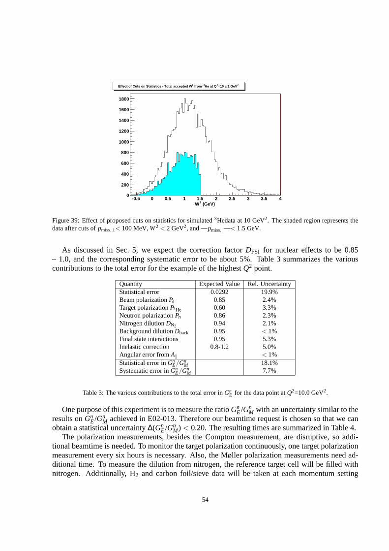
(GeV)2W-0.5 0 0.5 1 1.5 2 2.5 3 3.5 4
0
200
400
600
800
1000
1200
1400
1600
1800
2 1 GeV±=10 2He at Q3 from 2Effect of Cuts on Statistics - Total accepted W
Figure 39: Effect of proposed cuts on statistics for simulated3Hedata at 10 GeV2. The shaded region represents thedata after cuts ofpmiss,⊥< 100 MeV,W2 < 2 GeV2, and —pmiss,‖—< 1.5 GeV.
As discussed in Sec. 5, we expect the correction factorDFSI for nuclear effects to be 0.85– 1.0, and the corresponding systematic error to be about 5%.Table 3 summarizes the variouscontributions to the total error for the example of the highest Q2 point.
Quantity Expected Value Rel. UncertaintyStatistical error 0.0292 19.9%Beam polarizationPe 0.85 2.4%Target polarizationP3He 0.60 3.3%Neutron polarizationPn 0.86 2.3%Nitrogen dilutionDN2 0.94 2.1%Background dilutionDback 0.95 < 1%Final state interactions 0.95 5.3%Inelastic correction 0.8-1.2 5.0%Angular error fromA‖ < 1%Statistical error inGn
E/GnM 18.1%
Systematic error inGnE/Gn
M 7.7%
Table 3: The various contributions to the total error inGnE for the data point atQ2=10.0 GeV2.
One purpose of this experiment is to measure the ratioGnE/Gn
M with an uncertainty similar to theresults onGn
E/GnM achieved in E02-013. Therefore our beamtime request is chosen so that we can
obtain a statistical uncertainty∆(GnE/Gn
M) < 0.20. The resulting times are summarized in Table 4.The polarization measurements, besides the Compton measurement, are disruptive, so addi-
tional beamtime is needed. To monitor the target polarization continuously, one target polarizationmeasurement every six hours is necessary. Also, the Møller polarization measurements need ad-ditional time. To measure the dilution from nitrogen, the reference target cell will be filled withnitrogen. Additionally, H2 and carbon foil/sieve data will be taken at each momentum setting
54

Figure 40: E02-013 Monte Carlo results for invariant spectra atQ2 = 3.5 GeV2. The spectra are reproduced well for(top) near raw and (bottom) full quasielastic cuts.
to help calibrate the BigBite optics. We expect an overhead of 20% for these studies. Duringthe experiment, two configuration changes are necessary. These changes include a change of thebeam energy, changes of the position neutron detector array, and adjustments or replacement ofthe polarized3He target. Each configuration change will take approximately one shift. We further-more request 48 hours of beamtime for initial calibration runs. In total we request 1384 hours ofbeamtime to perform the proposed measurement, as detailed in Table 5.
55
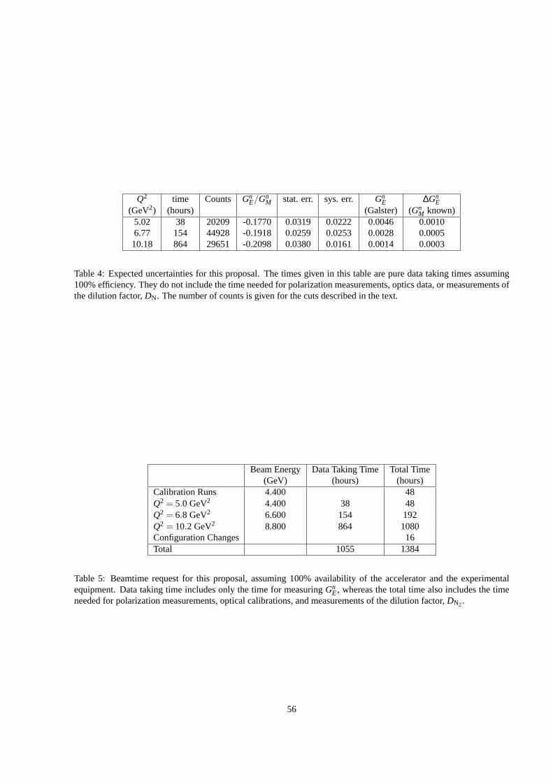
Q2 time Counts GnE/Gn
M stat. err. sys. err. GnE ∆Gn
E(GeV2) (hours) (Galster) (Gn
M known)5.02 38 20209 -0.1770 0.0319 0.0222 0.0046 0.00106.77 154 44928 -0.1918 0.0259 0.0253 0.0028 0.000510.18 864 29651 -0.2098 0.0380 0.0161 0.0014 0.0003
Table 4: Expected uncertainties for this proposal. The times given in this table are pure data taking times assuming100% efficiency. They do not include the time needed for polarization measurements, optics data, or measurements ofthe dilution factor,DN. The number of counts is given for the cuts described in the text.
Beam Energy Data Taking Time Total Time(GeV) (hours) (hours)
Calibration Runs 4.400 48Q2 = 5.0 GeV2 4.400 38 48Q2 = 6.8 GeV2 6.600 154 192Q2 = 10.2 GeV2 8.800 864 1080Configuration Changes 16Total 1055 1384
Table 5: Beamtime request for this proposal, assuming 100% availability of the accelerator and the experimentalequipment. Data taking time includes only the time for measuring Gn
E, whereas the total time also includes the timeneeded for polarization measurements, optical calibrations, and measurements of the dilution factor,DN2.
56

8 Conclusions
We request 1386 hours to measureGnE atQ2=5.0, 6.8, and 10.2 GeV2 through a measurement of the
cross section asymmetry of the reaction3−→He(~e,e′n)pp. This experiment will take place in Hall A,utilizing the BigBite spectrometer to detect electrons scattered off the Hall A polarized3He target,and an array of scintillators to detect the recoiling neutron. There are no other measurements ofGn
E at these momentum transfers and knowledge of the neutron electric form factorGnE is essential
for the understanding of the nucleon structure. Furthermore, it is a necessary input in the analysisand interpretation of processes involving the electromagnetic interaction with nuclei. We proposeto measureGn
E/GnM to an accuracy of∆Gn
E/GnM= 0.06, which would bring its precision to a level
comparable with that of the other Sachs form factors in this kinematical regime.The kinematics of our measurements emphasize the sameQ2 range studied for the proton. For
these large momentum transfers it was found that the charge and magnetic current distributions inthe proton are markedly different at short distances. It is an intriguing question to see if a similartendency is duplicated in the neutron. Furthermore, pQCD made clear predictions on how theseform factors should scale at arbitrarily highQ2. Measuring at relatively high momentum transferswill also open additional dimensions for testing the modelsof the nucleon form factors in thegeneralized parton distribution framework.
57

References
[1] J. J. Kelly, Phys. Rev. C66065203 (2002)
[2] M. Joneset al., Phys. Rev. Lett.84 , 1398 (2000).
[3] O. Gayouet al., Phys. Rev. Lett.88, 092301 (2002).
[4] V. E. Krohn and G. R. Ringo, Phys. Rev.148, 1303 (1966).
[5] L. Koester, W. Nistler, and W. Waschkowski, Phys. Rev. Lett. 36, 1021 (1976).
[6] A. I. Akhiezer, L. N. Rozensvaig and I. M. Shmushkevich, JETP33, 765 (1957).
[7] N. Dombey, Rev. Mod. Phys.41, 236 (1969).
[8] A. I. Akhiezer and M. P. Rekalo, Sov. J. Part. Nucl.3, 277 (1974).
[9] R. Arnold, C. Carlson, and F. Gross, Phys. Rev.C 23, 363 (1981).
[10] B. Blankleider and R. M. Woloshyn, Phys. Rev.C 29, 558 (1984).
[11] M. Meyerhoffet al., Phys. Lett. B327, 201 (1994).
[12] J. Beckeret al., Eur. Phys. J, A6, 329 (1999).
[13] D. Roheet al., Phys. Rev. Lett.83, 4257 (1999).
[14] J. Bermuth,et al., Phys. Lett. B564(2003) 199.
[15] I. Passchieret al., Phys. Rev. Lett.82, 4988 (1999).
[16] C. Herberget al., Eur. Phys. J.A5, 131 (1999).
[17] M. Ostricket al., Phys. Rev. Lett.83, 276 (1999).
[18] E. Geis,et al., Phys. Rev. Lett.101, 042501 (2008)
[19] R. Madey,et al., Phys. Rev. Lett.91, 122002 (2003).
[20] G. Warren,et al., Phys. Rev. Lett.92, 042301 (2004).
[21] D. Glazieret al., Eur. Phys. J.A 24, 101 (2005).
[22] R. Schiavilla and I. Sick, Phys. Rev. C64041002 (2001).
[23] S. Galsteret al., Nucl. Phys. B32, 221 (1971).
[24] J. Lachniet, Ph.D. Thesis, Carnegie Mellon University,Pittsburgh, PA, USA (2005).
[25] J. Lachniet,et al., arXiv:0811.1716
[26] S. Rock,et al., Phys. Rev. D46, 24 (1992).
[27] J.J. Kelly, Phys. Rev. C 70 (2004) 068202
58

[28] M. A. Shupeet al., Phys. Rev. D19, 1929 (1979).
[29] G. Miller, Phys. Rev. Lett.99, 112001 (2007).
[30] C. Carlson and M. Vanderhaeghen, Phys. Rev. Lett.100, 032004 (2008).
[31] L. Andivahiset al., Phys. Rev. D50, 5491 (1994).
[32] R. G. Arnoldet al., Phys. Rev. Lett.57, 174 (1986);A.F. Sill et al., Phys. Rev. D48, 29 (1993).
[33] S. J. Brodsky and G. Farrar, Phys. Rev. Lett.31, 1953 (1973).
[34] S. J. Brodsky and G.P. Lepage, Phys. Rev. D22, 2157 (1981).
[35] A.V. Belitsky, X.D. Ji, F. Yuan, Phys. Rev. Lett.91092003 (2003).
[36] S. Riordan, Ph.D. Thesis, Carnegie Mellon University, Pittsburgh, PA, USA (2008).
[37] M .S. Bhagwat, I. C. Cloet, C. D. Roberts, arXiv:0710.2059 [nucl-th]
[38] X. Ji, Phys. Rev. D55, 7114 (1997); Phys. Rev. Lett.78, 610 (1997).
[39] A.V. Radyushkin, Phys. Lett. B380, 417 (1996).
[40] A.V. Radyushkin, Phys. Rev. D56, 5524 (1997).
[41] M. Diehl, T. Feldmann, R. Jakob, and P. Kroll, arXiv:hep-ph/0408173
[42] P. Kroll, arXiv:hep-ph/0612026v1
[43] M. Guidal, M.V. Polyakov, A.V. Radyushkin, and M. Vanderhaeghen, arXiv:hep-ph/0410251v1
[44] A.V. Radyushkin, Phys. Rev. D58, 114008 (1998).
[45] M. Diehl, T. Feldmann, R. Jakob, and P. Kroll, Eur. Phys. J. C 8, 409 (1999).
[46] P. Kroll, PiN Newslett.15, 205 (1999).
[47] K. Goeke, M. V. Polyakov, and M. Vanderhaeghen, Prog. Part. Nucl. Phys.47, 401 (2001).
[48] J. Ralston, P. Jain and R. Buney, Proceedings of the Conf. on Intersections of Particle andNuclear Physics, Quebec City, (2000), ed. Z. Parseh and M. Marciano, AIP Conf. Proc. No.549 (AIP, New York, 2000), p. 302.
[49] T. W. Donnelly and A. S. Raskin, Ann. Phys. (N.Y.)169, 247 (1986).
[50] A. S. Raskin and T. W. Donnelly, Ann. Phys. (N.Y.)191, 78 (1989).
[51] C. Ciofi degli Atti, and S. Scopetta, Phys. Lett. B404, 223 (1997).
[52] R. M. Woloshyn, Nucl. Phys. A496, 749 (1989).
[53] J. L. Friaret al., Phys. Rev. C42, 2310 (1991).
59

[54] C. Ciofi degli Atti, S. Scopetta, E. Pace and G. Salme, Phys.Rev. C48, 968 (1993).
[55] R. W. Schulze and P. U. Sauer, Phys. Rev. C562293 (1997).
[56] F. Bissey, A. W. Thomas, and I. R. Afnan, Phys. Rev. C64, 024004 (2001).
[57] R. W. Schulze, P. U. Sauer, Phys. Rev. C48, 38 (1993).
[58] E. Babcock, B. Chann, T. G. Walker, W. C. Chen and T. R. Gentile, Phys. Rev. Lett.96,083003 (2006).
[59] K. D. Bonin, T. G. Walker and W. Happer, Phys. Rev. A37, 3270 (1988).
[60] K. P. Coulter, A. B. McDonald, G. D. Cates, W. Happer and T. E.Chupp, Nuc. Inst. and Meth.in Phys. Res.A276, 29 (1989).
[61] A. Deninger, W. Heil, E. W. Otten, M. Wolf, R. K. Kremer andA. Simon, Eur. Phys. J. D38,439 (2006).
[62] N. R. Newbury, A. S. Barton, P. Bogorad, G. D. Cates, M. Gatzke, B. Saam, L. Han,R. Holmes, P. A. Souder, J. Xu, and D. Benton,Laser Polarized Muonic Helium, Phys. Rev.Lett. 67, 3219 (1991).
[63] D. J. J. de Langeet al., Nucl. Instr. and Meth.A 406, 182 (1998).
[64] D. J. J. de Langeet al., Nucl. Instr. and Meth.A 412, 254 (1998).
[65] F. Sauli, Nucl. Instr. and Meth. A386, 531 (1997).
[66] B. Ketzeret al., Nucl. Instr. and Meth. A.535, 314 (2004).
[67] V. Nelyubin, private communication.
[68] P.V. Degtyarenko, “Applications of the Photonuclear Fragmentation Model to Radiation Pro-tection Problems”, Proceedings of the Second Specialist’sMeeting on Shielding Aspectsof Accelerators, Targets and Irradiation Facilities (SATIF2), 12-13 October 1995, CERN,Geneva, Switzerland, p. 67; P.V. Degtyarenko, M.V. Kossov,H-P. Wellisch, Chiral InvariantPhase Space Event Generator, I. Nucleon-antinucleon annihilation at rest, Eur. Phys. J. A8,p. 217 (2000).
[69] D. E. Wiser, Ph.D. Thesis, University of Wisconsin-Madison (1977) (unpublished).
[70] T. Blaichet al., Nucl. Instr. and Meth.A 314, 136 (1992).
[71] M. M. Sargsian, arXiv:nucl-th/0110053 and private communication.
[72] J. M. Laget, private communication.
[73] R. L. Jaffe, F. E. Close, R. G. Roberts and G. G. Ross, Phys. Lett. B 134, 449 (1984).
[74] L. L. Frankfurt and M. I. Strikman, Nucl. Phys. B250, 143 (1985).
[75] D. F. Geesaman, K. Saito and A. W. Thomas, Ann. Rev. Nucl. Part. Sci.45, 337 (1995).
60

[76] G. A. Miller and J. R. Smith, arXiv:nucl-th/0107026.
[77] L. L. Frankfurt, G. A. Miller and M. Strikman, Ann. Rev. Nucl. Part. Sci.44, 501 (1994).
[78] K. Garrowet al., arXiv:hep-ex/0109027.
[79] B. Hu et al., Phys. Rev. C73, (2006) 064004.
[80] S. Dieterichet al., Phys. Lett. B500, 47 (2001).
[81] S. Strauchet al., Phys. Rev. Lett.91, 052301 (2003).
[82] J. M. Udias, private communication.
[83] J. M. Laget, Phys. Lett. B273, 367 (1991).
[84] C. Ciofi degli Atti, E. Pace, G. Salme, Phys. Rev. C51, 1108 (1995).
[85] J. Golak it et al., arXiv:nucl-th/0110060.
[86] C. Ciofi degli Atti and L. P. Kaptari, arXiv:nucl-th/0110062.
[87] L. D. Faddeev,Mathematical Aspects of the Three-Body Problem(Daniel Davey and Co.,Inc., New York, 1965).
[88] R. M. Woloshyn, Nucl. Phys.A496, 749 (1989).
[89] G. B. Franklin,http://www.jlab.org/ ˜ franklin/gen/Gen_Asymmetry_Corrections.pdf
[90] W. Melnitchouk, R. Ent, C. E. Keppel, Phys. Rept.406, (2005).
[91] P. Solvignonet al., Phys. Rev. Lett.101, 182502 (2008).
[92] M. Amarianet al., Phys. Rev. Lett.92, 022301 (2004).
[93] P. L. Anthonyet al., Phys. Lett. B553, 18 (2003).
61