Embed Size (px)
Citation preview

Degree project inCommunication Systems
Second level, 30.0 HECStockholm, Sweden
Z I X U A N S O N G
Router based Deployment and Network Security
A Network based Home surveillance/monitoring system
K T H I n f o r m a t i o n a n d
C o m m u n i c a t i o n T e c h n o l o g y

A Network based Home
surveillance/monitoring system
Router based Deployment and
Network Security
Zixuan Song
2011/6/4
Examiner and Academic Supervisor: Prof. Gerald Q. Maguire Jr.
School of Information and Communication Technology
Royal Institute of Technology (KTH)
Stockholm, Sweden

i
Abstract
Home surveillance/monitoring systems are widely used nowadays. An intelligent surveillance system can provide multiple functions for uses. The assumption underlying this thesis project is that a home surveillance system can help people manage their homes better.
The thesis presents two investigations into an intelligent home surveillance system implementation. First we will focus on the development of a router platform, which can manage the cameras connected to an intelligent home surveillance system. Such a system will include at least one router, one or more cameras. Some of these cameras will be connected by wireless links. Each camera will be dynamically allocated an IP address. The system will manage and control the various elements of the home surveillance/monitoring system via the network. Second, we will examine potential network security solutions, and choose a suitable solution.
A key result of this thesis project is that SRTP and MIKEY are suitable for use in a home surveillance/monitoring system and together they provide authentication and privacy for the information from the camera (and potentially other information). This privacy is an important aspect of a home surveillance/monitoring system, since improper use of this information could be damaging to the homeowner’s privacy and personal integrity.
Key words: home surveillance/monitoring system, router platform development, network security, SRTP, MIKEY.

ii
Sammanfattning
Hem övervakning / övervakningssystem används ofta nuförtiden. En intelligent övervakningssystem kan ge flera funktioner för användningsområden. Antagandet bakom detta examensarbete är att ett hem övervakningssystem kan hjälpa människor att hantera sina hem bättre.
I avhandlingen presenteras två utredningar till ett intelligent hem övervakningssystem genomförande. Först kommer vi att fokusera på utvecklingen av en router plattform som kan hantera kameror anslutna till ett intelligent hem övervakningssystem. Ett sådant system kommer att inkludera minst en router, en eller flera kameror. Några av dessa kameror kommer att vara anslutna trådlösa länkar. Varje kamera kommer att allokeras dynamiskt en IP-adress. Systemet kommer att hantera och styra de olika delarna av hemmet övervakning / övervakningssystem via nätverket. För det andra kommer vi att undersöka möjliga lösningar nätsäkerhet, och välja en lämplig lösning.
Ett viktigt resultat i denna avhandling är att SRTP och MIKEY är lämpliga för användning i ett hem övervakning / övervakningssystem och tillsammans ger autentisering och integritet för den information från kameran (och eventuellt andra uppgifter). Denna sekretess är en viktig aspekt i ett hem övervakning / övervakningssystem, eftersom felaktig användning av denna information skulle vara skadligt för villaägare privatliv och personlig integritet.
Nyckelord: hem övervakning / övervakningssystem, router plattform utveckling, nätverkssäkerhet, SRTP, MIKEY.

iii
Acknowledgements
At the point of finishing this paper, I would like to express my sincere thanks to all those who have lent me a hand in the course of my thesis project. First of all, I would like to take this opportunity to express my sincere gratitude to my supervisor, Prof. Gerald Maguire, who has given me much useful advices on my writing, and has tried his best to improve my thesis. Secondly, I would like to express my gratitude to Vultura AB who offers me this thesis project. Last but not least, I would like to thank both my classmates and my colleagues at Vultura AB who give me a lot of suggestions. Without their help, it would be much harder for me to finish my project and this thesis.

v
Table of Contents
Abstract ................................................................................................................... i Sammanfattning ..................................................................................................... ii Acknowledgements ............................................................................................... iii Table of Contents ................................................................................................... v Table of Figure ...................................................................................................... vii Table of Tables ....................................................................................................... ix List of Acronyms and Abbreviations ..................................................................... xi 1 Introduction ..................................................................................................... 1
1.1 Background ............................................................................................ 1 1.2 Overview of this thesis project .............................................................. 2
1.2.1 Scenario ........................................................................................ 2 1.2.2 Structure of the thesis system ...................................................... 3 1.2.3 Hardware and Software platform................................................. 4 1.2.4 Problem statement of this thesis work ........................................ 5
1.3 Structure of the thesis ........................................................................... 6 2 Related Work .................................................................................................... 7
2.1 Router Development ............................................................................. 7 2.1.1 IP Camera tools ............................................................................. 7 2.1.2 Internet Configuration Methods .................................................. 8 2.1.3 IPv4 and IPv6 ................................................................................ 8
2.2 Network Security ................................................................................. 10 2.2.1 Security requirements ................................................................ 10 2.2.2 Security Problems on Layers ...................................................... 12 2.2.3 Authentication ............................................................................ 14 2.2.4 Cryptography .............................................................................. 14 2.2.5 Integrity ...................................................................................... 16 2.2.6 Key Management protocols ....................................................... 16
3 Router based Deployment ............................................................................. 18 3.1 Communication Channel for Cameras ................................................. 18
3.1.1 Working Procedure ..................................................................... 19 3.1.2 Software Development ............................................................... 20
3.2 Allocating an IP address for a camera ................................................. 23 3.3 Camera Information Management ...................................................... 24
4 Network Security Solution ............................................................................. 26 4.1 Security goals and challenges .............................................................. 26 4.2 SRTP ..................................................................................................... 27
4.2.1 Introduction to SRTP/RTP ........................................................... 27 4.2.2 Format of SRTP/SRTCP Packets ................................................... 28

vi
4.2.3 Keys and Parameters of SRTP ..................................................... 30 4.2.4 Replay Protection ....................................................................... 31 4.2.5 Security Algorithms in SRTP/SRTCP ............................................ 31 4.2.6 SRTP Packet Processing .............................................................. 32
4.3 MIKEY ................................................................................................... 33 4.3.1 Overview of MIKEY ..................................................................... 33 4.3.2 Methods of Key Transport and Exchange ................................... 36 4.3.3 Key Calculation for MIKEY .......................................................... 38 4.3.4 Pre-defined algorithms ............................................................... 39
4.4 Implementation ................................................................................... 39 4.4.1 Design of SRTP Modules ............................................................. 39 4.4.2 Design of MIKEY Modules .......................................................... 41 4.4.3 Security Algorithm Implementation ........................................... 44
5 Analysis .......................................................................................................... 45 6 Conclusions and Future Work ........................................................................ 48 References ............................................................................................................ 51

vii
Table of Figure
Figure 1-1: Home Video Surveillance System Based on IP Network ............................ 2 Figure 1-2: Structure of Gardio system ........................................................................ 4 Figure 1-3: Working process of Gardio system ............................................................ 4 Figure 3-1: main software development process ....................................................... 21 Figure 3-2: iterate interface to broadcast packet. ...................................................... 22
Figure 3-3:Incoming data processing on router ...................................................... 23
Figure 4-1: An example of the format of a SRTP packet [16] ..................................... 29 Figure 4-2: An example of the format of a Secure RTCP packet [16] ......................... 29 Figure 4-3: SRTP keys derivation ................................................................................ 30 Figure 4-4: peer to peer and simple one to many scenarios. .................................... 34 Figure 4-5: many to many without a centralized control unit scenario. .................... 34 Figure 4-6: many to many with a centralized control unit scenario. ......................... 35 Figure 4-7: Overview of MIKEY key management procedure. [24] ............................ 36 Figure 4-8: MIKEY packet format in pre-shared key mode. [24] ................................ 37 Figure 4-9: MIKEY packet format in public-key encryption.[24] ................................ 37 Figure 4-10: MIKEY packet format in DH key exchange mode.[24] ........................... 38 Figure 4-11: SRTP modules ......................................................................................... 40 Figure 4-12: flow chart of MIKEY message processing .............................................. 43 Figure 5-1: analysis chart of three testing group ....................................................... 47

ix
Table of Tables
Table 2-1: the comparison of operation times of public key and secret key cryptography ........................................................................................... 15
Table 3-1: Packet sent from IP camera tool. ............................................................... 19 Table 3-2: Incoming UDP packet from a camera ........................................................ 19 Table 4-1: mandatory to implement, optional and default transforms in SRTP
and SRTCP [16] ........................................................................................ 32 Table 4-2: Constant values for the derivation of keys from TGK.[24] ........................ 39 Table 4-3: Constant values for the derivation of keys from an
envelope/pre-shared key.[24] ................................................................. 39 Table 5-1: The longest time to receive data from the cameras ................................. 46 Table 5-2: Analysis of the results ................................................................................ 46


xi
List of Acronyms and
Abbreviations
CGA Crypto Generated Address CSB Crypto Session Bundle DHCP Dynamic Host Configuration Protocol DHCPv6 DHCP for IPv6 IEEE Institute of Electrical and Electronics Engineers, Inc. LAN Local area network MAC Media Access Control MIKEY Multimedia Internet Keying NDP Neighbor Discovery Protocol OUI Organizationally unique identifier RF Radio frequency RTP Real-time protocol SCTP Stream Control Transmission Protocol SEND Secure Neighbor Discovery Protocol SPINS Security Protocols for Sensor Networks SRTP Secure real-time protocol TCP Transport control protocol
TEK Traffic-encryption Key
TGK TEK Generation Key
TLS Transport layer security
UDP User datagram protocol
VOIP Voice over IP
Wi-Fi Wireless Fidelity – a wireless LAN protocol device compatible with IEEE 802.11
WLAN Wireless local area network WSN wireless sensors network

Introduction
1
1 Introduction
Today many homeowners have a home surveillance/monitoring system. Traditionally these systems have been built in an ad hoc fashion with direct wired connections between the control center and all of the sensors. This is changing due to use the use of local area network technology for the interconnections (be they wired or wireless) and the fact that the control system is increasingly connected to the Internet. The connection to the Internet enables home owners (and potentially others) to access information collected by the home security and monitoring system from any place in the Internet.
This chapter provides some background about the problem area and then gives a more detailed problem statement.
1.1 Background
Nowadays, many intelligent applications with multiple functions are becoming part of our daily lives due to the developments in networking, computing, and communications technologies. Surveillance systems are utilized in many places for public & private security, such as banks, supermarkets, and environments which are hazardous or inaccessible for human beings (for example, in environments which with poisonous gases, or very low or high temperatures).
Since computers and network are widespread, many new network based applications are appearing in our homes. Although home surveillance systems are used in a small fraction of homes, the number of people deploying such systems is gradually increasing as more and more functions are implemented by such a system. While initially such systems provided only entry alarms (to deter theft) or smoke & fire alarms (to automatically summon the fire department), later systems incorporated temperature measurements, detectors for water leaks, etc. These systems help people manage their homes more easily, provide improved security, and enable the home owner to know what happens inside or around their home.
A home surveillance/monitoring system may include video cameras, terminals, sensors, actuators, and severs. More generally, such a system can be used for monitoring or controlling devices. Typically the network transfers data from sensors to a server, from which the user can request information. Similarly the user can send commands via the server to sensors and actuators to control devices. These systems are increasingly connected via a gateway (with firewall) to the internet. As a result home owners can both monitor their homes and control devices in their homes via the internet or other IP network.
Surveillance systems based on IP networks have become mainstream products in recent years. Large numbers of images and other forms of data can be transmitted in

reagraintsurapphar
varTh
1.
targbriare spe
1.
durvac
l time thoudually evolvelligent manveillance sylication-cendware can e
Figure 1-ious terminae communic
Figure 1-1: H2 Ove
This sectioget for a neef descriptio
used to crecific problem
2.1 Sce
Some vacing vacatioation home
ugh the intved from onnagement system is ntric design easily be ad
1 shows a als. A cam
cation links
Home Video erview
on begins etworked hon of the streate such m that this
enario
cation housn time. Hs every da
ranet or Inly the tradiystem. Com
more flexibof these n
ded accord
typical nera is just ocan be wire
Surveillance of thi
by describinome surveilucture of tha system. thesis proje
o
es are locaomeowners y. Therefore
2
nternet. Mtional secur
mpared to anle, reliable,etworked sing to the u
etworked hne of the ed or wirel
System Bases thes
ng the usagllance/monhe system anThe section ect will attem
ted in ruracannot ea
e, a surveil
oreover, thrity monitoralog survei and lowe
urveillance ser’s specifi
ome video many types ess links.
d on IP Netwis pro
e scenario titoring systnd then the
ends with mpt to solv
l areas, andsily check olance syste
e surveillanring functionllance syster in cost. Bsystems, neic needs.
surveillanof sensors th
ork ject
hat we will em. This ishardware ana clear des
e.
d they mighon the com is needed
Introd
nce system ns to beco
em, a netwoBecause o
ew software
ce system hat can be u
consider as followed nd softwarscription o
ht be used nditions of d to infor
uction
has me an
rked f the e and
with used.
s the by a
e that f the
only their
m the

Introduction
3
homeowner if the house has been broken into or the occurrence of an accident, such as fire, floods, water leaks, etc. With such a networked product, users can use common terminals (such as a PC or cellular phone) to check on their home at any time. If there are any changes which may endanger the house, the alarm process generates a notification that will be sent to the homeowner’s e-mail box or cell phone.
The services that can be provided by such a system can also be very convenient for families with children. When the children play in different rooms, using this surveillance system the parent(s) can easily know where each child is, when a child leaves one room and enters another room. For school age children, when the children come home, their parents may still be at work, but the child (or children) can use the surveillance system to set up a conference call to their parent(s).
Today these systems are an intelligent product integrating multiple functions, and future developments will port the user interface to different terminals -- enabling people to better manage their home and do it more easily than they can do at present. The following subsections will describe the structure of the current product whose further development is the focus of this thesis.
1.2.2 Structure of the thesis system
This thesis project took place at Vultura AB. The product is named Gardio. Figure 1-2 shows the overall structure of Gardio. Gardio is a home surveillance system based on IP network, it is composed of servers, routers, cameras, control panels and other terminals which provide different platforms to control and manage objects in the home. The cameras (and other sensor) form the first layer of this system. These devices are responsibility for sensing the environment and sending data (such as images) to a router.
The router assigns an IP address to each camera and other network attached device using the dynamic host configuration protocol (DHCP) [2] when the device is connected to the Gardio local area network (LAN). These routers and cameras are located in the homes of users. A web interface is used as a control panel to control the camera(s) and other devices via home surveillance/monitor application that is deployed on the router; therefore, users can control and of the functions of Gardio system in their home via any web browser. This is expected to be very convenient for users, but this assumes that the home router is connected to the Internet (or intranet) and that suitable security mechanisms are used so that only authorized users can access any of the devices inside the home. We assume that the user will use a web browser running on some terminal to access the system’s web interface via the Internet. Additionally, the application can send specific data to remote servers (for example, to enable a remote alarm monitoring service).
The reason for deploying this software on the router is that most homes now have some sort of home router and this router is powered on at all time, whereas the homeowner’s personal computer might be turned off when not being used. Deploying

Introduction
4
the software on the router also enables the server to be remotely located and shared with many users. This type of router is often referred to as a “home gateway”.
Figure 1-2: Structure of Gardio system 1.2.3 Hardware and Software platform
Figure 1-3 describes the working process of Gardio. Generally speaking, IP cameras continuously collect images and send them to router. The data analysis software on the router (such as a face identification algorithm) will process the images. If there is a person moving into a room, the router will send an alarm message and image to the server. The server can send alarm messages to terminals via the internet.
Communicate with cameras
Camera information management Network security& System optimization
Images analysis ( face identification ) Figure 1-3: Working process of Gardio system
Server Collect data and images
IP Camera
Router Platform
Send to router Send to server

Introduction
5
In this thesis, we mainly focus on the software developed to be deployed upon the router. The router we selected for the project is the Edimax Technology Limited Company model 3G-6210 [25]. This router is manufactured in Taiwan. This router has a Wi-Fi wireless LAN interface. It also has a 3G model. It is currently the smallest wireless 3G router with the open source code available in the market. Its compact design enables it to even be carried by mobile users; hence the Gardio system can easily be deployed where ever a user might want. Another reason that we chose this router is the 3G-6210n has a built-in rechargeable Lithium-ion battery, with sufficient power for the device to wirelessly access the Internet via a 3G modem card for up to 1.5 hours. The processor is an ECONA CNS-1102 made by Cavium Networks [3]. It is based on an ARM processor with a 32-bit core, specifically a high performance ARM922-compatible RISC processor with a clock speed of 200MHz and 32M bytes of memory. The router has quite low power consumption (less than 2 watts). We developed additional software to run on this platform in order to create a router optimized to support cameras for a video surveillance system.
The IP cameras generally used in Gardio are the Foscam 8908, manufactured by Foscam Intelligence Limited Company, a Chinese company. This camera supports DHCP, UDP, and TCP/IP. A Common Gateway Interface (CGI) command is used to control cameras in order to get a video stream. The camera is equipped with a Wi-Fi interface that follows the IEEE 802.11b/g wireless standards. The camera also has a LED to operate in the dark.
The major functions developed on router were shown in figure 1-3. The software platform on router is embedded Linux with the core linux2.6. New applications can be added into the router using tftp. We will use router platform to communicate with cameras, control them using CGI commands, upload the required information to server, and carry out the operations specified via the user interface. Some software will be implemented on router platform to ensure the Gardio system is secure, flexible and reliable. Images analysis software has already been developed and deployed on the router, hence this aspect of the system is not addressed further in this thesis. We will introduce the functions that we have implemented Chapters 3 and 4.
1.2.4 Problem statement of this thesis work
In this thesis, we will focus on the additional software that we will deploy on the router and how it supports the cameras. We will describe the basic functions of this software, and the new functions that we need to implement to support the cameras. In this thesis project, additional code has been developed and deployed on the router to analyze data from cameras and to manage the identity and configuration of the cameras.
The problem addressed in this thesis project can be divided into two parts. The first part is the additional software to be deployed on the router in order to find, configure, and manage the cameras. The second part concerns changes made to the software to improve the system’s security. Security is important because of the sensitive nature of having cameras in a home (or other premises) – due to the expectation of

Introduction
6
privacy by people who are in the home with the homeowner’s permission.
The steps undertaken during this thesis project are:
1. Enable the router to find new cameras when they are connected to the network. 2. Find a suitable method to configure camera addresses. 3. Design and implement cameras’ information module which will be deployed on
router. 4. Research the security of this system and propose and implement solutions to
authenticate the cameras and ensure safe media transmission.
1.3 Structure of the thesis
The rest of the thesis is structured as follows. Chapter 2 describes related work and introduces the key elements of network security. Chapter 3 describes design of the router that serves as the central element of the proposed system. Chapter 4 describes how we have applied network security protocols that are typically used in another domain (in this case voice over IP systems) in the domain of our problem. Following this we present an analysis of our proposed solution in Chapter 5. The thesis finishes with some conclusions and suggestions for future work in Chapter 6.

Related Work
7
2 Related Work
This chapter begins with a description of issues regarding the deployment of software on routers and then gives some basic information about network security that will be used later in the thesis.
2.1 Router Development
A router is used to interconnect networks. The router receives internet protocol (IP) packets and decides if the packet should be forwarded and if so to which interface this packet should be forwarded. A router operates at the network layer, but some routers also support deep packer inspection and can do filtering based upon higher layer protocols and even packet based upon the packet’s contents. Routers may also implement other services, such as address allocation, firewall services, etc.
In this thesis project, we implemented special functions in the router to support the IP cameras in order to realize a network based video surveillance system. We based our design and implementation on Linux routers, because Linux routers are flexible, stable, expandable, adaptable, inexpensive, and easy to administer compared to other routers. Moreover, Linux routers provide investment protection, as it is possible to add features [4]. The ability to add functionality may be limited by the available memory and available processor resources that are required. For a discussion of some of these limitations see the master’s thesis of Emmanouil Karamanos [26].
2.1.1 IP Camera tools
There are many programs that can be used to control and manage IP camera via the network. We will refer to this software generically as IP Camera tools. Using this software, we can connect to cameras, control the cameras, command the camera to turn left or right, and capture images. Some advanced functions may be implemented by these IP camera tools such as camera surveillance, motion detection, and automated camera monitoring. Additional capabilities include motion tracking and storage of images in a log file or in a database. However, many of these applications are designed to be installed on a computer running Microsoft’s Windows operating system.
As described in our problem statement (see section 1.2.4 on page 5), the functions we want to implement on the router are quite similar to those found in typical IP camera tools, thus we will utilize the Linux router as a platform to support a number of IP cameras. In order to do so we must design and develop camera management functions to be deployed on the router. This will include implementing and running the image analysis software on the router, rather than using a separate computer as is traditionally done for a camera surveillance system. As a result the router can communication information and images to the home owner or a remote alarm server when an alarm is

Related Work
8
generated.
2.1.2 Internet Configuration Methods
The Dynamic Host Configuration Protocol (DHCP) can dynamically allocate IP addresses to hosts attached to an IP network [2]. DHCP is a client-server protocol. When a camera is attached to the network it will make a DHCP request to a DHCP server requesting an IP addresses. In addition to delivering an IP address, the DHCP server can also provide a number of network configuration parameters to the device. These configuration parameters may include the name of this host, the address of the local gateway, a configuration file, and the name of an executable file and file server to fetch the executable from. In our case, the router will implement a DHCP server. This DHCP server associates each allocated IP address with the media access and control (MAC) address of the client that requests the IP address. In the case of IPv4, the MAC address provides the layer 2 (i.e., link layer) address of a source or destination.
DHCP can allocate both IPv4 and IPv6 addresses depending upon its configuration. DHCP has been widely used for IPv4 address assignment. IPv6 usually uses IPv6 auto-configuration to allocate addresses, but DHCPv6 can also support IPv6 allocation. Additionally, more and more operating systems support DHCPv6 client and server applications.
One of the most obvious advantages of IPv6 is auto-configuration. IPv6 offers two types of auto-configuration: stateful auto-configuration and stateless auto-configuration. Stateful auto-configuration requires some human intervention; therefore, DHCPv6 is used to administer the nodes. When using stateless auto-configuration, the network interface configures the lower 64 bits of the IPv6 address based upon the interface’s MAC address. To do this the lower 64 bits are used to derive an interface ID which is combined with a fixed link local prefix (0xfe80/16). Now the host interface has a link local IPv6 address that can be used to request a network prefix via a router solicitation message or by listening for a router advertisement.
Using DHCPv6, the DHCP server sends both the assigned IP address and other service information to the client. In contrast, stateless auto-configuration focuses simply on the configuration of an IP addresses and does not address how the device retrieves other configuration parameters. DHCPv6 can be used to conveniently manage many devices which do not have local stable storage (i.e., do not have persistent storage for a configuration file).
2.1.3 IPv4 and IPv6
Before deciding how to configure cameras with an IP addresses, we have to consider whether we should be using IPv4 or IPv6 addresses.
IPv4 is the fourth version of the Internet Protocol (IP), and is the most widely deployed version of IP at present. It uses 32-bit addresses. However, due to the large

Related Work
9
number of wired and wireless internetworking devices, the supply of available IPv4 addresses is nearly exhausted [6]. In fact IANA’s pool of addresses was exhausted earlier this year, when they assigned the last 5 blocks of addresses to the regional registrars.
IPv6 was designed to address the need to have a sufficient number of addresses to meet the increasing demands for addresses. The major advantage of IPv6 compared to IPv4 is the extension of the addressing space, which was increased from 32-bits to 128-bits [5]. A 128-bit address IPv6 can be written as 8 groups of 4 hexadecimal digits. The address can be divided into two parts: a 64-bit (sub-) network prefix and a 64-bit interface identifier. IPv6 supports auto-configuration, based upon the device’s MAC address and a local link prefix or a global prefix distributed by an upstream router (as described in the previous subsection). In addition to the increased address space, IPv6 offer better security than IPv4, as the standard requires that a compliant implementation of IPv6 support encryption of the IP packet’s data. Today there exist many IPv6 based surveillance systems. For example, Yanzhao Xie has described in his master’s thesis an embedded video monitoring system based on IPv6 [8].
Using IPv6 solves problem of the shortage of IPv4 addresses. This is especially important when the surveillance system consist of thousands of video cameras. For example, the Beijing 2008 Olympic Games and Shanghai 2010 World Expo both used IPv6 based surveillance systems. IPv6 will be the main form of IP addresses used in the future.
Because of the lack of available IPv4 addresses, IPv4 cannot support the very large numbers of devices that will exist in homes (and other environments) for monitoring and control, hence IPv6 will need to be used at some point. There are two alternatives: (1) using IPv4 or IPv6 locally and assigning the router’s wide area network interface a globally routable IPv6 address or (2) assigning all interfaces a globally routable IPv6 address. In the first approach the router uses DHCP to allocate IP addresses to local interfaces. In the second approach we can utilize IPv6’s auto configuration together with the router advertisement of a global IPv6 prefix to assign globally routable IPv6 addresses to the interfaces of devices in the home surveillance and monitoring system.
IPv6 offers greater security for individual IP packets than IPv4, unless IPv4 is augment with IPsec. Additionally, due to the larger address space it is hard to systematically sweep through the address space looking for vulnerable hosts. However, there are some well know IPv6 addresses that can be targeted for attacks.
IPv6 uses the Neighbor Discovery Protocol (NDP) to perform neighbor discovery. However, this protocol has some security problems, thus the Secure Neighbor Discovery Protocol (SEND) [28] has been designed to protect NDP. SEND uses Crypto Generated Address (CGA) to provide security. In [9], Su Guangxue and Wang Wendong introduce a method to generate a CGA quickly. NDprotector is an implementation of CGA and SEND for Linux systems[29].

Related Work
10
2.2 Network Security
Network security is considered to be one of the most important parts of network technology. Today more and more techniques are used to provide improved network security; these include encryption, authentication, firewalls, physical isolation, intrusion detection, and so on. This section reviews some of these techniques and examines which of them are relevant to our problem.
In many settings the cameras will be connected to the router via Wi-Fi links, therefore we will examine closely the security of such links; specifically security at the physical (radio frequency - RF) and at the link layer. Additionally, when all the links are wireless, then a home surveillance system is similar to a wireless sensor network. These parallels are evident in the description by Bosman, Lukkien, and Verhoeven of wireless sensors networks: “The vision of wireless sensor networks is to deploy networks of cheap and ‘intelligent’ sensors in order to gather information from an environment or to run highly decentralized applications.” [1] Wireless sensor networks are convenient for users, as there is no need to install wires for communication. Therefore, we will examine the security of wireless sensors networks (WSNs) – in order to draw parallels between the problems and solutions proposed for WSNs and solutions that can be applied to our problem. To draw these parallels we consider the cameras to be sensors.
One of the reasons to seek parallels between our problem and WSNs is that the security of WSNs has been well studied (see for example[10]) and these networks must be self-organizing. Another reason to examine WSNs is that the cameras might not always be transmitting data to the server, but might only transmit data when there is a request or some trigger that causes the camera to begin to send data. This behavior is very similar to that of sensors in a WSN.
Last but not least, we will examine multimedia transmission because the surveillance system may be required to transmit a video stream when the cameras are working (either continuously or when a triggering event occurs). We will try to find a suitable solution that can be applied to our system after researching these related areas.
2.2.1 Security requirements
A central requirement of our problem is to provide network connectivity only to authorized cameras. Additionally, we want to be able to dynamically add cameras (and other sensors) to the system, while also dealing with failures and decommissioning devices that were earlier been added to the network. These requirements mean that we need to dynamically discover new devices that are added to the network. After discovering a device we need a way for the user to indicate if this device (whose identity must be authenticated in some way) should be authorized to utilize the network’s services. After a device is authenticated and authorized we will need to assign the device an IP address and configure it appropriately. In addition, we will need to manage all of the devices that have been assigned addresses. This management

Related Work
11
includes configuring the device, controlling it, and sending/receiving IP packets to/from the device. To protect these devices from being controlled by someone who is not authorized, we will have to examine how the device can authenticate and authorize communication from the router and server; and how the router can prevent traffic from attackers from reaching the cameras.
2.2.1.1 Information security
To provide secure communication requires ensuring data confidentiality, authentication of the sender, data integrity, and timeliness of delivery (both to ensure that the data is not too severely delayed and to ensure that it is not replayed). We will examine how to provide information security in detail later in the thesis.
2.2.1.2 Communication security
Security begins with the security of the devices (be they a camera or other type of sensor node). As we will consider the case where the cameras are connected via a Wi-Fi link, we can consider both cameras and other types of sensors to be nodes – as typically referred to in the literature on WSNs. Therefore, the security of each node is a precondition for safe communication. Because we need to be able to identify each node based upon the contents of its communication, the node will need to have some identifier and have some means to secure its communication. We will assume that to secure its communication with the router a node either needs to share a secret with the router or the router needs to know the public key of the node. (Thus in this thesis we will focus on shared private key solutions and public key solutions.) We will also assume that when a new node is to be installed that the shared key or public key is provided to the router via an out of band mechanism- along with the MAC address of the node. Note that using only the MAC address as an identifier is not secure, as an intruder could hijack the MAC address of another device. However, by requiring that the device also has the correct private or shared key we can prevent an imposter from successfully assuming the identity of a given node.
Unfortunately, if the node is physically captured by an intruder, this intruder could potentially read the secret key and other secret information concerning the identity of the node. In order to keep this secret information safe, either we must ensure that the device is physically secure or if the device is captured that it is difficult to get the desired information out of the device (for example, by some type of tamper resistant packaging).
With regard to the network we must design the communication protocols to resist both external and internal attacks. External attacks originate from hosts that are not part of the network that the router is managing. Thus an external attacker does not have an identity and corresponding key in the records maintained by the router. The goal is to prevent an external attacker from accessing the nodes in the network. However, an external attacker can collect network traffic by sniffing and analyzing the traffic. Moreover, such an attacker can resend captured packets at a later time. We must take

Related Work
12
care to see that such packet replay does not disturb the functioning of the network or nodes. Internal attacks happen when the attacker knows the identity and corresponding key of one or more nodes that are authorized to utilize the network; hence the attacker can access the network. Such an attacker can masquerade as a trusted node and exploit the confidence of other nodes in the network. Insider attacks can be quite difficult to deal with; therefore, the best way to resist such attacks is to keep the keys safe. Note that protecting the identifiers of nodes is not feasible since these identifiers are included in each link layer frame in the case of both IEEE 802.11 and IEEE 802.3.
The security of the system can also be maintained by actively countering intruders; for example by means of intrusion detection. This means that we need to be able to recognize intrusions and raise an alarm. After raising an alarm the intrusion detection system has to determine the identities and locations of intruders. If the system can distinguish valid nodes from intruders, then it could throw away packets from the intruders. Based upon an alarm that there is an intruder, the system might summon physical assistance to physically isolate and remove the intruder.
2.2.2 Security Problems on Layers
Since a wireless network utilizes broadcast communications, information can leak and information can be destroyed on each of the different protocol layers, i.e., physical layer, link layer, network layer, transport layer, and application layer. Therefore, in our discussion below we will examine possible attacks on each of these layers.
2.2.2.1 Physical Layer
The main security problems on the physical layer are mainly jamming [11] and physical node security. A jamming attack involves transmitting interference in the same radio frequency range used by the nodes. Frequency hopping and code spreading are two typical solutions to resist jamming. However, since we are utilizing commercially available commodity wireless interfaces, the interfaces of these devices are not capable of utilizing frequency hopping or spreading codes to combat a determined jammer. However, brute force jamming is rather straightforward to detect and one can invoke law enforcement to address such jamming.
For the security of the nodes themselves we need to provide the nodes with some sort of physical security, such as affixing them into place, and utilizing tamper-resistant packaging to protect the cryptographic keys and other data stored in the node.
2.2.2.2 Link Layer
If two Wi-Fi devices try to transmit at the same time, their signals will interfere, causing a collision. This collision may destroy the transmitted frame. Therefore the media access and control protocol incorporates a backoff and collision avoidance mechanism. Additionally, we can use error correcting codes to reduce this problem and by using selective retransmission we can resend frames that are not acknowledged by the receiver. However, an attacker can mount a collision attack to purposely cause

Related Work
13
collisions on the link layer.
In a similar fashion an attacker can simply continuously transmit frames, hence utilizing a very large proportion of the link’s capacity, this will induce resource exhaustion. While we might try to limit the data rate of nodes to slow down an internal attacker, a determined internal attacker can send frames with each of the identities that it has compromised (i.e., this attacker can masquerade as multiple legitimate nodes – thus utilizing the sum of the limited rates of all of these nodes).
2.2.2.3 Network Layer
There are many attacks on the network layer; for example: spoofed routing information, selective forwarding, sinkhole, Sybil, wormhole, HELLO flooding attack, and acknowledgement spoofing [12]. However, these attacks will not be relevant to us if we constrain our network topology to be a single hop Wi-Fi network, i.e., that all communication is directly between the router and other nodes. Given that the cost of a wireless router or Wi-Fi access point needs to be low to suit the home market, if a given camera is out of range, then we will assume the introduction of an additional wireless router or Wi-Fi access point to maintain a single wireless hop topology. Note that there may be multiple hops within the fixed LAN in the home, but there will only be a single hop over a wireless link – and this will be the only wireless hop in the home network. Additionally, there may be a wide area wireless network link from the home to the internet, but this link (if it is used) is assumed to be over a 3G network – hence the frequency will be licensed to the 3G operator and the security of this link will be provided by the 3G security mechanisms.
2.2.2.4 Transport Layer and Application layer
The transport layer carries application layer data. In the case of UDP packets carrying real-time protocol (RTP) [15] packets we can use secure RTP (SRTP) [16] or another means to provide encrypted traffic. Additionally, SRTP can provide authentication of each RTP packet (for more details see section 4.2 on page 27). In the case of TCP traffic we can use transport layer security (TLS) [17] to provide confidentiality of the traffic. When TLS is used in conjunction with public key cryptography it is possible to implement mutual authentication of the devices participating in a TCP session.
TCP is vulnerable to SYN flood attacks; therefore it might be desirable to use a more modern transport protocol – such as the Stream Control Transmission Protocol (SCTP) [18]. SCTP avoids the creation of state which makes a SYN attack possible. Resynchronization of a TCP session may destroy an existing connection by preventing hosts from exchanging data. The solution is to authenticate all packets between hosts [11].
One of the important application layer activities needed by the system is key management. We will return to the issue of key management later in section 2.2.6 on page 16. For some background information about key management in WSNs see[10].

Related Work
14
2.2.3 Authentication
Usually, authentication is a prerequisite before a device can join a wireless network, as keeping non-authenticated nodes out of the network is an effective method to keep the network secure. In this thesis we assume that the cameras and router should self-organized their network, hence we do not want the user to have to input a key for each device that is to be part of the network. Therefore, the cameras should be authenticated automatically before they are permitted to connect to the router.
WSN is a typical node authentication network. There are mainly two authentication methods, peer-to-peer authentication and broadcast authentication. Peer-to-peer authentication should first authenticate the participating nodes before communication, and then set up a secure channel between them to send data. When nodes receive a broadcast message, they have to authenticate the origin in order to save network resource, this is broadcast authentication. There are two popular protocols which are used to authenticate nodes in WSNs: SNEP and μTESLA. SNEP can provide data confidentiality, integrity, timeliness, and two-party data authorization by sharing global keys, while μTESLA is an authenticated broadcast protocol [11]. The base station computes a message authentication code over each packet using a secret key. The receiving node can authenticate the packet after a delayed time when the secret key is disclosed by the base station. The base station will broadcast the key to all the nodes, therefore, it is considered to be safe during transit. Since μTESLA is not an immediate authenticated protocol, and it trusts nothing other than the base station, μTESLA is only suitable for broadcast authentication of base stations.
Compare to WSN, nodes do not need to communicate to each other in Gardio system. Hence the router and camera can use peer –to-peer communication. When cameras transfer their media stream to the router, they need a protocol to provide security, authentication, and integrality. SRTP [16] can provide data security, authentication, message integrity, and avoid some forms of attacks. Cameras can add a message authentication code to their packets using SRTP, so the router can verify the authenticity of packets from authorized cameras.
2.2.4 Cryptography
There are many encryption algorithms that can be applied. There are three kinds of cryptography: secret key cryptography (also called symmetric cryptography), public key cryptography (asymmetric cryptography), and signed hash algorithms. Secret key cryptography uses only one key for both encryption and decryption, while public key cryptography uses a public key to encrypt and a private key to decrypt the message. Symmetric cryptography and asymmetric cryptography are widely discussed [14]
Compared to asymmetric cryptography algorithms, symmetric key cryptography algorithms and hash algorithms consume much less computational resources than public key algorithms [11]. According to recent studies, asymmetric cryptography can

Related Work
15
be used in wireless sensor networks by selecting the appropriate algorithms; however this method is still very expensive for a WSN. Today AES, DES, RC5, and IDEA are the most popular secret key cryptography algorithms used in network security. Elliptic Curve Cryptography (ECC) and RSA are the two popular algorithms for asymmetric cryptography. SHA-1 and MD5 are the most widely used hash algorithms in WSNs. Choosing a suitable algorithm for the proposed system is a key element of our solution for a home surveillance and monitoring system. As noted previously we have assumed that all of the nodes will be connected to the power mains, hence electrical power will not be a constraint. However, computational time or computation resources might be a constraint.
“Public key cryptography can do anything secret key cryptography can do,” [14] but most public key cryptography algorithms are slower than secret key algorithms, Table 2-1 is the examples for the operation time of public key and secret key cryptography. Therefore, the two types of algorithms are usually used together. In order to improve the network transmission speed, we should use cryptography algorithms that when executed on our hardware platforms will not cause a performance bottleneck. Therefore, while a public key algorithm might be used for authentication in the beginning of a communication session and used to generate a temporary shared secret key, we will use a secret key algorithm to encrypt the packets, because this approach is much faster and enables us to provide a high data rate [14] Hash algorithms are used to verify the integrity of message and for authentication.
There is a test of the comparison of the operation times of public key and secret key cryptography. The algorithms which are selected for this test are currently popular and widely used. The algorithms of secret key cryptography are DES, 3DES, and AES. The algorithm of public key cryptography is RSA. DES is the secret key algorithm developed by IBM. 3DES (Triple DES) is the transitional algorithm from DES to AES. AES is currently the most popular secret key algorithm which will instead of DES in the future. RSA is the widely researched public key algorithm. It is one of the best public key algorithms.
The test environment is Thinkpad x200, Intel P8600 2.4GHz, 6GB RAM, 500GB (7200RPM). The software environment is Win 7, Visual Studio 2010. Table 2-1ists the results of these test. The computations were repeated 1000 times separately using different algorithms to encrypt and decrypt a character string. Table 2-1: the comparison of operation times of public key and secret key cryptography
cryptography Operation time for 1000 times (unit : ms)
AES(128-bit) 24.0014
AES(256-bit) 30.0017
DES(56-bit) 480.0275
RSA 22723.2911

Related Work
16
2.2.5 Integrity
In a surveillance system, message integrity is an important part of the system’s security. Message integrity can protect against message modification. A secret key system can be used to generate a cryptographic checksum known as a message authentication code [14]. For example, A wants to send a message to B, A computes a value using message authentication code and shared secret key. Then the value is added on the message sending to B. When B receives this message, it will compute the message authentication code in the same way, and compare it to the value added to the message. If the two values are same, the message can be considered unhampered with. Otherwise, the message has been modified.
Some network security protocols, such as SRT, utilize the message authentication code block to verify the integrity of the message. It should be noted that this block is optional in SRTP, but if it is presented it can be checked to ensure the integrity of each message.
Digital signatures are another way to verify integrity. A digital signature algorithm is based on public key cryptography. Hash functions can also be used to generate a message authentication code to protect the integrity in much the same way as in secret key cryptography. However, this is not as secure as secret key cryptography since the hash function is well-known. [14]
2.2.6 Key Management protocols
Key management is an important issue for WSNs. The establishment and management of secret keys are essential elements of communication security, especially over wireless links. Some key management algorithms cannot be applied to WSNs due to constraints of the nodes; however, this is not an issue for our solution – as constraints on electrical power, CPU performance, and available memory are not so relevant to our solution. Therefore, we should be able to more easily identify a suitable key management protocol for our system.
Key management methods used by WSNs include random key pre-distribution schemes [13] and pre-shared key distribution schemes for generating of keys, pair-wise key management, and group key management schemes. Additionally, there are key management schemes based on spatial location, a key distribution center (KDC), etc. In general, the two basic key management schemes are single key schemes and multiple keys schemes [10].
A single key management scheme is a scheme where all the nodes share a single symmetric key. This is the simplest type of key management scheme. An example of this scheme is TinySec [20] designed by researchers at the University of California at Berkeley. TinySec uses a single global key to encrypt and authenticate traffic. A single key scheme has the highest efficiency and it supports most basic network functions, but the disadvantage is that if the key is revealed, the security of the complete system is

Related Work
17
compromised.
Multiple key management schemes are more secure than single key management schemes, because different nodes use different keys, thus even if one node is compromised the system’s security is not immediately compromised. Security Protocols for Sensor Networks (SPINS) [21] is an example of a typical multiple key management protocol. It has two security modules: SNEP and μTESLA.
A random key distribution scheme is a good method in order to decrease the risk when delivering keys. Every node can randomly store N keys from a key-pool, while maintaining the probability of two nodes having the same key above a certain threshold. If two nodes share a key, then they can communicate with each other.
A pre-shared key distribution scheme allows one key to be shared between two nodes, to enable node to node and node to base station communication.
When using multiple key management schemes, there should be at least one node performing the key management operations, as we have a router in our topology we will use it to perform all of the key management functions.
Key management protocols are designed for different systems according to their working patterns. We have studied the security of WSN because our proposed system is similar to WSN, but unlike a WSN, our system will send a lot of multimedia data; therefore, we have chosen a key management protocol designed for multimedia transmission system.
Multimedia Internet Keying (MIKEY) is a protocol designed for multimedia scenarios; it can be used for peer-to-peer, one to many, and small size group interactions [24]. It can be used together with SRTP, so some multimedia sessions use these two protocols together in order to ensure communication security. MIKEY together with SRTP is usually utilized in Voice over IP (VoIP). For example, the Minisip (www.minisip.org) software uses MIKEY and SRTP.

Router based Deployment
18
3 Router based Deployment
Nowadays, most home surveillance systems have three layers: front devices, network transmission, and central servers. The front devices usually collect and compress images, status signal collection, and signal output. Severs have to process the images that are uploaded via the transmission module, and provide many services such as images analysis, alarm data storage, data and device management, user access control, and so on. Servers also provide applications for various terminals. In this thesis, we separate some of the functions from the servers, and add these functions to the router. Therefore, the images from the cameras can be analyzed in the local routers.
The advantages of developing a router deployed application are evident. The first advantage is decreasing the network flow and saving network resources by using a router platform to analyze data instead of uploading this data to remote servers. Another advantage is improving transmission speeds, as the cameras do not need to upload all of the images all the time, but only those images that meet the users’ criteria need be uploaded to a remote server. Users can control cameras via an application deployed on the router. Last but not least, deploying the application on the router avoids the need for a local server while reducing the workload of remote servers.
Although we could use other computers to realize these functions, the router has the basic functions we need and all of the data from the local devices (such as the cameras) would flow through the router – hence doing processing on this data rather than simply forwarding it to another processor to do the computations also reduces local network traffic. Therefore we will deploy our applications on the router, making the router into a multiple function tool to realize a home surveillance network. The router we selected for this thesis project is an open source router platform; hence we can easily develop new functions and extend existing functions. Additionally, we want to make it convenient for users to download a new version of the software for their router (in order to install the software that we want to deploy on the router together with the basic router functionality).
In section 1.2.3 we introduced the router software platform and indicated that images analysis (face identification) had already been developed for this router. Therefore in this thesis project, we will focus on the design and implement of a secure communication channel between the camera(s) and other nodes that will process this image data.
3.1 Communication Channel for Cameras
Because both the cameras and routers have Wi-Fi modules, they can communicate directly to each other via Wi-Fi. Although cameras can connect to the router automatically, just as any other devices which have a Wi-Fi module, we are going to define a special communication channel for cameras; so that we can manage and

Router based Deployment
19
control the cameras directly. In order for the router create a suitable channel for use by cameras, we should distinguish cameras from other Wi-Fi interface eqipped devices.
3.1.1 Working Procedure
In 2.1.1, we introduced IP camera tools; as the software to control and utilize the cameras. In order to get stated we must also search for new cameras being attached to the network, just as the IP cameras do; therefore, we examined how the IP camera tools worked, and developed similar software that could be run on the Linux router.
Using wireshark [27] we captured the traffic when a Windows host connects to cameras using the IP camera tools. We observed that this process began with the host initially broadcasting a message to which only cameras will response. The packet sent from the IP camera tool is 27 bytes long and is show in Table 3-1. Table 3-1: Packet sent from IP camera tool. 4d:4f:5f:49: Preamble (header) 00: Message type 00:00:00:00:00:00:00:00:00:00:04:00:00:00:04:00:00:00:00:00:00:
01
Therefore we wrote code that would cause the router to broadcast this packet on every local network interface (i.e., except for the uplink(s) to the Internet). In response to this broadcast each of the cameras will send a UDP. Table 3-2 shows an example of such a UDP packet as sent by a camera. Table 3-2: Incoming UDP packet from a camera Hexadecimal contents of the packet Description of what this data means 4d:4f:5f:49: Header 01: Message type 00:00:00:00:00:00:00:00:00:00:40:00:00:00:40:00:00:00:
30:30:36:30:36:45:37:37:44:42:30:31: ascii device id 00606E77DB01 00:00:00:00:00:00:00:00:00:00:00:00:00:00:00:00:00:00:00:00:00:00:
c0:a8:00:e8: IP address 192.168.0.232 ff:ff:ff:00: net mask 255.255.255.0 c0:a8:00:01: 192.168.0.1 gateway IP c0:a8:00:01: 192.168.0.1 DNS IP 00:00:00:00: 00:0b:01:2e: hex firmware version 0-11-1-46 12:06:02:0c: hex web ui version 18-6-2-12 00: 50 Port (80)

Router based Deployment
20
After analyzing the UDP packets, we decoded the packet in order to get some useful information about the cameras (this information was shown in the right hand column of Table 3-2). We can distinguish these camera packets from other data based upon two elements: the 4 bytes header and the packet size of 87 bytes. The device ID is the only identifier in the packet which can distinguish one camera from other cameras. This device ID is the MAC address of the network interface to the camera. In the following section we will introduce the software development that we have done based on our analysis of the traffic to and from cameras from the IP camera tool.
3.1.2 Software Development
The software development environment that we have used is an embedded Linux. The basic software for the router is implemented in C code. Users can download a new version of the compiled software to the router interface by using tftp. It is very convenient for users to update the software of the router. In order to develop the secure communication channel for cameras, we studied Linux network programming.
We created a socket to both send and receive data. The main software development process is described in the flow chart shown in Figure 3-1.

Router based Deployment
21
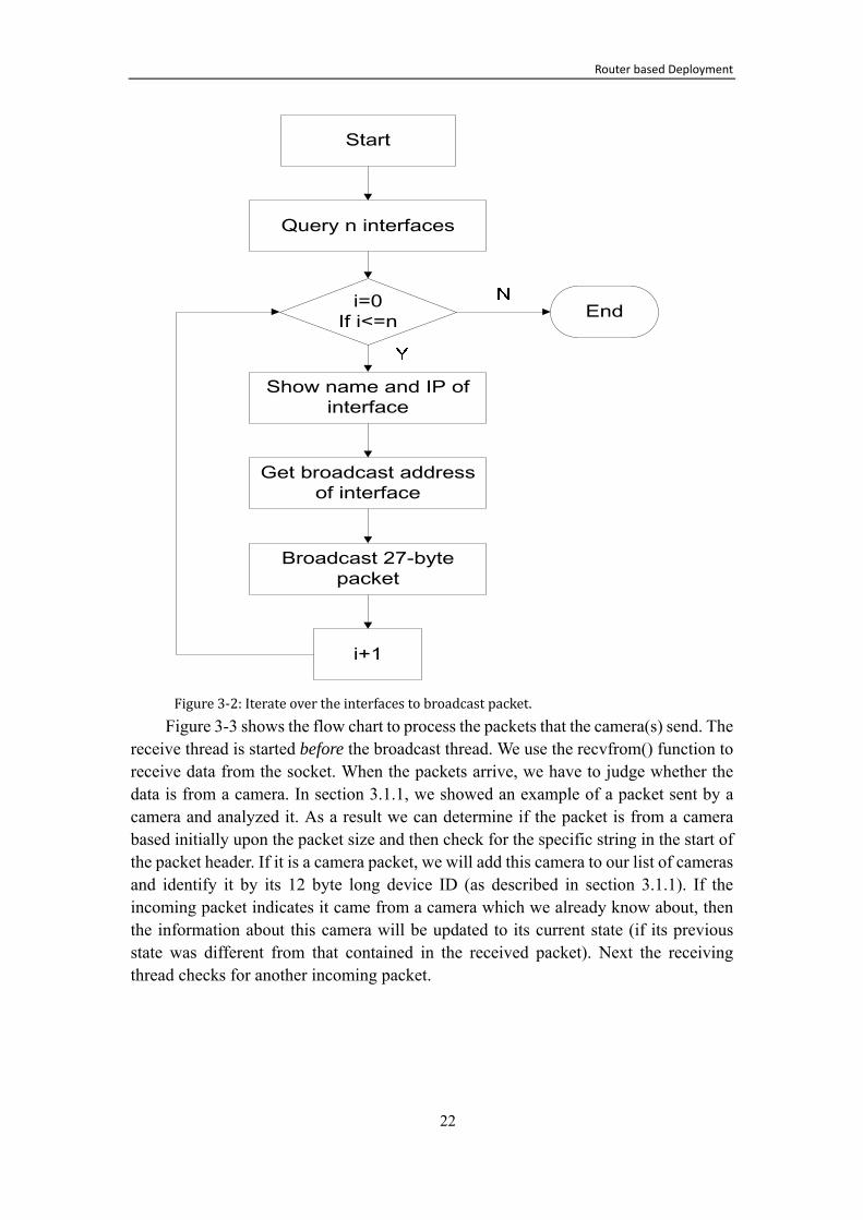
Figure 3-1: Main software development process Since there is more than one interface on the router, we have to list all the local
interfaces, and broadcast the camera discovery packet on the broadcast address of every interface. To do this we design the software to iterate over the interfaces as shown in Figure 3-2.
Router based Deployment
22
Figure 3-2: Iterate over the interfaces to broadcast packet. Figure 3-3 shows the flow chart to process the packets that the camera(s) send. The
receive thread is started before the broadcast thread. We use the recvfrom() function to receive data from the socket. When the packets arrive, we have to judge whether the data is from a camera. In section 3.1.1, we showed an example of a packet sent by a camera and analyzed it. As a result we can determine if the packet is from a camera based initially upon the packet size and then check for the specific string in the start of the packet header. If it is a camera packet, we will add this camera to our list of cameras and identify it by its 12 byte long device ID (as described in section 3.1.1). If the incoming packet indicates it came from a camera which we already know about, then the information about this camera will be updated to its current state (if its previous state was different from that contained in the received packet). Next the receiving thread checks for another incoming packet.

Router based Deployment
23
Figure 3-3:Incoming data processing on router 3.2 Allocating an IP address for a camera
Gardio system is a remote monitor system based on use of an IP network. In large houses there may be more than one router, with each router responsible for several nearby cameras. The local communication interface of Gardio is Wi-Fi, and each camera can only associate with one router that is within range (In this thesis we will not address the question of which router a given camera should associate with when multiple routers are within range.). Moreover, each router will only connect to a certain number cameras because of the images that will need to be processed per unit time will increase with the number of cameras that the router is communicating with. If there are

Router based Deployment
24
too many cameras trying to communicate with a single router at the same time, then the router may not be able perform all of the required computations in real time, hence the system will not work correctly. Note that the Gardio system is not designed to be a large-scale system, but rather is designed based on the typical requirements for a home style surveillance system – rather than a system designed for an industrial or commercial site.
As we discussed in section 2.1.3, IPv6 has a number of advantages over IPv4. The most significant advantage compared to IPv4 is the large IP addresses space. Unfortunately, during the implement of the Gardio system, we found that the Edimax 3G-6210[25] router only supports IPv4. Therefore, we could only use IPv4. Fortunately, the router already has a DHCP module to assign IP addresses hence it can successfully assign IP address for the Gardio system.
3.3 Camera Information Management
After building the communication platform on router, the cameras can be recognized by the router platform, and application will list all the cameras that have connected to router. In order to manage these cameras, we need to provide some useful information about the cameras via the user interface.
This management software is designed to support the user’s needs. The software helps the user to check the status of every camera in the Gardio system. This software is implemented and deployed on the router. In response to queries from the user the software provides a response via the user interface.
Since the Gardio system is a home surveillance system, users may set up cameras in different positions to monitor specific rooms or locations. Therefore, knowing the exact position of each camera is very convenient for users. Given this requirement, we designed the software on router platform to allow the user to name the cameras. When a user receives the Gardio system, the user should initially install the router, and then place the cameras where they are needed. These cameras should be installed one by one, when the camera first connects to the router, then the user will see this camera added to the list of cameras that are on-line. If the system works correctly, the first working camera will automatically be named camera1, and the next cameras that connect to router will be named camera2, camera3, camera4……and so on. Users can change the cameras’ names individually rather than using the automatically assigned names, for example, the cameras might be named: kitchen, Jenny’s bedroom, and living room.
One of the important functions of the Gardio product is face identification. When human beings appear in the camera, or the person moves in the front of camera, the system will generate an alarm and attempt to recognize the person.
The software is also designed to provide status information about each of the cameras. If a camera is suddenly offline, it will appear in the “offline” list. This information helps user to find undesired cameras quickly, as well as to discover

Router based Deployment
25
cameras that have problems as soon as possible. The Gardio system will also give users notifications that the cameras are offline (when requested). For example, a user leaves his house with some cameras working to provide home security; he can mark these cameras so that if their status changes to offline, he will receive a notification.
The status information about each camera includes its IP address, name, current status, previous status, and when the camera image was last checked by the user. All of these records can be stored in servers in order to provide users with more detailed information. Each camera’s information is stored as a node of a linked list, named MyCameraIPs. This information is periodically written to the router’s flash memory and the in core copy is initialized from the flash copy when the router is power on. The time between list updates can be specified. This can be used to provide a comprehensive management platform for the cameras.

Network Security Solution
26
4 Network Security Solution
The first development step in creating the Gardio system is making sure the basic functions of surveillance system work well, and that the router platform is successfully running all the expected functions. In the first step, we use Foscom IP camera to do the experiment. In order to save cost, we are going to design a camera ourselves in the next step. Moreover, we can implement on cameras and add some special function that we need. It is more convenient and flexible for Gardio system development. We will design the hardware and software of camera based on the requirements of Gardio system.
The security of a whole surveillance system is a complicated problem. We should consider the security of media stream, user authentication by remote servers, authentication of cameras, and so on. Many surveillance systems have increased security by using user access control of these servers, in order to control the access to the cameras. This solution is not necessarily safe if the user name, pin code, and other information being communicated to the servers is not properly privacy protected, as the security of whole surveillance system would be destroyed. Recently peer-to-peer authentication has been applied in surveillance systems. In this thesis, we will focus only on the security of communication between the router and the camera(s).
In section 2.2, we described some of the basic network security issues and some of the security solutions that have been adopted in related areas. Based upon this work we propose in this chapter a solution for the security of the Gardio system. Specifically we look to the security of WSNs and security for Voice over IP systems to identify the protocols which we think are the most suitable for providing security for communication between the router and the cameras in the Gardio system. In the final section of this chapter we will also show that these protocols can be implemented on both the router and cameras.
4.1 Security goals and challenges
In section Error! Reference source not found. we explicitly introduce the security requirements of this thesis project. As per our earlier discussion, these security requirements include two parts: communication security and information security. Communication security is a precondition for information security. Communications security enables the nodes to successfully communicate, while preventing attackers from injecting false information into the communications channel. In contrast, information security focuses on the completeness, confidentiality, and timeliness of the information transmitted. Information security is vital for user applications concerning security and monitoring in the context of a home.
In a typical surveillance system, the cameras are responsible for video collection, coding, encryption, and transmission. The remote servers will decrypt and authenticate the media stream. However in this thesis, we deploy the analysis software on the router.

Network Security Solution
27
As noted earlier, this is because the traffic from the cameras would be transmitted to the router in any case and by doing some of the processing at the router we can reduce the amount of traffic that has to be set out of the home. Therefore, the router has to implement both these image analysis functions and do its part to secure the communication to/from the camera.
Initially we will focus on communication security as we want to ensure that only the homeowner’s cameras and router participate in the communications channel. For example, only the homeowner’s own cameras should be able to connect to the network, thus we must make sure that no neighbor’s cameras or router can join our network. Therefore, we consider methods for authentication and authorization, in order to ensure that only authorized nodes can be part of the home’s surveillance network. Additionally, we want to ensure that packets are transmitted safely to their correct destination within our network without their confidentiality being compromised or the packets being modified or destroyed. Therefore we will examine ways to ensure confidentiality and provide retransmission for packets which are not delivered in a timely fashion.
One of the most important challenges that we will face is the problem of authenticating devices that can be dynamically added to a wireless communication network. It is important to minimize the amount of human interaction that is necessary to securely introduce a device to the network; otherwise users will disable the security!
However, some of the challenges that have to be addressed differ from those of traditional WSNs. Specifically since we are considering cameras and routers these devices will need to have mains power (i.e., they will not be battery powered and therefore will not be constrained in terms of their power consumption as typical WSN nodes might be). Additionally, these devices will typically have much more local storage and processing power than traditional WSN nodes. All of these differences enable the use of techniques which might not be suitable for a WSN.
4.2 SRTP
After researching network security protocols, we choose the Secure Real-time Transport Protocol (SRTP) to provide authentication, confidentiality, and integrity for traffic in the Gardio system. Picking a protocol that is associated with secure media transfer seems particularly appropriate as we focus on the security of communications between the cameras and router, and there will be a video stream transmitted from cameras to router. This is quite different from the typical data produced in the context of a WSN, hence we believe that we have adopted a suitable protocol that best fits the needs of our system.
4.2.1 Introduction to SRTP/RTP
The Secure Real-time Transport Protocol (SRTP) is an extension to the Real-time Transport Protocol (RTP). SRTP provides security to RTP traffic, and defines both
Network Security Solution
28
message authentication and integrity protection mechanisms. IETF developed SRTP to enhance the security of RTP. [16]
RTP is designed to transport a multi-media data stream [15]. RTP generally utilizes UDP as its transport protocol. The RTP protocol is composed of a RTP data transfer protocol (RTP) and the RTP control protocol (RTCP). The RTP data transfer protocol is in charge of the transmission of multi-media data, while RTCP is responsible for quality of service, media synchronization, congestion control, and so on. RTP and RTCP are two independent protocols, but usually they are used together.
SRTP provides message authentication, integrity protection, and anti-replay attacks. SRTP also has two parts (SRTP and SRTCP) corresponding to RTP’s RTP data transfer protocol and RTCP. SRTP utilizes AES algorithms to provide the security of RTP/RTCP packets, and uses HMAC-SHA1 algorithms to ensure integrity, message authentication and replay protection. SRTP provides security to the RTP data by encrypting the message using an encryption algorithm (such as AES-CM (by default), AES-f8, or some other mutually agreed encryption algorithm). The encryption can be implemented in hardware or software. It should be noted that many processors are including subsystems to facilitate implementation of these encryption algorithms. Note that encrypting RTP packets does not consume additional bandwidth, however authentication increases the bandwidth used by 4 additional bytes per SRTP packet. The low overhead of SRTP enables high throughput with limited increase required bandwidth.
4.2.2 Format of SRTP/SRTCP Packets
The format of SRTP is almost the same for RTP packets. In addition to the fields of RTP packets, SRTP packets also have an optional Master Key Identifier (MKI) and Authentication Tag.
Figure 4-1 illustrates the format of an SRTP packet. The dark part is the SRTP header, the red part is the payload, and it is the part that needs to be encrypted. Messages have to be authenticated include the SRTP header and payload parts when calculating the Message Authentication Code. This Message Authentication Code will the transmitted in the authentication tag. The blue part of the packet format shows the increased bytes that need to be transmitted with SRTP that would not be transmitted with RTP alone.
The MKI (Master Key Identifier) is defined, signaled, and utilized by the key management protocol. The session keys are derived from a master key. Additionally, the MKI may be used for the purposes of re-keying, so that even if a very large amount of traffic is transmitted the same encryption will not be applied to the same data.
The authentication tag is used to carry message authentication code. The authentication tag provides authentication of the RTP header and payload, and protects against replay attacks by authenticating the sequence number.[16] In a wireless environment the use of an authentication tag increase the required bandwidth. While

Network Security Solution
29
the length of the authentication code can be reduced by using the key management protocol, a shorter authentication code may reduce security and the additional bytes per packet are not of practical significance in a typical WLAN.
0 8 16 31 V=2 P X CC M PT Sequence number timestamp Synchronization source (SSRC) identifier Contribution source (CSRC) identifiers
RTP extension (OPTIONAL)
Payload …
RTP padding RTP pad count
SRTP MKI (OPTIONAL) Authentication tag (RECOMMENDED) Figure 4-1: An example of the format of a SRTP packet [16]
Figure 4-2 illustrates the format of a SRTCP packet. Compared to RTCP, SRTCP adds four new blocks: SRTCP index, SRTCP MKI, authentication tag, and E-flag. The SRTCP MKI is optional. The authentication tag is mandatory in SRTCP in order to ensure message integrity – which is important since SRTCP is a control protocol. Similar to SRTP, the encrypted part of the SRTCP packet is the payload part of RTCP. The the whole RTCP packet (encrypted payload), E-flat, and SRTCP index are included in the authentication.
0 8 16 31 V=2 P RC PT=SR or RR length SSRC of sender Sender info Report block 1 Report block 2 … SSRC/CSRC_1 SDES items … E SRTCP index SRTCP MKI (OPTINAL) Authentication tag Figure 4-2: An example of the format of a Secure RTCP packet [16]
In Figure 4-2, the dark area is the SRTCP header, the red field is the encrypted part. All of the packet should be authenticated except the MKI and authentication tag. The authentication tag is used to carry the authentication results. Before sending the first

Network Security Solution
30
SRTCP packet, the SRTCP index must be 0, and this index will be increased (by 1) as packets are sent. However, when the re-keying mechanism is applied, the index cannot be reset to 0. E-flat indicates whether the current SRTCP packet is encrypted. The functions of MKI and authentication tag in SRTCP are similar to those in SRTP.
4.2.3 Keys and Parameters of SRTP
In SRTP/SRTCP, there are different types of keys: session keys, master keys, and master salt keys. The master key is a random bit string of various lengths (determined by the key management protocol) which must be random and kept secret [16]. The master key is used to generate session keys. Session keys are utilized for message authentication and encryption. The salt is the input parameter used when generating session keys. The master salt key is used in the key derivation procedure to produce session keys. Master keys and master salt keys are established by an external key management mechanism (such as MIKEY – see section 4.3 on page 33). The key derivation functions will calculate session keys for authentication and encryption. Figure 4-3 describes the key derivation in SRTP.
Figure 4-3: SRTP keys derivation A cryptographic context is the cryptographic state information that the SRTP
sender and receiver set up for each session. The cryptographic context should be identified based upon the synchronization source (SSRC), destination network addresses, and destination transport port number. There are two types of parameters in a cryptographic context: Transform-independent parameters and transform-dependent parameters. Transform-dependent parameters are some parameters about encryption, authentication and key derivation, such as block size of ciphers, session keys, data for the Initialization Vector (IV) formation, etc. [16] Details of the significant transform-independent parameters are introduced below.
A 32-bit unsigned rollover counter (ROC) records how many times the RTP sequence number (SEQ) has been reset to zero when it reaches at 65535. SEQ is extracted from the RTP packet header. The SRTP index is calculated as i 2
. A 16-bit sequence number is used to record the highest RTP sequence number. It is recommended that the sequence number field be authenticated. When authentication and replay protection are provided, a replay list is needed to record the

Network Security Solution
31
index of recently receiving authenticated SRTP packets. The MKI indicator (0/1) defines whether MKI is present in SRTP and SRTCP packets. The key_derivation_rate is the rate of session keys derivation, range of values is 1- 224. SRTP and SRTCP by default share most of the parameters in the cryptographic context.
4.2.4 Replay Protection
Replay attacks may exist in any network communication. In such an attack the attacker sends packets which have already been received by the host. These attacks usually occur against the identity authentication process. Attackers forge authentication information using information derived from network sniffing, and then send these packets to servers. While encryption can prevent session hijacking, it fails to avoid replay attacks.[30]
Replay protection can be used only when integrity protection is present. When message authentication is used in SRTP, the receiver can prevent replay attacks by maintaining a replay list. The replay list includes the packet index of packets which has been received and authenticated. The receiver use realizes replay protection by using a “sliding window”. The size of this sliding window is at least 64 entries. The receiver checks the index and looks at packets in the window when there is an incoming packet. Packets can be accepted when the packet index is ahead of the window or inside the window but was not received before.[16]
4.2.5 Security Algorithms in SRTP/SRTCP
SRTP allows the two communicating parties to determine their choice of cryptographic algorithms and authentication algorithms; however, there are some default algorithms that must be implemented.
The default encrypting/decrypting algorithm for RTP payloads is AES (Advanced Encryption Standard). SRTP supports three modes in encryption: AES-CTR [31], NULL, and AES-f8. SRTP can choose not to encrypt the RTP payload if the underlying network security is sufficient for the system. AES-CTR and NULL are mandatory to implement.
Message integrity is validated through the SRTP authentication tag. First, the sender will calculate message authentication code, add it to the end of packet, and then send it. The receiver calculates a new message authentication code according to the agreed algorithms and keys, and compares it with the message authentication code which has just been received. If the two message authentication codes are same, then the packet is considered to be authentic. Otherwise, the packet cannot be accepted, and the receiver will send an “authentication failure” indication. There is a difference between SRTP and SRTCP with respect to message authentication. SRTCP only needs to authenticate the packet, but ROC is also need to for the authenticated of SRTP. By default in SRTP the authentication algorithm is HMAC-SHA1 [32], and it is mandatory to implement. Table 4-1 describes the algorithms used for different purposes in

Network Security Solution
32
SRTP/SRTCP. Table 4-1: mandatory to implement, optional and default transforms in SRTP and SRTCP [16] Mandatory to
implement Optional Default
Encryption AES-CM, NULL AES-f8 AES-CM
Message integrity HMAC-SHA1 - HMAC-SHA1
Key derivation AES-CM - AES-CM
4.2.6 SRTP Packet Processing
The SRP sender establishes a master key and master salt using a key management protocol. The next step is to determine session key and session salt according to the parameters such as master key, master salt, key_derivation_rate, session key-lengths in cryptographic context and the index which has been calculated. The derivation process can be described in the following functions:
key_session = PRF (key_master, x); r = index/key_derivation_rate; key_id = <label> || r; x = key_id XOR master salt; PRF is the symmetrical encryption function of AES-CM.
After determining the session key, the next task is to select the cryptographic context that is to be used and to encrypt the RTP payload using the agreed upon encryption algorithm in the cryptographic context, session encryption key, and session salt. When the MKI indicator is set to one, it should be appended to the SRTP packet. Finally, an authentication tag is calculated and added to the packet, and the ROC and index are updated (as necessary).
In order to authenticate and decrypt the SRTP packet the SRTP receiver determines the cryptographic context, and calculates the SRTP index. If MKI is set to 1, we can determine the master key and master salt based upon the MKI. Otherwise, we use the index to determine the relevant master key and master salt. The session key is derived just as in the sender process. The next step is message authentication and replay protection. Use the replay list and index to check if the packet has been replayed. If this is a replay, then the packet must be discarded and the event should be logged. The authentication tag is verified using the ROC and authentication algorithm, the detailed process was introduced in section 4.2.5. If the result is “authentication failure”, then the packet has to be discarded and the event should be logged. The packet payload is decrypted using the session key. After accepting the packet the parameters such as ROC, highest sequence number, sl and replay list should be updated. Last but not least, the MKI and authentication tag are removed from packet.

Network Security Solution
33
4.3 MIKEY
The communicating parties need to establish a series of parameters (such as the choice of encryption algorithm and authentication algorithm for SRTP). Meanwhile, the parties need to establish one or more session keys to encrypt the packets in the conversation. Additionally, another session key may be needed for authentication. The same sorts of session keys are needed for the SRTCP communication. Therefore, how to agree upon these algorithms and how to establish master keys for a session needs to be done before establishing the communications session. This is the function of key management protocol.
Although IETF has already developed some schemes for key management, such as ISAKMP [33] and IKE [34] which are popular for unicast schemes for IPsec, there was a need for a protocol with simpler algorithms and lower latency. The algorithms of ISAKMP were too complicated for real-time data transmission, as they would cause too high a data latency. Therefore, the key management protocol MIKEY (Multi-media Internet Keying) was designed to provide a low cost and low latency means of establishes the required keys and agreements about algorithms. MIKEY ensures the security of peer-to-peer communication – based upon a tunneling mode. MIKEY’s major advantages are high throughput (due to low bandwidth, low cost, and simple computation) and a simple implementation. Since surveillance system need to do data transmission in real-time for a large amount of data, MIKEY is a suitable key management for Gardio. This is especially true as MIKEY was designed to support SRTP.
4.3.1 Overview of MIKEY
MIKEY can be used for peer-to-peer, simple one-to-many, and small-groups. It is designed to support multimedia scenarios. The typical application scenarios are [24]:
1. Peer to peer (unicast): e.g. the SIP [35] calls. Two parties may set up the same security agreement or each part builds its own security scheme for data stream.
2. Simple one to many (multicast): e.g. real-time conference. The sponsorship is responsible for setting up the security.

Network Security Solution
34
Figure 4-4: peer to peer and simple one to many scenarios. 3. Many to many: without a centralized control unit, e.g., the small size
communications groups. There are two models, one is only one group server can authenticate new members. The other one is the authorized rights to include new members can carry out by other participants.
Figure 4-5: many to many without a centralized control unit scenario. 4. Many to many: with a centralized control unit, e.g. some larger groups with a
group server which can set up the security.

Network Security Solution
35
Figure 4-6: many to many with a centralized control unit scenario.
Here we will introduce some technical terms of MIKEY. A Data Security Association (Data SA) is the information needed by the security protocol, including keys and other parameters. The traffic-encryption Key (TEK) is used to protect encrypted sessions directly by security protocol or based upon other keys. The TEK Generation Key (TGK) is usually a random string. The TEK can be generated by using TGK, without other communications. A Crypto Session (CS) is the data stream that is encrypted by the security protocol. For example, when the SRTP is used, a CS always includes a RTP stream and a RTCP stream. One CS has a unique CS ID. A Crypto Session Bundle (CSB) is composed of several CSs. The CSB has the same TGK and security parameters. One CSB has the only a single CSB ID.
The aim of MIKEY is to generate a data SA including TEK and other parameters for use by a security protocol. MIKEY supports setting up keys and parameters for multiple security protocols. A CSB is applied to one or more crypto sessions, these sessions have the same TGK and security parameters, but different TEK. Figure 4-7 describes the procedure of establishing CBS, TEK and data SA. Some security parameters and TGK are generated by consensus according to the CSB. The TEK for the crypto session is obtained from the TGK by encryption. The Data SA is described by a TEK and security protocol parameters, and it is the input to the security protocol. The security protocol can use the TEK directly or can calculate session keys (such as used in SRTP) based upon the TEK. The use of TEK depends on the implementation of the specific security protocols.

Network Security Solution
36
Figure 4-7: Overview of MIKEY key management procedure. [24] 4.3.2 Methods of Key Transport and
Exchange
MIKEY has three different methods to transport/establish a TGK, they are: pre-shared key, public key encryption, and Diffie-Hellman (DH) key exchange. [24] In order to derive a TEK, there should be another random nonce RAND in addition to the TGK. RAND and TEK are used in all three cases. A timestamp is also used to avoid replay attacks. Both the pre-shared key method and public key method are based on key transport mechanisms, and they are both mandatory to implement, whereas the DH method is optional. In the DH method the TGK is derived from DH values exchanged between the peers.
In general, the pre-shared key method is the most efficient method, and it uses the least resources as compared to other two methods. The pre-shared key method use symmetric cryptography and only a small amount of data will be exchanged using this method. However, this approach has a problem of sharing individual keys in a large group with many peers. Therefore, it is mainly used for server-to–client scenarios. [24] Compared to the pre-shared key method, the public-key method has two disadvantages. It consumes more resource, and it needs a public key infrastructure (PKI) to provide public key distribution. The DH method is more secure and flexible, but it costs the most resources (both in terms of computation and bandwidth) as compared to the two methods above.

Network Security Solution
37
4.3.2.1 Pre-shared key
Figure 4-8: MIKEY packet format in pre-shared key mode. [24] The pre-shared symmetric key is used to derive key material for encryption
(encr_key) and the integrity protection (auth_key) of a MIKEY message. The aim of the initiator message is to transport one or more TGKs and a set of security parameters to the responder in a secure way. The initiator will describe in the HDR if it asks for a verification message from the responder. The KEMAC is computed as:
KEMAC = E(encr_key, {TGK}) || MAC The KEMAC contains a set of encrypted sub-payloads and a message
authentication code. Note that each sub-payload has a random TGK. The message authentication code is the message authentication code of the MIKEY message computing using auth_key. The responder sends a verification message in order to authenticate each itself to the other party. It computes a message authentication code over a timestamp and the IDs of two parties using authentication key. The timestamp is used is the same as used by the initiator.
4.3.2.2 Public-key encryption
Figure 4-9: MIKEY packet format in public-key encryption.[24] The objective of the initiator is the same as in the pre-shared key method. It is
realized by using an envelope approach. The TGK is encrypted using keys from a random/pseudo random envelope key (env_key). The calculation of PKE is PKE=E(PKr, env_key); thus it includes the envelope key and the public key of

Network Security Solution
38
responder. The KEMAC is computed according to:
KEMAC = E(encr_key, IDi || {TGK}) || MAC The same to pre-shared key, KEMAC also contains a set of encrypted
sub-payloads and a message authentication code. IDi in the KEMAC is the identity of the Initiator. The encryption key and authentication key are derived from the envelope key. The SIGNi is a signature covering the entire MIKEY message, using the Initiator's signature key [24]. The verification message is calculated and used in the same way in pre-shared key mode.
4.3.2.3 Diffie-Hellman (DH) key exchange
Figure 4-10: MIKEY packet format in DH key exchange mode.[24]
This method generates a DH key. The DH key can be used as a TGK. It can only be used to generate peer-to-peer keys. It is optional to implement. Other parameters are introduced in MIKEY see RFC 3830 [24]. This approach does not need to exchange certificates in advance, and both parties affect the generation of TGK which makes this mode more secure.
4.3.3 Key Calculation for MIKEY
The calculation in MIKEY can be divided into two parts: (1) TGK is used to derive TEK and encryption key, authentication key and salt key of the security protocol and (2) the encryption key, authentication key and salt key of MIKEY message are generated from an envelope/pre-shared key. The parameters and key derivation functions are introduced in [24].
Table 4-2 shows the constant values used when deriving keys from a TGK. The label is a parameter used when generating keys. Label= constant || cs_id || csb_id || RAND. Different types of keys utilize different constant values to generate these keys. For example, the constant 0x2AD01C64 is used to generate a TEK from a TGK.

Network Security Solution
39
Table 4-2: Constant values for the derivation of keys from TGK.[24] constant Derived key from TGK 0x2AD01C64 TEK 0x1B5C7973 Authentication key 0x15798CEF Encryption key 0x39A2C14B Salt key
Table 4-3 shows the constant values used when generating keys from an envelope/pre-shared key. The calculation function of label is:
label= constant || 0xFF || csb_id || RAND. Table 4-3: Constant values for the derivation of keys from an envelope/pre-shared key.[24]
constant Derived key 0x150533E1 Encryption key 0x2D22AC75 Authentication key 0x29B88916 Salt key
4.3.4 Pre-defined algorithms
The default transform is mandatory to implement in MIKEY. MIKEY defines a set of security algorithms and key length as defaults. The AES algorithm (128-bit) is used to encrypt packet payloads and HMAC-SHA1 (160-bit) is used to authenticate messages. It is mandatory to implement SHA-1 as the default hash function. The size of the hash function’s output is equal to the size of authentication key. The NULL encryption algorithm is optional.
The envelope key encryption algorithm and digital signature algorithm depend on the use of a certificate. The mandatory security algorithm is RSA.
4.4 Implementation
We have introduced SRTP and MIKEY in sections 4.2 and 4.3. According to the network security requirements we discussed in section 4.1, SRTP and MIKEY could provide good network security for the data stream, and they mainly satisfy the requirements of the Gardio system.
In this section, we will focus on the implementation of SRTP and MIKEY according to the platform environments of the router and the camera. We will also consider the related problems that we have to take into account in order to provide a suitable solution for the Gardio system.
4.4.1 Design of SRTP Modules
The implementation of SRTP is mainly designed based on Ericsson SRTP source code. It has been successfully implemented on a Linux system. The source code of
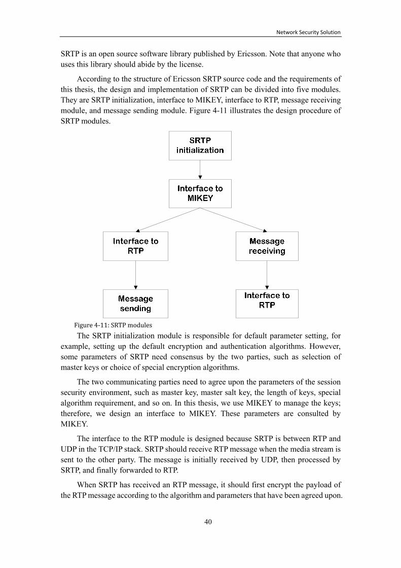
Network Security Solution
40
SRTP is an open source software library published by Ericsson. Note that anyone who uses this library should abide by the license.
According to the structure of Ericsson SRTP source code and the requirements of this thesis, the design and implementation of SRTP can be divided into five modules. They are SRTP initialization, interface to MIKEY, interface to RTP, message receiving module, and message sending module. Figure 4-11 illustrates the design procedure of SRTP modules.
Figure 4-11: SRTP modules The SRTP initialization module is responsible for default parameter setting, for
example, setting up the default encryption and authentication algorithms. However, some parameters of SRTP need consensus by the two parties, such as selection of master keys or choice of special encryption algorithms.
The two communicating parties need to agree upon the parameters of the session security environment, such as master key, master salt key, the length of keys, special algorithm requirement, and so on. In this thesis, we use MIKEY to manage the keys; therefore, we design an interface to MIKEY. These parameters are consulted by MIKEY.
The interface to the RTP module is designed because SRTP is between RTP and UDP in the TCP/IP stack. SRTP should receive RTP message when the media stream is sent to the other party. The message is initially received by UDP, then processed by SRTP, and finally forwarded to RTP.
When SRTP has received an RTP message, it should first encrypt the payload of the RTP message according to the algorithm and parameters that have been agreed upon.

Network Security Solution
41
Secondly, it must calculate the SRTP authentication tag and add it to the end of message, if there integrity protection is desired. Finally, the SRTP message is sent using a UDP socket. This completes the implementation of the SRTP message sending module.
The fifth module is the SRTP message receiving module. Initially an SRTP message is received by a UDP socket. If there is integrity protection, then the receiver calculates the authentication tag of message, and compares it to the original authentication tag that was added to the end of the receiving message. If they are same, the receiver decrypts the payload of the message, and forwards the message to RTP. Otherwise, it rejects the message and returns a authentication error indication.
4.4.2 Design of MIKEY Modules
The implementation of MIKEY is mainly designed based on Ericsson MIKEY source code. It has been successfully implemented on a Linux system. The source code of MIKEY is an open source software library published by Ericsson. However, anyone who uses this library should abide by the license.
The MIKEY module design is according to Ericsson MIKEY library and RFC 3830 [24]. The design of MIKEY can be divided into seven modules.
1. MIKEY initialization module: This module is responsible for the initialization work of MIKEY, such as setting up new users’ information
2. CSB module: A new CSB is set up in this module; it includes the initialization of CSB default parameters. Such as default random number generator, encryption algorithms, authentication algorithm, random CSB ID, TGKs and a random salt key. The default parameters will be used directly if there is not a special requirement of the communication two parties. When a host receives a new communication request, this module should be performed immediately.
3. Message of initiator module: Every field of the initiator’s message is constructed based on the message of MIKEY pre-shared transport. The message includes header, timestamp, random number (acquired from CSB initialization), ID of initiator and responsor, and KEMAC.
4. Message of responsor module: This module is used to build the message of MIKEY responsor, including protocol header, timestamp, ID of responsor, and authentication tag.
5. Initiator’s message analysis module: When responsor receives the message from initiator, it will analyze the message. The analysis includes two steps; the first step is timestamp verification of the message. The other step is comparing Message Authentication Code as introduced in section 4.4.1.
6. Responsor’s message analysis module: The Initiator uses this module to analyze the message from the responsor. The working

Network Security Solution
42
procedure is the same as initiator’s message analysis module. It mainly focuses on the timestamp and Message Authentication Code value of the message.
7. Base64 module: According to RFC3830 [24], the MIKEY message should be transported using Base64 coding format. Therefore, MIKEY message should perform Base64 encoding before sending. In the same manner, the MIKEY message should be decoded first after receiving.
MIKEY works in the following two modes: initiator mode and responsor mode. They have different processing flow. The following figure shows the flow chart of two modes based on MIKEY modules.

Network Security Solution
43
Figure 4-12: flow chart of MIKEY message processing

Network Security Solution
44
4.4.3 Security Algorithm Implementation
There are some sub-modules of SRTP and MIKEY that should be implemented. They are the security algorithm modules.
There are three security algorithms have to be implemented in SRTP, they are AES-f8 module, AES-CM module and HMAC-SHA1 module. The original design of AES in SRTP is using Rijindael to calculate by C code. Eriksson SRTP uses API function provided by OpenSSL library to realize HMAC-SHA1 algorithm.
In MIKEY, the algorithms AES-CTR, SHA-1, HMAC-SHA1, and RSA need to be implemented. Ericsson MIKEY uses Rijndael to calculate AES encryption/decryption. Use OpenSSL library to realize SHA-1, RSA and HMAC-SHA1.
Moreover, we can choose to use a hardware implementation using a hardware security module if it is available. The calculation speed is sometimes faster than a software implementation. For example, a Symmetric Key Hardware Accelerator can realize the symmetric encryption algorithms AES and DES (which are widely used). A Message Digest Hardware Accelerator can realize algorithms such as SHA1 and MD5. Finally a hardware Random Generator can be used to generate random numbers, as the are frequently used in SRTP and MIKEY.

Analysis
45
5 Analysis
We have successfully developed the router platform as described in section 1.2.4. The router platform can receive data from cameras using a socket receive function. The router will continually receive the same data from one camera until the receive thread is finished or until the image from the camera changes. In order to solve this problem, we ignore the same data which we have already received. Additionally for testing purposes we limited the time during which the router receives data from the cameras to 20 seconds.
We assume that in practice the largest number of cameras that will connect to one router will be 7-9, with each camera uploading up to 30 frames per second (fps) at a resolution of 320*240 (i.e., VGA resolution). We assume a compression ratio of 10:1. As a result the estimated size of each JPG file is about 7.5 Kbyte; this means that one camera can upload roughly 225 Kbytes per second. This means that the maximum data rate of each camera is about 0.22 MB/s. Therefore, we can estimate that the maximum number of cameras that can connect to one router must be less than 9. The memory consumed by the image processing module in the router is less than roughly 2MB (this size was provided by person who wrote the image analysis software, which described in another master’s thesis [36] ).
We ran three groups of tests with different numbers of cameras. These tests were divided into three groups: the first group (a) includes 3 cameras and the router platform; the second group (b) has 5 cameras; and the third group (c) has 7 cameras. We start the broadcast and receive threads by manually entering the command “scan” in our experimental step. In an actual fielded implementation the broadcast thread might only be sent once per minute (this it would take on average 30 seconds to discover a new camera). Similarly the application getting image data from the cameras could reduce the frame rate to a selected rate. In both cases reducing the rates will reduce the resources used.
Table 5-1 lists the results of these tests. The receive thread starts before broadcast is sent and ends after the broadcast thread is over The broadcast thread runs for 20 seconds. After the broadcast thread starts, the data which the router platform receives the first time from each camera will be registered. We list the time when the data from the last camera of each group is received. From the table, we can conclude that the time increases as the number of cameras increases. However, mostly of the time the response time is around 6-8 seconds. In order to make sure all the data from cameras can be received within the thread time, we limited the broadcast thread to run for 20 seconds. This was sufficient to concurrently service a group with eight cameras.

Analysis
46
Table 5-1: The longest time to receive data from the cameras Time
Group
1 2 3 4 5 6 7 8 9 10
a 6.2s 4.9s 5.3s 5.0s 5.3s 4.8s 4.3s 5.5s 5.0s 5.9s
b 8.7s 7.9s 8.8s 6.5s 5.4s 6.0s 6.9s 7.0s 8.1s 7.2s
c 10.1s 9.7s 8.2s 7.7s 8.9s 8.7s 7.4s 6.5s 6.2s 8.1s
Table 5-2 is the analysis of the data calculated by using Microsoft’s Excel application. This table shows the minimum time, maximum time, average time, and standard deviation of the three groups. Generally, the receiving time increases as the number of cameras increases (which we can see from the median values). The standard derivation also increases as the number of cameras increases. Therefore, there seems to be a connection between the number of camera and the time to receive data from cameras, but we are not yet sure of exactly what this relationship is. We can conclude that, the more cameras there are, the long the receiving time is. The most probably reason might be contention for sending network traffic to the router. Although it is obvious that the receive thread will take longer when the number of cameras increases and the time to receive data from all the cameras in the group will also increase with the number of cameras (as they have to share the same network capacity). When cameras receive the broadcast message which is sent by router platform, each camera might response with multiple packets, the router will receive a packet via the socket and add this camera to list of cameras whose data it must process. The increasing number of cameras increases the number of data packets that are sent to the socket, hence the router has to receive and service more packets proportional to the number of cameras and their frame rates and resolutions. Table 5-2: Analysis of the results
Minimum Maximum Median Standard deviation
a 4.3s 6.2s 5.2s 0.6s
b 5.4s 8.8s 7.1s 1.1s
c 6.2s 10.1s 8.2s 1.3s
Figure 5-1 shows a plot of the data from the three groups of experiment. We can see from the figure, the general trend lines of these three groups gradually decline. The longest time of one group mostly appears in the first time that the test was run for this configuration. The reason for this might be the extra time needed to add each new camera to the list of cameras. There are also some lower points in the groups. Most of the lower points of the three groups are around 6 seconds. We could simply conclude
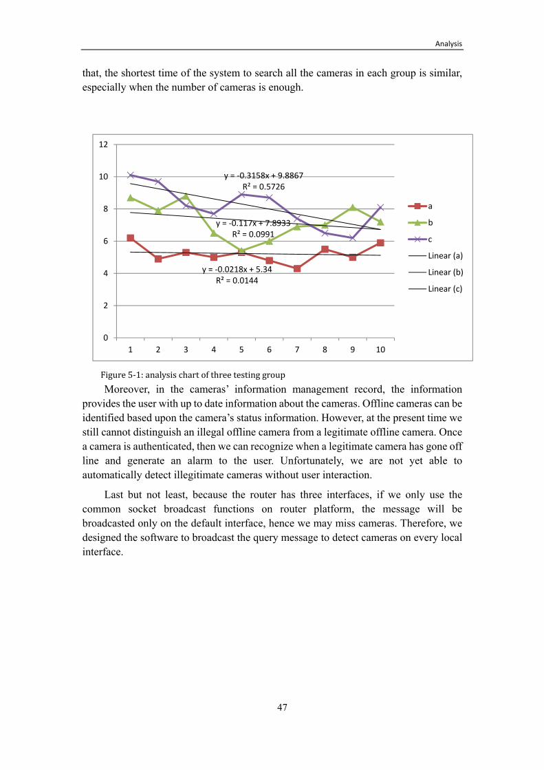
Analysis
47
that, the shortest time of the system to search all the cameras in each group is similar, especially when the number of cameras is enough.
Figure 5-1: analysis chart of three testing group Moreover, in the cameras’ information management record, the information
provides the user with up to date information about the cameras. Offline cameras can be identified based upon the camera’s status information. However, at the present time we still cannot distinguish an illegal offline camera from a legitimate offline camera. Once a camera is authenticated, then we can recognize when a legitimate camera has gone off line and generate an alarm to the user. Unfortunately, we are not yet able to automatically detect illegitimate cameras without user interaction.
Last but not least, because the router has three interfaces, if we only use the common socket broadcast functions on router platform, the message will be broadcasted only on the default interface, hence we may miss cameras. Therefore, we designed the software to broadcast the query message to detect cameras on every local interface.
y = -0.0218x + 5.34R² = 0.0144
y = -0.117x + 7.8933R² = 0.0991
y = -0.3158x + 9.8867R² = 0.5726
0
2
4
6
8
10
12
1 2 3 4 5 6 7 8 9 10
a
b
c
Linear (a)
Linear (b)
Linear (c)

Conclusion and Future Work
48
6 Conclusions and Future Work
In this thesis, we mainly focus on the primary development of a home surveillance system. We successfully finished the thesis works which are discussed in 1.2.4. We developed the router platform in order to make the router search and management the cameras. Since the network communication need a secure mechanism, we also discussed about network security protocols and algorithms, and then find a suitable solution for this thesis system.
The first aspect of research concerns the design, implementation, and the deployment of additional software on the router platform. This software is similar in function to the Windows based IP camera tools. Therefore, we discussed the working process of IP camera tools in section 2.1.1. In order to configure cameras in a more secure and easy way, we introduced the internet configuration method in section 2.1.2, and then compare the IPv4 and IPv6 in section 2.1.3 in order to choose a better solution for this surveillance system.
This software looks for new cameras being attached to the LAN and can analyze images from these cameras. This software also provides security and management information for the users. We described how we have set up a secure communication channel between the cameras and the Linux router in section 3.1. Next, in section 3.3, we design an information management scheme for the cameras which are connected to the router.
The other aspect of research concerns the network security necessary for a home surveillance system. When cameras and router upload the data packets, they should make sure the packets are security and integrity. Therefore, in related work in chapter 2, we firstly discussed security requirements in 2.2.1and security problems in 2.2.2. And then we introduced some related areas about some network security protocols worked for different conditions, the cryptography algorithms and key management protocols.
We designed and implemented a good security solution using SRTP and MIKEY. In chapter 4, we introduced SRTP and MIKEY, and the implementation solutions on top of an embedded Linux system.
In chapter 5, in order to validate the running time of receive thread, we did a test of three group cameras to test the time of receiving all the cameras in the group. There are 3, 5, 7 cameras in the three groups respectively. After analysis of the data of the three groups, we can conclude that in general, the receiving time is gradually increasing as the cameras increase. We also estimate the maximum number of cameras that one router can connect.
The future work involves optimization of the implementation of the network security mechanism in the context of the complete system, and find better solutions to management the camera notes in the system (such as fault tolerant). We also should
Conclusion and Future Work
49
consider adding additional sensors (such as motion detectors) which could make the home surveillance system more intelligent. The aim of our implementation and future optimization is to reduce the cost of both the capital expense of the system and the annual cost of operating the system. Additionally, we are going to design a new camera based on the existing camera, but will incorporate directly into the camera additional security mechanism and data fusion directly in the sensors.


References
51
References
[1] Remi Bosman, Johan Lukkien, and Richard Verhoeven, An integral approach to programming sensor networks, In proceedings of the 6th IEEE Consumer Communications and Networking Conference, 2009.
[2] R. Droms, Dynamic Host Configuration Protocol, Internet Request for Comments, ISSN 2070-1721, RFC 2131, RFC Editor, March 1997, Updated by RFCs 3396, 4361, 5494, http://www.rfc-editor.org/rfc/rfc2131.txt
[3] Cavium Networks Embedded ARM Processors [Online]
http://www.caviumnetworks.com/pdfFiles/CNS1_12XX_PB%20Rev%200.1.pdf
[4] Tony Mancill, Linux Routers: A Primer for Network Administrators, Prentice Hall, 2000, 350 pages, ISBN: 0130861138
[5] R..Hinden and S. Deering, IP Version 6 Addressing Architecture, RFC 4291, RFC Editor, February 2006, Updated by RFCs 5952, 6052, http://tools.ietf.org/html/rfc4291
[6] P. Livis and M. Boucadair, IPv4 Shortage Framework, draft-levis-behave-ipv4-shortage-framework-02.txt, RFC Editor, June 2009, http://tools.ietf.org/html/draft-levis-behave-ipv4-shortage-framework-02
[7] B. Haberman and D. Thaler, Unicast-Prefix-based IPv6 Multicast Addresses, RFC 3306, RFC Editor, August 2002, Updated by 3956,4489, http://tools.ietf.org/html/rfc3306
[8] Yanzhao Xie, The embedded video monitoring system based on IPv6, Master thesis, School of Computer Science, Nanjing University of Aeronautics and Astronautics, January 2008. [online]
http://wenku.baidu.com/view/2fce96116c175f0e7cd13746.html
[9] Su Guangxue and Wang Wendong, A Quick CGA Generation Method, 2010 2nd International Conference on Future Computer and Communication, volume 1, pp. 770-773.
[10] Shu Wang and Yan Yujie, (The theory and applications
of wireless sensor network). Beijing Aeronautics and Astronautics Press, July 2007, 417 pages, ISBN: 9787811242195.
[11] Yong Wang and Gahan Attebury. A Survey of Security Issues in Wireless Sensor Networks, IEEE Communications Surveys & Tutorials • 2nd Quarter 2006.
[12] C. Karlof and D. Wagner, Secure Routing in Wireless Sensor Networks: Attacks and Countermeasures, Proc. First IEEE International Workshop on. Sensor Network Protocols and Applications, May 2003, pp. 113–27.

Conclusion and Future Work
52
[13] H. Chan, A. Perrig, and D. Song, Random Key pre-distribution for Sensor Networks. In proceeding of the IEEE Computer Society Symposium on Security and Privacy. IEEE, Piscataway, NJ, USA, 2003, pp. 197-213.
[14] Charlie Kaufman, Radia Perlman, and Mike Speciner. Network Security: private communication in a public world. Second edition. Prentice Hall, 1995, ISBN 0130614661.
[15] H. Schulzrinne, S. Casner, R. Frederick, and V. Jacobson, RTP: A Transport Protocol for Real-Time Applications, Internet Request for Comments, ISSN 2070-1721, RFC 3550, RFC Editor,July 2003, Updated by RFCs 5506, 5761, http://www.rfc-editor.org/rfc/rfc3550.txt
[16] M. Baugher, D. McGrew, M. Naslund, E. Carrara, and K. Norrman, The Secure Real-time Transport Protocol (SRTP), Internet Request for Comments, ISSN 2070-1721, RFC 3711, RFC Editor, March 2004, Updated by RFC 5506, http://www.rfc-editor.org/rfc/rfc3711.txt
[17] T. Dierks and E. Rescorla, The Transport Layer Security (TLS) Protocol Version 1.2, Internet Request for Comments, ISSN 2070-1721, RFC 5246, RFC Editor, August 2008,Updated by RFCs 5746, 5878, http://www.rfc-editor.org/rfc/rfc5246.txt
[18] R. Stewart, Stream Control Transmission Protocol, Internet Request for Comments, ISSN 2070-1721, RFC 4960, RFC Editor, September 2007, http://www.rfc-editor.org/rfc/rfc4960.txt
[19] Cisco Systems, Inc. Certificate Authority Proxy Function, in Cisco IP Phone Authentication and Encryption for Cisco CallManager 4.0(1), San Jose, CA 95134-1706 USA, 2003, Part Number: OL-5109-01, http://www.cisco.com/en/US/docs/voice ip comm/cucm/security/4 0 1/secucapf.html
[20] Chris Karlof, Naveen Sastry, and David Wagner, TinySec: A Link Layer Security Architecture for Wireless Sensor Networks, Proceedings of the 2nd international conference on Embedded networked sensor systems (SenSys’04), ACM, November 3–5, 2004, Baltimore, Maryland, USA, ISBN:1-58113-879-2, http://www.cs.berkeley.edu/~daw/papers/tinysec-sensys04.pdf
[21] Adrian Perrig, Robert Szewczyk, Victor Wen, David Culler, and J. D. Tygar, SPINS: Security Protocols for Sensor Networks, Department of Electrical Engineering and Computer Sciences, University of California, Berkeley.
[22] N. Gura et al., “Comparing Elliptic Curve Cryptography and RSA on 8-bit CPUs,” CHES '04: Proceedings of the Workshop. Cryptographic Hardware and Embedded Systems, Aug. 2004.

Conclusion and Future Work
53
[23] C. Karlof, N. Sastry, and D. Wagner, “Tinysec: A Link-Layer Security Architecture for Wireless Sensor Networks,” SenSys'04: Proc. 2nd Int'l. Conf. Embedded Networked Sensor Systems, New York: ACM Press, 2004, pp. 162–75.
[24] J. Arkko, E. Carrara, F. Lindholm, M. Naslund, and K. Norrman, MIKEY: Multimedia Internet KEYing, Ericsson Research, RFC 3830, RFC Editor, August 2004, http://tools.ietf.org/html/rfc3830.
[25] EDIMAX Technology Co., Ltd., 3G-6210n Wireless 3G Portable Router with Battery, User’s Manual, Version 1.0, Edimax Technology Co, Ltd., Taipei Hsien, Taiwan. R.O.C., September 2009, 147 pages http://www.edimax.com/images/Image/manual/Wireless/3G-6210n/3G-6210n Manual.zip
[26] Emmanouil Karamanos, Investigation of home router security, Master’s Thesis, School of Information and Communication Technology, Royal Institute of Technology (KTH), Stockholm, Sweden, TRITA-ICT-EX-2010:38, April 2010 http://web.it.kth.se/~maguire/DEGREE-PROJECT-REPORTS/100411-Emmanouil-Karamanos-with-cover.pdf
[27] Ulf Lamping, Richard Sharpe, and Ed Warnicke, Wireshark Network Analyzer - User's Guide, 36347 for Wireshark 1.5, 2011, (last accessed 2011.03.25), http://www.wireshark.org/docs/wsug_html_chunked/
[28] J. Arkko, J. Kempf, B. Zill, and P. Nikander, SEcure Neighbor Discovery (SEND), Internet Request for Comments, ISSN 2070-1721, RFC 3971, RFC Editor, March 2005. http://www.rfc-editor.org/rfc/rfc3971.txt
[29] Télécom SudParis, NDprotector: an implementation of CGA & SEND for GNU/Linux based on Scapy6, 30 June 2010, http://amnesiak.org/NDprotector/
[30] Kent S. and Atkinson R., Security Architecture for Internet Protocol. RFC2401. IETF, November 1998. http://www.rfc-editor.org/rfc/rfc2401.txt
[31] H. Lipmaa, P. Rogaway, and D. Wagner. "Comments to NIST Concerning AES Modes of Operations: CTR-Mode Encryption," First NIST Workshop on Modes of Operation for Symmetric Key Block Ciphers, Oct. 2000.
[32] H. Krawczyk and M. Bellare. HMAC: Key Hashing for message authentication. RFC 2014. IETF, February 1997. http://www.rfc-editor.org/rfc/rfc2104.txt
[33] D.Maughan, M.Schertler, M.Schneider, and J.Turner. Internet Security Association and Key Management Protocol (ISAKMP). RFC 2408. IETF, November 1998. http://tools.ietf.org/html/rfc2408
[34] D. Harkins and D. Carrel, "The Internet Key Exchange (IKE)", RFC 2409, November 1998. http://tools.ietf.org/html/rfc2409
[35] J. Rosenberg, H. Schulzrinne, G. Camarillo, A. Johnston, J. Peterson, R. Sparks, M. Handley, and E. Schooler, RFC 3261, "SIP: Session Initiation Protocol". June 2002. http://tools.ietf.org/html/rfc3261

Conclusion and Future Work
54
[36] Zongyi Sun, Master’s Thesis, Adaptive Motion Detection Algorithm For Family Security Surveillance System, School of Information and Communication Technology, Royal Institute of Technology (KTH), Stockholm, Sweden, October 2010, TRITA-ICT-EX-2010:295.

www.kth.se
TRITA-ICT-EX-2011:110