Embed Size (px)
Citation preview

IEEE TRANSACTIONS ON MULTIMEDIA, VOL. 12, NO. 3, APRIL 2010 157
A Multitransform Architecture for H.264/AVCHigh-Profile Coders
Woong Hwangbo and Chong-Min Kyung, Fellow, IEEE
Abstract—This paper presents a high-throughput, cost-effec-tive implementation of six different integer transforms in theH.264/AVC high-profile coders, i.e., 4 4 forward, 4 4 inverse,forward Hadamard, inverse Hadamard, 8 8 forward, and 8 8inverse transform, all integrated as a shared hardware. The 4 4transform matrices are regularized by using permutation, par-titioned into 2 2 blocks, and factored for maximal hardwaresharing. By using two types of 4 4 transform matrices includedin an 8 8 transform matrix, two different 8 8 transforms areboth described as three steps and unified with minor modification.To improve throughput of the transform, two independent 4 4transform blocks within the 8 8 transform block operate inparallel in the 4 4 transform mode, while the two-stage pipelinedarchitecture is used in the 8 8 transform mode. Using 0.18- �CMOS technology, the maximum operating frequency of theproposed multitransform architecture is 200 MHz, which achieves4.1 Gpixels/sec throughput rate with the hardware cost of 63618gates. Compared with existing designs, the proposed design deliversat least 54% higher throughput at 38% higher throughput/arearatio in Adaptive Block-size Transform (ABT) mode.
Index Terms—DCT, H.264/AVC, Hadamard transform, IDCT,integer transform, VLSI design.
I. INTRODUCTION
H.264/AVC is the state-of-the-art video coding standard to
achieve significant improvement in the video compression per-
formance [1]. To quickly compress video data in spatial do-
main, H.264/AVC employs 4 4 integer transforms which use
only integer arithmetic without any multiplications, with co-
efficients that allow 16-bit arithmetic computation [2]. Small
block-size transform tends to reduce the computational com-
plexity and ringing artifacts. However, for high-quality video,
large block-size transform must be used not only to preserve
fine details of the image but also to obtain the better energy com-
paction [3]. High profile in H.264/AVC Fidelity Range Exten-
sion (FRExt) [4], which is a new amendment added in H.264
standard, includes 8 8 integer transform and allows the en-
coder to adaptively choose between 4 4 and 8 8 trans-
form for luma samples on an MB level, which is called adaptive
block-size transform (ABT).
Manuscript received February 22, 2009; revised November 05, 2009. Firstpublished January 26, 2010; current version published March 17, 2010. Thiswork was supported by the National Research Foundation of Korea (NRF) grantfunded by the Korea government (MEST) (No.2009-0080188). The associateeditor coordinating the review of this manuscript and approving it for publica-tion was Dr. Ketan Mayer-Patel.
The authors are with the Department of Electrical Engineering, KAIST, Dae-jeon 305-701, Korea (e-mail: [email protected]; [email protected]).
Color versions of one or more of the figures in this paper are available onlineat http://ieeexplore.ieee.org.
Digital Object Identifier 10.1109/TMM.2010.2041099
TABLE ITHROUGHPUT REQUIREMENT FOR VARIOUS VIDEO SIZES. TOTAL 50
frames WITH 4:2:0 YUV FORMAT, �� � �� AND 50 frames/secOF FRAME RATE IS USED
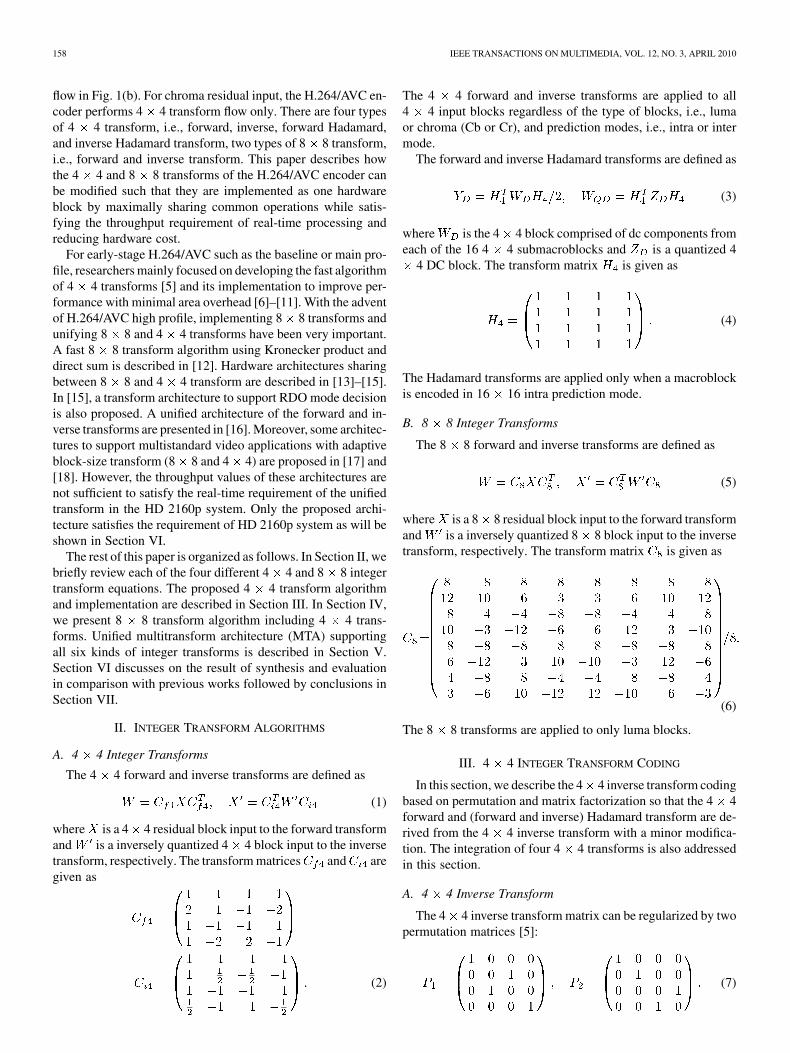
Fig. 1. (a) 4 � 4 transform flow with four different 4 � 4 transforms. (b) 8 �8 transform flow only for luma samples.
The transforms in H.264/AVC require high data throughput
rate for real-time processing in the high-resolution video for-
mats like HD 1080p (1920 1080). Moreover, the mode de-
cision block in H.264 encoder uses ABT iteratively, which re-
sults in further increase of data throughput. Table I shows the
throughput requirements for some example frame sizes obtained
from H.264/AVC reference software in JM14.0. The test video
is “Crowd Run”. In JM14.0 reference software, we set
, high profile, level 5.1, “IPPP..” of GOP, fast full search mo-
tion estimation, single reference frame, and SAD as mode de-
cision metric without rate-distortion optimization (RDO). The
number of tested frames is 50 and frame rate is 50 frames/sec.
Fig. 1 shows various transforms in the H.264/AVC encoding
system. For luma residual input, the H.264/AVC encoder selects
the transform flow between the 4 4 flow in Fig. 1(a) and 8 8
1520-9210/$26.00 © 2010 IEEE
Authorized licensed use limited to: IEEE Xplore. Downloaded on May 13,2010 at 11:51:09 UTC from IEEE Xplore. Restrictions apply.
158 IEEE TRANSACTIONS ON MULTIMEDIA, VOL. 12, NO. 3, APRIL 2010
flow in Fig. 1(b). For chroma residual input, the H.264/AVC en-
coder performs 4 4 transform flow only. There are four types
of 4 4 transform, i.e., forward, inverse, forward Hadamard,
and inverse Hadamard transform, two types of 8 8 transform,
i.e., forward and inverse transform. This paper describes how
the 4 4 and 8 8 transforms of the H.264/AVC encoder can
be modified such that they are implemented as one hardware
block by maximally sharing common operations while satis-
fying the throughput requirement of real-time processing and
reducing hardware cost.
For early-stage H.264/AVC such as the baseline or main pro-
file, researchers mainly focused on developing the fast algorithm
of 4 4 transforms [5] and its implementation to improve per-
formance with minimal area overhead [6]–[11]. With the advent
of H.264/AVC high profile, implementing 8 8 transforms and
unifying 8 8 and 4 4 transforms have been very important.
A fast 8 8 transform algorithm using Kronecker product and
direct sum is described in [12]. Hardware architectures sharing
between 8 8 and 4 4 transform are described in [13]–[15].
In [15], a transform architecture to support RDO mode decision
is also proposed. A unified architecture of the forward and in-
verse transforms are presented in [16]. Moreover, some architec-
tures to support multistandard video applications with adaptive
block-size transform (8 8 and 4 4) are proposed in [17] and
[18]. However, the throughput values of these architectures are
not sufficient to satisfy the real-time requirement of the unified
transform in the HD 2160p system. Only the proposed archi-
tecture satisfies the requirement of HD 2160p system as will be
shown in Section VI.
The rest of this paper is organized as follows. In Section II, we
briefly review each of the four different 4 4 and 8 8 integer
transform equations. The proposed 4 4 transform algorithm
and implementation are described in Section III. In Section IV,
we present 8 8 transform algorithm including 4 4 trans-
forms. Unified multitransform architecture (MTA) supporting
all six kinds of integer transforms is described in Section V.
Section VI discusses on the result of synthesis and evaluation
in comparison with previous works followed by conclusions in
Section VII.
II. INTEGER TRANSFORM ALGORITHMS
A. 4 4 Integer Transforms
The 4 4 forward and inverse transforms are defined as
(1)
where is a 4 4 residual block input to the forward transform
and is a inversely quantized 4 4 block input to the inverse
transform, respectively. The transform matrices and are
given as
(2)
The 4 4 forward and inverse transforms are applied to all
4 4 input blocks regardless of the type of blocks, i.e., luma
or chroma (Cb or Cr), and prediction modes, i.e., intra or inter
mode.
The forward and inverse Hadamard transforms are defined as
(3)
where is the 4 4 block comprised of dc components from
each of the 16 4 4 submacroblocks and is a quantized 4
4 DC block. The transform matrix is given as
(4)
The Hadamard transforms are applied only when a macroblock
is encoded in 16 16 intra prediction mode.
B. 8 8 Integer Transforms
The 8 8 forward and inverse transforms are defined as
(5)
where is a 8 8 residual block input to the forward transform
and is a inversely quantized 8 8 block input to the inverse
transform, respectively. The transform matrix is given as
(6)
The 8 8 transforms are applied to only luma blocks.
III. 4 4 INTEGER TRANSFORM CODING
In this section, we describe the 4 4 inverse transform coding
based on permutation and matrix factorization so that the 4 4
forward and (forward and inverse) Hadamard transform are de-
rived from the 4 4 inverse transform with a minor modifica-
tion. The integration of four 4 4 transforms is also addressed
in this section.
A. 4 4 Inverse Transform
The 4 4 inverse transform matrix can be regularized by two
permutation matrices [5]:
(7)
Authorized licensed use limited to: IEEE Xplore. Downloaded on May 13,2010 at 11:51:09 UTC from IEEE Xplore. Restrictions apply.
HWANGBO AND KYUNG: MULTITRANSFORM ARCHITECTURE FOR H.264/AVC HIGH-PROFILE CODERS 159
Pre- and post-multiplying by and , respectively, and
partitioning into 2 2 blocks, it follows that
(8)
(9)
where
(10)
It is to be noted that and satisfies (
is the 4 4 identity matrix). If we pre-multiply by and
post-multiply it by , the result becomes intuitively, i.e.,
(11)
can then be factored as follows:
(12)
where
(13)
is the 2 2 identity matrix and is the 2 2 null matrix.
Matrix is defined by pre- and post-multiplying by :
(14)
Because , the matrix can be expressed as the
product of and :
(15)
By using (12) and (15) into (11), we obtain
(16)
Then, we can rewrite the inverse transform (1) using (16)
(17)
Since is the symmetric matrix satisfying as are ,
, and , it follows that
(18)
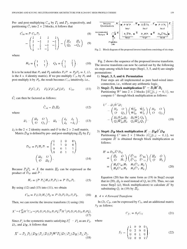
Fig. 2. Block diagram of the proposed inverse transform consisting of six steps.
Fig. 2 shows the sequence of the proposed inverse transform.
The inverse transform can now be carried out by the following
six steps among which four steps (Step1, 3, 5, and 6) are simple
permutations:
1) Step1, 3, 5, and 6: Permutation
Four steps are all implemented as pure hard-wired inter-
connection, i.e., without any arithmetic logic.
2) Step2: block multiplication
Partitioning into 2 2 blocks , we
compute through block multiplication as follows:
(19)
3) Step4: block multiplication
Partitioning into 2 2 blocks , we
compute is obtained through block multiplication as
follows:
(20)
Equation (20) has the same form as (19) in Step2 except
that in (20), is used instead of in (19). Thus, we can
reuse Step2 ( block multiplication) to calculate by
substituting in (19) by .
B. 4 4 Forward Transform
In (2), can be expressed by and an additional matrix
as follows:
(21)
where
(22)
Authorized licensed use limited to: IEEE Xplore. Downloaded on May 13,2010 at 11:51:09 UTC from IEEE Xplore. Restrictions apply.
160 IEEE TRANSACTIONS ON MULTIMEDIA, VOL. 12, NO. 3, APRIL 2010
Fig. 3. Block diagram of the proposed forward transform consisting of sixsteps.
By using (16) into (21), we obtain
(23)
Then, the forward transform can be rewritten as
(24)
Fig. 3 shows the sequence of the proposed forward transform.
Similar to the inverse transform, the forward transform is carried
out by six steps. As Step2, 3, 4, and 5 in sequence in Fig. 3
are the same as Step4, 3, 2, and 5 in sequence in Fig. 2, we
can reuse them as common blocks when integrating the 4 4
forward and inverse transform. Like other permutation, Step1
is implemented as mere hard-wired interconnection. In Step6,
the matrix in (22) is the same as the 4 4 identity matrix
except for scaling factor 2, which is simply left-shift operation.
Thus, Step6 is also implemented as hard-wired interconnection,
which will be shown in the next subsection.
C. 4 4 Hadamard Transform
Applying the same process as the 4 4 inverse transform,
the Hadamard transform matrix can be expanded as follows:
(25)
Then, the forward and inverse Hadamard transform can be
rewritten as
(26)
(27)
Since (26) and (27) have the same equation form as the in-
verse transform (18) except that is used instead of , the
Hadamard transforms can be carried out by the same procedure
as the inverse transform with a minor modification.
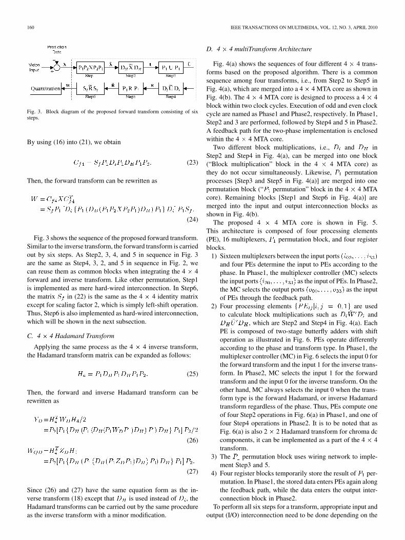
D. 4 4 multiTransform Architecture
Fig. 4(a) shows the sequences of four different 4 4 trans-
forms based on the proposed algorithm. There is a common
sequence among four transforms, i.e., from Step2 to Step5 in
Fig. 4(a), which are merged into a 4 4 MTA core as shown in
Fig. 4(b). The 4 4 MTA core is designed to process a 4 4
block within two clock cycles. Execution of odd and even clock
cycle are named as Phase1 and Phase2, respectively. In Phase1,
Step2 and 3 are performed, followed by Step4 and 5 in Phase2.
A feedback path for the two-phase implementation is enclosed
within the 4 4 MTA core.
Two different block multiplications, i.e., and in
Step2 and Step4 in Fig. 4(a), can be merged into one block
(“Block multiplication” block in the 4 4 MTA core) as
they do not occur simultaneously. Likewise, permutation
processes [Step3 and Step5 in Fig. 4(a)] are merged into one
permutation block (“ permutation” block in the 4 4 MTA
core). Remaining blocks [Step1 and Step6 in Fig. 4(a)] are
merged into the input and output interconnection blocks as
shown in Fig. 4(b).
The proposed 4 4 MTA core is shown in Fig. 5.
This architecture is composed of four processing elements
(PE), 16 multiplexers, permutation block, and four register
blocks.
1) Sixteen multiplexers between the input ports
and four PEs determine the input to PEs according to the
phase. In Phase1, the multiplexer controller (MC) selects
the input ports as the input of PEs. In Phase2,
the MC selects the output ports as the input
of PEs through the feedback path.
2) Four processing elements are used
to calculate block multiplications such as and
, which are Step2 and Step4 in Fig. 4(a). Each
PE is composed of two-stage butterfly adders with shift
operation as illustrated in Fig. 6. PEs operate differently
according to the phase and transform type. In Phase1, the
multiplexer controller (MC) in Fig. 6 selects the input 0 for
the forward transform and the input 1 for the inverse trans-
form. In Phase2, MC selects the input 1 for the forward
transform and the input 0 for the inverse transform. On the
other hand, MC always selects the input 0 when the trans-
form type is the forward Hadamard, or inverse Hadamard
transform regardless of the phase. Thus, PEs compute one
of four Step2 operations in Fig. 6(a) in Phase1, and one of
four Step4 operations in Phase2. It is to be noted that as
Fig. 6(a) is also 2 2 Hadamard transform for chroma dc
components, it can be implemented as a part of the 4 4
transform.
3) The permutation block uses wiring network to imple-
ment Step3 and 5.
4) Four register blocks temporarily store the result of per-
mutation. In Phase1, the stored data enters PEs again along
the feedback path, while the data enters the output inter-
connection block in Phase2.
To perform all six steps for a transform, appropriate input and
output (I/O) interconnection need to be done depending on the
Authorized licensed use limited to: IEEE Xplore. Downloaded on May 13,2010 at 11:51:09 UTC from IEEE Xplore. Restrictions apply.

HWANGBO AND KYUNG: MULTITRANSFORM ARCHITECTURE FOR H.264/AVC HIGH-PROFILE CODERS 161
Fig. 4. (a) Block diagram of the sequence of operations for four 4 � 4 transforms. (b) Proposed 4 � 4 MTA to implement the four transforms on a commonhardware platform.
Fig. 5. First-level details of the proposed MTA core for performing input mul-tiplexing, block multiplication, and � permutation. Step2 and 4 are merged, asare step3 and 5. MC denotes the multiplexer controller. Because 16 output coef-ficients are outputted every two cycles, the processing rate is eight pixels/cycle.
Fig. 6. Second-level details of 2� 2 components in the MTA core. (a) �� .(b) �� . (c) �� . (d) �� . Each PE corresponds to each of the 2 � 2elements of block multiplication in (24), (26), (37), and (43). MC denotes themultiplexer controller. (a) is also 2 � 2 Hadamard transform for chroma dccomponents.
type of transforms. Fig. 7(a) shows the complete 4 4 multi-
transform architecture including the I/O interconnection blocks.
The input interconnection block is composed of four permuta-
tion blocks and one multiplexer to choose an appropriate input to
be processed. The output interconnection block is composed of
three permutation blocks and a multiplication
Authorized licensed use limited to: IEEE Xplore. Downloaded on May 13,2010 at 11:51:09 UTC from IEEE Xplore. Restrictions apply.
162 IEEE TRANSACTIONS ON MULTIMEDIA, VOL. 12, NO. 3, APRIL 2010
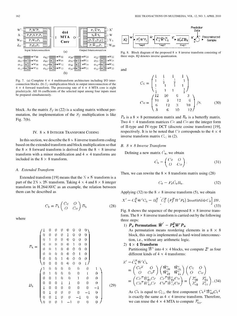
Fig. 7. (a) Complete 4 � 4 multitransform architecture including I/O inter-connection blocks. (b) � multiplication block in output interconnection of the4 � 4 forward transform. The processing rate of 4 � 4 MTA core is eightpixels/cycle. All 16 coefficients of the selected input among four inputs mustbe prepared simultaneously.
block. As the matrix in (22) is a scaling matrix without per-
mutation, the implementation of the multiplication is like
Fig. 7(b).
IV. 8 8 INTEGER TRANSFORM CODING
In this section, we describe the 8 8 inverse transform coding
based on the extended transform and block multiplication so that
the 8 8 forward transform is derived from the 8 8 inverse
transform with a minor modification and 4 4 transforms are
included in the 8 8 transform.
A. Extended Transform
Extended transform [19] means that the transform is a
part of the transform. Taking 4 4 and 8 8 integer
transform in H.264/AVC as an example, the relation between
them can be described as
(28)
where
(29)
Fig. 8. Block diagram of the proposed 8 � 8 inverse transform consisting ofthree steps. IQ denotes inverse quantization.
and
(30)
is a 8 8 permutation matrix and is a butterfly matrix.
Two 4 4 transform matrices and are the integer form
of II-type and IV-type DCT (discrete cosine transform) [19],
respectively. It is to be noted that corresponds to the 4 4
inverse transform matrix in (2).
B. 8 8 Inverse Transform
Defining a new matrix , we obtain
(31)
Then, we can rewrite the 8 8 transform matrix using (28)
(32)
Applying (32) to the 8 8 inverse transform (5), we obtain
(33)
Fig. 8 shows the sequence of the proposed 8 8 inverse trans-
form. The 8 8 inverse transform is carried out by the following
three steps:
1) Permutation:
As permutation means reordering elements in a 8 8
block, this step is implemented as hard-wired interconnec-
tion, i.e., without any arithmetic logic.
2) Transform
Partitioning into 4 4 blocks, we compute as four
different kinds of 4 4 transforms:
(34)
As is equal to , the first component
is exactly the same as 4 4 inverse transform. Therefore,
we can reuse the 4 4 MTA to compute .
Authorized licensed use limited to: IEEE Xplore. Downloaded on May 13,2010 at 11:51:09 UTC from IEEE Xplore. Restrictions apply.
HWANGBO AND KYUNG: MULTITRANSFORM ARCHITECTURE FOR H.264/AVC HIGH-PROFILE CODERS 163
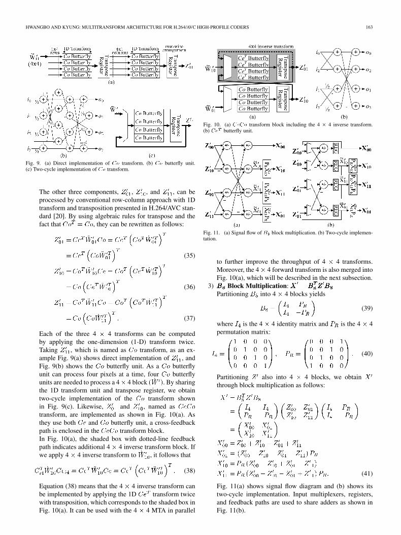
Fig. 9. (a) Direct implementation of �� transform. (b) �� butterfly unit.(c) Two-cycle implementation of �� transform.
The other three components, , , and , can be
processed by conventional row-column approach with 1D
transform and transposition presented in H.264/AVC stan-
dard [20]. By using algebraic rules for transpose and the
fact that , they can be rewritten as follows:
(35)
(36)
(37)
Each of the three 4 4 transforms can be computed
by applying the one-dimension (1-D) transform twice.
Taking , which is named as transform, as an ex-
ample Fig. 9(a) shows direct implementation of , and
Fig. 9(b) shows the butterfly unit. As a butterfly
unit can process four pixels at a time, four butterfly
units are needed to process a 4 4 block . By sharing
the 1D transform unit and transpose register, we obtain
two-cycle implementation of the transform shown
in Fig. 9(c). Likewise, and , named as
transform, are implemented as shown in Fig. 10(a). As
they use both and butterfly unit, a cross-feedback
path is enclosed in the transform block.
In Fig. 10(a), the shaded box with dotted-line feedback
path indicates additional 4 4 inverse transform block. If
we apply 4 4 inverse transform to , it follows that
(38)
Equation (38) means that the 4 4 inverse transform can
be implemented by applying the 1D transform twice
with transposition, which corresponds to the shaded box in
Fig. 10(a). It can be used with the 4 4 MTA in parallel
Fig. 10. (a) ���� transform block including the 4 � 4 inverse transform.(b) �� butterfly unit.
Fig. 11. (a) Signal flow of � block multiplication. (b) Two-cycle implemen-tation.
to further improve the throughput of 4 4 transforms.
Moreover, the 4 4 forward transform is also merged into
Fig. 10(a), which will be described in the next subsection.
3) Block Multiplication:
Partitioning into 4 4 blocks yields
(39)
where is the 4 4 identity matrix and is the 4 4
permutation matrix:
(40)
Partitioning also into 4 4 blocks, we obtain
through block multiplication as follows:
(41)
Fig. 11(a) shows signal flow diagram and (b) shows its
two-cycle implementation. Input multiplexers, registers,
and feedback paths are used to share adders as shown in
Fig. 11(b).
Authorized licensed use limited to: IEEE Xplore. Downloaded on May 13,2010 at 11:51:09 UTC from IEEE Xplore. Restrictions apply.

164 IEEE TRANSACTIONS ON MULTIMEDIA, VOL. 12, NO. 3, APRIL 2010
Fig. 12. Block diagram of the proposed 8� 8 forward transform consisting ofthree steps. Q denotes quantization.
Fig. 13. (a) ���� transform block including the 4 � 4 forward transform.(b) �� butterfly unit including � �� � � �.
C. 8 8 Forward Transform
The 8 8 forward transform can be expanded as follows
using the similar process as the 8 8 inverse transform:
(42)
Fig. 12 shows the sequence of the proposed 8 8 forward trans-
form. As Step1 in Fig. 12 is the same as Step3 in Fig. 8 ex-
cept that the position of transpose, Step1 can be implemented
by reusing the multiplication block in Fig. 11(b). Step3 is
the permutation which can be implemented as hard-wired inter-
connection. In Step2, we obtain following four different kinds
of 4 4 transforms by applying 4 4 block partitioning:
(43)
As is equal to , the first component can be
expanded by the same procedure as 4 4 transforms:
(44)
Equation (44) is the same as (24) in the 4 4 forward transform
except that in (24) is removed in (44). Thus, we can reuse the
4 4 MTA to compute by bypassing the multiplication
block in Fig. 7.
Fig. 13(a) shows the transform block for computing
and . The butterfly unit in Fig. 10(b) is replaced
by butterfly unit as shown in Fig. 13(b). As
Fig. 14. Butterfly unit unifying �� and ��.
Fig. 15. Proposed MTA supporting six different kinds of transforms.
and , the 4 4 forward transform matrix is
equal to , which is implemented by selecting the multi-
plexer terminal 0 in Fig. 13(b). Thus, the 4 4 forward trans-
form can also be implemented along the dotted-line feedback
path in Fig. 13(a).
To compute the 8 8 forward and inverse transform in one
transform architecture, and butterfly units are unified as
shown in Fig. 14. As it also includes the 4 4 forward transform
matrix, the transform block in Fig. 13(a) can process 8
8 forward, 8 8 inverse, 4 4 forward, and 4 4 inverse
transform by using the unified butterfly unit in Fig. 14.
V. MULTITRANSFORM ARCHITECTURE UNIFYING
8 8 AND 4 4 INTEGER TRANSFORMS
Fig. 15 shows the proposed MTA supporting six different
kinds of transforms for H.264/AVC high profile encoder. The
MTA is composed of a block multiplication block, four 4 4
transform blocks, two permutation blocks, and multiplexers.
The block multiplication, transform, and permutation
blocks are used only for the 8 8 transforms. The 4 4 MTA
and transform blocks are used for both 4 4 and 8 8
transforms.
For performing four 4 4 transforms (4 4 forward, 4
4 inverse, forward Hadamard, and inverse Hadamard), two 4
Authorized licensed use limited to: IEEE Xplore. Downloaded on May 13,2010 at 11:51:09 UTC from IEEE Xplore. Restrictions apply.

HWANGBO AND KYUNG: MULTITRANSFORM ARCHITECTURE FOR H.264/AVC HIGH-PROFILE CODERS 165
Fig. 16. Temporal diagram of two-stage pipelined transform. (a) 8� 8 forwardtransform. (b) 8 � 8 inverse transform. Each stage takes two clock cycles.
Fig. 17. Block diagram for functional verification of the proposed multitrans-form hardware using testbench from the JM reference software.
4 transform blocks, 4 4 MTA and part of trans-
form block, are used to double the throughput compared to using
only 4 4 MTA. Such throughput allows the proposed MTA to
process the transforms of HD 2160p video (3840 2160 at 50
frames/sec) in real time whose throughput requirement is de-
scribed in Table I, which is further discussed in Section VI.
Unifying the 8 8 forward and inverse transform is simple
because three functional blocks in each transform are almost the
same while only their sequences are reversed as shown in Fig. 8
and Fig. 12. Multiplexers and feedback paths are used to unify
the 8 8 forward and inverse transform as shown Fig. 15 in
which dotted-line paths are used for the case of performing the
8 8 inverse transform.
To process a 8 8 block using the MTA takes four clock
cycles because block multiplication takes two clock cycles
and 4 4 transform block takes two clock cycles. However, by
applying two-stage pipelining to 8 8 transforms as shown in
Fig. 16, the throughput can be doubled, i.e., one 8 8 block
every two clock cycles.
VI. IMPLEMENTATION AND RESULTS
A. Implementation and Verification
We have implemented the proposed multitransform de-
sign and verified its behavior using Verilog RTL simulation,
logic synthesis, and gate-level simulation. Fig. 17 shows the
simulation environment to verify the functional behavior of
the proposed architecture. Test vectors are obtained by using
H.264/AVC reference software in JM14.0 version. After ex-
tracting input and output data from the reference software, we
applied input data to the proposed design and compared its
result with output data from the reference software.
We synthesized the proposed multitransform design by using
Synopsys Design Compiler and UMC 0.18 Faraday stan-
TABLE IISYNTHESIS RESULTS AND HARDWARE RESOURCE COMPARISON BETWEEN THE
SINGLE TRANSFORM AND MULTITRANSFORM DESIGN. EACH TRANSFORM HAS
THE SAME OPERATING FREQUENCY OF 200 MHz
FT, IT, FHT, and IHT denote the forward, inverse, forward Hadamard, and
inverse Hadamard transform, respectively. ABT denotes adaptive block-size
transform with 4 � 4 and 8 � 8 block sizes.
DPR denotes data processing rate.
dard cell library [21]. In the logic synthesis, wireload
model was used and skew, jitter, transition time of clock, and
I/O external delay were separately taken into account. Table II
shows the performance and hardware cost of the proposed mul-
titransform design compared with the separate implementation
of the six transforms. Timing constraints are identical so that
each transform has the same operating frequency of 200 MHz.
The single transform design, which is a separate implementation
of four 4 4 transform paths in Fig. 4(a) and two 8 8 trans-
form paths in Figs. 8 and 12, performs the same behavior as the
multitransform design and is used as the target for comparison.
According to Table II, the proposed MTA has about 51%
less area than the single transform. Table II shows that the pro-
posed MTA can process 3.2 Gpixels/sec when it processes only
4 4 transforms. Because the MTA includes two 4 4 trans-
form blocks, i.e., 4 4 MTA and transform block each
of which can process a 4 4 block within two clock cycles,
the MTA has the data processing rate of 16 pixels/cycle. If the
MTA processes only 8 8 transforms, the throughput becomes
6.4 Gpixels/sec.
B. Performance Comparison
When adaptive block-size transform (ABT) which uses 4
4 and 8 8 transform jointly is used, we obtain the throughput
of 4.1 Gpixels/sec. It is based on the observation that the ratio
of clock cycles spent for 4 4 mode to those spent for 8 8
block mode is 2.5. This was obtained from Table I considering
one cycle is required to process a 4 4 block and two cycles
are required to process a 8 8 block. Thus, the proposed de-
sign can allow real-time processing of HD 2160p video (3840
2160 at 50 frames/sec) whose throughput requirement is de-
scribed in Table I. Table III shows the comparison among var-
ious methods in terms of operating frequency, data processing
rate, throughput, gate count, and throughput per area. There are
three different transform modes, i.e., 4 4, 8 8, and ABT.
The results on the 4 4 and 8 8 mode are based on an as-
sumption that each transform hardware performs either 4 4
Authorized licensed use limited to: IEEE Xplore. Downloaded on May 13,2010 at 11:51:09 UTC from IEEE Xplore. Restrictions apply.
166 IEEE TRANSACTIONS ON MULTIMEDIA, VOL. 12, NO. 3, APRIL 2010
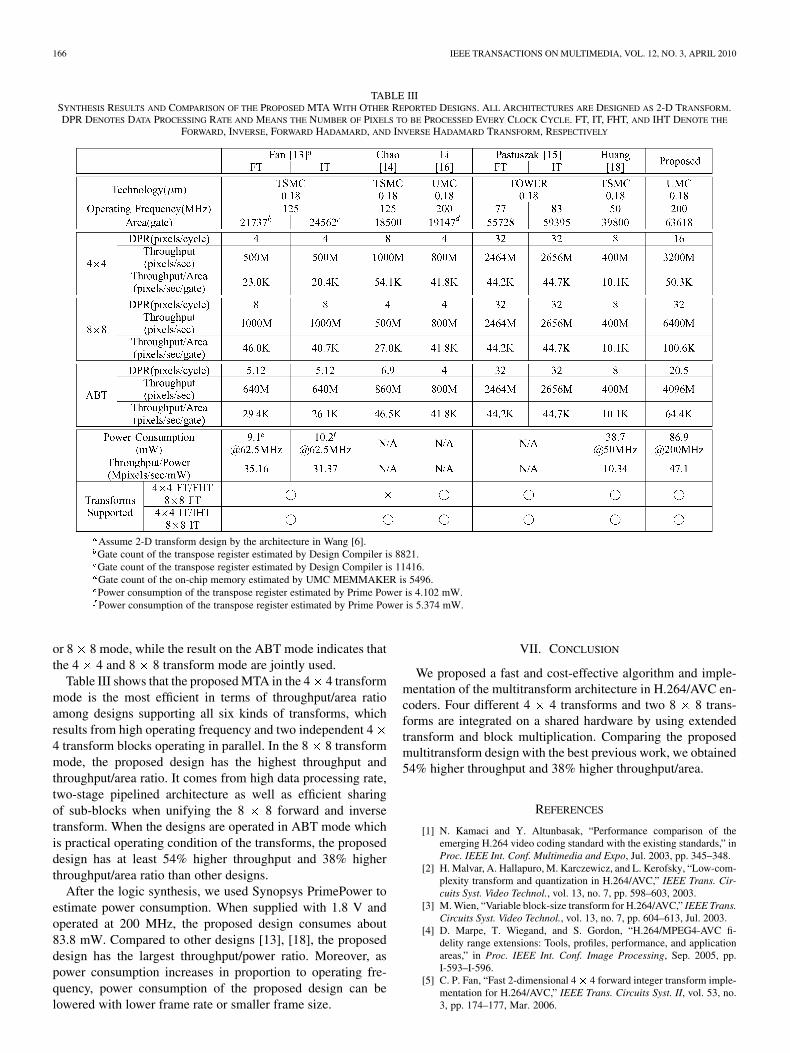
TABLE IIISYNTHESIS RESULTS AND COMPARISON OF THE PROPOSED MTA WITH OTHER REPORTED DESIGNS. ALL ARCHITECTURES ARE DESIGNED AS 2-D TRANSFORM.DPR DENOTES DATA PROCESSING RATE AND MEANS THE NUMBER OF PIXELS TO BE PROCESSED EVERY CLOCK CYCLE. FT, IT, FHT, AND IHT DENOTE THE
FORWARD, INVERSE, FORWARD HADAMARD, AND INVERSE HADAMARD TRANSFORM, RESPECTIVELY
Assume 2-D transform design by the architecture in Wang [6].
Gate count of the transpose register estimated by Design Compiler is 8821.
Gate count of the transpose register estimated by Design Compiler is 11416.
Gate count of the on-chip memory estimated by UMC MEMMAKER is 5496.
Power consumption of the transpose register estimated by Prime Power is 4.102 mW.
Power consumption of the transpose register estimated by Prime Power is 5.374 mW.
or 8 8 mode, while the result on the ABT mode indicates that
the 4 4 and 8 8 transform mode are jointly used.
Table III shows that the proposed MTA in the 4 4 transform
mode is the most efficient in terms of throughput/area ratio
among designs supporting all six kinds of transforms, which
results from high operating frequency and two independent 4
4 transform blocks operating in parallel. In the 8 8 transform
mode, the proposed design has the highest throughput and
throughput/area ratio. It comes from high data processing rate,
two-stage pipelined architecture as well as efficient sharing
of sub-blocks when unifying the 8 8 forward and inverse
transform. When the designs are operated in ABT mode which
is practical operating condition of the transforms, the proposed
design has at least 54% higher throughput and 38% higher
throughput/area ratio than other designs.
After the logic synthesis, we used Synopsys PrimePower to
estimate power consumption. When supplied with 1.8 V and
operated at 200 MHz, the proposed design consumes about
83.8 mW. Compared to other designs [13], [18], the proposed
design has the largest throughput/power ratio. Moreover, as
power consumption increases in proportion to operating fre-
quency, power consumption of the proposed design can be
lowered with lower frame rate or smaller frame size.
VII. CONCLUSION
We proposed a fast and cost-effective algorithm and imple-
mentation of the multitransform architecture in H.264/AVC en-
coders. Four different 4 4 transforms and two 8 8 trans-
forms are integrated on a shared hardware by using extended
transform and block multiplication. Comparing the proposed
multitransform design with the best previous work, we obtained
54% higher throughput and 38% higher throughput/area.
REFERENCES
[1] N. Kamaci and Y. Altunbasak, “Performance comparison of theemerging H.264 video coding standard with the existing standards,” inProc. IEEE Int. Conf. Multimedia and Expo, Jul. 2003, pp. 345–348.
[2] H. Malvar, A. Hallapuro, M. Karczewicz, and L. Kerofsky, “Low-com-plexity transform and quantization in H.264/AVC,” IEEE Trans. Cir-
cuits Syst. Video Technol., vol. 13, no. 7, pp. 598–603, 2003.[3] M. Wien, “Variable block-size transform for H.264/AVC,” IEEE Trans.
Circuits Syst. Video Technol., vol. 13, no. 7, pp. 604–613, Jul. 2003.[4] D. Marpe, T. Wiegand, and S. Gordon, “H.264/MPEG4-AVC fi-
delity range extensions: Tools, profiles, performance, and applicationareas,” in Proc. IEEE Int. Conf. Image Processing, Sep. 2005, pp.I-593–I-596.
[5] C. P. Fan, “Fast 2-dimensional 4� 4 forward integer transform imple-mentation for H.264/AVC,” IEEE Trans. Circuits Syst. II, vol. 53, no.3, pp. 174–177, Mar. 2006.
Authorized licensed use limited to: IEEE Xplore. Downloaded on May 13,2010 at 11:51:09 UTC from IEEE Xplore. Restrictions apply.

HWANGBO AND KYUNG: MULTITRANSFORM ARCHITECTURE FOR H.264/AVC HIGH-PROFILE CODERS 167
[6] T. C. Wang, Y. W. Huang, H. C. Fang, and L. G. Chen, “Parallel 4� 42D transform and inverse transform architecture for MPEG-4 AVC/H.264,” in Proc. IEEE Int. Symp. Circuits and Systems, May 2003, pp.800–803.
[7] Z. Y. Cheng, C. Chen, B. D. Liu, and J. F. Yang, “High throughput2-D transform architectures for H.264 advanced video coders,” inProc. IEEE Asia-Pacific Conf. Circuits and Systems, Dec. 2004, pp.1141–1144.
[8] K. H. Chen, J. I. Guo, and J. S. Wang, “A high-performance direct
2-D transform coding IP design for MPEG-4 AVC/H.264,” IEEE Trans.
Circuits Syst. Video Technol., vol. 16, no. 4, pp. 472–483, Apr. 2006.[9] W. Hwangbo, J. Kim, and C. M. Kyung, “A high-performance 2-D
inverse transform architecture for the H.264/AVC decoder,” in Proc.
IEEE Int. Symp. Circuits and Systems, May 2006, pp. 1613–1616.[10] P. Chungan, Y. Dunshan, C. Xixin, and S. Shimin, “A new high
throughput VLSI architecture for H.264 transform and quantization,”in Proc. Int. Conf. ASIC, Oct. 2007, pp. 950–953.
[11] C. Wei, H. Hui, L. Jinmei, T. Jiarong, and M. Hao, “A high-perfor-mance reconfigurable 2-D transform architecture for H.264,” in Proc.
IEEE Int. Conf. Electronics, Circuits and Systems, Aug. 2008, pp.606–609.
[12] C. P. Fan, “Fast 2-dimensional 8 � 8 integer transform algorithm de-sign for H.264/AVC fidelity range extensions,” IEICE Trans. Inf. Syst.,vol. E89-D, pp. 3006–3011, Dec. 2006.
[13] C. P. Fan, “Cost-effective hardware sharing architectures of fast 8 �8 and 4 � 4 integer transforms for H.264/AVC,” in Proc. IEEE Asia
Pacific Conf. Circuits and Systems, Dec. 2006, pp. 776–779.[14] Y. C. Chao, H. H. Tsai, Y. H. Lin, J. F. Yang, and B. D. Liu, “A novel
design for computation of all transforms in H.264/AVC decoders,” inProc. IEEE Int. Conf. Multimedia and Expo, Jul. 2007, pp. 1914–1917.
[15] G. Pastuszak, “Transforms and quantization in the high-throughputH.264/AVC encoder based on advanced mode selection,” in Proc.
IEEE Comput. Soc. Annu. Symp. VLSI, Apr. 2008, pp. 203–208.
[16] Y. Li, Y. He, and S. Mei, “A highly parallel joint VLSI architecture fortransforms in H.264/AVC,” J. Signal Process. Syst., vol. 50, pp. 19–32,Oct. 2007.
[17] B. Li, D. Zhang, J. Fang, L. Wang, and M. Zhang, “A unified IDCTarchitecture for multi-standard video codecs,” in Proc. Int. Conf. ASIC,Oct. 2007, pp. 962–965.
[18] C. Y. Huang, L. F. Chen, and Y. K. Lai, “A high-speed 2-D transformarchitecture with unique kernel for multi-standard video applications,”in Proc. IEEE Int. Symp. Circuits and Systems, May 2008, pp. 21–24.
[19] W. Chen, C. Smith, and S. Pralick, “A fast computational algorithm forthe discrete cosine transform,” IEEE Trans. Commun., vol. 25, no. 9,pp. 1004–1009, Sep. 1977.
[20] Advanced Video Coding for Generic Audiovisual Services, ITU-T Rec-
ommendation H.264, Std., 2007.[21] Faraday UMC Standard Library. [Online]. Available: http://www.
faraday-tech.com.
Woong Hwangbo received the B.S. degree in elec-trical engineering from Pusan National University,Busan, Korea, and the M.S. degrees in electricalengineering from Korea Advanced Institute ofScience and Technology (KAIST), Daejeon, Korea.He is currently pursuing the Ph.D. degree in theDepartment of Electrical Engineering and ComputerScience at KAIST.
His research interests include VLSI design andmultimedia application with high performance andlow power consumption.
Chong-Min Kyung (S’76–M’81–SM’99–F’08)received the B.S. degree in electronics engineeringfrom Seoul National University, Seoul, Korea, in1975 and the M.S. and Ph.D. degrees in electricalengineering from Korea Advanced Institute ofScience and Technology (KAIST), Daejeon, Korea,in 1977 and 1981, respectively.
From April 1981 to January 1983, he workedat Bell Telephone Laboratories, Murray Hill, NJ,as a postdoc. Since he joined KAIST in 1983, hehas been working on System-on-a-Chip design and
verification methodology as well as processor and graphics architectures forhigh-speed and/or low-power applications, including mobile video codec. Heis Hynix Chair Professor at KAIST
Dr. Kyung received the Most Excellent Design Award, and Special FeatureAward in the University Design Contest in the ASP-DAC 1997 and 1998, re-spectively. He received the Best Paper Awards in the 36th DAC held in New Or-leans, LA; the 10th International Conference on Signal Processing Applicationand Technology (ICSPAT), Orlando, FL, in September 1999; and the 1999 Inter-national Conference on Computer Design (ICCD), Austin, TX. He was GeneralChair of Asian Solid-State Circuits Conference (A-SSCC) 2007, and ASP-DAC2008. In 2000, he received a National Medal from the Korean government forhis contribution to research and education in IC design. He is a member of theNational Academy of Engineering Korea (NAEK) and the Korean Academy ofScience and Technology (KAST).
Authorized licensed use limited to: IEEE Xplore. Downloaded on May 13,2010 at 11:51:09 UTC from IEEE Xplore. Restrictions apply.