Embed Size (px)
Citation preview

A MULTIPLE-CONSTRUCTS FRAMEWORK FOR
TEACHING CONTROL CONCEPTS
Ilya Levin David Mioduser
Tel-Aviv University Tel-Aviv UniversitySchool of Education School of Education Ramat-Aviv, 69978 Ramat-Aviv, 69978
e-mail: [email protected] e-mail: [email protected]
Final version published in:IEEE Transactions on Education, 39(4), 1996 (pp. 1-9)
© by the publisher

Running head: MULTIPLE-CONSTRUCTS FRAMEWORK

Abstract
The phenomenon of control is an essential component of our everyday natural, social
and artificial environment. Control-related concepts have become a central
component of many core topics in modern technology education. However, our
knowledge about the students' ability to understand (analysis) and design (synthesis)
controlled systems is still poor. Evidence already collected shows that students have
serious difficulties in transcending the phenomenal or behavioral understanding of a
system's functioning, towards more formal definitions of the control process. In this
paper a framework to start dealing with these and related issues is proposed. First,
the nature of controlled systems is discussed. Then a conceptual framework
encompassing a variety of perspectives on and approaches to control is presented.
The framework consists of two main components: the process component and the
representational component. The first relates to the stages in the process of defining
and implementing control. The second is the repertoire of constructs used for
defining and implementing control. Two main paradigms are suggested as the
conveyors of very different cognitive approaches to control: programming and design
paradigms. Finally the educational implications of the proposed framework at both
the cognitive and the instructional levels are discussed.

A MULTIPLE-CONSTRUCTS FRAMEWORK FOR
TEACHING CONTROL CONCEPTS
Introduction
The phenomenon of control is an essential component of our everyday natural,
social and artificial environment [1] - [2], and control-related concepts have become a
central component of many core topics in modern technology education [3] - [4] - [5].
Computers, programmable controllers, CNC, CAM, dynamic systems and other
important subjects of the technology curriculum are based on the general idea of
control.
However, our knowledge about the students' ability to understand (analysis) and
design (synthesis) controlled systems is still poor. Evidence already collected [6] -
[7] - [8] - [9] shows that students have serious difficulties in transcending the
phenomenal or behavioral understanding of a system's functioning, towards more
formal definitions of the control process. For example, Ackerman's [8] subjects think
in terms of transactions among elements, where element “a” does something (or tells
to do something) to “b”. The actors (“a” and “b”) are being alternatively animated
according to “who” impacts (or is impacted by) “whom”. Mioduser et al.’s [9]
subjects related controlling functions to particular physical components (e.g., sensors,
motors), assumed as responsible for making the decisions governing the system's
behavior. Most students were able to identify control functions, but only part of them
were able to formally define the control specifications and procedures.
Two additional aspects further complicate the picture. The first is related to
prerequisite knowledge. Dealing with controlled systems means in the first place

dealing with systems in general, the control component being a subsystem of the
whole system. Concepts like system, information flow within the system, and
feedback (among many others) are the necessary background for studying the more
particular topic of control. Although we are aware of the need for this prerequisite
knowledge, we will focus in this paper on the specific issues of controlled systems.
The second source for potential difficulties relates to the variety of perspectives
in conceiving control. For example, we may think of the engineer's view of a
controller as a collection of logical components designed to transform inputs into
outputs, as opposed to the programmer’s view of control as the running of a computer
program that guides a device's performance. We will later refer to these and other
alternative approaches as different control paradigms. We will also propose that the
differences among the paradigms could be the source of different cognitive and
instructional approaches for learning and teaching control.
Teaching control (analysis and design) concepts implies facing several key
questions, such as:
- How is the concept of control conceived (or misconceived) by students at
different age levels? How do these conceptions develop?
- What (mental) model of control will be appropriate to teach to students at
different age levels seeking different learning goals (e.g., school age children
acquiring technological literacy, technicians being trained to repair a device)?
- How do different paradigms for defining and representing control affect
people's conceptions, both for analysis and design purposes?
- How do the interaction between the system's level of complexity and the
paradigm used for defining its control affect people's conceptions?

- How should the instruction of control concepts be planned (e.g., content,
learning environment, representational formalisms, computer implementation
tools)?
In this paper we propose a framework to start dealing with these and related
questions. First, we will briefly refer to the nature of controlled systems. Then we
will propose a conceptual framework encompassing a variety of perspectives on and
approaches to control. Finally we will refer to the educational implications of the
proposed framework, at both the cognitive and the instructional levels.
Controlled Systems
Several technological developments in the 1940’s can be viewed as a turning
point in the contemporary history of controlled systems. These developments made
possible the building of electronic switching machines for executing calculations and
stored programs, and of self-regulating computing devices. This nascent field of
control and communication was named “cybernetics” by Wiener [10].
The most representative system of this (since then) rapidly growing field is the
computer. The first computer systems were developed using electronic elements,
assembled for performing certain functions. The first problem to arise in the process
of development of these systems was that of design. In other words, the problem was
to find a method for creating any computer system. Such a method was developed. It
is based on the principle of dividing the system into two main components: operating
unit (OU) and control unit (CU). The operating unit contains performing elements
(e.g., adders, counters, registers). The control unit implements the algorithm of the
processing of information.

Figure 1 consists of a representation of the structure of a general controlled
system. The set X={x1,…xL} of binary signals, transferred from the OU to the CU
can be named the world state of the system. The set of binary signals Y={y1,…,yN}
sent by the CU to the OU is the set of microoperations affecting the OU's behavior.
The goal of the CU is the generation of a sequence of signals Y, distributed in time.
The functioning of the OU is dictated by this sequence.
Insert Figure 1 about here
Many examples of devices and systems that can be viewed as instances of the
above presented structure are part of our immediate physical environment. An
interesting example of such systems is nowadays being introduced into schools in the
form of building and programming kits (e.g., the Lego-Logo kits). These kits allow
the students to build physical devices by means of modular building bricks, and to
write computer programs to control the functioning of these devices [11]. The brick
structures can be defined as the operating units of the system, while the computer
program can be viewed as the implementation of the system’s control unit.
These building and programming kits offer a unique opportunity for teaching
and learning control concepts. But for this potential to be realized their
implementation should be supported both at the cognitive and the curricular levels.
This involves the development of appropriate instructional materials and learning
environments side by side with the systematic study of the learning process of
control-related concepts and skills.

In the following we want to suggest a conceptual framework for dealing with
the required cognitive and curricular effort: a multiple-constructs framework for
control.
A Multiple-Constructs Framework for Control
This framework is intended to serve as reference for the design of the
instruction, as well as for the formulation of key research questions and research
plans. To clarify its presentation, we will use all along the example of a particular
device built with the Lego bricks. This device will serve to illustrate the different
control constructs and approaches in our model. The device (Figure 2) was equipped
with two motors and a light sensor, and could be defined as a “line-seeker device”. It
moves on a surface following a black line drawn on it. Whenever the line-seeker gets
to one end of the line it makes a turn until it “finds” the line again, continues to
follow it to the other end, and so on.
Insert Figure 2 about here
The proposed framework consists of two main components: the process
component and the representational component. The first relates to the stages in the
process of defining and implementing control. The second is the repertoire of
constructs used for defining and implementing control. These two components are
presented in the next two sections.
Process for Defining and Implementing Control

We propose a didactic sequence of three stages for describing and/or designing
the control part of a system: its initial description or definition, its formal model, and
its implementation.
We will call the preliminary and descriptive explanation of the behavior of the
system the initial description of its control part. The question to be answered at this
stage is “What is the observed or desired behavior of the system?” The expected
answer will be a natural language description of that behavior.
At the next stage, we will look for an exact expression of the initial description,
using a specific formal notation. The question to be answered here is “What is the
exact (formal) description of the system's desired behavior?”, the answer constituting
the formal model of the control part of the system.
Finally we will ask the question of “How will control be actually
implemented?” The outcome of this stage will be a working version of the control
module which provokes the device to perform the desired behavior.
Repertoire of Constructs for Defining and Implementing Control
The second component of our framework refers to the alternative constructs we
may use for representing control at the three stages mentioned in the previous section.
The control research and development field offers a rich repertoire of notation
systems and means of implementation [12] - [13] - [14] - [15] - [16]. Some of these
constructs are everyday working-tools for engineers, designers and programmers
dealing with control-related tasks. However, for the study of the teaching and
learning of control, we found it necessary to rearrange and reorganize the disciplinary
knowledge and tools so as to respond to our curricular and cognitive concerns. In our
model we have chosen a particular set of constructs which we considered the more
relevant for our purpose, and we arranged the constructs as shown in Figure 3.
Insert Figure 3 about here
As suggested in the previous section, at the initial description stage the outcome
is a behavioral description of the system's functioning. For our example of the line-
seeking device the behavioral description could be as follows:
The device should always look for the line. When it is on the right side of the
line, it has to turn to the left, until reaching the line again. If it passes the line
to its left side, the device has to turn to the right until reaching the line again.
At the end of the line the device has to continue turning until it reaches the line
again.
Given the behavioral description of the system's (observed or desired)
functioning, from the formal model stage onwards we suggest the distinction between
two main paradigms: the programming paradigm and the design paradigm. In this
paper we will elaborate on the assumption that these two paradigms represent two
clearly separate and distinguishable approaches for defining and implementing
control. They imply different (mental) modeling of control phenomena, different
methodologies and means, and even different academic and professional disciplines.
The Programming Paradigm. By the programming paradigm, the person
(e.g., student, user, technician, designer) assumes the existence of a control performer
(e.g., a microprocessor), in charge of running the control specifications. This kind of

CU can be defined as a programmable controller. By this paradigm, to create control
means to create an appropriate program.
Within the programming paradigm, several approaches can be taken. Here we
will describe two examples: the algorithmic and the functional approaches. Let us
describe these approaches for the next two levels of the control design process,
namely, the formal-model definition stage and the implementation stage.
The key formal construct for the algorithmic paradigm is the flowchart (Figure
4). A flowchart is a directed connected graph which includes an initial vertex, a final
vertex and a finite set of operator and conditional vertices. The final, operator and
conditional vertices have only one input, and the initial vertex has no input. Initial
and operator vertices have only one output, and conditional vertices have two outputs
marked as “1” and “0”. The final vertex has no outputs.
Defining characteristics for a flowchart are also the following:
(a) Output vertices are connected by arcs to input vertices. Every output is
connected only to one input, every input is connected from at least one output. One
of the outputs of a conditional vertex can be connected to its input forming a waiting
vertex (since it simulates a waiting cycle in the system’s functioning).
(b) Every vertex is part of at least one path leading from the initial vertex to the
final vertex.
(c) A logical condition from set X appears in each conditional vertex. A given
logical condition may appear in different conditional vertices.
(d) A microinstruction or operator Yi (a subset of the set of microoperations Y)
appears in every operator vertex. A given operator may appear in different operator
vertices.

The flowchart constructed for our example is shown in Figure 4. The motors
will be activated depending on the sensor's input values (“x1” being either 0 or 1).
Insert Figure 4 about here
A common implementation of the algorithmic approach could be a program
written in BASIC or similar programming languages.
The second approach is based on the concept of function. We may refer to the
D-function calculus as the formal construct for the functional approach. The basic D-
function definition is:
Di = D1#...#Dj meaning that D-function D1 isperformed before D-function Dj.
Dj = αj1D1+...+αjKDK+αjmY1+...+αjMYM where αjk is a boolean function of theinput variables X={x1...xL}, and:
⊇Dk, if αjk=1αjkDk = ⊂ ⊄0, if αjk=0
At the implementation stage, we may use a functional programming language
for implementing control. In such a language, all procedures are well-defined
functions of their arguments [17]. The most popular example of a functional
programming language in education is Logo. The D-functional description of the
line-seeking device’s control and the corresponding Logo program are shown in
Figure 5.

Insert Figure 5 about here
The program example is written in TC-Logo, the version of the language used
in the Lego-Logo building and programming kits. The main procedure (D1) runs the
sequence of “D” procedures. D0 and D1 check the inputs and run the correspondent
procedures for activating (Y1) or deactivating (Y0) the motors.
The Design Paradigm. By following the design paradigm, the person (e.g.,
student, user, technician, designer) focuses on the logical scheme inside the CU,
implemented by means of logical elements of varied nature (e.g., logical gates,
contacts, programmable logical devices). For the previous programming paradigm
the CU was defined as a programmable controller. Now we will define it as
designable controller. To create control means to design the configuration of
elements most appropriate for generating the desired behavior.
A key idea within the design paradigm is that the system is conceived as a finite
state machine. The CU can be characterized by its state and may perform different
functions (i.e., changing to other states) with the same input, depending upon the
current state. The formal construct we consider the more appropriate for the formal-
model definition is the state diagram (Figure 6). The state diagram is a representation
of the system's possible states and the transitions among them. The nodes in the
graph indicate states (a1, a2,...aM), and the arrows the transitions between states
according to the input values which would cause such transitions. Figure 6 shows the
state diagram for our example, the line-seeking device. Also in the figure appears the
state table, a tabular form of the state diagram. The columns in the table indicate the

current state, the alternative input values, the corresponding output, and the next
stage.
Insert Figure 6 about here
Against this background, we may define control as the process by which the
system's transition from one state to another occurs. That implies that the system
could be, at one time, in any of a number of possible states; that there are conditions
under which a change in state takes place; and that control implies choice.
Representing the system as a finite-state machine is usually called abstract
synthesis. At this level of description we deal purely with input-output
transformations, ignoring the structure of the control unit. At the next stage we also
have to take into account the internal structure of the CU, that is, we have to create
the structure of the CU. This stage of design is usually called structural synthesis. We
will use here the most popular structure of CU - the canonical structure or sequential
machine. The canonical structure of the control unit is shown in Figure 7.
Insert Figure 7 about here
According to the canonical structure the control unit consists of two
components. The first is the combinational scheme (CS), containing the set of
elementary elements (or building blocks). The second is the memory register (M),
built out of two-states elements (e.g., flip-flops). The control unit receives as inputs
incoming data from the operating unit (vector X={x1,…xL}) and the current state

(vector T={T1,…,TR}) as stored in the memory register, thus generating its outputs
(vector Y={y1,…,yN}). The new state is then stored in the memory (vector
D={D1,…,DR}).
We may think of implementing the structure of the CS in several ways, e.g.
logical gates, Programmable Read Only Memory structure (PROM). As an example
we will refer to two alternative constructs: PROM structure and relay scheme.
Figure 8 shows the PROM implementation for the line-seeking device in our
example. This kind of construct focuses on the logical configuration of the structure
of the CU.
Insert Figure 8 about here
The structure comprises the PROM (combinational part) and three RS flip-flops.
The PROM consists of a fixed AND array, and a programmable OR array [18].
Figure 9 illustrates the relay scheme implementing the control unit of our
example. We adopted here a widely used representation, the ladder diagram [15].
A ring of a ladder diagram program is a graphical representation of a Boolean
assignment statement. The dependent variable of the logical equation is represented
by a circle. The independent variables (the ring inputs) are represented by pairs of
small vertical parallel bars. A horizontal line between the bars indicates that the
complementary value of the variable is used. The OR function is constructed by
placing two or more variables in parallel. By these representational means, any
Boolean equation can be formulated.

The ladder diagram description of the line-seeking device control is shown in
Figure 9. This representation is equivalent to the previously presented PROM
structure. Rings 1 to 10 of the ladder diagram implements a Boolean assignment
statement, corresponding to “1” in the programmable OR array of the PROM (Figure
8). Rings 11 to 13 are implementations of the flip-flops RS1, RS2 and RS3
correspondingly.
Insert Figure 9 about here
These examples complete the presentation of the proposed conceptual
framework for control. In the next section we will refer to its implications and
potential contribution to the teaching and the learning of control-related concepts and
skills.
Teaching and Learning Control
We will begin the discussion of the educational implications of the proposed
framework by stressing even more (for purposes of clarity) the differentiation
between the two main paradigms, programming versus design (see Figure 10).
Insert Figure 10 about here
First, as the table in Figure 10 suggests, we identified the two paradigms with
their usual intellectual (and physical) habitats on university campuses: software
centered (e.g., computer science) for the programming paradigm, and hardware

centered (e.g., engineering) for the design paradigm. The obvious implication here is
that we are referring to different aims, concerns, methodologies, and target outcomes
therefore affecting the planning of the teaching as well as the learning process.
The table in Figure 10 characterizes each paradigm according to six main issues.
The first relates to the very definition of the controller. For the programmer, the
controller is the device (e.g., microprocessor) in charge of performing the control
program. For the designer, the controller is a collection of logical units arranged and
built to perform control.
The main construct in the programming paradigm is the algorithm, or the
sequence of decision points and operations involved in controlling a device. The
main construct in the design paradigm is the finite-state-machine representation,
focusing on the system's states and the rules of transition among them.
The two issues so far described indicate that the distinction between the two
paradigms obviously affects the kind of model the person constructs while analyzing
or designing the control unit of a system. We could refer to the first (the
programmer's model) as a functional model, mapping mainly the sequence of steps
and procedures which control the device's functioning. The designer's model could
be referred to as a structural model, mapping the logical elements’ configuration (and
the set of their interrelations) required to govern the device's behavior.
The next issue is the way the control process is perceived within each paradigm,
thus defining its respective instructional focus. Within the programming paradigm
control is viewed as the process by which the control algorithm is performed. In
correspondence, learning how to create the control module of the system means
learning how to create the most “efficiently performable“ algorithm. The design
paradigm views control as the process of transforming inputs into outputs. Learning
to create a control module means learning how to create a device that is able to
receive the different input values and to generate the desired outputs.
In the programming paradigm the main learning activities focus on
programming knowledge and skills, seeking the creation of control programs as the
main learning outcome. In the design paradigm, in contrast, the focus is on design
knowledge and skills, with the main learning outcome being logical circuits or
schemes.
Finally, the methodology guiding instruction in the programming paradigm
involves what is known as software engineering methods, while in the design
paradigm the instruction focuses on methods related to automaton synthesis or design.
The last three issues affect the nature of the knowledge base underlying the
instructional process. For the programming paradigm, key knowledge includes
mastery of the programming environment and language, and control-related
programming techniques. For the design paradigm, key knowledge and skills include
the mastery of alternative representations of the logical structure and the information
configuration of the controller (e.g., logical gates, truth tables, state space diagrams),
as well as of the synthesis or design process itself.
Implications for a Research and Development Agenda
In the introduction of the paper we presented a series of key (cognitive,
instructional) issues regarding the teaching and learning of control concepts. The
foregoing description of the two-paradigm framework and its educational
implications will serve us now to reformulate these key issues in more specific terms,

for guiding further research and development efforts. Let us briefly refer to these
issues.
Mental models. The different paradigms (and constructs within each
paradigm) imply different mental models of the controlled system. Among the
questions yet to be answered are: To what extent are these models intuitive? To what
extent are they perceived as equivalent and interchangeable representations of
control? How is their learning affected by individual cognitive characteristics (e.g.,
those related to age level, cognitive style)? How is their learning affected by previous
knowledge and the existence (or absence) of prerequisite schemes? How do
conceptions, missing conceptions and misconceptions of controlled systems affect the
construction and application of these models?
These general questions should lead to the formulation of specific research
questions. For example, a key distinction between the two paradigms resides in the
way the control process is related to time. From the programming perspective control
is a sequential process, where the sequence of conditional vertices (control algorithm
or procedure) are activated step by step. From the design or structural paradigm the
reception of whole vector X and the transition from one state to another is a
simultaneous or parallel type of transformation. All the input information is checked
at once, and the corresponding output (and therefore a new state) is generated.
Students’ conceptions (and misconceptions) of sequential versus simultaneous control
processes is a central issue yet to be studied.
Teaching. The different paradigms and constructs imply differences in the
knowledge base to be taught. These differences relate to varied skill sets, symbol

systems, and knowledge units (e.g., programming commands, logic gates,
information paths).
Among the questions to be answered at the teaching level are: Are all the
constructs equally “teachable”? What sequences for their teaching should be
developed? What does it require to teach a student to gradually master the different
constructs, and to be able to move from one construct to another if so required (e.g.,
because of the nature of the problem to be solved)? What are recommended
guidelines for the design of appropriate learning environments and teaching strategies
for control concepts?
Target population. A key factor affecting the matching between the content,
teaching strategies, and the student, is obviously the nature of the target population.
We should look for answers, both at the cognitive and the instructional level, for
different student groups: School-age children learning control as part of their
technological literacy studies; technology education students acquiring professional
preparation; technicians getting their training for very practical and functional
purposes; undergraduate and graduate students in control-related fields.
Of special interest are the issues regarding the teaching of control concepts as
part of people’s technological literacy [19] -[9]. Focussing on literacy imposses
guidelines as well as constraints to the definition of the teaching environment and
process.
A Proposal for a Learning Environment:
The Controlled Systems Laboratory (CSL)

Aiming at building an appropriate environment for the study of the above
mentioned research questions we are currently engaged in the development of a
learning environment for controlled systems concepts, the Controlled Systems
Laboratory (CSL). In developing the CSL we try to embody the ideas and
approaches of our conceptual framework, also integrating experience accumulated in
previous work. Examples of significant work that has already been done both at the
hardware and software levels are the Lego-logo system, Stella [20], Turing's World
[21], as well as computerized working environments in non-educational settings (e.g.,
industry, agriculture). Our effort is directed to create an integrative educational
working environment based on the multiple constructs framework, for studying the
curricular and cognitive issues mentioned in the previous sections.
The CSL is a hardware/software/printed-materials environment. The hardware
component consists of a building kit for the design of controlled devices (e.g., Lego
technic, Fisher technic), and interface components (ports box, card, wiring) required
to establish the computer input and output linkage to the physical devices.
A key issue in the project is the creation of the software component. The
software represents the actual environment in which the student works to create
control for the physical devices. Its development follows three key ideas in our
conceptual framework. The first is that the software should support the different
stages of the process in which control is defined, namely, the initial description, the
formal-model and the implementation stages. The second is that it should offer the
possibility to work with the different approaches contained in the multiple-construct
framework, i.e., that the software should enable to build control, for example , by
either creating a flowchart or a states-diagram. The third issue is that the software

should stress the idea that the different constructs are equivalent representations, by
clearly showing that the running of the different control representations lead to a
similar behavior of the physical system. At this stage we have completed the first
working version of the environment, embodying two constructs, flowchart and state-
diagram.
Figure 11 shows the main screen of the CSL working environment.
Insert Figure 11 about here
The printed materials component of the learning environment represent the
didactic sequence of activities for learning control within the CSL system. The unit
currently under development gradually presents the different control-related concepts
and skills: from basic concepts, through the particular features of the different
constructs, to projects (involving both construction of a device and implementing its
control) of varied degrees of complexity.
As mentioned, our main purpose in formulating the conceptual framework
presented in this paper and in developing the CSL learning environment, is to
contribute to enrich the existent knowledge about the teaching and learning processes
of control concepts and skills.

Bibliography
[1] Simon, H. A. (1981). The sciences of the artificial. Cambridge, MA: MIT
Press.
[2] Parsegian, V. L. (1972). This cybernetic world of men machines and earth
systems. Garden City, NY: Doubleday & Co.
[3] Whalley P. (1992). Making control tehnology work in classroom. British
Journal of Educational Tehnology, 23(3), 112-221.
[4] Chen D.&Stroup W. (1992). Learning system thinking. Cambridge: Tufts
University, H. Dudley Wright Center.
[5] DeLuca V.William (1988). Intelligent technologies - A new basis for technology
Education. Technology teacher, April, 7-10.
[6] Resnick, M. (1991). Overcoming the centralized mindset: Towards an
understanding of emergent phenomena. In I. Harel & S. Papert (Eds.),
Constructionism. Norwood, NJ: Ablex Publishing Corporation.
[7] Granott, N. (1991). Puzzled minds and weird creatures: Phases in the
spontaneous process of knowledge construction. In I. Harel & S. Papert (Eds.),
Constructionism. Norwood, NJ: Ablex Publishing Corporation.
[8] Ackerman, E. (1991). The agency model of transactions: Towards an
understanding of children’s theory of control. In J. Montangero & A. Tryphon
(Eds.), Psychologie Génetique et Sciences Cognitives. Geneva: Fondation
Archives Jean Piaget.
[9] Mioduser, D., Venezky, R. L., & Gong, B. (in press). Student models of simple
control systems.
[10] Wiener N. (1987). Cybernetics. Cambridge, MA: M.I.T.Press.

[11] Resnick M.&Ocko S. (1991) LEGO/LOGO: Learning through and about design.
In I. Harel & S. Papert (Eds.), Constructionism. Norwood, NJ: Ablex Publishing
Corporation.
[12] Bourgoin M. (1990). Children using LEGO robots to explore dinamics. In I.
Harel (Ed.), Constructionist Learning, Cambridge, MA: MIT Media Laboratory.
[13] Brown F. & Distler R. (1991). An improved state diagram. IEEE Transactions
on Education, 34(2), 199-203.
[14] McAllister, D. W. & Brock F. (1990). Using the logic diagram in teaching
programming: An overview and preliminary test results. Journal of Research on
Computing in Education, Spring, 348-359.
[15] Falcione A. & Krogh H (1993). Design recovery for relay ladder logic. IEEE
Control Systems, April, 90-98.
[16] Fiedler C.&Alford C. (1992). Easy state tables for compound statement
sequence detectors. IEEE Transactions on Education, 35(3), 243-246.
[17] Abelson, H., Sussman, G. J., & Sussman, J. (1985). Structure and interpretation
of computer programs. Cambridge, MA: MIT Press.
[18] Sandige, R. S. (1990). Modern digital design. NY: McGraw-Hill.
[19] Johnson, J. R. (1989). Technology - report of the project 2061 phase I
technology panel. American Association for the Advancement of Science.
[20] Richmond B., Peterson S. & Vescuso P. (1987). An academic user's guide to
STELLA. Lyme, NH: High Perfomance Systems, Inc.
[21] Barwise J. & Etchemendy J (1986). Turing’s World. Santa Barbara, CA: Kink'o
Academic Courseware Exchange.

Figure Captions
Figure 1. Schematic structure of a controlled system.
Figure 2. The “line-seeker” device.
Figure 3. Multiple-constructs framework.
Figure 4. Flowchart for the “line-seeker” device.
Figure 5. D-functional description for the “line-seeker” device.
Figure 6. State-diagram for the “line-seeker” device.
Figure 7. Canonical structure of the control unit.
Figure 8. Logical gates scheme for the “line-seeker” device.
Figure 9. Ladder diagram description for the “line-seeker” device.
Figure 10. Comparison between the programming and design control paradigms.
Figure 11. Main screen of the Controlled Systems Laboratory (CSL) learning
environment.

Figure 1. Schematic structure of a controlled system.
OU
CU
x1
xL
y1
yN
CU

Figure 2. The “line-seeker” device.

Figure 3. Multiple-constructs framework.
paradigm
approach
formal model
implementation
CONTROL
PROGRAMMING DESIGN
ALGORITHMIC FUNCTIONAL STATE MACHINE
FLOWCHART D-FUNCTIONS STATE DIAGRAME
logic gates relay schemeLogoBasic

Figure 4. Flowchart for the “line-seeker” device.
x10
1
x11
y0
y1
begin
x10
1
y0
0
1
0
end
y2
a2
a3
a4
a5
a1
a1
x1
x1 => sensor on?
y0 => empty microcommand
y1 => motor1 on motor2 off
y2 => motor1 off motor2 on

Figure 5. D-functional description for the “line-seeker” device.
Formal D-functional description of control
D1 ==> Y1#D2#Y2#D2#Y3#D1;
D2 ==> D21#Y0#D22;
D21 ==> X1Y0+X1'D21;
D22 ==> X1D22+X1'Y0.
where: Y0 - empty microinstructionY1 - motor 1 onY2 - motor 1 off, motor 2 onY3 - motor 2 offD2 - turning until two changes of colorD21 - turning until first change of colorD22 - turning until second change of color
LOGO representation of D-functional description:
TO D1 TO Y1Y1 D2 Y2 D2 Y3 D1 TTO 0 ONEND END
TO D2 TO Y2D21 Y0 D22 TTO 0 OFF TTO 1 ONEND END
TO D21 TO Y3WAITUNTIL [X1] D21 TTO 1 OFFEND END
TO D22WAITUNTIL [NOT X1] D22END

Figure 6. State-diagram for the “line-seeker” device.
a1
a2
a3a4
a5x1
x1x1
x1 x1
y1
y2
x1
x1
x1
y0
y0y0
y0
y0
y0 1
y0
Transition table Output tablea(t+1)= (a(t),x(t)) y(t)= (a(t),x(t))
x\a a1
a2
a3
a4
a5
x\a a1
a2
a3
a4
a5
0 a2
a3
a4
a4
a1
0 y1
y0
y2
y0
y0
1 a2
a2
a3
a5
a5
1 y1
y0
y0
y0
y0
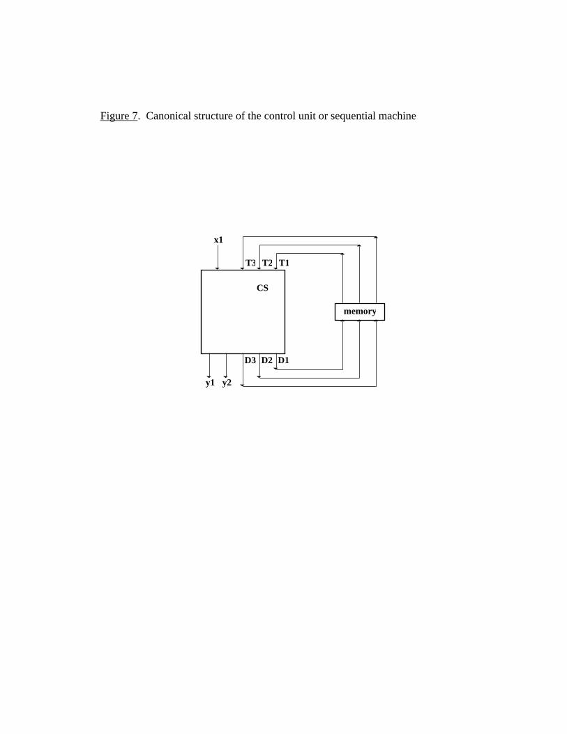
Figure 7. Canonical structure of the control unit or sequential machine
T1T2T3
D1D2D3
memory
x1
y1 y2
CS

Figure 8. EPROM Implementation for the “line-seeker” device.
X0101010101010101
T10000000011111111
T20000111100001111
T30011001100110011
Y111
Y2
1
R1
1
S1
1
R2 S2
1
1
R3
1
1
S311
1
Rs3 Rs2 Rs1
programmable OR array
fixed AND array

Figure 9. Ladder diagram description for the “line-seeker” device.
T1' T2' T3'
T1
T2
T3
X
X'
R1
R2
R3
S1
S2
S3
Y1
Y2
S3
R3
S2
T2' T3' X
T3 X'
T3 X
S1
T1
R1 T1
S2
T2
T3
S3 R3
T2
T3

Figure 10. Comparison between the programming and design control paradigms.
programming paradigm
(software-centered)
design paradigm
(hardware-centered)
Controller defined device for performing thecontrol program
collection of logical unitsembodying control
main construct algorithm state machine
control process implementation of the controlalgorithm
input/output transformations
learning activity programming design
learning outcome program logical circuit or scheme
methodology software engineering methods automaton synthesis methods

Figure 11. Main screen of the Controlled Systems Laboratory (CSL) learning
environment.
Behavior
logical scheme
y1x
File Edit Layout View Options Constructs Interface Tools
begin
flow-chart
ladder diagram
T1' T2' T3' Y1
T3 X'
X
S3
S2
R3
S3
X
T3'T2'T1
state-graph
a1
a2
a3a4
a5x1
x1x1
x1 x1
y1
y2
x1
x1
x1
y0
y0y0
y0
y0
y0 1
y0