Embed Size (px)
Citation preview

*Corresponding authors.
Email address:[email protected] (Jianqiao Ye)
A multi-scale model for studying failure mechanisms of
composite blades
Junjie Ye1,2, Chenchen Chu1, Heng Cai1, Xiaonan Hou2, Baoquan Shi1, Shaohua Tian3,
Xuefeng Chen3, Jianqiao Ye2,* 1Research Center for Applied Mechanics, Key Laboratory of Ministry of Education for Electronic Equipment
Structure Design, Xidian University, Xi’an 710071, China 2Department of Engineering, Lancaster University, Lancaster LA1 4YW, UK 3State Key Laboratory for Manufacturing Systems Engineering, Xi’an Jiaotong University, Xi’an 710049, China
Abstract
Composite structures have been widely used in wind turbine equipment for their high stiffness
to mass ratio and high strength. A major concern in the use of composite materials is their
susceptibility to various micro damage, such as fiber breakage and matrix crack, which will lead
to macroscopic structural fracture. In this paper, a multi-scale modeling strategy is proposed to
investigate failure mechanisms and damage evolution of composite blades with initial defects
from microscopic damage (including fiber fractures and matrix cracks) to macroscopic fracture.
At the microscopic scale, an isoparametric micromechanical model is developed to calculate
microscopic stresses and simulate microscopic damage. At the laminar scale, the classic laminate
theory is employed to evaluate the laminate stiffness. At the structural scale, a reverse modeling
technology is proposed to accurately acquire structural dimensions of a wind turbine blade, and a
macroscopic 3D model is implemented into ANSYS/LS-DYNA software. By comparing with the
experimental data, it is demonstrated that the proposed multi-scale method is suitable to predict
mechanical properties of complex composite structures effectively.
Keywords: Multiscale model, Wind turbine blade, Composites, Damage evolution, FBG
sensors.
1. Introduction
As one of the most abundant renewable and green resources, wind energy is increasingly
playing an important role in reducing CO2 emission for environmental protection and has viable
commercial values [1-3]. It has been one of the most important new energies due to its availability
and accessibility. To maximize the energy that can be harvested from wind, an efficient and safe
design of a wind turbine, including its strength and damage tolerance, is essential. Complex
dynamic loads may lead to a catastrophic failure of wind turbine blades [4-5]. According to the
data from Caithness windfarm information forum [6], blade failure is the most common accident
of wind turbines, estimated at around 3800 incidents per annum. Therefore, it is crucial for
researchers to have a better understanding of the failure mechanisms, which will improve the
safety and reliability of wind turbines.
Wind turbine blades, which are normally manufactured by continuous glass fiber-reinforced
resin matrix composites, accounts for nearly one-fifth of the cost of a wind turbine. Experimental
[7-8] and theoretical methods [9-10] have been used to investigate the mechanical features and
damage mechanisms of composite blades. However, for a heterogeneous material, it is difficult to
reveal the intrinsic relations between its macroscopic and microscopic characteristics, such as
fiber arrangements and fiber shape [11-14], by experimental methods. As a result, more and more
researchers are using numerical methods to study their mechanical properties and optimally design
2
composite wind turbine blades. Haselbach et al. [15] studied ultimate failure of a 34m long blade.
The numerical method the authors used shows good reliability and the obtained results agree well
with with the experimental results. Wu et al. [16] developed a GUI interface by using ANSYS to
construct a composites blade for stress analysis. The blade skin was designed using the maximum
principal stress failure criterion. Rafiee et al. [17] built a 3D finite element model and constructed
an iterative fluid-structure interaction approach for investigating aeroelastic behavior of a
full-scale composite wind turbine blade. It was concluded that general finite element models for
studying composite wind turbine blades were not computationally efficient as a large number of
finite elements had to be used. To improve the efficiency, Shah and Tarfaoui [18] proposed a
sub-modeling technique to reduce a large finite element model to a more manageable size.
Additionally, failure modes of composites (fiber fracture, matrix crack, etc) are much more
complex in comparison with those of homogeneous materials. These failure modes may occur
concurrently and at different scales, thereby requiring an integrated multiscale view of the damage
evolution starting from initiation, propagation and final structural failure. However, it is difficult
for the traditional finite element method to capture all the above events.
Multi-scale methods can be used to capture fine defects and internal cracks in a material and
reveal damage evolutions from microscopic damage to macroscopic fracture. Different
microstructures and damage modes can be effectively simulated by employing different theories
and methods due to the flexibility of multi-scale modeling framework [19-20]. In order to have a
better understanding of composite failures, multi-scale methods were proposed to investigate
micro/macro-mechanical responses, viscoelastic deformation, failure analysis of composite
materials [21-23]. Li and Cui [24] presented a multi-scale analysis method for calculating Yong’s
modules and Poisson’s ratios of composites with random short fiber distributions. Cai and Sun [25]
investigated viscoelastic deformations of 3D composites. The results from the multi-scale method
agreed well with the experimental results. Moreover, the influence of microscopic structural
parameters on viscoelastic properties was studied in details. Calneryte and Barauskas [26]
proposed a hierarchical multi-scale approach for studying large displacement, material
non-linearity and failure of composites. Zhou et al. [27] proposed a stochastic homogenization
method, which coupled with multi-scale homogenization and stochastic finite element methods, to
predict effective elastic properties of textile composites. The results showed that the method was
sufficiently accurate to acquire elastic properties of the composites. Greco et al. [28] proposed a
two-scale finite element continuum approach that was used to compute macroscopic load
deflection relationship and predict microscopic local failures. Muliana [29] presented a
computational multi-scale model for investigating thermo-viscoelastic responses of spherical
particle reinforced polymer matrix composites. Both mechanical and thermal properties of the
reinforced particles and polymer matrix were allowed to change with temperature and stress fields.
Han et al. [30] employed a hierarchical multi-scale simulation to study thermal residual stresses at
microscopic scale and its influences on the strength of composites at macroscopic scale. It
revealed that failure modes with and without thermal residual stresses were distinctively different.
In regard to applications in turbine blade design, a comprehensive review on damage evolution of
wind turbine blades was conducted by Montesano et al. [31], who developed a multi-scale
progressive damage model for evaluating sub-critical damage evolution and stiffness degradation
of blade structures. The ability of the model to predict the damage was demonstrated by the
quasi-static and fatigue simulation results. However, the analyses mentioned above are limited to
3
investigate progressive damages at structural level. For composites, due to their multiphase
structures, it is critical for researchers to reveal multiscale failures of individual constituent
materials.
Macroscopic fractures of composite structures are results of microscopic damages. In order to
reveal failure mechanisms of composite blades from microscopic damages to macroscopic
fractures, a three-scale numerical model is proposed in this study. To verify the proposed method,
strain test results acquired by Fiber Bragg Grating (FBG) sensors, which are mounted in the
spanwise direction of the composite blades, are employed. Moreover, damage evolutions of
reinforced fibers and matrix materials are also investigated. The detailed procedures of the
multi-scale modeling, experimental tests and prediction of damage evolutions are explained in the
following sections.
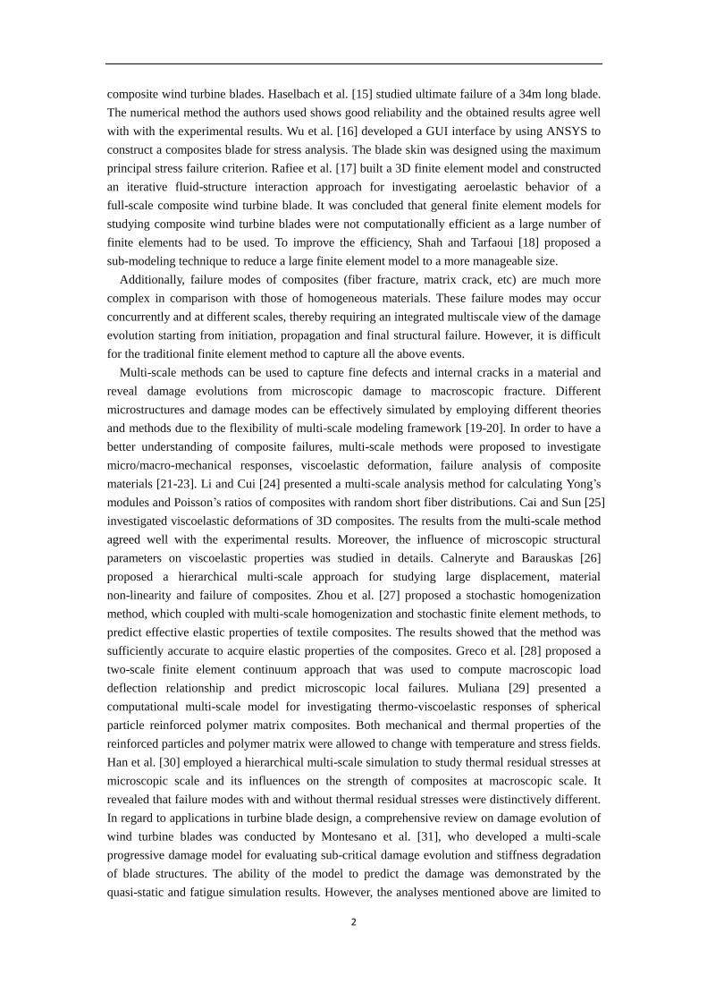
2. The multiscale modeling framework
In general, composite blades are composed of thermosetting resin and glass fibers, which are
manufactured by manual fiber placement and resin injection technology. The section profile of a
composite blade can be considered as a series of laminas with 0 fiber reinforcement [20, 32]. A
three-scale method, where macroscopic and microscopic models are coupled first to take
advantage of their efficiency and accuracy, respectively, is proposed to investigate the failure
mechanisms and damage evolutions of composite blades, as illustrated in Fig. 1. At the
microscopic scale, the finite-volume direct averaging micromechanics (FVDAM) theory is used to
evaluate the relations between the microscopic structural parameters and the stress-strain
properties of the composites. At the laminar scale, the laminate theory is employed to evaluate the
stiffness of laminate. A full scale 3D wind turbine blade is stimulated then at the structural scale
by ANSYS/LS-DYNA. In order to validate the proposed multi-scale method, the stress-strain
curves of a wind turbine blade in the spanwise direction are compared with those from
experiments acquired by FBG sensors. The proposed modeling framework is further developed to
investigate damage evolutions of the turbine blades by incorporating microscopic damage
mechanics, by which the user-defined subroutine of ANSYS/LS-DYNA is utilized to acquire the
microscopic stress field. Thus, the damage evolution and constituent failure of wind turbine blades
can be further studied. Detailed discussions on damage modeling and failure analysis are finally
presented.
3. Multi-scale modeling procedure
3.1. Microscopic modeling of the RVE
In order to analyze microscopic failures of composites, it is important to choose an effective
micromechanical method. By employing continuity conditions of sub-cell displacements and
stresses, the Generalized Method of Cells (GMC) was proposed by Aboudi [33-34]. The method
has been widely used in calculating stiffness matrix, mechanical behavior, as well as microscopic
stress fields of composites.
To predict mechanical behaviors of composites accurately, it is critical to define a proper
representative volume element (RVE). Compared with overall dimension of a composite structure,
the size of the RVE must be sufficiently small. Moreover, the RVE must contain enough
information and volume to represent the essence of the microscopic structure. It should be noted
that in reality fibers are always randomly distributed in matrix materials [22]. However, in order to

4
simplify the microscopic model, fibers are considered to be periodically distributed in the matrix
materials, and a real composite structure is composed of many of the RVEs. In the procedure of
microscopic modeling, a RVE is further divided into sub-cells as shown in Fig. 1(a), where and
indicate the serial number of each sub-cell. The dimensions of the RVE in the2y and
3y
directions are expressed, respectively, as:
1
N
H h
1
N
L l
(1)
where H and L are dimensions of the RVE as shown in Fig. 1(a). h and l are sub-cell
dimensions in the 2y and
3y directions, respectively.
To improve computational efficiency and accuracy, the GMC was further developed by other
researchers [35-36]. By employing the sub-cell stresses as unknown variables, Pindera and
Bednarcyk [37] improved calculation efficiency of the microscopic method. In order to further
improve the calculation accuracy and solve the sub-cell stress concentrations between inclusions
and matrix, an isoparametric element approach was proposed [9, 38]. The relation between the
mapping sub-cells in coordinate system and the sub-cells in coordinate system 2y -
3y is
given as follows [13]:
1, 2, 3, 4,( )
1 2 3 4( , ) ( , ) ( , ) ( , ) ( 2,3)k k k kk
i i i i iy N y N y N y N y i (2)
where 1
1( , ) (1 )(1 )
4N 2
1( , ) (1 )(1 )
4N 3
1( , ) (1 )(1 )
4N
4
1( , ) (1 )(1 )
4N . The superscript, k , denotes serial number of each sub-cell.
Superscripts 1-4 are surface numbers of each isoparametric element.
Here, the surface-averaged displacements 'ˆiu and the surface-average tractions
i ij jt n for
the thk sub-cell are proposed in the FVDAM theory to substitute the sub-cell displacements in
the GMC. ij and
jn are stress components and unit normal vectors, respectively. The
relationship between the two co-ordinate systems is
( )( )
2
3
kk
ii
ii
uu
y
uu
y
J (3)
where
32
32
yy
yy
J is the Jacobi matrix. For the thk sub-cell, displacement functions ( )
i
ku
can be written in the reference coordinate system , as,
( ) ( ) ( ) ( ) 2 ( ) 2 ( )
(00) (10) (01) (20) (02)
1 1ˆ (3 1) (3 1)
2 2
k k k k k k
i i i i i iu W W W W W (4)
5
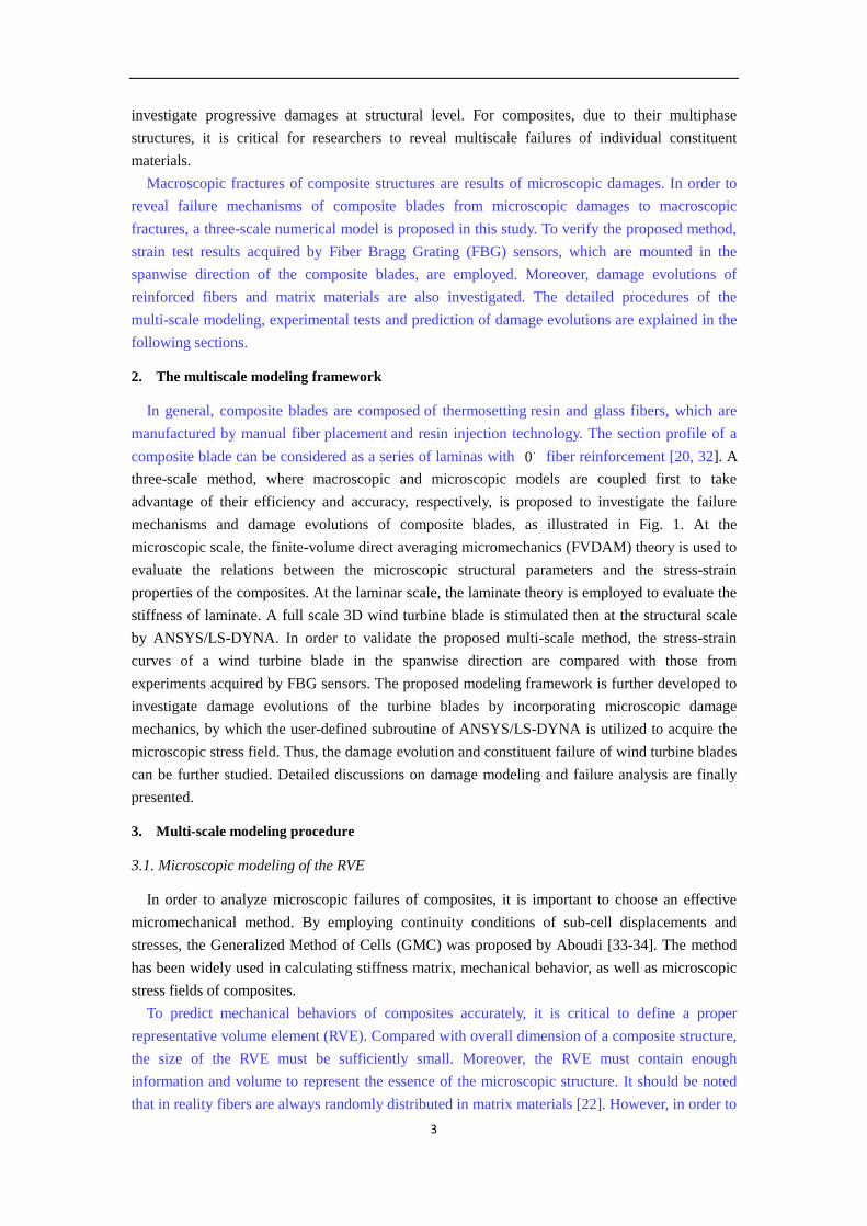
where ( )
(00)
k
iW and ( )
( ) 0, 0k
i mnW m n ( ) are the surface-averaged partial derivatives of the thk
sub-cell displacements.
The relationship between the surface-averaged tractions and the surface-averaged displacements
can be expressed as follows: 1 pl plˆ ˆ ' t NC AΒu ANΦ Z Nσ (5)
where (1) (2) (3) (4)ˆ ˆ ˆ ˆ ˆ T
t t t t t , (1) (2) (3) (4) T
N n n n n , (1) (2) (3) (4)ˆ ˆ ˆ ˆ ˆ u u u u u . Detailed
expressions of A and Β can be found in Khatam [38]. The parameter, plσ , which is
determined by matrix plastic deformations, is related to material plastic stress.
To calculate global stiffness matrix globalK of continuous fiber-reinforced composites,
continuity conditions of interfacial traction and displacement across adjacent sub-cells, together
with periodic boundary conditions, are imposed. Thus, the following stiffness equation is obtained.
The unknown surface-averaged displacements U is acquired by the global stiffness matrix
globalK , that is
1
global global global
U K Cε Γ G (6)
Where, U is the unknown surface-averaged displacement; ε is the strain component. C
contains the sub-cell local stiffness matrix. globalΓ and
globalG are related to temperature
variations and inelastic properties of the constituent materials.
3.2 Macro modeling of composite laminates
Composite laminates are composed of a serial of laminas. The classic laminate theory calculates
the internal in-plane forces 1 1 2 2 1 2
T
x x x x x xN N N and the internal moments
1 1 2 2 1 2
T
x x x x x xM M M
by the following equations [39]:
1 1 1 1
3
2 2 2 23
1 2 1 2
( )
( 1)1
( )
x x x xN x k
k
x x ij x xx k
k
x x x x
N
N C dz
N
(7)
1 1 1 1
3
2 2 2 23
1 2 1 2
( )
( 1)1
( )
2
x x x xN x k
k
x x ij x xx k
k
x x x x
M
M C z dz
M
(8)
where 1 1 2 2 1 2
T
x x x x x x denote strain components in the
1 2x x coordinate system, as shown
in Fig. 1(b). ( )( ) k
ijC and z are the stiffness matrix and thickness coordinate of the thk lamina,
respectively.

6
The in-plane strain components can be calculated by
1 1 1 11 1
2 2 2 2 2 2
1 2 1 2 1 2
0 0
0 0
0 02 2 2
x x x xx x
x x x x x x
x x x x x x
k
z k
k
(9)
where 1 1 2 2 1 2
0 0 0 2T
x x x x x x are the mid-surface strains of each lamina.
1 1 2 2 1 2
0 0 0 2T
x x x x x xk k k are the
mid-surface curvature and twist.
Substituting Eq. (9) into Eq. (7) and Eq. (8), the equilibrium equation of a composite laminate
can be expressed in matrix form as,
1 1
2 2
1 2
1 1
2 2
1 2
11 12 13 11 12 13
21 22 23 21 22 23
31 32 33 31 32 33
11 12 13 11 12 13
21 22 23 21 22 23
31 32 33 31 32 33
x x
x x
x x
x x
x x
x x
N A A A B B B
N A A A B B B
N A A A B B B
M B B B C C C
B B B C C CM
B B B C C CM
1 1
2 2
1 2
1 1
2 2
1 2
2
2
x x
x x
x x
x x
x x
x x
(10)
where the elements in equation (10) are calculated by:
1
1
( ) ( )N
k
ij ij k k
k
A C z z
2 2
2 1
1
1( ) ( )
2
Nk
ij ij k
k
B C z z
3 3
2 1
1
1( ) ( )
3
Nk
ij ij k
k
C C z z
(11)
3.3 Macroscopic modeling of wind turbine blade
3.3.1 Experimental instrument
In order to study failure mechanisms and damage evolution of composite structures, a wind
turbine blade with initial damage is considered, as shown in Fig. 1(c). Due to the complex
geometric profile, it is difficult to construct a 3D model using CAD. In order to precisely acquire
actual structure parameters of the wind turbine blade, a nonparametric modeling technology based
on the reverse engineering is proposed in this study. The experimental equipment includes 3D
scanner MetraSCAN and Creaform C-Track as shown in Fig. 2. The laser scanner MetraSCAN
can measure an area of 275 250 mm each time with an error tolerance of 0.03mm, and record
480000 points per second. The Creaform C-Track system is used to establish a virtual global
coordinate system. Software, Vxinspect and Geomagic Studio, are used to process the data to
construct accurate 3D blade models.
3.3.2. Digital modeling of the wind turbine blade
Detailed procedures of the digital modeling of wind turbine blade can be divided into four
steps:
(1) Presetting of a measurement system. In order to acquire an accurate 3D model, the wind
turbine blade is firstly placed on a platform. The C-Track system, a trilinear coordinate
measuring instrument, is fixed to the ground. There must be no obstacle between the

7
camera of the C-Track system and the wind turbine blade.
(2) Acquisition of point clouds. A virtual global coordinate system created by the C-Track
system, is employed to track the wind turbine blade, and connect to the scanner,
MetraSCAN. Due to the limited measuring area of 275 250 mm, multi-view point clouds
are acquired by the Vxinspect software through moving the MetraSCAN scanner around
the wind turbine blade, as shown in Fig. 3.
(3) Data processing of point clouds. Originally scanned point clouds may contain noises or
redundancies as shown in Figs. 3(c)-(d). In order to overcome these problems, point clouds
are firstly feed into the processing software, Geomagic Studio, to remove noises. Secondly,
multi-view point clouds are used to remove redundancies. After the above modifications, a
clean, nonoverlapping and smooth point cloud model is obtained.
(4) Surface reconstruction. The processed point cloud model is imported into the Geomagic
Studio to reconstruct a fine 3D model. Firstly, the point cloud model is wrapped into a grid
model. Secondly, the grid model is further modified by hole filling and remeshing, etc.
Finally, on the basis of the mesh model, a smooth surface model is developed by using
non-uniform rational B-splines (NURBS) surface fitting technique, as shown in Fig. 4.
To complete the NURBS surface fitting, the cloud data are further reduced according to
accuracy requirements. The interpolation function P of the free-form surface can be written as:
1 1
, ,
1 1
( , ) ( ) ( )m n
ij i p j q
i j
P u v p N u N v
(12)
where ijp donate the control points. , ( )i pN u and , ( )j qN v are the base functions along the u
and v directions, respectively, as shown in Fig. 3(b).
The control points ijp , which are related to weighting factors ijw , can be expressed as [40]
1 1
, ,
1 1
1 1
, ,
1 1
( ) ( )
( , )
( ) ( )
m n
ij ij i p j q
i j
ij m n
ij i p j q
i j
w d N u N v
p u v
w N u N v
(13)
It should be noted that the free-form surface with a higher accuracy will be generated when the
weighting factors ijw are introduced in the interpolation function.
4. Model validation
4.1. Model errors and mesh convergence
4.1.1. Error evaluations of the geometry of the composite blade
The digital geometric profile of the wind turbine blade developed by the MetraSCAN system is
shown in Table 1. It can be seen that the measured length and width of the composite blades is
84.5cm and 16.3cm, respectively. For the composite blades, the 3D scanner MetraSCAN can
measure an area of 275 250 mm each time with an error tolerance of 0.03mm. It is indicated that
the error derived from experimental equipment is acceptable. In order to estimate the accuracy of
CAD model reconstruction, the distances between the NURBS surface and point cloud data from

8
the 3D scanner MetraSCAN are compared by employing the Imageware software as shown in Fig.
5. The red surface in Fig. 5(a) shows that the distance errors between the point cloud data and the
NURBS surface can be ignored, and the maximum error, located around the blade tip, is 52.98 10 mm (as shown in Fig. 5(b)).
4.1.2. Mesh convergence investigations
In this study, 3D FE models with 2212 elements and 65690 elements are used to study mesh
sensitivities. The distance between the loading location and the blade tip is 40 mm, and the blade
is clamped at the root. The models are subjected to the displacement loadings. Von Mises stresses
at four locations, i.e., pt1, pt2, pt3 and pt4, as shown in Fig. 6(a) are compared in Fig. 7. It can be
seen that the 3D composite blade model with 2212 elements is sufficiently accurate.
4.2. Comparisons of mechanical properties
4.2.1. Constituent material parameters
The wind turbine blade investigated in this paper is manufactured by E-glass/resin composites.
The E-glass fibers are continuously distributed in the matrix. Based on the microscopic images
from a transmission electron microscopy test, it is assumed that the fibers are of circular section
and periodically distributed in the matrix material. The material parameters of the composite are
presented in Table 2, showing that the fibers are transversely isotropic, and the matrix is isotropic.
4.2.2. Load-strain relation
In order to validate the proposed multi-scale model, Fiber Bragg Gratings (FBG) sensors are
mounted in the spanwise direction of the blade to acquire real-time strains. Locations of the FBG
sensors are labeled as A1-A4 and B1-B4, as shown in Fig. 6(a). It should be noted that a circular
hole of 13mm located at middle of the chord line and 175mm away from the blade root, presents
as an initial defect. To measure stress concentrations, sensors A1 and B1 are located near the
initial damage. The strain measurement system is composed of a SM130-700 demodulator, FBG
sensors and PC, as shown in Fig. 8. In the experiment, six different loads (1.8kg, 2.8kg, 3.8kg,
4.8kg, 5.1kg and 7.1kg) are applied to the blade tip as shown in Fig. 6(a).
It should be noted that variations of the loadings will lead to strain changes at the measured
positions. Accordingly, central wavelengths of the FBG sensors will shift. In order to avoid the
wavelength aliasing, FBG sensors with eight different central wavelengths are employed, as
shown in Table 3. The relationship between the central wavelengths of the FBG sensors and the
measured strains can be written as:
01000 1000BB
e eP P
(14)
where B is variation of central wavelength.
B and 0 are current and original wavelength
of the FBG sensors, respectively. The conversion coefficient eP is taken as 1.2 /pm in the
experiment.
Figs. 9(a)-(b) present the measured strains relative to the spanwise locations. For comparisons,
strain responses of the blade subjected to the six static loads are considered. It is no doubt that the
initial damage reduces load carrying capacity of the blade, and stress concentration occurs near the
damage. From the tested results, it is interesting to notice that the strain increased first and then
decreased in the spanwise direction. The maximum strains are located at A2 and B2, whose
locations are 290mm away from the fixed end. This is due to the complex curved surface of the
9
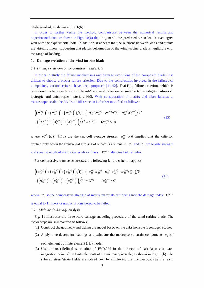
blade aerofoil, as shown in Fig. 6(b).
In order to further verify the method, comparisons between the numerical results and
experimental data are shown in Figs. 10(a)-(b). In general, the predicted strain-load curves agree
well with the experimental data. In addition, it appears that the relations between loads and strains
are virtually linear, suggesting that plastic deformation of the wind turbine blade is negligible with
the range of loading.
5. Damage evolution of the wind turbine blade
5.1. Damage criterion of the constituent materials
In order to study the failure mechanisms and damage evolutions of the composite blade, it is
critical to choose a proper failure criterion. Due to the complexities involved in the failures of
composites, various criteria have been proposed [41-42]. Tsai-Hill failure criterion, which is
considered to be an extension of Von-Mises yield criterion, is suitable to investigate failures of
isotropic and anisotropic materials [43]. With consideration of matrix and fiber failures at
microscopic scale, the 3D Tsai-Hill criterion is further modified as follows:
2 2 22 2
11 22 33 11 22 11 33 22 33
2 2 22 ( )
12 13 23 22 ( 0)
t tY Y
T D
(15)
where
( , 1,2,3)ij i j
are the sub-cell average stresses. 22 0
implies that the criterion
applied only when the transversal stresses of sub-cells are tensile. tY and T are tensile strength
and shear strength of matrix materials or fibers. ( )D denotes failure index.
For compressive transverse stresses, the following failure criterion applies:
2 2 22 2
11 22 33 11 22 11 33 22 33
2 2 22 ( )
12 13 23 22 ( 0)
c cY Y
T D
(16)
where cY is the compressive strength of matrix materials or fibers. Once the damage index ( )D
is equal to 1, fibers or matrix is considered to be failed.
5.2. Multi-scale damage analysis
Fig. 11 illustrates the three-scale damage modeling procedure of the wind turbine blade. The
major steps are summarized as follows:
(1) Construct the geometry and define the model based on the data from the Geomagic Studio.
(2) Apply time-dependent loadings and calculate the macroscopic strain components ij of
each element by finite element (FE) model.
(3) Use the user-defined subroutine of FVDAM in the process of calculations at each
integration point of the finite elements at the microscopic scale, as shown in Fig. 11(b). The
sub-cell stress/strain fields are solved next by employing the macroscopic strain at each

10
integral point.
(4) Apply failure criteria to identify failures of matrix or fibers. Once one of failure criteria in
Eqs. (15)-(16) is satisfied, the sub-cell stiffness will degenerate to 1% of the original value.
In addition, the macroscopic stiffness matrices and the stresses of each finite element are
calculated using the homogenization method.
(5) Repeat the above calculations for next loading level and identify newly failed elements.
The multi-scale progressive damage analysis terminates once total failure of the blade
occurs.
5.3 Matrix damage evolution in wind turbine blade
Fig. 12 shows damage evolution on the upper surface of the blade using the above validated
multi-scale model. In general, it can be seen that matrix damage appears first at the blade root and
spreads further in the spanwise direction. With the increase of external loadings, damages are
found near the hole. In details, when the external load is equal to 11.96kg, a minor matrix damage
is found at the blade root as shown in Fig. 12(a). It means that the stresses at the blade root are
greater than those around the hole. When the external loading is increased to 17.14kg as shown in
Fig. 12(b), a minor matrix damage is found near the hole. When the external load is equal to
23.12kg as shown in Fig. 12(d), the matrix damage are further extended around the hole and the
blade root. Furthermore, matrix damage also starts to appear in the leading edge. When the
external load is 31.05kg (Fig. 12(e)) or 33.7kg (Fig. 12(f)), it can be seen that new matrix damage
are located at the trailing edge near the initial damage.
Fig. 13 shows damage evolutions on the lower surface of the blade subjected to compressive
loadings. When the external load increases to 30.69kg as shown in Fig. 13(a), compressive matrix
failure occurs at the leading edge of the blade near the root. When the external load is 33.07kg as
shown in Fig. 13(b), compressive matrix damage is found at the trailing edge and the tip of the
blade. In addition, it is noticed that compressive damage are further accumulated along the blade
edge.
5.4 Fiber damage evolution in the wind turbine blade
Fig. 14 shows the fiber damage evolution relative to the external loads. Initial fiber damage at
the blade root is found at a load of 20.39kg, as shown in Fig. 14(a). The fiber failures are due to
the coupled matrix damages and stress concentrations at the blade root. As the external load
increases, further fiber damage accumulate in the spanwise direction, as shown in Fig. 14(b).
However, no evident fiber damage is found near the circular hole. From Fig 12 (c)-(f), it can be
found that severe matrix damage occurs when the external load is equal to 20.89kg. This severe
matrix damage is caused by fiber fracture. The failure of the fibers results in stress concentrations
in the matrix materials around the fractured fibers, which accelerates matrix failures.
6. Conclusions
In this study, a generalized multi-scale model was developed to investigate damage evolutions
of a composite blade. The proposed multi-scale model included analyses at microscopic, laminar
and structural scales. The microscopic model was used to acquire microscopic stress fields of the
representative volume element. In order to describe microscopic damage, microscopic failure
criteria were introduced and employed. In addition, a reverse technology was employed to acquire
actual structure parameters of the wind turbine blade. By comparing with the experimental results,
it was concluded that the proposed multi-scale method could be used to effectively predict
11
mechanical properties of complex composite structures.
The validated model was used then to simulate damage evolution of a wind turbine blade with
an initial damage. The numerical results revealed that matrix damage appeared first in the blade
root on the upper surface, and developed further in the spanwise direction. With further increasing
of the external load, matrix compressive failures were found near the leading edge and the root of
the blade’s lower surface. In addition, initial fiber damage appeared first near the blade root. The
fiber damage also developed further in the spanwise direction.
Future research on failures due to delamination is required. Studies on the coupling effect of
microscopic and macroscopic delaminations are also recommended.
Acknowledgments
This work was supported by the National Natural Science Foundation of China (No. 51675397,
51605365). The National Natural Science Foundation of Shaanxi Province (No. 2018JZ5005).
China Scholarship Council (No.201706965037). Fundamental Research Funds for the Central
Universities (No.JB180414). The 111 Project (No. B14042). The first author is also grateful to the
Engineering Department, Lancaster University for the support he has received during the course of
his visit.
References
[1] Varna J, Talreja R. Integration of macro- and microdamage mechanics for the performance
evaluation of composite materials. Mech Compos Mater 2012; 48(2): 145-160.
[2] Chen N, Wang Q, Yao LZ, Zhu LZ, Tang Y, Wu FB, Chen M, Wang NB. Wind power
forecasting error-based dispatch method for wind farm cluster. J Mod Power Syst Clean
Energy 2013; 1(1):65-72.
[3] Eder M. A, Bitsche RD, Belloni F. Effects of geometric non-linearity on energy release rates
in a realistic wind turbine blade cross section. Compos Struct 2015; 132: 1075-1084.
[4] Pawar MJ, Amar P, Ravindra N. Experimental investigation and numerical simulation of
granite powder filled polymer composites forwind turbine blade: a comparative analysis.
Polym Compos 2017; 38(7): 1335-1352.
[5] Wang Y, Zhupanska OI. Lightning strike thermal damage model for glass fiber reinforced
polymer matrix composites and its application to wind turbine blades. Compos Struct 2015
132: 1182-1191.
[6] Summary of Wind Turbine Accident data to 30 June 2018.
http://www.caithnesswindfarms.co.uk/AccidentStatistics.htm
[7] Zeng J, Song BL. Research on experiment and numerical simulation of ultrasonic de-icing
for wind turbine blades. Renew Energ 2017; 113: 706-712.
[8] Kim C, Kim K, Kim H, Paek I, Yoo N, Nam Y, Campagnolo F, Bottasso C. Method to
estimate bending moments acting on a wind turbine blade specimen using FBG sensors. In J
Precis Eng Man 2012; 13(7): 1247-1250.
[9] Jeong J, Park K, Jun S, Song K, Lee DH. Design optimization of a wind turbine blade to
reduce the fluctuating unsteady aerodynamic load in turbulent wind. J Mech Sci Technol
2012; 26 (3): 827-838.
[10] Dai JC, Hu YP, Liu DS, Long X. Calculation and characteristics analysis of blade pitch loads
forlarge scale wind turbines. Sci China Technol Sci 2010; 53(5): 1356-1363.
[11] Meng Q, Wang Z. Prediction of interfacial strength and failure mechanisms in
particle-reinforced metal-matrix composites based on a micromechanical model. Eng Fract
12
Mech 2015; 142: 170-183.
[12] Ye JJ, Qiu YY, Chen XF, Ma J. Initial and final failure strength analysis of composites based
on a micromechanical method. Compos Struct 2015; 125: 328-335.
[13] Ye JJ, Qiu YY, Chen XF, Zhai Z, Huang CL, Zhang XL. Numerical Investigations of
Microscopic Characteristic Influences on the Mechanical Properties of Polymer-Matrix
Composites. Polym Compos 2017; 38(12): 2734-2742.
[14] Ye JJ, Cai H, Wang YK., Jing Z, Shi BQ, Qiu YY, Chen XF. Effective mechanical properties
of piezoelectric–piezomagnetic hybrid smart composites. J Intel Mater Sys Struct 2018; 29(8)
1711-1723.
[15] Haselbach PU, Branner K. Initiation of trailing edge failure in full-scale wind turbine blade
test. Eng Fract Mech 2016; 162:136-154.
[16] Wu WH, Young WB. Structural analysis and design of the composite wind turbine blade.
Appl Compos Mater 2012; 19(3-4): 247-257.
[17] Rafiee R, Tahani M, Moradi M. Simulation of aeroelastic behavior in a composite wind
turbine blade. J Wind Eng Ind Aerod 2016; 151:60-69.
[18] Shah OR, Tarfaoui M. The identification of structurally sensitive zones subject to failure in a
wind turbine blade using nodal displacement based finite element sub-modeling. Renew
Energ 2016; 87:168-181.
[19] Meng Q, Li B, Li T, Feng XQ. Effects of nanofiber orientations on the fracture toughness of
cellulose nanopaper. Eng Fract Mech 2018; 194:350-361.
[20] Zhai Z. Multiscale modeling based on generalized cell of method and its application in
composite structural health monitoring. Xi’an Jiaotong University, 2014.
[21] Meng Q, Li B, Li T, Feng XQ. A multiscale crack-bridging model of cellulose nanopaper. J
Mech Phys of Solids 2017; 103: 22-39.
[22] Ye JJ, Chu CC, Wang YK, Qiao XJ, Zhai Z, Chen XF. A multi-scale modeling scheme for
damage analysis of composite structures based on the High-Fidelity Generalized Method of
Cells. Compos Struct. 2018; 206: 42-53.
[23] Kanouté P, Boso DP, Chaboche JL, Schrefler BA. Multiscale Methods for Composites: A
Review. Arch Comput Methods Eng. 2009; 16: 31-75.
[24] Li YY, Cui JZ. The multi-scale computational method for the mechanics parameters of the
materials with random distribution of multi-scale grains. Compos Sci Technol 2005; 65(9):
1447-1458.
[25] Cai Y, Sun H. Prediction on viscoelastic properties of three-dimensionally braided
composites by multi-scale model. J Mater Sci 2013; 48(19): 6499-6508.
[26] Calneryte D, Barauskas R. Multi-scale evaluation of the linear elastic and failure parameters
of the unidirectional laminated textiles with application to transverse impact simulation.
Compos Struct 2016; 142:325-334.
[27] Zhou XY, Gosling PD, Pearce CJ. Perturbation-based stochastic multi-scale computational
homogenization method for woven textile composites. Int J Solids Struct 2016; 80:368-380.
[28] Greco F, Leonetti L, Lonetti P. A two-scale failure analysis of composite materials in
presence of fiber/matrix crack initiation and propagation. Compos Struct 2013;
95(95):582-597.
[29] Muliana AH. Multi-scale framework for the thermo-viscoelastic analyses of polymer
composites. Mech Res Commun 2007; 35(1):89-95.
[30] Han G, Guan Z, Li Z, et al. Multi-scale modeling and damage analysis of composite with
thermal residual stress. Appl Compos Mater 2015; 22(3):289-305.
[31] Montesano J, Hao C, Singh CV. Development of a physics-based multi-scale progressive
damage model for assessing the durability of wind turbine blades. Compos Struct 2016;
141:50-62.

13
[32] Brndsted P, Nijssen RPL. Advances in Wind Turbine Blade Design and materials. Woodhead
Pub.; 2013.
[33] Aboudi J, Arnold SM, Bednarcyk BA. Micromechanics of composite materials-a generalized
multiscale analysis approach. Elsevier Science Pub. Ltd.; 2013.
[34] Ye JJ, Chen XF, Zhai Z, Li B, Zi YY, He ZJ. Effects of thermal stress and imperfect
interfacial bonding on the mechanical behavior of composites subjected to off-axis loading.
Mat Sci Eng A 2010; 527: 7530-7537.
[35] Tang Z, Zhang B. Prediction of biaxial failure envelopes for composite laminates based on
generalized method of cells. Compos Part B-Eng 2012; 43:914-25.
[36] Ye JJ , Hong Y, Wang YK, Shi BQ, Zhai Z, Chen XF. Thermal cycling influences on
compressive deformations of laminate composites. Polym Compos 2018; DOI: 10.1002/pc.
[37] Pindera MJ, Bednarcyk BA. An efficient implementation of the GMC Micromechanics mode
for Multi-phased materials with complex microstructures. NASA; 1997.
[38] Khatam H, Pindera M J. Parametric finite-volume micromechanics of periodic materials with
elastoplastic phases. Int J Plasticity 2009; 25(7):1386-1411.
[39] Huang ZM, Zhou YX. Strength of fibrous composites. Zhejiang University Press. 2011.
[40] Jung HB, Kim K. A new parameterisation method for NURBS surface interpolation. Int J Adv
Manuf Tech, 2000; 16(11): 784-790.
[41] Pandey A, Arockiarajan A. An experimental and theoretical fatigue study on macro fiber
composite (MFC) under thermo-mechanical loadings. Eur J Mech-A/Solids 2017; 66: 26-44.
[42] Talreja R. Assessment of the fundamentals of failure theories for composite materials.
Compos Sci Technol 2014; 105: 190-201
[43] Rahaeifard M, Ahmadian M T, Firoozbakhsh K. A strain gradient based yield criterion. Int J
Eng Sci 2014; 77: 45-54.0