Embed Size (px)
Citation preview

A Model Reference Adaptive PID Control for Electromagnetic ActuatedMicro-positioning Stage
Shunli Xiao1, Yangmin Li1,2,∗ and Jinguo Liu2
Abstract— This paper presents a model reference adaptivePID controller for controlling a novel compliant flexures-based XY micro-positioning stage driven by electromagneticactuators. The stage is specially designed by employing doublefour-bar parallelogram flexures and four non-contact electro-magnetic force actuators to realize the kinematic decouplingand force decoupling respectively. Based on preliminary openloop experiments and simple PID controller based close-loopexperiments, we found that the system is with typical hysteresisand nonlinear characteristics. As model reference adaptivecontrol techniques possess great advantages to tackle robustnessissues of nonlinear and model uncertainty systems, it is designedand adopted to control the micro-manipulator system. At first,a model reference adaptive PID controller design process isintroduced. Then control parameters are systematically tunedbased on intuitive desired performance and robustness. At last,experimental results verify the process for controlling the micro-positioning stage, which shows that the adopted controllercandrive the mobile stage to track the desired reference pathexactly.
I. I NTRODUCTION
Compliant mechanisms with flexure hinges can providewith very high precision in performing precise manipulationand assembly task, therefore they are widely applied inmicro/nano world. Replacing with conventional mechanicaljoints, flexure hinges can provide more ideal high-precisionmotions since they have advantages including no backlash,no friction losses, no need for lubrication, vacuum compat-ibility, ease of fabrication and basically no need for assem-bling. Many compliant mechanisms with flexural hinges canbe designed and fabricated to realize precise micro/nano-positioning tasks [1]- [4].
For more applications such as IC assembly or biologicalcell manipulation, a large motion range is preferred for eachmotion axis. In order to achieve both large motion range,high resolution in positioning, and simple controller design,considering the small payload of the maglev system in thenormal gravity environment, we need not only to construct akinematic decoupled structure with compliant flexure hinges,
This work was supported in part by National Natural Science Foundationof China (Grant No. 61128008), Macao Science and TechnologyDevel-opment Fund (Grant No. 016/2008/A1), and the State Key Laboratory ofRobotics of Shenyang Institute of Automation (Grant No. O8A120S).
S. Xiao is a Ph.D. Candidate with the1Department of ElectromechanicalEngineering, University of Macau, Taipa, Macao 999078, P. R. China.
Y. Li is an Overseas Distinguished Professor at the2State Key Laboratoryof Robotics of Shenyang Institute of Automation, Chinese Academy of Sci-ences, Shenyang 110016, China,∗Corresponding author: [email protected].
J. Liu is a Professor at the2State Key Laboratory of Robotics of ShenyangInstitute of Automation, Chinese Academy of Sciences, Shenyang 110016,China.
but also need to eliminate force contact by using non-contact or a frictionless force generated between the movingplatform and the stator. Several kinds of actuators can realizenon-contact or frictionless forces, such as electromagneticforce and air bearings, but air bearings are not suitable fora high vacuum environment. There are many advantagesassociated with electromagnetic actuators in terms of nocontamination, no friction, fast response, large travel range,and low cost [5]- [7]. Moreover, comparing with the maglevmicro positioning systems [8], the electromagnetic drivenmicro manipulator with flexure-based mechanism can havea large load capability as well as a good precision.
Although the compliant flexures based electromagneticactuators driven system possesses many advantages, thevarying air gap between the actuators and the armaturescauses severe nonlinear and hysteresis characteristics. Thenonlinear and hysteresis characteristics of the actuatorsbringmuch troubles to the control strategies. It is even hard fora normal PID controller to get a stable performance inthe whole working range. Some advanced control strategiesare necessary for the system. As the mechanical system isdecoupled, a single-input single-output(SISO) controller isenough for each direction of X and Y. For the decoupledsystem, the advantage is that the system can be modeledand measured in each direction separately. Since MRAC-PIDcontroller owns the ability of great robust characteristics fornonlinear, hysteresis and variable parameters systems, itisadopted in this research to control the plant.
II. D ESIGN AND MODELING OF THE DECOUPLEDXYCOMPLIANT STAGE
A. Design of The Decoupled XY Compliant Stage
As carefully studied in our previous work in [7], in orderto construct a decoupled XY compliant stage, a mechanismemulated from rigid system with double four-bar parallelo-gram flexures is employed due to its simple structure andease of manufacture. For a totally decoupled structure, oneaspect is the kinematic decoupling, the other one is the forcedecoupling. The designed mechanical system is driven byelectromagnetic actuators whose non-contact driven forcecan be used to cope with the function of force decoupling.The whole system can be shown in Fig.1. The mechanicalstructure is such simple that the entire mechanism systemcan be fabricated monolithically by wire electro-dischargemachining (WEDM). Aluminium alloy material (AL7075-T651) with a highσy/E ratio is selected as the materialto build the stage so that a large deflection is allowed.Associated with proper dimension, the motion range can
The Eighth Annual IEEE International Conference on Automation Science and Engineering (CASE), August 20-24, 2012, Seoul, Korea, pp.97-102

Fig. 1. 3D mechanical design of the manipulator
Fig. 2. Prototype of the mechanical system
reach±500 µm with ultrahigh precision which will havegreat demand in many micro/nano operations. After all, theadvantage of this stage is that it is easily fabricated, low cost,with large working range and heavy load ability. If properadvanced control algorithms are adopted, high resolution willbe realized.
III. FABRICATION AND PRELIMINARY EXPERIMENTAL
STUDY
After the mechanical structure is designed and the pa-rameters are optimized, the prototype can be fabricatedvia electro-discharge machining. The prototype is shownin Fig.2. In the experimental study, two laser displacementsensors(Microtrak II head model: LTC-025-02 from MTIinstrument,Inc.) with a resolution of0.12µ and linearitybetter than0.05% over a measurement range of2mmassociated with a dSPACE DS1005 (from dSPACE GmbH)rapid prototyping system equipped with DS2001 A/D andDS2102 D/A modular boards are employed to construct theexperimental setup. The power amplifier for the electromag-netic actuators is made through OPA548 which is a low-cost,high-voltage/high-current operational amplifier. It is operatedby either single(+8V to +60V) or dual power suppliers(4Vto 30V), which outputs high current 3A continuously and 5Aat peak. The connection scheme of the whole experimentalsystem can be observed in Fig.3.
Fig. 3. Experimental setup and the connection diagram
Fig. 4. Hysteresis loop in x direction
A. Open Loop Hysteresis Analysis
From the open loop control experiment, the hysteresisand the nonlinear characteristics of the system can be seenclearly. The maximum hysteresis rate can reach 11.5%. Thenonlinear characteristics of the system can be seen fromFig.4, at the beginning, the first 2 voltages can just movethe mobile stage 50 microns; the following 2 voltages from2 to 4 volts can lead to 130 microns displacement; the last2 volts can result in 300 microns. The slope is increasingaccording to the displacement of the mobile stage, in reality,it is related to the gap between the electromagnet andthe armature. Therefore, how to model the electromagneticactuators with variable gaps will be the key problems of thecontrol system. Since the electromagnetic actuators are withfast responsibility, when the input signal is within 10Hz, thehysteresis loops look almost with no differences.
B. Preliminary PID Study
After the nonlinear features of the electromagnetic actu-ators are analyzed, the PID controller will be tested in thesystem as it is the most widely used controller. After the PIDparameters are carefully tuned through engineering method,it can be seen from the Fig.5 that at the first step commandfrom 0 to 100µm, the response ascending so slowly indicatesthat the P gain of the PID parameters is obviously too small.But the following steps just used almost 4 seconds, 3seconds,and 2 seconds to reach the reference command which meansthe response is growing faster and faster when the armature
The Eighth Annual IEEE International Conference on Automation Science and Engineering (CASE), August 20-24, 2012, Seoul, Korea, pp.97-102

Fig. 5. Step response of preliminary PID control study
is closer and closer to the electromagnet. The last step showsclearly that the parameters can not suit for the system so thatthe system is becoming oscillating and unstable for the longrun. The experiment also shows clearly that the mechanicalsystem with electromagnetic actuator is not a linear system.Since the driving force is not only determined by the voltageor current applied to the electromagnet but also by thedistance between the armature and the electromagnet, thesystem is with serious nonlinear characteristics just as thepreliminary PID experiment shows. It is impossible to obtaina satisfy robust performance at the whole working rangeby using normal PID controller. Further experiments showthat even limited in a small displacement range, it is stillvery hard to obtain satisfy PID parameters because of theproblems of overshoot and response time. For that reasons,an advanced controller should be adopted.
IV. CONTROL STRATEGIES
As indicated in preliminary study, we realize that thesystem is with typical nonlinear and hysteresis characteris-tics. Then, a more advanced controller should be adopted.Although in the model reference adaptive controller (M-RAC), the desired index of performance is given by thereference model, and the controller can establish robust-ness with respect to bounded disturbances and unmodeleddynamics, it is hard to adjust the parameters to obtain agood performance, even worse it is very difficult to makethe system stable. From previous study, the PID controllercan be used to control the designed micro-positioning stagein different working range with different PID parameters.That is to say, the parameters of the PID controller needto be adjusted on-line automatically. Many ways can beused to tune the PID parameters, aiming for combining theadvantages of the MRAC and PID controller, the MRACPID controller is adopted in this research. With the aidof MATLAB Simulink Toolbox and dSPACE system, theadopted MRAC PID controller is very easy to implement.
A. System Identification
Although the system is with nonlinearity and typical hys-teresis characteristics, due to the great robust characteristicsand the self adaptive ability of the MRAC PID controller, anapproximated model of the system is needed for the design
Fig. 6. General structure of a typical MRAC scheme
Fig. 7. MRAC PID controller block diagram for the electromagneticactuated micro-positioning stage
of the control system [9]. The approximated model can beobtained through many methods. An analytical model of themechanical system with magnetic actuators was derived in[6]. In practice, the approximated model of the system canbe obtained by system identification method conveniently.
Even if the system is with great nonlinearity and hysteresisfeature, we can still use the system identification toolboxto obtain a approximated linearity auto-regression exoge-nous(ARX) model of the system through least-square(LS)method. In system model identification process, the mostused model structure is the simple linear difference equationwhich relates the current outputy(t) to a finite number ofpast outputsy(t − k) and inputsu(t − k). The structure isthus entirely defined by the three integersna, nb, andnk.na is equal to the number of poles andnb is the number ofzeros, whilenk is the pure time-delay (the dead-time) in thesystem. For a system under sampled-data control, typicallynk is equal to 1 if there is no dead-time. The ordersna, nb,andnk can either be directly entered into the edit box ordersin the parametric models window, or selected using the pop-up order menus in the editor. When selecting “Estimate”,models corresponding to all of these structures are computed,a special plot window will then be opened that shows the fitof these models to validation data. There are two methods toestimate the coefficientsa andb in the ARX model structure:least squares and instrumental variables methods. As themost known method, least square method is selected in thisresearch, it can minimize the sum of squares of the right-
The Eighth Annual IEEE International Conference on Automation Science and Engineering (CASE), August 20-24, 2012, Seoul, Korea, pp.97-102
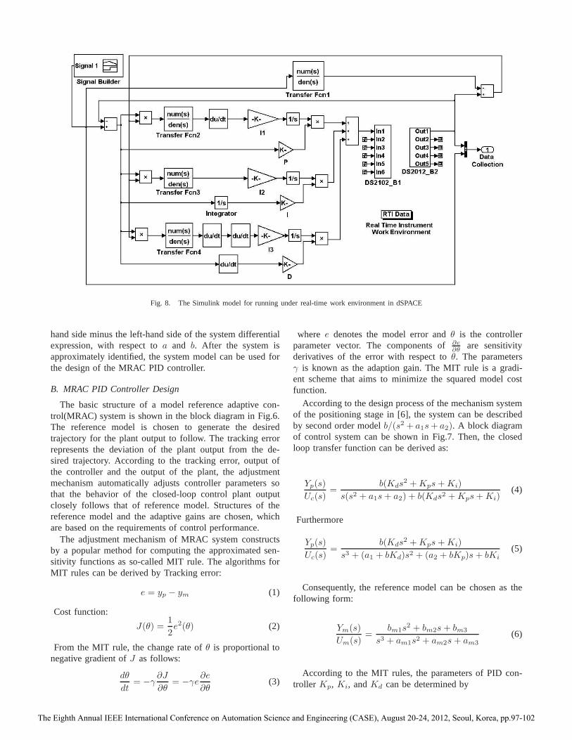
Fig. 8. The Simulink model for running under real-time work environment in dSPACE
hand side minus the left-hand side of the system differentialexpression, with respect toa and b. After the system isapproximately identified, the system model can be used forthe design of the MRAC PID controller.
B. MRAC PID Controller Design
The basic structure of a model reference adaptive con-trol(MRAC) system is shown in the block diagram in Fig.6.The reference model is chosen to generate the desiredtrajectory for the plant output to follow. The tracking errorrepresents the deviation of the plant output from the de-sired trajectory. According to the tracking error, output ofthe controller and the output of the plant, the adjustmentmechanism automatically adjusts controller parameters sothat the behavior of the closed-loop control plant outputclosely follows that of reference model. Structures of thereference model and the adaptive gains are chosen, whichare based on the requirements of control performance.
The adjustment mechanism of MRAC system constructsby a popular method for computing the approximated sen-sitivity functions as so-called MIT rule. The algorithms forMIT rules can be derived by Tracking error:
e = yp − ym (1)
Cost function:
J(θ) =1
2e2(θ) (2)
From the MIT rule, the change rate ofθ is proportional tonegative gradient ofJ as follows:
dθ
dt= −γ
∂J
∂θ= −γe
∂e
∂θ(3)
where e denotes the model error andθ is the controllerparameter vector. The components of∂e
∂θare sensitivity
derivatives of the error with respect toθ. The parametersγ is known as the adaption gain. The MIT rule is a gradi-ent scheme that aims to minimize the squared model costfunction.
According to the design process of the mechanism systemof the positioning stage in [6], the system can be describedby second order modelb/(s2 + a1s+ a2). A block diagramof control system can be shown in Fig.7. Then, the closedloop transfer function can be derived as:
Yp(s)
Uc(s)=
b(Kds2 +Kps+Ki)
s(s2 + a1s+ a2) + b(Kds2 +Kps+Ki)(4)
Furthermore
Yp(s)
Uc(s)=
b(Kds2 +Kps+Ki)
s3 + (a1 + bKd)s2 + (a2 + bKp)s+ bKi
(5)
Consequently, the reference model can be chosen as thefollowing form:
Ym(s)
Um(s)=
bm1s2 + bm2s+ bm3
s3 + am1s2 + am2s+ am3
(6)
According to the MIT rules, the parameters of PID con-troller Kp, Ki, andKd can be determined by
The Eighth Annual IEEE International Conference on Automation Science and Engineering (CASE), August 20-24, 2012, Seoul, Korea, pp.97-102

dKp
dt= −γp
∂J
∂Kp
= −γp(∂J
∂ε)(
∂ε
∂yp)(
∂yp∂Kp
)
dKi
dt= −γi
∂J
∂Ki
= −γi(∂J
∂ε)(
∂ε
∂yp)(
∂yp∂Ki
)
dKd
dt= −γd
∂J
∂Kd
= −γp(∂J
∂ε)(
∂ε
∂yp)(
∂yp∂Kd
)
(7)
where∂J/∂ε = ε, ∂ε/∂y = 1, ∇ = d/dt
∂yp∂Kp
=b∇
∇3 + (a1 + bKd)∇2 + (a2 + bKp)∇+ bKi
·[Uc − Up] (8)
∂yp∂Ki
=b
∇3 + (a1 + bKd)∇2 + (a2 + bKp)∇+ bKi
·[Uc − Up] (9)
∂yp∂Kd
=b∇2
∇3 + (a1 + bKd)∇2 + (a2 + bKp)∇+ bKi
·[Uc − Up] (10)
Then,∂Kp
∂t,∂Ki
∂t,∂Kd
∂tcan be derived by
dKp
dt= −γp
∂J
∂Kp
= γpεb∇
∇3 + (a1 + bKd)∇2 + (a2 + bKp)∇+ bKi
·[Uc − yp] (11)
dKi
dt= −γi
∂J
∂Kp
= γpεb
∇3 + (a1 + bKd)∇2 + (a2 + bKp)∇+ bKi
·[Uc − yp] (12)
dKd
dt= −γd
∂J
∂Kp
= γpεb∇2
∇3 + (a1 + bKd)∇2 + (a2 + bKp)∇+ bKi
·[Uc − yp] (13)
A block diagram is shown in Fig.8, the model reference-based adaptive PID controller in Simulink will be compiledand downloaded into dSPACE for real time running.
Fig. 9. Reference and response in x-direction when trackinga circle
Fig. 10. Reference and response in y-direction when tracking a circle
V. EXPERIMENTS AND DISCUSSIONS
After the approximated model of the system is identifiedand the MRAC PID controller is built up in the MAT-LAB Simulink real-time workshop(RTW) environment, theSimulink model can be complied and downloaded into thedSPACE to run in realtime with the hardware in loop. Thesoftware Control Desk is used to supervise the experimentalprocess and upload the experiment data instantaneouslythrough optical fiber communication tool set.
In the experiment, two sinusoidal waves in two directionsare used to drive the mobile stage to follow a circle, thelearning and self adaptive time can be seen clearly fromFig.9 to Fig.10. It needs about 50s for the controller to learnand adapt the plant well. After the adaptive time, it can beseen that the mobile stage can track the given reference pathexactly. It can be seen from Fig.11 and Fig.12, after 100s,the hysteresis problems are almost canceled, the responsecan track the reference signals well in both directions. Thewhole tracking performance can be seen in Fig.13. Afterthe learning and adaptive period, the response follows thereference path exactly.
Compared with the previous simple PID control method,the MRAC-PID controller can tune the PID parameters auto-matically and make the system stable in the whole workingrange. But such a long learning and adaptive time may limitthe application field of the designed positioning stage. Thislong time adaptive time may come from the approximated
The Eighth Annual IEEE International Conference on Automation Science and Engineering (CASE), August 20-24, 2012, Seoul, Korea, pp.97-102
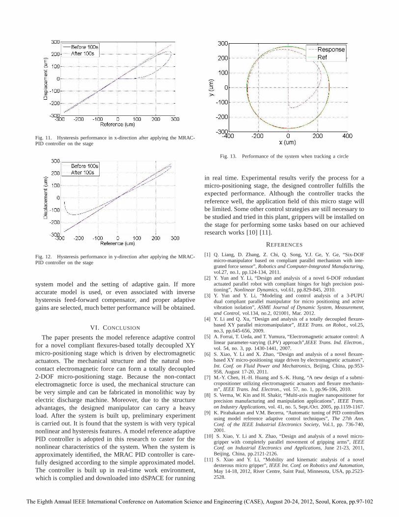
Fig. 11. Hysteresis performance in x-direction after applying the MRAC-PID controller on the stage
Fig. 12. Hysteresis performance in y-direction after applying the MRAC-PID controller on the stage
system model and the setting of adaptive gain. If moreaccurate model is used, or even associated with inversehysteresis feed-forward compensator, and proper adaptivegains are selected, much better performance will be obtained.
VI. CONCLUSION
The paper presents the model reference adaptive controlfor a novel compliant flexures-based totally decoupled XYmicro-positioning stage which is driven by electromagneticactuators. The mechanical structure and the natural non-contact electromagnetic force can form a totally decoupled2-DOF micro-positioning stage. Because the non-contactelectromagnetic force is used, the mechanical structure canbe very simple and can be fabricated in monolithic way byelectric discharge machine. Moreover, due to the structureadvantages, the designed manipulator can carry a heavyload. After the system is built up, preliminary experimentis carried out. It is found that the system is with very typicalnonlinear and hysteresis features. A model reference adaptivePID controller is adopted in this research to caster for thenonlinear characteristics of the system. When the system isapproximately identified, the MRAC PID controller is care-fully designed according to the simple approximated model.The controller is built up in real-time work environment,which is complied and downloaded into dSPACE for running
Fig. 13. Performance of the system when tracking a circle
in real time. Experimental results verify the process for amicro-positioning stage, the designed controller fulfillstheexpected performance. Although the controller tracks thereference well, the application field of this micro stage willbe limited. Some other control strategies are still necessary tobe studied and tried in this plant, grippers will be installed onthe stage for performing some tasks based on our achievedresearch works [10] [11].
REFERENCES
[1] Q. Liang, D. Zhang, Z. Chi, Q. Song, Y.J. Ge, Y. Ge, “Six-DOFmicro-manipulator based on compliant parallel mechanism with inte-grated force sensor”,Robotics and Computer-Integrated Manufacturing,vol.27, no.1, pp.124-134, 2011.
[2] Y. Yun and Y. Li, “Design and analysis of a novel 6-DOF redundantactuated parallel robot with compliant hinges for high precision posi-tioning”, Nonlinear Dynamics, vol.61, pp.829-845, 2010.
[3] Y. Yun and Y. Li, “Modeling and control analysis of a 3-PUPUdual compliant parallel manipulator for micro positioningand activevibration isolation”,ASME Journal of Dynamic System, Measurement,and Control, vol.134, no.2, 021001, Mar. 2012.
[4] Y. Li and Q. Xu, “Design and analysis of a totally decoupled flexure-based XY parallel micromanipulator”,IEEE Trans. on Robot., vol.25,no.3, pp.645-656, 2009.
[5] A. Forrai, T. Ueda, and T. Yumura, “Electromagnetic actuator control: Alinear parameter-varying (LPV) approach”,IEEE Trans. Ind. Electron.,vol. 54, no. 3, pp. 1430-1441, 2007.
[6] S. Xiao, Y. Li and X. Zhao, “Design and analysis of a novel flexure-based XY micro-positioning stage driven by electromagnetic actuators”,Int. Conf. on Fluid Power and Mechatronics, Beijing, China, pp.953-958, August 17-20, 2011.
[7] M.-Y. Chen, H.-H. Huang and S.-K. Hung, “A new design of a submi-cropositioner utilizing electromagnetic actuators and flexure mechanis-m”, IEEE Trans. Ind. Electron., vol. 57, no. 1, pp.96-106, 2010.
[8] S. Verma, W. Kin and H. Shakir, “Multi-axis maglev nanopositioner forprecision manufacturing and manipulation applications”,IEEE Trans.on Industry Applications, vol. 41, no. 5, Sept./Oct. 2005, pp.1159-1167.
[9] K. Pirabakaran and V.M. Becerra, “Automatic tuning of PID controllersusing model reference adaptive control techniques”,The 27th Ann.Conf. of the IEEE Industrial Electronics Society, Vol.1, pp. 736-740,2001.
[10] S. Xiao, Y. Li and X. Zhao, “Design and analysis of a novelmicro-gripper with completely parallel movement of gripping arms”, IEEEConf. on Industrial Electronics and Applications, June 21-23, 2011,Beijing, China, pp.2121-2126.
[11] S. Xiao and Y. Li, “Mobility and kinematic analysis of a noveldexterous micro gripper”,IEEE Int. Conf. on Robotics and Automation,May 14-18, 2012, River Centre, Saint Paul, Minnesota, USA, pp.2523-2528.
The Eighth Annual IEEE International Conference on Automation Science and Engineering (CASE), August 20-24, 2012, Seoul, Korea, pp.97-102


![MRAC Validation arXiv:2003.11292v1 [eess.SY] 25 Mar 2020](https://img.dokumen.tips/doc/110x75/61ed29642218615c3240b988/mrac-validation-arxiv200311292v1-eesssy-25-mar-2020.jpg)