Embed Size (px)
Citation preview

\'
I
A HICRO-PASCAL INTERPRETER
HASTEB OF SCIENCE ( 1977) (Computation)
I1cNASTER UNIVERSITY Hamilton, Ontario
TITLE: A Micro-Fascal Interpreter
AUTHOR: David R. Bandy, B.Sc. (McMaster)
SUPERVISOR: Dr. N. Solntseff
NUMBER OF PAGESa viii, 91
11

A f.li CRO-P AS CAL
INTERPRETER
by
DAVID R. BANDY, B.Sc.
A Project
Submitted to the School of Graduate Studies
in Partial Fulfilment of the Requirements
for the Degree
ltlaster of Science
McMaster University
September 1977
c
ABSTRACT
A discussion of portability is presented along
with a. description of the i1ICRO-F'ASCAL language. The
program developed and documented in this project,
accepts an intermediate abstract machine lan~lage (intcode)
as input and executes these 1ntcode programs on the HP2100.
A description of the intcode instruction set and the
microprograms used in the interpreter is given. The
Nicro-Pascal Ba.ch1ne design reflects the current trend to
increase program portability.
111

ACK1\IOWLEDG2NENTS
I want to thank my supervisor Dr. N. Solntseff,
Nark Green and Chris Bryce for their kind help during
my project. An honourable mention is reserved for the
secretaries of the Applied Hathematics Department whose
good spirit is always refreshing. The typing was ably
handled by Virginia Rakoczy.
lv

INDEX
CHAPTER 1 INTRODUCTION
1.1 Portability 1.1.1 How Can Portability Be Achieved
1.1.2 Problems
1.2 Interpreters and Compilers 1.) The Portable STAB System
CHAPTER 2 MICRO-PASCAL
Design Philosophy
Basic Features 2.1
2.2
2.3 2.4 2.5 2.6
Micro-Pascal Machine Portability and. MICRO-PASCAL Language Assessment Interpreter Outline
CHAPTER J INTERPRETER DESCRIPTION
).1 Structural Design
).2 The Micro-Pascal ~Achine
).2.1 Data Representations 3.2.2 Procedure Structure
I
).2.) Addressing Modes
).2.4 Instruction Set
J.J Code Discussion
j.).l Main Program
\._
v
Page
1
1
J 4
5 6
8
8
10
11·
12
lJ
15 . 1?.
18 19 20
21
JJ JJ

J;.J.2 3.3.3
Subroutine Design
Fro gram Input
J.4
3.4.1 3.4.2
3.4.3 3.4.4
Using The Interpreter
Frogra.m Input
Output
Summary of Error Messages
Input/Output B.outines
Instruction resting
CF~PTER 4 MICROCODING
4.1 I1icroprogra.mming On The HP2100
4,2 Microprograms For The Interpreter
4.2.1 INCST
4.2.2 DECST
4.2.3 GBYTE
CF..APTER 5 INTERPRETER TESTING
5.1 Ideal Interpreter Test Program
5.2 Sample Programs
Test Progra.m One
Test Program Two
CF..APTER 6 SUNFiARY
Conclusion
APPENDIX A Running The Interpreter
APFENDIX B
APPENDIX C
ARITH
Listing Of HP Microprograms
Test Frogra.ms
vi
Page
37 37
39
J9 40
40
41
42
44
45 45 47
47
50 53 54 61
67
69
72
75
81
81

BFUNC
LOAD+ STORE
LOGIC
MANIP
PC ALL
TRANS
Test of Error Messages
BIBLIOGRAPHY
REFERENCES
vii
Page
82
8)
84 86 8?
88
89
91
91

FIGUHES
2.1 Data Types
2. 2 EICRO-FASCAL InterpretB.tion on HF2100
3.1 Table of Subroutines
3.2 Subroutine Hap
3.3 Instruction Register
3.4 Stack Representation of String
3.5 Stack Representation of An Array Header
).6 Procedure Header Format
].7 Stack Set-Up for Load Using Relative Address
3.8 Stack Set-Up for Store Using Relative Address
).9 Relative to Absolute Address Conversion
J.lO Two-Byte Integer Load
).11 Two-Byte Integer Store
J.12 Two-Byte Integer Stack Configuration
).13 Case Header Format
3.14 Flowchart of Main Program
3.15 Input Stream Subgroups
3.16 Fix-Up Group Description
).17 Sta.ck Configuration for Procedure Test Program
4.1 Flowchart of INCST Microroutine
4.2 Flowchart of DECST M1croroutine
4.3 Flowchart of GBYTE M1crorout1ne
v111
35.
Fage
9
11
15 16
18 18
19 20
22
23 24
25 26
27
31
36
37
38
43 46
47
49

CF.APTER 1
INTRODUCTION
This project documents the development of an
interpreter to execute intermediate code representations
of I~ICRO-FASCAL programs on the Hewlett-PackArd 2100.
The interpreter is one part of a portable language system
known as the I'ficro-Pa.sce.l Hachine. This introductory
chapter considers the portability question in general and
documents my own experience with the portA.ble STAB system.
1.1 Portability
Portability is R subjective measure of ease
with 1Arhich ft program can be moved from one instella.tion
to another. A program is highly portable if the effort
required to transfer it is significantly less than the
original implementation effort. Adaptability is a. related
problem which measures the eAse of progrem alterRtions
needed to meet different system constraints. The
difference in these two operations is that portAbility
concerns environment~lly governed changes in the algorithm.
The need for portability seems to arise in two
situations. In the first case, programs should be portable
1

2
over a whole machine range to permit moving to a larger
machine or adding a smaller one in parallel. The second
case concerns portability to and from alien machines. An
installation with a program library that 1s highly portable
is not as apt to be committed to a specific computer or
manufacturer. SUch an installation has a better bargaining
position when in the market for new machinery. Manufacturers
whose programs are portable are able to provide working -
software in short order to complement new hardware.
A program package written 1n a portable fashion is
more attractive to other installations due to the relative
ease in adaptation. Programmers can often save time and
effort by adapting an existing program that does some or
all of the desired task instead of designing a new one
from scratch. As an illustration, academic and research
people could move to other installations easily and
exchange portab~ designed programs avoiding much wasteful
duplication.
It has been said that programs should not be
portable because they can be improved if they are rewritten.
However if a program is portable the user has the option
to allocate resources to improve it or rewrite the program.
Even if the decision is made to rewrite, the portable
version can be used during the rewrite period and as an
aid 1n designing the new program.

In summary the advantages of portability lie in
the minimization of development time and duplicate
programming effort, the reta.ined usefulness of older
programs and the increased mobility of program packages.
1.1.1 How Can Portability Be Achieved?
3
Portability requires a program to be independent
of special properties of the operating system or, more
generally, requires that an appropriate program environment
be provided on many current installations. Some people
have suggested rigid standardization as a possible
solution. This solution would permit greatly increased
application portability. However, program packages like
compilers and operating systems would still have to be
installation dependent. In the past, standards have been
incomplete, compromised because specific machine features
were not exploited and several years behind current trends.
Another solution may lie in machine independent
systems. Machine independence refers to program
properties that isolate it from the details of the computer
structure such as word length, addressing scheme and the
number and kind of registers.
These two solutions to the portability problem are
'different yet not mutually exclusive. Both properties can
be achieved by using a high-level programming language.
4
These programs are machine dependent only with respect
to the accuracy of real arithmetic, the range of arithmetic
values and the character set. The character set problem
can be partially alleviated through the use of a standard
48 character set. Programs written in high-level
langua.ges are more portable if the use of Input/Output is
restricted to the more standard sequential files.
Anoth~r solution suggests dividing a program into
a data description segment and an algorithmic section. The
algorithmic part would be as machine independent as
possible while the data description would be adjusted to
cope with the host machine. An abstract machine model is
a mechanistic interpretation of the data and algorithm
split up. The basic operations and data types are used to
define a fictitious computer or abstract machine. An
abstract machine model of this type can be used to construct
a new high-level language like HICRO-PASCAL and the
Hicro-Pascal Hachine.
1.1.2 Problems
One of the problems facing program portability is
the lack of good current programming standards. Strict
adherence to such standards will pave the way for more
portable programs. Portability is hindered by the wide
variation in machine codes and architectures currently
available in the market place.
5
Historically tasks such as input/output ~nd code
generation have relied on machine-code programming. These
habits must be broken if more porta.ble programs are to be
written.
It is often claimed that portable software is
synonymous with inefficient software. Unfortunately
this has frequently been the case. Inefficiency usually
stems from data packing schemes that are not suited to
fast access on the host computer, very complicated
interfaces to the environment like the operating system
and inefficient code for heavily repeated loops. The
trade-off between portability and efficiency is a problem
that will likely persist for some time. Its current
solution lies in minimizing the inefficiency until machine
architectures and therefore machine-codes become
standardized.
1.2 Compiler - Interpreters and Compilers
Consider the differences in compiler - interpreter
and compiler systems in the light of our portability
discussion. A compiler - interpreter, as the name suggests,
performs two functions, In the first phese,it Analyzes
the complete source program and translates it into an
internal form. The second phase interprets or executes
the internal code representation of the source program.

6
In compiler systems the source progr~m 13 analyzed
and translated into object code. Fro~r~ms compiled into
object code usual1y execute faster beceuse this code is
handled faster by system routines than internal code is by
the interpreter. Compiler - interpreter systems tend to be
more portable thRn compiler systems. The compilation phase
is largely machine independent and can usually be lifted
intact for a transfer. The execution segment is fairly
stra.ight-forwa.rd and can be NTi tten for the host machine
without undue difficulty if the documentation is thorough.
Compiler systems generate machine dependent object
code which makes them significHntly less portA-ble. However,
if the system was written to be reasonably portable and
modifiable the prospects for successful transfer are
dramatically improved. The mRchine dependent area.s such as
code generation and input/output could be clearly marked
so that modifications could proceed as smoothly as
possible.
1.3 The Portable STAB System
Prior to this project I spent about six weeks
working with the portable STAB system. The STAB machine
is very similar to the Hi cro-Fasce.l Nachine. STAB source
code is compiled into an intermediate machine language
which is subsequently interpreted.

S'rAB is a. progre,mming language spawned from BCf'L
and designed as a high-level language implenent~ble on
small machines as ~-1ell 9S Et straight-for~'lard compiler
i-Iri ting tool. I was writing a. new STAB compiler because
the existing one tva.s unstructured, unreadable and
unmodifiable. As parts of the new compiler were written
they were tested using the old compiler. This testing
procedure was hampered considere.bly by numerous errors
detected in my source code by the old compiler, ~~ny
7
of the errors were not sufficiently explained by the err6r
messages or by the STAB programming language documentation.
Numerous errors remained a mystery to both my supervisor,
Dr. Solntseff and myself. Initially I was able to correct
these errors by intuition and program re-organization.
However, as time went on the situation deteriorated to the
point where little real progress was being made on my
compiler and its code was so significantly altered to
facilitate a clean compile that it was inefficient, At this
point the project was halted and this project started.
The portable STAB system failed on two accounts: a
poor compiler a.nd insufficient documenta.tion. :·Je can
conclude that a portable system needs a readable, structured
and easily modifiable compiler eccompanied by a full and
thorough documentation to be workable in A new surrounding,

CHAPTER 2
NIGRO-PASCAL
2.1 Design Philosophy
NICRO-PASCAL is a high-level langua.ge to be
implemented on micro or mini-computers like the HP2100.
It is a lan~tage well suited for writing compilers in a
readable, understandable and modifiable form.
2.2 Basic Features
r•IICRO-FASCAL, as 1 ts name would suggest, is
modelled after the full PASCAL language. The quantities
in a Micro-Pascal program are constants, simple variables,
arrays, strings, procedures and the presently unimplemented
functions. There are five types of declarations: labels,
constants, variables, procedures and functions. Data
types fall into three categories based on their size.
8

9
SIZE NAHE DESCRIPTION
One Byte Byte integer
Char character
Two Byte Integer integer
N Byte String character string
Array integers, characters
figure 2.1 Data Types
Numbers in MICRO-PASCAL are represented by one or two byte
integers.
Arithmetic operations available include addition,
subtraction, multiplication and division on BYTE and
INTEGER types. The basic boolean operations of EQ, NE,
LT, LE, GT, GE, AND, OR and NOT exist for BYTEs and
INTEGERs. I1ICRO-PASCAL has four basic input/output
operations, READ-reads from the current input buffer,
READLN-terminates reading from the current input buffer,
WRITE-writes to the output buffer and WRITELN-dumps the
output buffer to the desired output unit.
Valid statements include a compound form as well
as the standard assignment. A compound statement consists
of a group of statements surrounded by a BEGIN and an END.
The Hicro-Pascal control statements are limited to a GOTO.

an IF-THEN and IF-THEN-ELSE block, a CASE block and a
~fHILE-DO repea. t block. Parameter passing on procedure
calls is limited to call by value only.
Some of the PASCAL features removed from
HICRO-FASCAL include sets, records, pointers, types,
10
reals and the REPEAT and FOR statements. Fuller
documentation on HICRO-PASCAL is available elsewhere.(GRE)
2. 3 Micro-Pascal T1R.chine
We refer to the Micro-Pascal package as the
Micro-Pascal Machine. The Micro-Pascal source program
is executed by a compiler - interpreter which works in
two phases. Source code is first compiled into an
intermediate abstract machine language referred to as
intcode. The intcode is then executed on the host machine.
i>ly goal, in this project, is to develop and document an
interpreter to execute intcode programs on the Hewlett
Packard 2100.

Ftrst Fh~se
I·~ICE.O- :t; AS C1.\L ~
.SCUnCZ
~econd Fh9,se
INTCODE )
I-:icro-I'Pscal Compiler --7 INTCODE
~rlri tten in r:I-F
ProgrAm written in RP
A.ssembly lang-119 ge Rnd
microcode executes
intcode instructions.
11
figure 2. 2 I'Iicro-Fa.scfll Interpretation on HF2100
The Eicro-Fascal Machine hes alreRdy been
implemented on the CDC 6400. This project will ~llow
Micro-Fascal progrems to be compiled into intcode on the
CDC then executed on the HF2100. The full Micro-rascal
I~achine will be realized on the HF2100 11-rhen the compiler
is written in MICRO-FASCAL end interpreted into lntcode.
2.4 Fortability and NICRO-FASCAL
~e can now consider the Vicro-Fascal Machine with
respect to the portability queRtion. The compile phase of
interpretation is fairly machine independent since it is
written in NIGRO-PASCAL and generates the stf\nde,rd
abstract machine language as code. It could be used with
intcode executors on vRrious host machines requiring only
minor alter~tions if ~ny.

The execution phase of the interpreter is firmly
rooted in the host machine. Its flexibility stems from
the fact that a compile operation for Rny source len~tage
emitting compAtible intcode programs could be used with
1 t. The execution phase could theoretics.lly be part of a
number of different lA-nguage me. chines or interpreters.
2.5 L8n~age Assessment
12
Even though MICRO-PASCAL and its implementations
are still in the experimentel ph~se, some general language
criticisms are worth considering. A Micro-Pascal program
must be compiled then interpreted. in order to run. This
two phase operation contributes to a lengthy totPl run
time as ~ell as a slow execution speed. Programmers
accustomed to the larger and more powerful high-level
languages such e,s PASCAL will find J'vliCRO-PASCAL restrict! ve,
at least initially, due to the limited control statements.
The size restriction on Micro-Pascal programs will depend
on the aveilable host machine memory and the efficiency of
the interpreter implementation.
A strong argument for MICRO-PASCAL is the
availability of a high-level language on a mini or micro
machine that has been previously restricted to lower-level
languages. The mini or micro-machine programmer is given
new freedom not present in Assembler and machine la.nguages.
This freedom should contribute to a reduction in program

13
development time. Since MICRO-PASCAL is a small and simple
language its compiler can be written using time and space
to maximum efficiency. In a small machine environment it
is essential that resources be efficiently allocated.
The Micro-Pascal system is semi-portable since the
compile phase emits a standard machine independent intcode.
Once the execution phase has been adapted to the host
machine to accept intcode,the standard compile program can
be used. MICRO-PASCAL is intended RS a modifiable system
which is fairly flexible to locRl tampering unlike some
systems such as PASCAL-S.
2.6 Interpreter Outline
The interpreter is written in Hewlett-Packard
assembly language E:tnd microcode. It accepts end executes
intcode programs which are read as a string of bytes.
These programs can be read by the interpreter from eny
specified input device. As currently implemented, input
during program execution is limited to cards and the
keyboard while output can be routed to the line printer or
the keyboard.
Instructions executed by the interpreter are at
least one eight-bit byte long and this first byte is split
into a group and level number. The main program decodes
the group and level components of the current instruction

and bra,nches to the required group subroutine. The flow of
control within the subroutine is based on the level number
and when it is matched the required instruction is executed.
Control is then returned to the main program where the
instruction cycle is repeated until the stop command is
encountered.

CHAPTER 3
INTERPRETER DESCRIPTION
).1 Structural Design
The interpreter consists of one main routine,
three m1crorout1nes, twenty-five subroutines and six
input/output subroutines. The heart of the interpreter is
the main program, INTRP, along with the subroutines ARITH,
BFUNC, LOAD, LOGIC, MANIP, PCALL, STORE and TRANS.
Assembler Subroutines
A - ARITH
B - ASSBY
c - BEGIN
D - BFUNC
E - DECSK
F - DIGIT
G - FINI
H - GETAD
I - GETBT
J - GETBY
K - GETIN
L - GPERR
I1 - GT2IN
N - INCSK
figure 3.1
N - INCSK
0 - LLERR
p -LOAD
Q - LOGIC
R - MANIP
s - PCALL
T - PUTBT
u - READP
v - STBYT
w - STINT
X - STORE
y - TRANS
z - ZASSY
Table of Subroutines 15
Microprogram
Subroutines
Ml - INCST
M2 - DECST
I-13 - GBYTE
I/O Subroutines
Il - WRCRT
12 - WRLP
IJ - RDCRD
I4 - RDCRT
I5 - RDPT
I6 - RDDSC
16
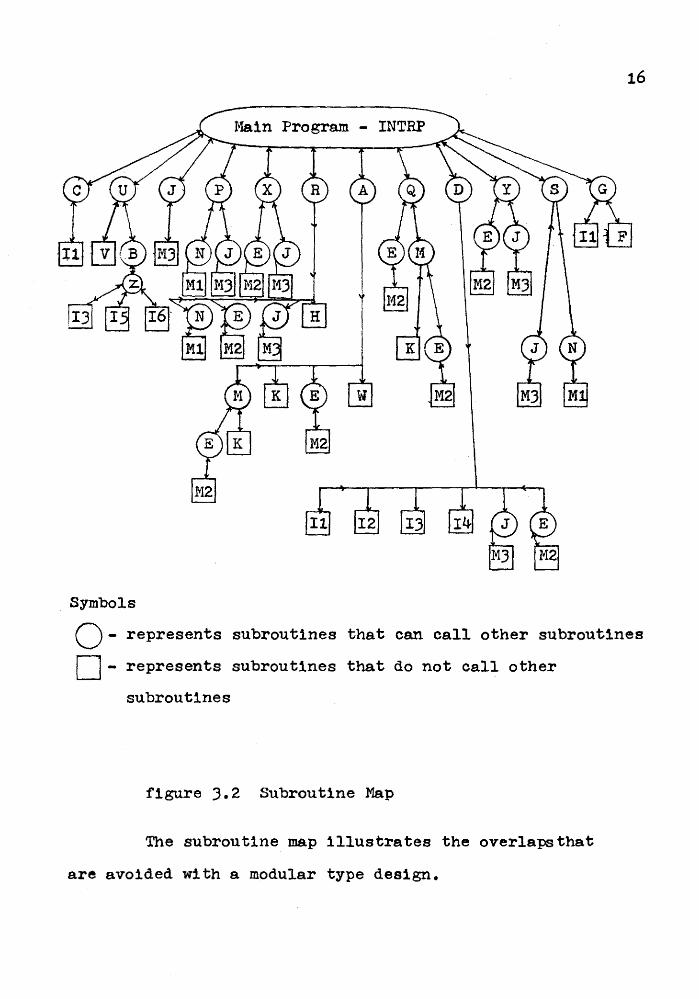
. Symbols
~-represents subroutines that can call other subroutines
c=J- represents subroutines that do not call other
subroutines
figure 3.2 Subroutine Map
The subroutine map illustrates the overlapsthat
are avoided with a modular type design.

).2 The Micro-Pascal ~Achine
The }Ucro-Pascal }~chine consists of three main
arrays: CODE, STACK and DSPLY and a few main pointers.
Intcode generated by the Micro-Pascal compiler is stored
17
two bytes per word in the CODE array. The instruction
pointer, IP, points to the executable byte in the CODE array.
The STACK array is used for run-time data storage and is
referenced by all but a few instructions. SP is the stack
pointer which indexes the top stack element. A zero SP
value indexes the first stack element. Even though each
stack element is two bytes large,only the lower byte is
used in the stack operations. The level of procedure
nesting is stored in LVL. DSPLY is a sixteen bit array
used in addressing and LVL is the index of the most
current entry. When a procedure is called,DSPLY(LVL + 1)
is set to the current value of SP. After procedure
execution the stack pointer can be reset to the proper
value using the DSPLY array. Initial values for these
variables are SP = O, LVL = O, DSPLY(LVL) = 0 and IP = 1.
All the interpreter instructions have an initial
byte of the following forms
18
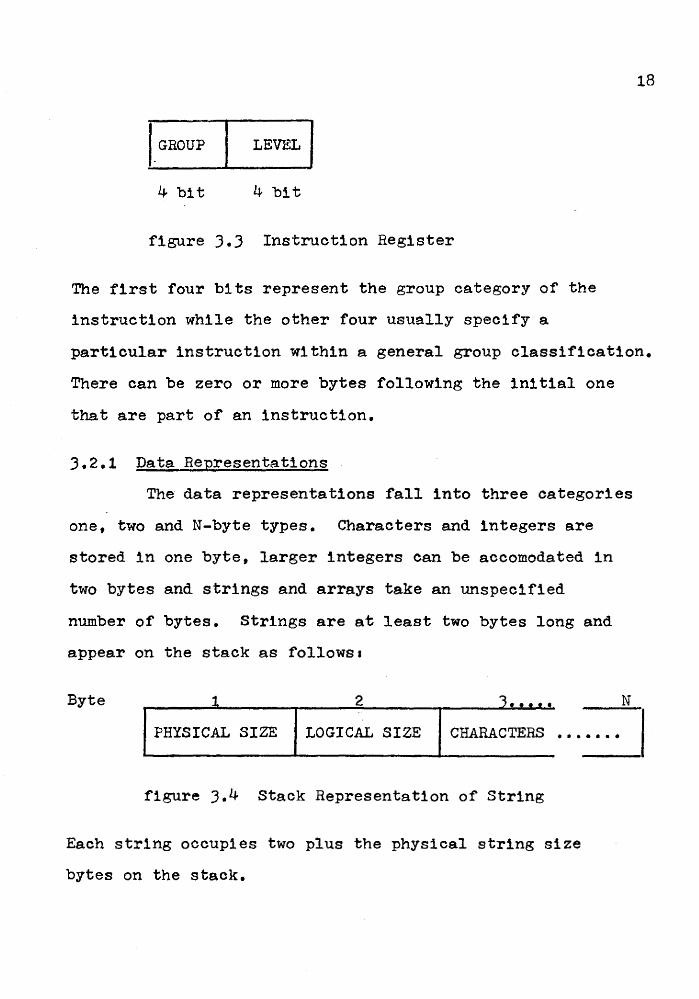
,_GROUP LEVEL
4 bit 4 bit
figure J.J Instruction Register
The first four bits represent the group category of the
instruction while the other four usually specify a
particular instruction within a general group classification.
There can be zero or more bytes following the initial one
that are part of an instruction.
3.2.1 Data Representations
The data representations fall into three categories
one, two and N-byte types. Characters and integers are
stored in one byte, larger integers can be accomodated in
two bytes and strings and arrays take an unspecified
number of bytes. Strings are at least two bytes long and
appear on the stack as follows•
Byte 1 2 '3 •••••
PHYSICAL SIZE LOGICAL SIZE CHARACTERS •••••••
figure ).4 Stack Representation of String
Each string occupies two plus the physical string size
bytes on the stack.
N

19
An array has a header that describes its structure
and data. The header appears on the stack as illustrated
below:
Byte 1 2 4 5 6
elsize dim # I 1;1 I size 1 lb2 size 2 •••
elsize - the total array size in bytes
dim # - the number of array dimensions
lbl - lower bound of the first array index
size 1 - the range of the first array subscript
upper bound - lower bound + 1 • • •
etc.
figure 3.5 Stack Representation of An Array Header
3.2.2 Procedure Structure
When a procedure is called,a seven-byte header is
created on top of the stack and an entry is made in the
DSPLY array which points to the start of the header. The
procedure call specifies the new value of LVL for the life
of the procedure and the address of the procedure.
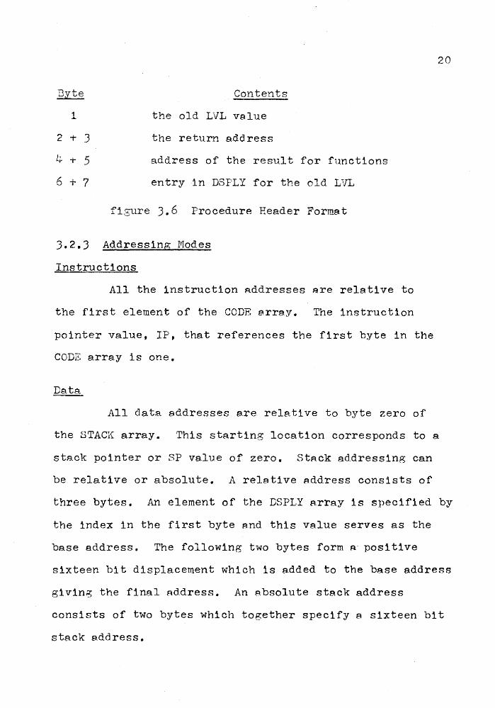
Byte
1
2 + 3
4 + 5
6 + 7
Contents
the old LVL value
the return e.ddress
address of the result for functions
entry in DSPLY for the old LVL
fisure 3. 6 Procedure Header FormB.t
3.2.3 Addressing Modes
Instructions
All the instruction addresses are relative to
the first element of the CODE errey. The instruction
pointer value, IP, that references the first byte in the
CODE array is one.
Data
All data addresses are relative to byte zero of
20
the STACK array. This starting location corresponds to a
stack pointer or SP value of zero. StAck addressing can
be relative or absolute. A relative address consists of
three bytes. An element of the DSPLY A.rray is specified by
the index in the first byte and this value serves as the
base address. The following two bytes form a· positive
sixteen bit displacement which is added to the base address
giving the final Rddress. An absolute stack address
consists of two bytes which together specify a sixteen bit
stack e.dd ress.
3.2.4 Instruction Set
The instructions currently implemented in the
interpreter are described belows
GROUP 0 - LOAD
This is a three-byte instruction in which the
LEVEL component of the first byte pointa to an entry in
the DSPLY array and this value acts as the base address.
The second and third bytes of the instruction form a
sixteen bit address, ADR. The byte at address
DSPLY(LEVEL) + ADR is loaded onto the top of the stack.
GROUP 1 - STORE
STORE is a three-byte instruction where the LEVEL
part of byte one specifies an element of the DSPLY array.
Bytes two and three form a sixteen bit address, ADR. The
byte on the top of the stack is stored at stack address
DSPLY(LEVEL) + ADR.
GROUP 2 - STACK MANIPULATION
Level
0 - In this two-byte instruction byte two specifies
the number of bytes by which the stack pointer is
to be incremented.
1 - The second byte is stored on top of the stack.
2 - The string following the first byte is stored onto
the stack. See figure ).4 for string format.
21

GROUP 2 - STACK HANIPULATION cont'd
Level
3 - The second byte speci~ies the number of following
bytes that are to be loaded onto the stack.
4 - The top three bytes on the stack specify an index
into the DSPLY array and a sixteen bit address,
ADR. The byte at DSFLY(LVL) + ADR is loaded onto
the stack
Low byte
of' address
High byte of address
LVL
figure 3.7
SF
SF - 1
SP - 2
Stack Set-Up for Load Using Relative
Stack Address
22
GROUP 2 - STACK NANIPULATION cont'd
Level
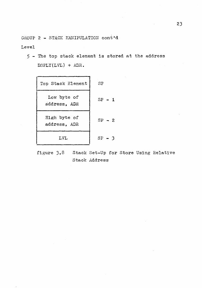
5 - The top stack element is stored at the address
DSPLY(LVL) + ADR.
Top Stack Element SF
Low byte of SP - 1
address, ADR
High byte of SP - 2
address, ADR
LVL SF - 3
figure 3.8 Stack Set-Up for Store Using Relative
Stack Address
23

GROUP 2 - STACK NANIFULATION cont'd
Level
6 - ri'he three-byte relat1 ve sta.ck address on the top of
the stack is converted to a two-byte absolute stack
address preceded by a zero byte.
Low byte of relative SP Low byte of absolute
address address
High byte of relative SP - 1
High byte of absolute address a_d.dress
LVL SP - 2 0
Stack Before Stack After
figure 3.9 Relative to Absolute Stack Address
Conversion
7 - The second byte specifies the number of bytes by
which the stack pointer is to be decremented,
24

25
GROUP 2 - STACK I1ANIPULATION cont'd
Level
8 - This instruction determines a relative stack address
SP
SP - 1
SP - 2
and loads a two-byte integer onto the stack using
that address. The top three stack elements form
the relative stack address, ADR. The high byte of
an integer stored at ADR is loaded onto the stack
at SP - 2 while the low byte of the integer is
loaded from ADR + 1 onto the stack at SP - 1.
Low byte ADR SP
High byte ADR SP - 1 Low byte of
Integer
LVL SP - 2 High byte of
Integer
• • • • • •
ADR + 1 Low byte of
Integer
ADR High byte of Integer
Stack Before
figure 3.10 Two-byte Integer Load
Stack After

26
GROUP 2 - STACK I1ANIPULATION cont'd
Level
9 - This instruction stores the two-byte integer on
top of the stack at the relative stack address,
SP
SP - 1
SP - 2
SP - J
SP - 4
ADR, specified by the three bytes below it.
Low byte of Integer
High byte of
~ Low byte of Integer
DSPLY(LVL) + ADB + 1
Integer ~ High byte of DSPLY(LVL)
Integer + ADR Low byte ADH
High byte ADR
LVL
Stack Before Stack After
figure J.ll Two-byte Integer Store
27
GROUP 3 - ABITm1ETIC OPERATIONS
Level
0 - The top stack element is negated in two's complement
form.
1 - The two bytes on top of the stack are added together
and stored at stack position SP - 1.
2- The byte at STACK(SP), the top stack element, is
subtracted from STACK(SP - 1) and the result is
stored at stack position SP - 1.
3 - The byte at stack position SP is multiplied by the
byte at SP - 1 and the result is stored at SP - 1.
4 - The byte at stack position SP - 1 is integer divided
by the byte at SP with the result stored at SP - 1.
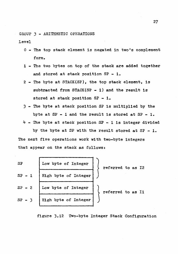
The next five operations work with two-byte integers
that appear on the stack as follows:
SP Low byte of Integer } referred to as I2
SP - 1 High byte of Integer
SP - 2 Low byte of Integer 1 referred to as Il
SP - 3 High byte of Integer
figure ).12 Two-byte Integer Stack Configuration

GROUP J - ARITI-Il·:E~rrc OPERATIONS con t 'd
Level
5 - The top two-byte integer, I2, is negated in t~o's
complei!lent form.
6 - Add the integers I2 and Il storing the low byte of
the integer result at SP - 2 and the high byte at
SP - 3.
7 - Subtract I2 from Il and store the result at SP - 2
and SP - 3.
8 - ~~ltiply I2 by Il and store the result at SF - 2
and SP - 3.
28
9 - Divide the integer Il by the integer 12 storing the
result at SP - 2 and SF - 3.
GROUP 4 - LOGICAL OF~::l:iATIONS
The top two stack elements are compared according
to the specified logical relation. If the relation holds
a one is placed at stack location SP - 1. Otherwise a
zero is placed at SP - 1. The logical operation is
performed as illustrated below.
STACK(SP - 1) Logical Operator STACK( SF)
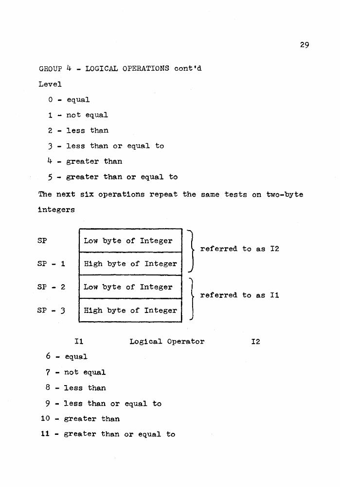
GROUP 4 - LOGICAL OPERATIONS cont'd
Level
0 - equal
1 - not equal
2 - less than
3 - less than or equal to
4 - greater than
5 - greater than or equal to
29
The next six operations repeat the same tests on two-byte
integers
SP Low byte of Integer referred to as I2
SP - 1 High byte of Integer
SP - 2 Low byte of Integer referred to as Il
SP - 3 High byte of Integer
Il Logical Operator I2
6 - equal
7 - not equal
8 - less than
9 - less than or equal to
10 - greater than
11 - greater than or equal to
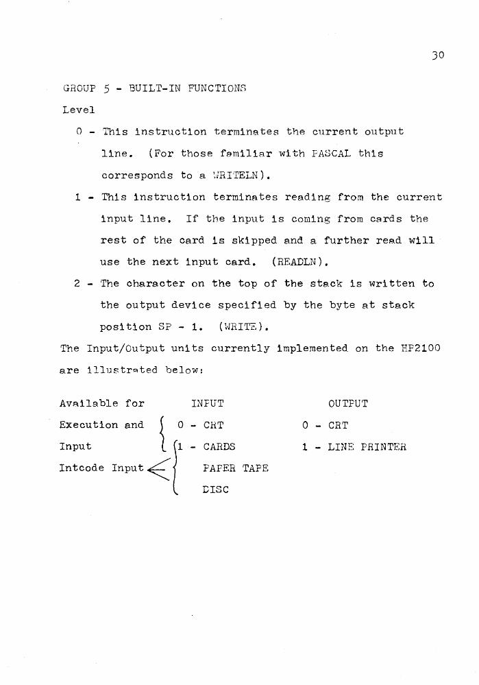
GROUP 5 - BUILT-IN FUNCTIONS
Level
0 - This instruction termine.tes the current output
line. (For those femiliar with PASCAL this
corresponds to a r.JRITELN).
JO
1 - This instruction terminates reading from the current
input line. If the input is coming from cards the
rest of the card is skipped and a further read will
use the next input card. (READLN).
2 - The character on the top of the stack is written to
the output device specified by the byte at stack
position SP- 1. (HRITZ).
The Input/Output units currently implemented on the HF2100
are illustr~ted below:
Available for
Execution and
Input
Intcode
INFUT
CRT
PAPER TAPE
DISC
OUTPUT
0 - CRT
1 - LINE PRINTER

GROUP 6 - TRANSFER OPERATIONS
Level
0 - This is an unconditional jump instruction. The
second and third bytes specify a relative
instruction address which is transferred to
immediately.
1 - This is a conditional jump instruction. The
second and third bytes provide a relative
instruction address which is transferred to if
the top stack element is zero. If the top stack
element is non-zero then the next instruction is
executed.
31
2 - This instruction specifies a case statement on the
top stack element. The GROUP - LEVEL byte is
followed by a number of case elements which consist
of a case header and code for the case element. The
case header format is
Byte 1 2 + 3
item address
figure 3.13 Case Header Format
where: item - the case label for the case element
address - the relative instruction address
of the next case header

GROUP 6 - TRANSFER OPERATIONS cont'd
Level
)2
2 - If the address value 1s zero then the case statement
has ended. Therefore the final case element
consists of an undefined item value and a zero
address. When the case statement is executed,
the ease header items are searched and compared with
the top stack item. If .a match 1:s made, the code
corresponding to the particular cas~ item is
executed before continuing with the next instruction
after·the case. When no match is made with top
stack element control passes directly to the
instruction after the case.
3- This 1nstruction·1s a procedure return which uses
the procedure header, created on call, to recreate
stack condition as they were before the call.·
These activities include resetting LVL, DSPLY(LVL),
the stack pointer, SP, and the instruction pointer,
IP, to the return address.
4 - This is the stop instruction which terminates
program execution.
GROUP 9 - PROCEDURE CALL
The two bytes after the GROUP - LEVEL byte specify
the relative instruction address of a procedure to be
called. A procedure header is created on top of the stack
JJ
as described in section 3. The base of the procedure
header is pointed to by the DSPLY(LEVEL) entry and control
is transferred to the procedure.
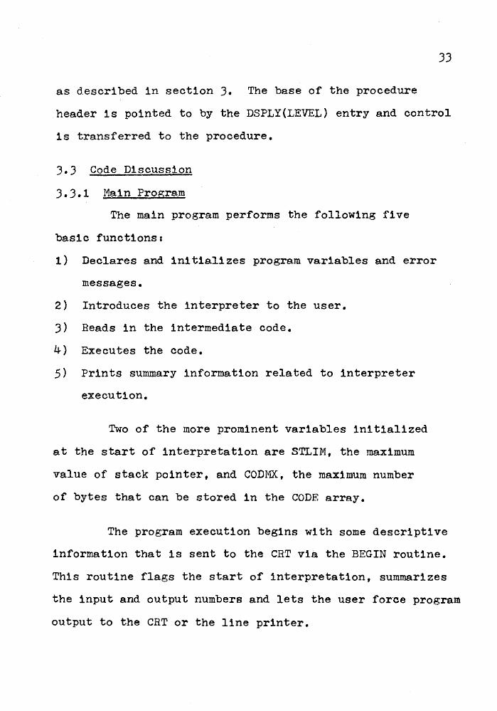
3.3 Code Discussion
3. 3.1 I1a1n Program
The main program performs the following five
basic funct1onsa
1) Declares and initializes program variables and error
messages.
2) Introduces the interpreter to the user.
J) Beads in the intermediate code.
4) Executes the code.
5) Prints summary information related to interpreter
execution.
Two of the more prominent variables initialized
at the start of interpretation are STLIM, the maximum
value of stack pointer, and CODMX, the maximum number
of bytes that can be stored in the CODE array.
The program execution begins with some descriptive
information that is sent to the CRT via the BEGIN routine.
This routine flags the start of interpretation, summarizes
the input and output numbers and lets the user for·ce program
output to the CRT or the line printer.

34
The intcode program is read into the CODE array
by the READP routine. A program pause occurs so the user
can specify the input device number. When this is
completed the program reads characters one at a time from
the input stream assembling instruction bytes and storing
them in the CODE array. Once the termination header is
encountered the reading process is over.
The transfer of control in the main execution
loop is based entirely on the group number of the current
instruction. The loop begins with a call to GETBY which
recovers the current instruction byte pointed to by IP.
This byte is split into the GROUP and LEVEL components
and the GROUP number tested against the valid possibilities.
(An error message for an invalid group number is emitted
if the matching attempt is unsuccessful.) If a match is
made,then the appropriate group subroutine is called to
execute the instruction. After exeeution,control returns
to the start of the loop where an end flag is inspected.
A--stop instruction sets this flag and brings the main
loop to an end.

INITIALIZE VARIABLES
INTRODUCTION TO INTERPRETER
READ IN THE PROGRAM IN INTCODE
ASSEMBLE THE NEXT
INSTRUCTION INTO ITS GROUP AND LEVEL PARTS
END MAIN LOOP PRINT OUT SUMMARY STATISTICS
35
figure 3.14. Flowchart
of Haln ProR;ram

YES
YES
YES
YES
YES
ERROR MESSAGE ILLEGAL GROUP NUMBER
figure 3.14 Flowchart of Main Program
37
3.3.2 Subroutine Desi~n
The Plein subroutines, ARITH, BFUNC, LCGIC, NANIP
and TRANS were written in as structured e.nd readable a
manner as possible in assembly language. The transfer of
control within these subroutines is based upon the LEVEL
number of the current instruction. A valid LEVEL value
uniquely defines en instruction within a GROUP subroutine.
These subroutines are equipped with error exits which
flag the occurrence of unexpected high LEVEL values after
the legal ones have been checked.
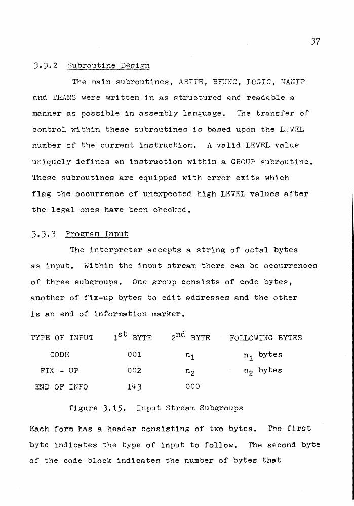
3.3.3 Program Input
The interpreter accepts a string of octal bytes
as input. Within the input stream there cs,n be occurrences
of three subgroups. One group consists of code bytes,
another of fix-up bytes to edit addresses and the other
is an end of information marker.
TYPE OF INFUT 1st BYTE 2nd BYTE FOLLOWING BYTES
CODE 001 nl n1 bytes
FIX - UP 002 n2 n2 bytes
END OF INFO 143 000
figure ).15. Input Stream Subgroups
Each form has a header consisting of two bytes. The first
byte indicates the type of input to follow. The second byte
of the code block indicates the number of bytes that

38
follow and are to be placed in the CODE array. A code
block must be the first form appearing in the input. It
can reappear anywhere in the input stream except as the
last block which is always the end of information. The
fix-up block can appear after eny code block. The number
of bytes in the block, specified by the second byte, is a
multiple of four since each fix-up instruction uses four
bytes. The I11cro-Pascal compiler uses a. one-pass approach
so that labels are often left unspecified until they are
encountered later on in the program scan. A zero address
is generated by the compiler when a label with an unknown
address is scanned. When the label is determined a fix-up
entry is prepared to replace the zero address.
Byte Number 1 2
form 16-bit
relative instruction
address - ADR
Fix-Up Address
High byte Low byte
J
load a.t
ADR
4
load at
ADR + 1
figure 3.16 Fix-Up Group Description
The first two bytes of the fix-up group specify a
sixteen bit relative instruction address within the CODE
array where the third byte will be loaded followed by the
fourth byte in the next location. Together,these final two

bytes form the previously undefined label address. The
end of information block occurs only once at the end of
the input stream.
3.4 Using The Interpreter
3.4.1 Program Input.
The intcode program can be read from disc, cards
39
and paper tape. Input is expected to be in the form of
octal bytes separated by some delimiter. Illegal
characters, those that are not octal digits, are completely
ignored. A sample program is illustrated below.
U?l
c·=·t 0 _,.1
..• ·!
·- L!C
:jCJO
1210 ;~i 044 r•o 1
1") - .:::
'1: •)
... ':1
l ·::!- 0 OCC! 0:1.? 0·":-l CJ.:::-1 1.:10 !~i :!. ;~:
000
CI41. ~::1nn
f::)Jji)
Ci'j 1 rj.:·! 0
(I 1 ~:: l 0 :l 0·:!-1
(1::)2
001
• --·f •• ••• J
;, ·!· 1 ~~j l,·.t
0~] _l
ij.::j. :1.
!~:; "'!· 0 c::::: l UUC!
!1 .. 0 0 l ~3
: C) 1 0 .:;. C -:100 014 -'!C iJ C·=:! ~:~
-· ?~::: 1 4 ·-~· Cl ,. : t:i 0 Ci 0 :,~i •1 <~i 0 0 :!. Cl -:-~ 0 f2: C 1 :') .::\. !J r) 0 1. {J •l 0 0 0 l o ~:. t :jO 1 •<21. ono o ·'- o oo 1 l:::ii~.IO H 1 ~~=~ .· 'l :l o :l ;~~
002 eoo O:JO
054 l ::::o U'=iO
~~tOO
,_., r=11
~~~~ 00
l 4:2 1 :::) .. ::' .-·~ ·-: t::~ .. ~-
!-:~ ·- '7 •:..• :.~ I
::::1!]0 040 000 C:IO 1
1·:·~ 0 oo::: _I ... I
000 0017.1 l,:)Ci 1 :~11:3 :l
147 ?ll ~:.?6
0 :~~
C! o:a o t-:::o •;_.100 ;:::34
CtOel ·~·12 (;:0:2 005

40
J.4.2 Output
Program output is normally routed to the unit
specified in the program code. It can also be directed to
the CRT or line printer by the user from the CRT.
3.4.3 Summary of Error Messages
After each error message printout we get the
normal program termination output which includes the
number of instructions executed, the maximum stack
pointer value during program execution and the program
size in bytes. The error messages are summarized below.
1) Group number of current instruction is not valid.
2) Level number of current instruction is too large.
3) CODE array is too small to accomodate the program.
4) The index of the DSPLY a.rray is greater than fifteen
and therefore references an out of bounds element.
5) The stack is too small for the current program, stack
overflow.
6) The stack pointer has been decremented below zero,
stack underflow.
7) An input block with an illegal type header, not 1, 2,
or 143, has been encountered.
If error three is encountered the size of the CODE
array can be increased by changing source lines 84 and
219. Similarly an occurrence of error five mey require

an increased stack size which can be ma.de by changing
source lines 91 and 213 • The dimension of the DSPLY
array limits the level of procedure nesting to fifteen.
3.4.4 Input/Output Routines
41
The input/output routines used by the interpreter
provide the interface between the Hewlett-Packard DOS-M
operating system and the Hicro-Pascal 1•1achine. This
group of routines makes available all of the peripheral
devices related to the Hewlett-Packard 2100 at Mcf1aster.
The routines are summarized below2
1) Line - Printer
2)
J)
4)
5)
6)
7)
8)
9)
Paper - Tape Punch
Paper - Tape Reader
CRT - Input
CRT - Output
Card - Reader
Read from Disc
Write to Disc
Write to Job Binary Area
All of these routines are
equipped to handle single
character and buffered
information.
These routines work
with one binary
byte.
10) ~lri te a record to Job Binary Area
11) Display time of day
These routines were written originally for use ln
the STAB system by my supervisor, Dr. N. Solntseff. The
routines currently used by the interpreter are 1, J, 4, 5,
6 and 7.

42
3.5 Instruction Testing
Programs were written to verify each group of
instructions. The test program created the conditions
where the operation of each instruction could be
sequentially checked. This checking procedure was possible
using a debug package loaded with the program. Stack
conditions including the stack pointer were sampled before
and after the instruction execution. The actual stack
configurations were checked against the expected values
which were calculated by hand before execution. All of the
test programs are included in Appendix c. The testing
process is illustrated here for the procedure call and
return program.

Ire-Calculated Results
E>F
1) Load 1 onto the stack, .SP ..... 1 4
2) Load 2 onto the stack, sp~ 2 0
J) Procedure call - return address 12,
SP,.....11
0
0
12
11
10
7
6 4) Load 4 onto the stack, sp.,_ 12
5) Procedure return,
Set If .,.__12
LVL 4-0
SF._ 2
6) Load 377 onto the stack, SP--3
7) Stop
Octal Representation of Program
041
012
143
001
041
041
377
002
144
220
041
0
7
Q_
0
2
1
figure 3.17
I 377
Stack
5
4
3
2
1
0
ConfigurAtion for
Procedure Test Program
000
004

CHAPTER 4
1-liCROCODING
4.1 Microprogramming On The HP2100
The Hewlett-Packard 2100 used in this project is
equipped with microprogramming facilities. It has four
writable control store modules where the micro-instructions
are stored. Module 0 contains the basic 2100 instruction
set, module 1 the floating point instructions and the
remaining modules 2 and 3 are available for programmer
use. A microprogram is a program-structured s~quence of
commands residing in the hardware or writable control store.
When a microprogram is executed it is translated into
hardware actions by hardware controls. This hardware
translation means fast and efficient execution.
Microprograms are usually more difficult to write because
they work on such a primitive level. Further information
on Hewlett-Packard Microprogramming can be found in the
HP2100 Microprogramming Guide and Microprogramming Software
Handbook.
The three most frequently called subroutines:
DECSK-stack decrementat1on, INCSK-stack 1ncrementat1on and
GETBY-extract1on of next instruction byte were chosen for
44
microcoding because they would maximize the increase in
interpreter execution speed and could be implemented
fairly quickly.
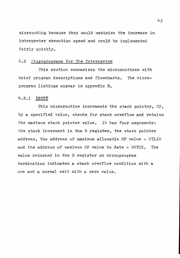
4.2 ~ioroprograms For The Interpreter
This section summarizes the microroutines with
brief program descriptions and flowcharts. The micro
program listings appear in Appendix E.
4.2.1 INCST
45
This microroutine increments the stack pointer, SP,
by a specified value, checks for stack overflow and retains
the maximum stack pointer value. It has four arguments:
the stack increment in the B register, the stack pointer
address, the address of maximum a.llol~able SP value - STLIH
and the address of maximum SP value to date - MSTCK. The
value returned in the B register on microprogram
termination indicates a stack overflow condition with a
one and a normal exit with a zero value.

FLAG
OVERFLOW
CONDITION
figure 4.1 INCST
46
SP +- SP + INCREMENT
'fes
No
YES
MSTCK +--- SF

4.2.2 DECST
This routine decrements the stack pointer, SP,
by a specified value and checks for stack underflow. It
has two arguments, the stack pointer address and the
47
stack pointer decrement in the B register. On microprogram
exit an A register value of one indicates stack underflow
while a zero value flags a normal termination.
FLAG STACK
UNDERFLOW
figure 4.2 DECST
YES
SP .,__ SF - DECREMENT
NO
48
4.2.3 GBYTE
This routine extracts a specified byte out of an
array of two byte words. It has two arguments, the
starting address of the array and the index of the desired
byte in the B register. The index specifies a particular
byte within an array word. This array word is determined
from the index value and the byte is extracted from it.
The byte is returned in the A register.
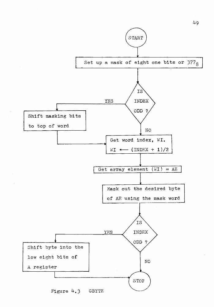
Shift masking bits
to top of word
Shift byte into the
low eight bits of
A register
Figure 4.3
Set up a mask of eight one bits or 3778
YES
Get word index, WI.
Ttl I +- ( INDEX + 1 ) /2
Get array element (WI) = AE
Mask out the desired byte
of AE using the mask word
YES
CF...APTER 5
INTERPRETER TESTING
The interpreter testing process is intended to
verify the instruction set and monitor its performance
on complete programs. Two I•'licro-Pa.sce.l test programs
included in this chapter illustrate the latter quality.
The interpreter instruction set was verified using the
test programs documented in Appendix c. In the following
section a more comprehensive possible test program is
considered.
5.1 Ideal Interpreter Test Pro~ram
I would like to outline an approach which could
be used to write a comprehensive interpreter test program.
First we must determine what such a program will do. It
should test almost all of the instruction set. An
indication of the instruction being tested should be
followed by an error report if an error is detected or
the next instruction if the instruction worked as expected.
An error message will provide as many details as possible
about the machine environment at the time of detection.
Documentation of some sort will probably be required to
fully interpret the error messages.
50

51
The v~lue of our test progrem lies in the quick
debugging and verificAtion possible of a new interpreter.
~hen a malfunctioning instruction is detected, the test
proo;ram will indicate the particular machine p~rameters
that are in error. These ·parameters include the stack,
instruction pointer and stack elements
A subset of the basic instruction set will have
to be verified by other meAns for use in the program.
This subset could be checked, using a debug packa.ge and
programs like those in Appendix C, and e.ssumed correct
for use in the test program. Instructions likely to be
members of this set are stack load operations, some
logical tests, some transfer operations and keyboard
input/output operations.

52
The design of an instruction test will be as follows.
1) The test conditions are set up by loading
values onto the stack.
2) The instruction is executed.
3) The results of the instruction are tested
against the expected results. This means
we check the values of the stack pointer,
instruction pointer and stack contents.
If an error is located we,
a) indicate the source of error by
displaying a meaningful symbol
(ex. SF for stack pointer and
IF for instruction pointer)
b) display the values of pertinent
variables at the time of error
to aid in debugging
and c) cause the program to pause so
the user can assess the error
before deciding to continue
error checking or abort.
These three steps are repeated until all of the
instructions have been considered.
53
5.2 Sample Fro~rams
In this segment two test programs are presented to
illustrate the execution of Micro-Pascal code. The source
listing is followed by the intermediate code output from
the compiler and ended by the results of program execution.
Test 1
This program illustrates some of the arithmetic
operations available in NICRO-PASCAL. The program input
consists of two positive integers separated by a
non-numeric character. Each integer is less than 256
since this is the maximum value storable in eight bits and
1 s input from the keyboa.rd. These input values are then
used in four arithmetic operations.
. ....
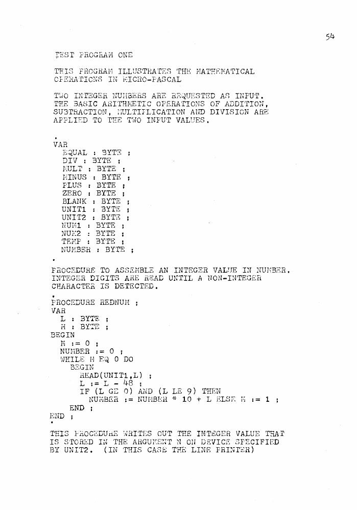
T.ES T F'EOG riA.I•l ONE
THIS FROGHAl>1 ILLUSTRATES rrHE HATHEI•IATICAL O}ERATIONS IN 1~ICRO-F'A3CAL
T\JO INT'~;GER NUIT3ERS ARE REQUESTED AS INPU·r. TEE BASIC ARITHI·~ETIC OPERATIONS OF .ADDITIO~J, SU3TMCTION, IiULTIFLICATION AND DIVISION ARE APFLIED 'I'O THE Tl·lO INPUT VALUES.
VAR EQUAL : BYTE ; DIV : BYTE ; EULr : BYTE ; HINUS : BYTE: ; PLUS : BYTE ; ZERO : BYTE ; BLANK : BYTE ; UNITl : BYTE ; UNIT2 : BYTE ; NUI,il BYrrE ; NUj\~2 : BY'TE ; TEI•iF : BY·rE ; NUIV:BEH : BYTE
PROCEDURE TO ASSEi·1BLE AN INTSGER VALUE IN NUNBER. I~JTEGER DIGITS ARE HEAD U!\TIL A NON-INTEGEii CF~RACTEn IS DETECTED •
• PROCEDURE REDNUM VAR
L : BYTE f.l : BYTE
BEGIN H := 0 ; NUHBER := 0 ; r,~EILE H EQ. 0 DO
END
B2GIN .i:1EAD ( UNIT 1 , L ) L : = L - LJ.S ; IF (L GE 0) AND (L LE 9) THEN NU~BER := NUMBSil * 10 + L ELSE ~ := 1
END
THIS :FnOCr::I:JU!iE ~.~RI'rES OUT THE IN'l1~~GER VALUE TRA·r IS S·l'ORED IN THE AHGUi·:ENT N ON DEVICi~ SPECIFIED BY UNIT2. (IN THIS CltSE THE LI~JE FRI?~TER)
54

. FROCEDUHE \,JRTNUI'·1(N 3yrp-:~)
--.1.-1
'IAE. L : BYTE 1'1 : BYTE
3EGIN N := N I 10 ; IF ( 11 1'JE 0 ) T~-IEN '~';RTNUH (H) L : = N - ( i ~ * 10) + 48 ; ~:fRITE ( UNIT2 ,·L)
END ; 3EGIN •
ASCII CODES FOR CHARACTERS ARE SET UP FOR FEINTING PURPOSES.
~1UL·T : = 42 ; EQUAL := 61 HINUS 1 = 4 5 DIV := 47 ; BLANK := 32 ZERO := 48 PLUS := 43
UNITl IS THE KEYBOARD OR TI:Rr.IINAL AND UNIT2 IS THE LINE PRINTER.
UNIT! := 0 ; UNIT2 : = 1 ;
READ IN THE T~>JO NUNBERS NUI"ll AND NUH2.
READLN(UNIT1) B.EDNUH ; r~u.rr11 r = NUHBER ; REDNUi·: ; NUT·I2 : = NUi··IBER
ADDITION SEQUENCE
-W'RITE~(UNIT2, BLANK) lvRITELN{UNIT2) ; Tv-IR"INUH (NUNl) ; WRITE(UNIT2,BLANK) ~RITE(UNIT2,FLUS} ; WRITE(UNIT2,BLANK) -/;RTNUl'l ( NU r-12 ) ; 'tlRITE (UNIT2, BLANK) ;
55

iJiRITE (UNIT2, EQU.AL) ; T;JRITE ( UNIT2 'BL&~K) ; TEHF : = NUNl + NUH2 WRTiJUE( TEI1P) ; V!RITELN (UNIT2) ;
SUBTRAC'riCN SEQUENCE:
•
WRITE(UNIT2,BLANK) ; WRITELN(UNIT2) ; WRT~TUN ( NUHl) ; WRITE(UNIT2,BLANK) WRITE(UNIT2,HINUS) WRITE(UNIT2,BLANK) WRTNUH(NUI·12) ; WRITE(UNIT2,BLANK) WRITE(UNIT2,EQUAL) HRITE(UNIT2,BLANK) TEI1P : = NU F!l - NU I1I2 TJRTNUN( TENF) ; ~~RITELN (UNIT2) ;
~IDLTIFLICATION SEQUENCE
WRITE(UNIT2,BLANK) WRITELN(UNIT2) ; WRTNUl·'I( NUHl) ;
•
l~JRITE ( UNIT2, BLANK) WRITE(UNIT2,NULT) ; ~-IRITE {UNIT2, BL.Al'JK) WRTNUN(NUI-12) ; WRITE(UNIT2,BLANK) ; vlRITE ( UNIT2 , EQUAL) ; \vRITE(UNIT2, BLANK) ; TEMP := NUMl * NUM2 WRTNUI-1 (TEMP) ; ~.JHITELN (UNIT2) ;
DIVISION SEQUENCE
WRITE(UNIT2,BLANK) 'tl RITELN ( UNI'l'2) ; \.-TRTNU H ( NUHl ) ; WRITE(UNIT2,BLru~K) r.~RITE(UNIT2 ,DIV) ; WRITE (UN rr2 , BLANK) WRTNUN(NUIY12) ; H RITE (UN I ~r2 , BLA.l~K ) t.JRI'rE: (UNI T2, EQUAL)
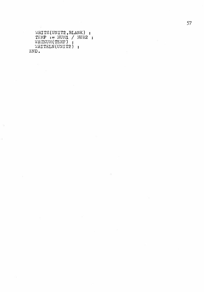
1wvRITE (UNIT2, BLANK) ; TEHP : = NUHl / NUN2 T Y.,-, :Tt'r\"'U"'~ ( Tl":'""!tP) w h ..i..h 1'1 .C.11l ;
~,JRI TELN ( UNI T2 ) END.
57

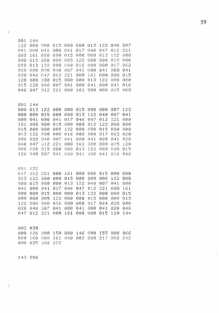
INTCODE Listing of Test Program One
~i 0 1 1 .::!. 4 010 005 040 001 040 001 040 001 040 001 040 001 840 001 848 001 040 001 040 001 ;:~1 •l· Ct :~i 0 t Ci ,: !· 0 0 0 :L •? 4 ~J 0 0 1 Ci 4 0 0 0 1 ~- 4 0 0 0 ~J 800 040 000 040 001 040 001 041 800 021 G00 810 041 000 020 000 021 001 800 010 041 800 100 141 000 000 000 000 014 123 021 000 007 001 000 007 041 060 062 021 000 007 801 000 007 041 000 105 001 000 007 041 811 103 063 141 000 000 000 000 021 041 012 063 001 000 007 061 028 000
001 144 021 140 000 150 041 001 821 000 010 140 000 057 143 040 000 040 001 044 021 000 012 040 004 040 001 040 001 001 000 012 041 012 064 021 000 014 001 000 014 041 000 101 141 000 060 040 007 041 001 041 600 041 814 046 047 012 221 000 161 140 000 242 001 000 812 001 000 014 041 012 063 062 041 060 061 021 000 013 080 000 015 001 800 013 122 143 041 052 020 800 007 041 075 020 000 005 041 055 020 000
o:211 144 010 041 057 020 000 006 041 040 020 000 013 041 060 020 000 012 041 053 020 000 011 041 000 020 000 014 041 001 820 000 015 000 000 014 121 221 000 037 000 000 021 020 000 016 221 000 037 000 000 021 020 000 017 000 000 015 000 000 013 122 000 000 015 120 040 007 041 000 841 000 041 016 046 047 012 221 000 161 GOO 000 015 000 000 013 122 000 080 015 000 000 011 122 000 000 815 000 000 013 122 040
001 144 001 041 000 041 000 041 817 046 047 012 221 000 161 000 000 015 080 000 013 122
Cl:Sl 041 1] 15
000 00!] ~~120
020 1 ~:: 0
!J1~:5 000 ~J13 L~:~
U00 020
~:j 0 (i 000 040
L~ ~ !::" ····' 1 ._.1
0(35 1 :2;2 000 01.6 007 O·::J. 1 ;221 i2iO~J
000 ODO
~:100
000 001~1
u;1 013
01~10
000 041
015 017 000 000 000
000 015 12J 040 807 041 800 041 000 041 816 046 847 012 221 ·000 161 800 000 015 000 000 013 122 000 000 015 000 000 010
58
001 144 1 .--.. -, ' c. t::
041 008 J00 015 000 000 013 122 040 007 800 041 000 041 017 046 047 012 221 161 000 000 015 000 000 013 l~~ 000
013 000 ~~=~oo
020 000 820 040 007 041 000 041 000 041 0 :2 0 0 4 iS C:! ,::j. 7 0 1 ;2 ;~:: 2 1 ~~~ 0 0 J. 6 1 0 0 0. 0 t;3 0 0 1 5 120 000 800 015 000 000 013 122 000 000 015 120 040 007 041 000 041 000 041 016 046 047 012 221 000 161 000 000 015 000
0(11 144 000 013 122 000 000 015 000 000 007 122 000 000 015 000 000 013 122 040 007 041 000 041 000 041 017 046 047 012 221 000 161 000 000 015 000 000 013 122 000 000 015 000 000 005 122 000 000 015 000 000 013 122 080 000 016 000 000 017 063 020 000 020 040 007 041 000 041 000 041 020 046 047 012 221 000 161 000 000 815 120 000 000 015 000 000 013 122 000 808 015 120 040 007 041 800 041 000 041 016 046
o:J 1 1 :~:2 047 012 221 000 161 000 000 015 000 000 313 122 000 000 015 000 000 006 122 000 000 015 000 000 013 122 040 007 041 000 041 000 041 017 046 047 012 221 000 161 000 000 015 000 000 013 122 000 000 015 000 000 005 122 000 000 015 000 000 013 122 000 000 016 000 000 017 064 020 000 020 040 007 041 000 041 000 041 020 046 017 012 221 000 161 000 000 015 120 144
t;:HL:: 030 000 126 000 150 000 146 000 155 000 066 080 160 000 161 040 002 000 217 000 242
··::- .. 7 •") .:..1.:.....
14:3 000
59

RESULTS
:24 .• 1~::: ··-· ;2
Test 2
This program performs an arithmetic sort on ten
positive integers. These ten values are less thfln 256,
separated by a non-numeric character end input from the
keyboard.. The program echo-prints the ten input values
end follows with a sorted display of the numbers in
ascending order.
60

THIS PROGRAH SORTS INTEGER VALUES IN ASCENDING ORDER. THE USER PROVIDES THE TEN INTEGER VALUT~S TO BE SORTED.
VAR
3LAIJK : BYTE ; nos : ARRAY (1 •• 10) OF BYTE 1JNIT1 : BYTE UNIT2 : BYTE IJ BYTE ; CH : BYTE ;
~rHIS PROCEDURE READS IN INDIVIDUAL INTEGER DIGITS UNTIL A NON-INTSGER IS DETECTED. THE INTEGER NUl•lBER IS ASSEHBLED IN LOCA'riON CH.
PROCEDUD.E REDNUr.I VAR
L : BYTE N : BYTE
SEGIN E := 0 ; CH : = 0 ; 1tJHILE Iii E Q 0 DO
BEGIN R~;AD(UNITl, L) L := L - 48 ; IF {L GF.; 0) AND (L LE 9) THEN CH : = CH * 10 + L ELSE
H := 1 END
END ; •
THIS PROCEDURE HRITES OUT THE I~JT'EGER VALUE THAT IS STORED IN LOCATION N. TEE NUHBER IS :·JRITTEN TO TIIE DEVICE CORRESPO~·~DIIJG TO UNIT2.
PROCEDURE ~·JRTNUH(N VAil
L : 3YTE ft1 : BYTE
BEGIN fr'~ ! = I'J I 10 ;
BYT"C;)
IF (I,l NS 0) THEN :JnTNUH(E} L := N - (M * 10) + 48 ; ·,,ii-iiTE (UNIT2, L)
2ND

THIS FnOCEDURE SORTS ·rHE INTEGZRS IN ARRAY NOS INTO ASCENDING SEQUENCE. THE CURRENT II·~PLE:NENTATION SORTS 10 NU!'~BERS.
PROCEDURE SORT VA..-q
K : BYTE ; J : BY'rE ; I : BYTE ; TE!•lP : BYTE
BEGIH J:=l; HHILE J LT 10 DO
BEGIN I := J K := I ; \.JHILE K LT 10 DO
BEGIN
J END
K := K + 1 ; IF NOS(I) GT NOS{K) THEN
END
BEGIN TEMP : = NOS(K) ; NOS ( K ) : = NOS ( I ) NOS(I) := TEMP ;
END ; . , := J + 1 ;
END BEGIN •
UNIT1 CORRESPONDS TO THE KEYBOARD OR TERNINAL AND UNIT2 CORRESPONDS TO THE LINE PRINTER.
•
UNIT1 := 0 ; UNIT2 := 1 ; BLANK:=32; READL1\T(UNIT1) IJ := 1
THIS LOOF READS IN THE TEN INPUT INTEGERS AND STORES THEN IN THE NOS AHRAY.
62
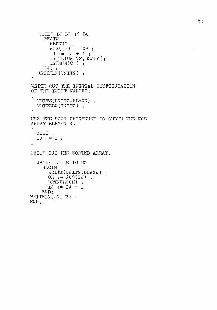
~EILE IJ L~ 10 DO BEGIN
REDNUM ; NOS(IJ) := CH IJ := IJ + 1 ; ~'!RITE ( UNIT2, BLANE) ; -,;RT:lUI·1 ( CH)
END ; ~V"RITELN(UNIT2) ;
~-JRITE OUT THE INITIAL CONFIGUP,ATION OF THZ INPUT VALUES.
:·.JRITE (UNIT2, BLANK) TATRII'ELN (UNIT2) ;
USE THE SORT PROCEDURE TO OHDER THE NOS ARR.A Y ELEf1EN~es.
SORT ; IJ := 1
WRITE OUT THE SORTED ARRAY.
HHILE IJ LE 10 DO BEGIN
WRITE(UNIT2,BLANK) CH : = NOS ( I J ) ; ~'J'RTNUI1 ( CH) ; IJ := IJ + 1 ;
END; '.I[RITELN (UNIT2) END.

INTCODE Listing of Test Program Two
no 1 1 ··~4 G<J 885 049 001 841 001 041 801 001 001 041 012 040 012 040 001 040 081 040 001 040 001 140 800 080 040 G80 840 001 040 001 041 008 021 008 010 041 000 020 000 027 001 000 01G 041 000 100 141 0CO 000 808 000 824 123 l21 000 007 001 000 007 041 060 062 021 000 007 001 800 0G7 041 080 105 001 000 JJ7 041 011 103 GSJ 141 080 000 800 000 127 041 012 063 001 000 007 061 020 000 027 140 000 142 041 001
01211 144 021 000 010 140 000 051 143 040 090 040 001 044 021 000 012 040 004 040 001 040 001 001 000 012 041 012 064 821 000 014 001 000 814 041 000 101 141 000 000 040 Oi2i'? 041 ;;:~ ;2 1 0 i~i 0
041 Oi2i0 12i41 Cl14
140 OFJO :23·:+ ~~!0 1 :~~46 047 0:!.2 00121 012 001 0 ;:; 0 0 6 1 0 ~:: 1 0.12: l:~·;::: 143
040 000 040 001 J40 001 840 001 040 001 0 4 :t 0 0 1 0 2: 1 ~:::1 0 0 Ci 1 0 0 0 1 : ::: 0 0 ~::1 1 0 0 4 1. 0 1 ~~
O!Zl J. 14·'+ 1!21;2 141 i2i0 1 000 0 L~ 102 [161 021
0 l 1 1. 41 •J00
021 000 007
001 000 OJ.O 000 007 OOJ. Ol~il~j 001 000 041 000 001
0~~1 000 011 noo oo·? 041 0~~17 041 001. 000 O:l1 124
041 001 124 067 000 000 006 124 070 041 800 041 004 066 041 000 041 006 066 044 041 000 001 080 007 124 041 001 124 067 000 000 006 124 070 041 ~00 041 004 066 041 000 841 006 066 044 184 141 800 000 041 000 001 000 007 124 841 081 124 867
e:o1 14·4 000 000 806 124 070 041 041 000 841 006 066 044 000 801 800 007 124 041 000 006 124 070 8·~1 000 000 041 006 066 J41 000 041 001 124 067 000 000 008 041 084 066 841 000 045 041 J~n 001 000 011 Ub( 000 J00 066 124 070
001 1>~ 1
0 !~J6 f:i 4 t !. ;~~ 4
041. 000 124
£J.::j.1
(l~~!4 066 O:i.2 041. 1,::1•;7 000 06;::: 041.
Cl J. 1:24 Ci?O t14l OE6 (:t44 c:ot 1~~4
Cl4l 0~~~4
64

0~31 144 l40 001
041
1:-, 1 ·:..· ... .!.
;,-:··:l'i ~- .l.
0 ::1 13 .-, ,:::: '
!2141 001 00!21 041 r~i ~~~l~~ 1:) .-, 7
~J ~~~ ~:;:1 :2i ~=: ~=·
!2101 144
1 4 ~~1 0 !J C1 3 .. ::· 0 eoo 010 140
001 :;~tOO
.i ... -, 1 :~:: 4].
001::. 1.24 1~'1 4 1 i/i 0 6 041 12:01 f:l C2i 0 Ci ~~~ 5
041 001 -t .·i.; .L"·I· .1.
02b 070 o .. _.t:.
061. L~~~
840 007 041 000 041 000 041 027 046 047 012 221 000 153 140 001 27~ 000 000 025 120 u0o 000 o~5 000 000 005 122 000 000 025 1~0 221 008 :b4 041 001 020 000 026 G00 000 0~b 041 01~ 103 141 000 0J0 000 000 025 000 ~08 005 122 041 000 080 G00 02b 124 841 001 124 0b7 000 880 0~6 124 0t0 041 000 041 804 066 041 000 0~1 006 !366 044 0,~.0 000 027 04f1 00 I 041 o~~~o 041 000 041 02, 046 047 012 221 000 1~- 008
001 020 000 026 041 001 061 020 000 026 140 002 034 000 000 025 120 144
[1(12
~:;:1 (.H3 ~~10 IZ1
~~:1 0 1 001
f:i54 120 152
~3~30
OfH]
040 IJ01 24:~~ OOCi
142 000 140 000 147 000 060 153 040 002 000 211 000 234 ::~ 2 3 o 0 o .:.. 3 , o o 1 :~. 2 t::; o o 0 ._. 1 ::~ 027 801 24~ 801 ~02 802 005
0 !::-1 2 0 4 3 ;J 0 :2 l 4 .:..
1 ,,:;. - 000
65

RESULTS
_0 43 52 9 8 7 1 3 1 734 2
2 3? 8 9 ·-~0 43 ~--~--... ~-~ -?34
66

CHAPTER 6
SUHHARY
Project work preceded smoothly while the
Hewlett-Packard machine was operating properly. Disc
problems arose on two occasions delaying progress in the
middle stages of the project. My implementation of the
interpreter on the HP2100 closely followed the initial
writing and debugging of the Hicro-Pasca.l ra.chine by
I•'Iark Green. During this time instructions were
understandably added and changed as problems in the compiler
were solved. A minor problem arose due to the incomplete
documentation of the Hicro-Pasca.l :tr:a.chine. ·rhe exact
nature of the input stream was left unspecified in the
interpreter description. This oversight was not recognized
until the latter stages of the project. Input routines
had to be redesigned and implemented so the interpreter
would accept programs in the form output by the compiler.
Since the Micro-Pascal I~chine is a rather new
concept, test programs are currently in short-supply. The
intermediate code instructions were individually tested
but the interpreter performance on larger programs was not

extensively probed. A number of compiler errors ~-1ere
uncovered during the debugging of the two test programs
found in chapter five.
There are about four hundred words a-llocated to
literal messages and summaries. Hany of these messages
could be pared down to representative numbers and some
descriptive statements concerning the interpreter excised
entirely if the interpreter size had to be decreased.
The current input capabilities are limited to keyboard,
paper tape and card access while output is set up for the
keyboard and the line printer. Other features in the
input/output package such as disc reads and writes could
easily be added when desired.
The size of an HP2100 word is sixteen bits or two
bytes. In my stack implementation there are two bytes
allocated for each stack item where in the ideal case one
byte would do. By doing this I can bend the rules of a
68
byte stack item so that negative values can be represented
in a normal HP fashion using sixteen bits the first of
which is a sign bit. Positive byte items are able to use
a.ll eight bits a.nd no special handling of negative byte
values is necessary. This was done only to permit convenient
implementation on the HF2100 and might not be appropriate
for other machines. In addition my experience with the
interpreter performance so far indicates that a stack size
of two hundred words would easily handle program executions.
This would mean a maximum of one hundred wa.sted words. In
the light of these arguments the implementation of a one
byte stack is not yet warranted.
The execution speed could be increased by partially
or entirely microcoding other interpreter routines.
Instruction group categories and specific instructions
within given groups can be easily added. The maximum
number of groups and instructions per group a.re each
limited to fifteen.
Conclusion
The interpreter is the key piece of software in
the Micro-Pascal compiler-interpreter system. Once the
compiler is wr1 tten in r·1ICRO-PASCAL 1 t can be self-compiled
into intermediate code. When an interpreter is established
on a host machine the Micro-Pascal system is readily
available.
HICB.O-PASCAL was designed as a basic high-level
language for use on mini and micro processors. Once
I1ICRO-PASCAL is implemented and debugged there are plans
to make it concurrent.

70
MICRO-PASCAL, as currently implemented, has a
very limited source language instruction set. Compiler
implementation has not reached the stage where strings can
be successfully handled. Their complete implementation
will contribute greatly to the usefulness of the language.
The availability of more and varied control statements
would improve language flexibility and ease of use.
The interpreter code is fairly readable using
comments liberally to indicate the flow of control.
Subroutines invoke a modular design which contributes to
an efficient program with minimized redundancy. If errors
are detected during interpreter execution the user is
provided with valuable information not contained in an
error number alone.
Work on this project has certainly given me a
better understanding of portable le.nguages. Ny experience
with the STAB system brought to light the importance of
good language and program documentation. If programs are
to be portable they must be precisely described in order to
be understandable and modifiable.
I have also acquired a better understanding of
terminal programming, edittlng and file management.
During the disc problem phase of the project I learnt the
hard tvay that files should a.lWAYS be well backed up for
security against machine failure and other mishaps. The
documentation process was a good disciplinary exercise
illustrating an important yet unglamorous aspect of a
complete program.
71

APPENDIX A
Running The Interpreter
This appendix describes how to run the interpreter
with microprograms. The commands input by the user are
underlined and described where appropriate. The statements
in capital letters are system comments.
:JOB,DB04
:PR,DBTST
- begin interpreter execution
BEGIN •DEBUG' OPERATION
H,10400
- base address for loading of program in core
- run the program
HICRO-DF.BUG EDITOB.
COEHAND? LOAD
- load the microprogram
ENTEH. FILE NAr•:E DBHPl
- nF.tme of file where microprogra.ms 8re stored
CG EI'·1AND? E, 0
- begin to execute the program from the beginning
72

START OF HICRO-FASCAL INTERFfiETER
THE UNIT NUHBERS FOR I/0 ARE
- these unit numbers refer to 1/o during program
execution
IN:FUT
OUT:FUT
0 - CRT
1 - CARDS
0 - CnT
1 - FRINTER
OUTPUT CAN BE DIR::I:CTED
CRT - ENTER A
FRINTER - ENTE.a A
AS SPECIFIED - ENTER A
TO
1 BELOH
2 BELOH
0 BELOH
IN PROGRAH
') 0 or 1 or 2 DBTST SUSP
OR
OR
73
- the interpreter is now waiting for the user to specify
the origin of source program input. The current
implementation permits three options:
2 - USER DISC
5 - CAHD HEADER
10 - PAPER TAPE (default option if unit number is
not 2 or 5)
:GO, unit number
program execution

74
summary of pro~ram execution
- this includes the number of instructions executed,
the maximum stack size and the program size in bytes.

AFFENDIX B
Listing- of HP n1croproP:rams
7S

76
~ MICROPROGRAMS FOR MICRO-PASCAL INTERPRETER.
::: l.1.l R I T T :::: r·~ E: 'l D (! 1•,•
1 E B ~~ r·~ D \' * DATE - AUGUST 1977.
:·l·:
*-----------------------------------------------------------
::::op I G I i-.1::::: 1 !]06
77
:·!·:
:+:
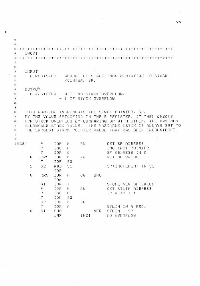
~=++++++++++++++++~++++++++++++++++++++++++++++++++++++++++++
:+: I r-iP UT ~ B REGISTER - AMOUNT OF STACK INCREMENTATION TO STACK ····· P 0 I i··~ T E P .. ~:; F' .
=+= OUTPUT * 8 REGISTER 0 IF NO STACK OVERFLOWJ * - 1 IF STACK OVERFLOW
* :+:
* THIS ROUTINE INCREMENTS THE STACK POINTER, SP, :+: B 'r' T HE \·' 1::~ L U E ~:; F' E C I F I ED I H T !-1 r:: B P E G I ~:; T E R . I T T H E t·~ CHECKS ° FCR STACK OVERFLOW BY COMPARING SP WITH STLIM, THE MAXIMUM
AL.LOWABLE STACK VALUE. THE VARIARLE MSTCK IS ALWAYS SET TO * THE ~ARGEST STACK POINTER VALUE THAT HAS BEEN ENCOUNTERED.
p I OF.: r•! F.: i.d GET ~:; F' I~D.DF:E::::~::
F' I f..l!-. F' I 1·1c T 1··1::;T PO I t·-ITEF.: f 'I 1-· J.
T I ()F.~ C:! ::;p ~i .D D P 1:. ~:; ::; I t·1 C! G! !? F::!:; I OP r··1 r:: r .• J GET ~=: F' '·.·'1~LUE
T I o~: .-.. -, ·=l.::.
•• NO ·-t I:::I:DD ~=; 1 ~:::p + I r··l C P E i'r E !··~ T J: I··~ ,-. 1 ·=· t::. .::.
I Ol? r::: F.:::; I 01:;;: 1'1 CJ .• J Ur·4C
I or.;;: ,-. ·=) 1 I OP T :::TOPE t··!EI.d .-·rr .::·1- 'v'::::1LUE F' I CIP i"·1 l?l .. .i C:iET :::TL I i"'r ~~~ :D D F: E ~:: ~:; p I nc D 1 p ·-- I p + l I
T I Cl r-::: ~3 ~:: t-· .-. I :::r r:: 1"·1 Pf.r.l -::~ ~:~-
T I C:i F;: 1::1 ::::TL I t·1 I t·~ (:! F::EG ,-·. 1 :::1 ...IU I··~EG ~::TL I t·1 - ::;p ·=t
._rr•!P I f··~C 1 i·iO 0\.' CI?F L OI.,J
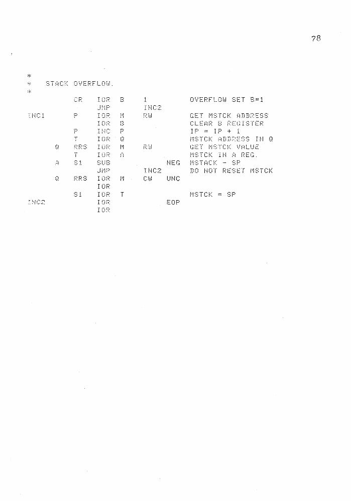
* STACK OVERFLOW.
I r·~C 1
:~ :·-.JC:2
.-. l
PP:3 I or;;: !'·1 IOP
~=:;! IC:r? T I !]P
I o;:::·
1
F: !,,J
O'·.·'EPFLOI.,J ::;ET B= 1
GET MSTCK ADDRESS C L. E ~~ l? E: P E c:; I S 'f E P IP == IP + 1
NEG MSTACK - SP INC2 DO NOT RESET MSTCK C!.,J Ut·4C
t·1:::;TCK = :;:;p EOP
78

J
:f:
:i·· -~ .. ·-~-· -;- ~-- -:- ·i-- + -~- -i- ·? + ~- + + + -r -:-· + -~ .. ·+-+++-I--!~ -1- -r- -r- ~- -:·· + -1· + + + + ~- -t- -r -r- + ·{ .. ;- + -1- ·r .. i. -~ .. + ·1- + -! .. -r ··1- + -f- + -r- +
:+: DEC::::T
· ~-: I l··1 P U T * 8 REGISTER - AMOUNT OF STACK DECREMENT
:-:·: 0 U T F' l .. r T
:+:
* DEC:ST
E ~-~DDC
8
(i
1
P IOR f·1 F' It·! C P T IOR 0 r-;.:F.:S IO~: :::1
I OR ~~
F:: P ::: I Ci F: 1"·1 T IO? :=:1 t'~tDD B FRS I 0~: 1··1
IDR RF.:S IO:? T
Jt•iP
IHC A ._1 i·1 p IOP I OF:
NO STACK UNDERFLOW ::: T (1 C t< U i··-i DE~: F L 0 1.•.1
f?l.d
Cl.t.l
E!··-IDDC
El··iDDC
GET ::;;p ADDF.:ESS I J··i C I t·~ :::; T . F' 0 I ti T E R ADDP. ::;;p I H C! :::: T 1:::1 C K D E C P . I l··i ::: 1 C L E ~:1 R r:::t R E G I :~; -~ E R G E T r.,.t ;~ L U E 0 F ::: P ::: P I t·i E:: R E G I ::: l E F.: S P -- !,/ ~~ L !_I E ( ::;; 1 )
UNC STORE NEW SP VALUE
NEG CHECK FOR UNDERFLO
~~ --
EOP
79

:+:
::-: + + + +· -:- + + --:- + + + + -:- + + + + + + + + + + + + + + --1· -{-· + + + + + + -{· + + + + + + + + + + + + + + + -:· + + + + + + +
*+++-~·~++~+++++++++++++++++-~+++++++++++++++++++++++++++++++++
:{·:
· •· B ;:.:: E G I S T E P -- I t·1 D E ;:.; 0 F D E ~:: I F.: E D r:~, P P A \' E L E 1·1 E t-~ T
:+: OUTFUT
~ A R~GISTER - DESIRED BYTE
:-f-:
GB'r'TE B
CR CLO A IOF: B ._lt·1P
I 0 r-;:: ~~~
IOF:: A I 0 F:: 0
I~-~ C B CF::::; B
377 MASK WORD IN A REG 0 D D I :::; I t·i J:! E ::-:: 0 D D
NXT INDEX IS EVEN SET OVF~AL~ IN IR I~LF
i~LF
It·HrE>< + 1 r:. I r·i TJ E ::·:: + 1 ) . ...- 2:
* LOCATE THE STARTING ADDRESS OF THE ARRAY. :f:
F· I OR t-1 F:I .. J GET ~: F:: i? (1 \' ,-:, Tl D P E ::;; ::;; p I HC F' I t·iC I >-i:3TP PO I t·-!TER T I 01? ,-. 1 r:iDDPES::; c I '..·'E::: '·/ALU -:~
,-. ·=· 1 I D F.: t·1 F.: hi T I o;? , ..... -. . ::·~
B ,-. .-1
·=·~ ,:::,nn :::; =~ ~:;3 I -·
iF~: 1"•1 Pi.~.l , __
T I CIF: ::::4 0 :::4 (J!""iD (i O'·.•'F
..Ji"·IP E 1·-~ D CiT :+:
:+: t·l 0 '·.·' E E: \' T E T 0 THE L 0 hiE P F' 0 f~: T I 0 t·i 0 F ~1 P E G I S T E R . :t:
EHDCT
A ;:::r
IOR IP IOP A I :=~ l? ~~
I CIP I() F~
27
EOF'
ASSEMBLE ALF INST. (iLF (:1LF
80

APPENDIX C
This appendix contains test programs that can be
used to verify the correct operation of the interpreter
instruction set. Each program tests an instruction group
or groups. Most of the programs have a step by step
description of their operations included. It is assumed
these test programs will be used with some type of
debugging package so that stack contents and
variables can be periodically sampled. This
elegant but it is painfully precise.
ARITH
001 051
041 004 060 041 007 061 041 001 -002 063 041 002 064 041 000 041
041 000 041 011 066 041 000 041
041 000 041 006 070 041 000 041
144
143 000
1 - Load 4 onto the stack and negate it
2 - Load 7 onto the stack and add it to -4
to give 3
J - Load 1 onto the stack and subtrAct it
from 3 to give 2
81
relevant
may not be
062
003
002
004
060
061
062
041
Q§j
Q§:z_
QZ.1
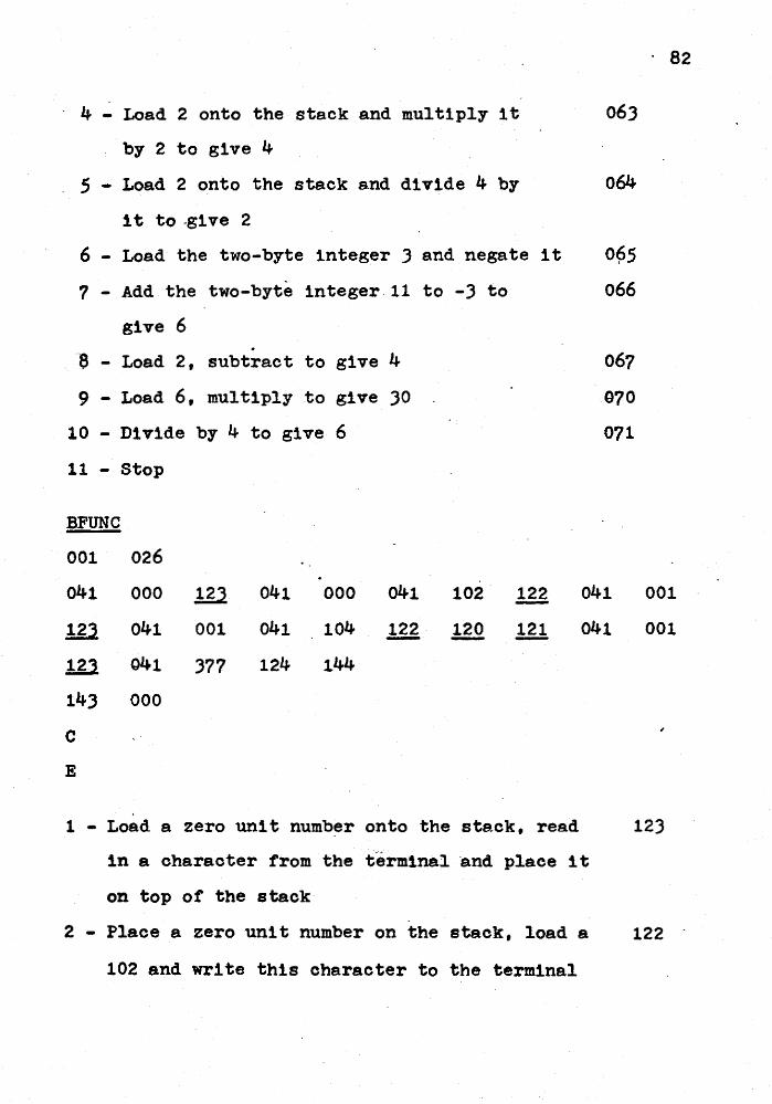
4 - Load 2 onto the stack and multiply it 063
by 2 to give 4
_ 5 - Load 2 onto the stack a.nd d1 vide 4 by 064
it to -give 2
6 - Load the two-byte integer J and negate it
7- Add the two-byte integer.ll to -J to
give 6 .
. 8 - Load 2, subtract to give 4
9 - Load 6, multiply to give JO
10 - Divide by 4 to give 6
11 - Stop
BFUNC
001 026
041 000 ill 041 000 041
123 041 001 041 104 m 12'3 041 377 124 144
143 000
c E
102 122
120 121
065 I
066
067
970
071
041
041
. 82
001
001
1 - Load a zero unit number onto the stack, read 123
in a character from the t-erminal ·and place 1 t
on top or the stack
2 - Place a zero unit number on the stack, load a 122
102 and write this character to the terminal

J - Load a 1 and read a character from unit 1
(in this case the card reAder)
4 - Load 1 and 104 and send 104 or the ASCII
character D to the line printer'
5 - The current output line is terminated and
D is printed on the line printer
83
123
122
120
6 - Terminate reading from the current line and 121
reset the read pointers
7 - Load 1 and read a character from the card 123
reader to the top of the stack
8 - Load 377 onto the stack then move 377 to 124
SF + 1 while a zero byte is inserted at SF
9 - Stop
LOAD + STORE
001 011
041 004 000
143 000
000 001 000 000
144
144
1 - Load a 4 onto the stack at location one, 041
STACK(l) = 4
2 - Load the element stored a.t STACK( 1) onto the 000
stack top, STACK(2) = 4
3 - Store the top staclr element at STACK( 0) 020
4 - Stop 144

84
LOGIC
001 310
041 005 041 005 100 041 005 100 041 005
041 005 101 041 005 101 041 003 102 041
004 041 002 102 041 000 102 047 002 041
005 041 005 1Q1 041 005 1Q1 041 000 1Q1
041 005 041 005 104 041 003 104 041 004
041 002 104 041 001 1.9.2 041 000 1.9.2 041
003 ill 047 002 041 000 041 001 041 000
041 001 106 041 000 041 001 041 000 041
002 106 041 000 041 002 041 000 041 001
1Q1 041 111 041 112 041 111 041 112 1Q1
041 000 041 002 041 000 041 004 110 041
000 041 002 041 000 041 001 110 041 000
041 002 041 000 041 002 110 041 000 041
002 041 000 041 004 111 041 000 041 002
041 000 041 001 111 041 000 041 002 041
000 041 004 112 041 000 041 002 041 000
041 001 112 041 000 041 002 041 000 041
002 112 041 000 041 002 041 000 041 004
111 041 000 041 002 041 000 041 . 001 ill 041 000 041 002 041 000 041 002 llJ. 144
143 000

Testing One-Byte Commodities
1 - Test 5 EQ 5 which results in a 1 (true).
and test 1 EQ 5 which results in 0 (false).
2 - Test 5 NE 5 - false and test 0 NE 5 - true.
J - Test 1 LT 3 - true, test 4 L·r 2 - false
and test 0 LT 0 - false.
4 - Decrement the stack pointer, SP by 3.
5 - Test 5 LE 5 - true, test 1 LE 5 - true
and test 1 LE 0 - false.
6 - Test 5 GT 5 - false, test 0 GT 3 - false
and test 4 GT 2 - true.
7 - Test 0 GE 1 - false, test 0 GE 0 - true
and test 1 GE 0 - true.
8 - Decrement SP by 2.
Testing Two-Byte Commodities
85
100
101
102
047
103
104
105
047
9 - Test 1 EQ 1 - true and test 1 EQ 2 - true. 106
10 - Test 2 NE 1 - true and test 107
44512 NE 44512 - false.
11 - Test 2 LT 4 - true, test 2 LT 1 - false
and test 2 LT 2 - false.
12 - Test 2 LE 4 - true, test 2 LE 1 - false
and test 2 LE 2 - true.
13 - Test 2 GT 4 - false, test 2 GT 1 - true
and test 2 GT 2 - false.
14 - ·rest 2 GE 4 - false, test 2 GE 1 - true
and test 2 GE 2 - true.
110
111
112
113

1,1ANIF
001 052
040 004 041 377 042 004 004 101
104 043 003 000 000 006 044 043
000 005 077 045 043 003 001 000
04? 003 043 006 000 000 002 000
oc;o - lli 144
143 000
1 - Increment the stack pointer by 4 to 4.
2 - Load a 377 onto the stack at SF = 5.
3 - Store the character string ABCD onto the
stack, that is 4, 4, 101, 102, 103 and 104.
102
004
005
000
86
103
000
046
005
040
041
042
4 - Load 3 bytes onto the stack O, 0 and 6. 043
5 - Load the byte at SF = 6 onto the stack, 4. 044
6 - Load 4 bytes onto the stack 0, 0, 5 and 77. 045
Store 77 at stack location 5.
7 - Load 3 bytes 1, 0 and 5. Convert this o46
three-byte relative stack address to a
two-byte absolute stack address preceded
by a zero byte.
8 - Decrement the stack pointer by 2.
9 - Load O, 0, 2, 0, 0 and 5. Load the contents 050
of stack element 5 at SF - 2 and stack
element 6 at SF - 1.

10 - Store 4 at stack location 3 and 77 at
stack location 2.
11 - Stop
FCALL
001 015
041
041
001
004
143 000
041
143
002 000 012 041
1 - Load 1 and 2 onto the stack. Call a
procedure and thereby create a seven-byte
header.
Byte 1 Old L\TL = 0
Bytes 2 + 3 Return Address = 6
Bytes 4 + 5 Add. of Ftn Result = 0
Bytes 6 + 7 DSPLY For Old LVL = 0
Also set DSPLY(l) = 2, set LVL to 1 and
instruction pointer IF = 11 (which will be
immediately incremented to 12)
377
87
051
144
220
2 - Load 4 onto the stack to show we have reached 041
the right spot.
J - End the procedure which
Restores LVL to DSPLY(LVL - 1) = 0
Resets IF to 6
Resets the stack pointer, SF to 2.

88
4 - Load 377 onto the stack to show the proced~re 041
has concluded correctly.
5 - Stop
I' HANS
001
140
041
003
002
056
004
002
114
077
143
122
000
001
142
000
041
142
000
041
144
000
OOJ
141
001
046
06J
001
104
063
041
000
000
041
140
000
041
140
000
021
036
062
000
074
062
000
141
041
041
140
061
041
140
117
000
002
061
000
377
061
000
377
012
041
140
061
000
140
117
000
041
001
000
003
000
000
003
000
144
002
041
061
000
041
117
000
041
1 - Pass control to instruction 3 in that IP is 140
set to 2 before 1ncrementat1on.
2 - Load a zero (false) onto the stack. Execute 141
e conditional jump on the top stAck element.
Since this element is false control jumps to
IF = 12 so that 041 002 will not be executed.
3 - Load a one (true) onto the stack. In this
case the conditional test fails so th&t a 2
should be loaded onto the stack.
141

4 - Load 1 and 3 onto the stack. Perform a
case statement based on the top stack
element J. There are 3 c~se elements 1, 2
and J so there should be a match with the
third. element. ~rhis will ca.use t=l load of
63 to occur.
5 - Load 4 onto the stack. Perform the same
case statement on 4. There should be no
match with the case elements 1, 2 or 3. The
next instruction to be executed should be a.
load of 077 onto the stack.
6 - Stop
89
142
142
144
Note - 143 is a procedure return and is tested with the
procedure call in FCALL.
Test Of Error Messages
1 - Illegal Level Number
001 003
117
143
000
000
144
2 - Illegal Group Number
001 003
160 000 144
143 000
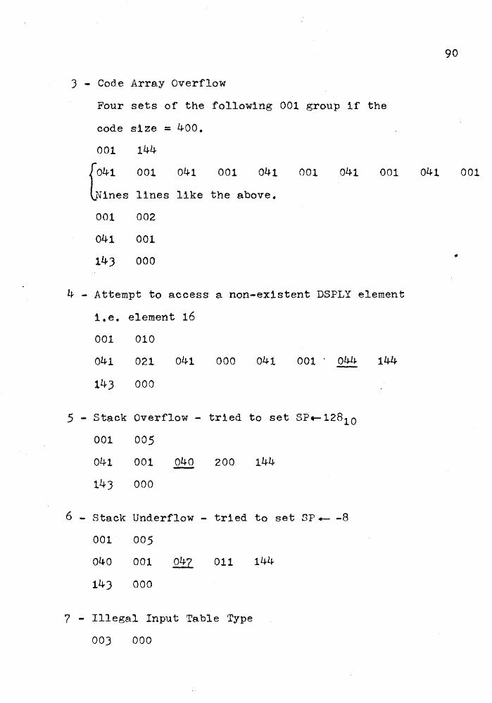
3 - Code Array Overflow
Four sets of the following 001 group if the
code size = 400.
001 144
[041 001 041 001 041 001 041 001
Nines lines like the above.
001 002
041 001
143 000
4 - Attempt to access a non-existent DSPLY element
i.e. element 16
001 010
041 021 041 000 041 001 . 044 144
143 000
5 - Stack Overflow - tried to set SP.-12810
001 005
041 001 040 200 144
143 000
6 - Stack Underflow - tried to set SF +- -8
001 005
040 001 047 011 144
14J 000
7 - Illegal Input Table ·rype
003 000
90
041 001

BIBLIOGRAPHY
Boon, C. High Level Languages. Berkshire, Englanda Infotech Info Ltd, 1972.
-Goos, G., and Hartman1s. Lecture·Notes In Computer
. 91
Science, Software Engineering - An Advanced Course. New York: Springer - Verlag, 1973.
Gries, David.· Compil.er Construction For Digital Computers. Torontoa John Wiley and Sons, 1971.
Hewlett-Packard. Assembler Referen.ce Manual. CUpertino, California: Hewlett-Packard Compa;ny, 1972.
Hewlett-Packard. Microprogramming Guide For HP2100. CUpertino, California: Hewlett-Packard· Company, 19?&.
Hewlett-Packard. Microprogramming Software For HP2100, CUpertino, Californiaa Hewlett-Packard Company, 19?).
Solntseff, Dr, N. • A Pascal 6000 Primer. Hamil ton: Applied Mathematics Department, 1975.
Wirth, N1klaus. Algorithms and Data Structures = Programs. Englewood Cliffs, New Jersey: Prentice-Hall- Inc.,
. 1976.
REFERENCES
GBE. Private Communication with Mark Green, 1977.