Embed Size (px)
Citation preview
SERBIAN JOURNAL OF ELECTRICAL ENGINEERING Vol. 9, No. 1, February 2012, 71-80
71
A Methodology for Testing Complex Professional Electronic Systems*
Nemanja Paunović1, Jelena Kovačević1, Ivan Rešetar1
Abstract: This paper presents a testing methodology for complex professional electronic systems, based on automation and black box testing, divided into 4 testing phases. The goal is full automation of the testing process, making the process of testing as reliable as possible, and cutting testing time and human interference to a minimum. Testing is performed during production, with an emphasis on the functionality of the device. All verifications must be executed before the device is launched on the market.
Keywords: Black Box Testing, Automation, Testing.
1 Introduction Nowadays, the development of complex professional electronics systems is
constantly expanding. The goal of every manufacturer is to put their product on the market as fast as possible and offer it to the customers, but on the other hand, short production time should not affect the quality and reliability of products. The modern devices have a large number of functionalities, from the coupling of different interfaces to combining multiple devices into a single device. Examination and testing of such complex systems has became a serious problem. During the development of devices that fall within the complex professional electronics system, more than 40% of the time is spent on verification and testing [1]. Due to the tendency of producers to ensure competitiveness on market, the development of this field is largely determined by the price on the one hand, and justified need for shortening of time of products appearance on the market, on the other. Together, these two factors tend to reduce overall systems development time. In practice, shortening of development time is achieved by shortening a testing process. In conditions of expansion of systems functionality, reducing costs in this way leads to a short-term results and not fully tested product followed by degradation of quality that negatively affects the competitiveness. To ensure shorter production time and to
1University of Novi Sad, Faculty of Technical Sciences, Trg Dositeja Obradovića 6, 21000 Novi Sad, Serbia; Emails: [email protected]; [email protected]; [email protected]
*Award for the best paper presented in Section Computer Engineering and Informatics, at Conference ETRAN 2011, June 6 – 9, Banja Vrućica – Teslić, Bosnia and Herzegovina.
UDK: 621.3.011.7; 004.4:621.37/.38 DOI: 10.2298/SJEE1201071P

N. Paunović, J. Kovačević, I. Rešetar
72
provide better quality, more attention should be paid to the quality system analysis and the improvements of testing process.
We distinguish two testing types: - Testing as a final stage in the design and prototyping devices (QTP –
qualification test procedure): This testing confirms the correctness of the design and software of the devices. - Testing device in the production process (PTP – production test plan) This paper focuses on the PTP testing. Proposed method of testing of
complex professional electronics systems is divided into four phases that are part of the PTP testing. Emphasis is on the second phase, which is based on the black box testing method [3].
Phases of DUT (Device under test) testing: - hardware testing; - functionality testing; - stress testing; - robustness testing. Phases are executed sequentially, transition to the next stage is possible
only with positive report from previous stage. The advantage of this testing approach is that the sequential testing approach with a good test plan provides structured finding and fixing errors and gives exact results.
Device testing related with specified markets certification, requirements compliance and standards, are part of the QTP testing, but are not in the focus of this paper.
The proposed method is practically applied in testing device for collecting audio and video samples in real-time, labelled RT-AV100.
Further in the paper each of four phases will be described. The phase two will be emphasized and an example of applying proposed methodology on testing of a RT-AV100 device will be given.
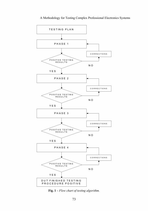
2 Proposal of Testing Methodology Fig. 1 shows a block flow diagram of the proposed testing methodology. In the process of designing device it is necessary to define a detailed test
plan. Test plan contains requirements that are based on the specifications of the DUT, a list of necessary equipment for test environment, a description of all scheduled tests and expected results of testing. As an input into each phase we are using the test plan, as the output from each phase we get a report about positively completed tests result and one where we have to repeat testing or report a bug. If some of requests have not passed testing it is important to use the system for bug/issue tracking system through which the test engineer reports that error was been found.
A Methodology for Testing Complex Professional Electronics Systems
73
T E S T IN G P L A N
P H A S E 1
P O S IT IV E T E S T IN G R E S U L T S
C O R R E C T IO N S
N O
Y E S
P H A S E 2
P O S IT IV E T E S T IN G R E S U L T S
C O R R E C T IO N S
N O
Y E S
P H A S E 3
P O S IT IV E T E S T IN G R E S U L T S
C O R R E C T IO N S
N O
Y E S
P H A S E 4
P O S IT IV E T E S T IN G R E S U L T S
C O R R E C T IO N S
N O
Y E S
D U T F IN IS H E D T E S T IN G P R O C E D U R E P O S IT IV E
Fig. 1 – Flow chart of testing algorithm.
N. Paunović, J. Kovačević, I. Rešetar
74
Depending on whether it is executed by QTP or PTP testing, bug report are addressed on research and development team (in QTP testing case) or to the production team (to the PTP technicians). When appropriate team corrects reported error it reports that error as fixed, then test engineer repeats phase on which he discovered error and stopped testing because of it.
2.1 Testing of hardware The first stage is to examine the correctness of device's hardware. The
examination of the printed circuit board, links on them, mounted electronic components, detection, verification and errors correction that may occurred during the manufacture.
The manufactured printed circuit boards are tested with the existence of electrical connections (expected value of 0 Ω of resistance at points with equal potential) and infinite resistance in different nodes (without mounted electronic components). Other measurements that can be made are following: the thickness of metallization layers, dimensions and cross section of the board, the characteristic impedance of lines, if required for specific interfaces, and more.
The next stage is assembling (soldering), where optical testing and x-rays are used ,to check whether the right components are set in the right place, and whether they are correctly oriented or there are bad solder, short circuits, etc.
Under present conditions of printed circuit board production, production is usually removed from developer’s firms, a physical examination of the boards can be ordered as a service, when delivered PCB has been already tested.
In the preliminary control functionality, coupling circuits and JTAG dongle can be used.
A part of testing procedures, which equipment is relatively economical and can be performed in laboratories without any special testing requirement, is a boundary scan. The boundary scan is the standard IEEE 1149.1 subject [3], also known as the Joint Test Action Group (JTAG). This standard is now widely used for integrated circuits testing. With this connection it is possible to access all digital interfaces in the device and it is the main way of embedded systems testing. What we need is PC software to establish communication with the subject of testing. The software also needs to be loaded into the DUT and a dongle that connects PC with DUT is also necessary. Loaded software provides system with self-diagnostic functionality and at the end of simulations it gives a report about which functional units have passed the test and which have not.
2.2 Functionality testing The second phase is testing of device software. After report on hardware
testing has been marked as a positive, we proceed to verify the functionality of the device. The complexity of this phase depends on the construction of the

A Methodology for Testing Complex Professional Electronics Systems
75
device. The most complex cases show up when DUT is designed as several sub-systems in one, if it has a different coupling of interfaces and different ways of connection.
Functionality testing is defined as an activity that is conducted to assess a quality of hardware and software of the system, for their own improvement, thru bugs and errors identification [5].
The test plan at this stage contains requirements that are prepared according to device specifications, description of the test environment that will simulate a realistic working environment of DUT, a detailed instructions of testing flow, which includes all the features supported by the DUT and an expected test result. Depending on the device purpose the acceptable tolerance on test result will be defined.
After an analysis of similar solutions on the market, as solution for software testing support RT-Executor has been selected, the application developed in research and development institute “RT-RK”, which supports testing according to the black box testing methodology. RT-Executor provides support for using a large number of devices with different purposes, e.g. device for processing audio samples, for a work with files / folders, for controlling external devices, generators of various audio and video signals, etc. [5]. RT-Executor application is fully customizable according to the environment. RT-Executor allows easy implementation of new devices. Black box testing method involves functional software testing and needs to know only what we pass on the system input and what we expect on the output. Based on the specifications of a DUT, test engineer writes a test to ensure that planned functionalities are executed properly. Tests can be written in BBT_SCRIPT language (dedicated scripting language) or in the language “Python”. Tests should be fully automated. For each engaging of test engineers, chances for errors and extended testing time are rising. The first thing that should be done is to set a reference files for comparison with test files. When tests, that cover the complete functionality of the DUT, are written and when correctness of tests is confirmed, the project that consists of those tests may start to run in the RT-Executor. The tests are automatically executed, and after their completion, it is seen what tests are positive, negative or unresolved. If it is necessary, tests that are not positive could be rerun. To get the test results it is necessary to set the range of tolerance considering the purpose of device. RT-Executor delivers the report which shows the tests results that can be transferred to the html file for sending, storing, or for keeping records. Fig. 2 provides an example layout of a test report in HTML format.
For tests that are “FAIL” or “INCONCLUSIVE” it is necessary to check the correctness of the tests and repeat them. To declare that the device has successfully completed it’s testing; all tests must be marked as a “PASS"

N. Paunović, J. Kovačević, I. Rešetar
76
(positive). If there are non “PASS” tests after checking the tests correctness and repeating it, test engineer report a bug, through the bug trucking system (such as Bugzilla or Jira).
Fig. 2 – Test report example.
2.3 Stress testing Stress test is the third phase. This phase aims to verify the stability of the
system when the environmental and other conditions differ from the nominal, defined by device specification. This phase involves testing beyond normal operation, often deliberate causing failure of device, in the interest or consideration of the testing results [6].
Test plan defines the environment in which the device should be tested, environmental conditions, test duration, depending on the purpose of the device and the expected test results.
RT-Executor also can be used during this testing phase. It has an option to automatically execute written tests numbers of hours. The advantage is reduced human (expensive and imprecise) involvement.
This testing is actually done in the QTP. In the production phase, sampling and some critical tests are repeated on the prescribed sample on each batch.
A Methodology for Testing Complex Professional Electronics Systems
77
2.4 Robustness testing The final phase of device testing is to examine working in the conditions
beyond nominal conditions, by improper use of the device, and the consequences of such situations. Robustness testing is defined as the degree to which a system or component can function properly in extreme conditions [7].
The content of these tests is determined in accordance with the analysis of risks and consequences of using DUT in an environment beyond the given conditions (FMEA - failure mode and effects analysis).
Test plan defines the environment in which the device should be tested, environmental conditions, test duration, depending on the purpose of the device and the expected test results.
Depending on the purpose of the device, most extreme and unexpected situations in which the DUT can be found have to be predicted e.g. dropping down the device, spilling liquids, rapidly cooling or heating device etc.
This testing is actually done in the QTP. In the production phase, sampling and some critical society are repeated on the prescribed sample on each batch.
3 Testing RT-AV100 Device The proposed methodology was applied in testing the device RT-AV100.
RT-AV100 is used in the TV industry for testing STB (set top box – a device used as a digital television signal receiver) device. The device is based on digital signal processor, and has numerous audio and video interfaces (HDMI (High-Definition Multimedia Interface), YPbPr, S-Video (Separate Video), S/PDIF (Sony/Philips Digital Interconnect Format) optical, S/PDIF coaxial, CVBS (Composite Video, Blanking, and Sync)). The device has the ability to connect to the network via 1Gb LAN (Local Area Network) port [8].
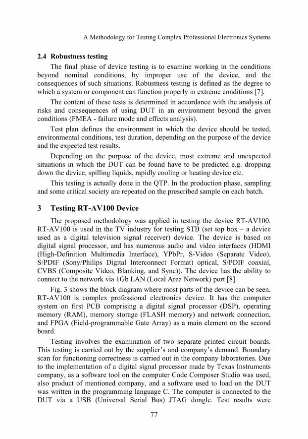
Fig. 3 shows the block diagram where most parts of the device can be seen. RT-AV100 is complex professional electronics device. It has the computer system on first PCB comprising a digital signal processor (DSP), operating memory (RAM), memory storage (FLASH memory) and network connection, and FPGA (Field-programmable Gate Array) as a main element on the second board.
Testing involves the examination of two separate printed circuit boards. This testing is carried out by the supplier’s and company’s demand. Boundary scan for functioning correctness is carried out in the company laboratories. Due to the implementation of a digital signal processor made by Texas Instruments company, as a software tool on the computer Code Composer Studio was used, also product of mentioned company, and a software used to load on the DUT was written in the programming language C. The computer is connected to the DUT via a USB (Universal Serial Bus) JTAG dongle. Test results were
N. Paunović, J. Kovačević, I. Rešetar
78
presented on a computer’s screen in the form of a list of components indicating “PASS” for the component which have passed testing as positive and “FAIL” for one which have not.
Fig. 3 – Block scheme of RT-AV100 device.
For testing the functionality of RT-AV100 it is requested to examine the
operation of all audio (HDMI, S / PDIF, LineIN) and video (HDMI, YPbPr, S-Video, CVBS) interfaces. The test environment consists of the generators of video and audio signals, which support all picture resolution and audio formats for all interfaces that device supports. Generator is connected to the device via audio and video cables, device and PC communicate over a LAN, and PC and generator are connected via RS-232 cable.
Example of checking HDMI video interface: test engineer prepares tests to be run on RT-Executor. Running test commands to video signal generator to transmit an image of certain resolution over the HDMI cable to the DUT, DUT also receives a command via RT-Executor to collect a picture, and RT-Executor gets a last task-to compare the collected image with a reference picture in the PC, with a tolerance of 10 pixels (which must not be grouped in a single block images). RT-Executor compares test samples to the reference and returns the comparing result in the format of report. The duration of each test is about 30 seconds. The same procedure is repeated for all other interfaces.
During stress testing of RT-AV100 device it was required that the device repeats cycles of collecting audio and video samples continuously over a period of 12 hours in the laboratory conditions.
The result of stress test was positive because even after 12 hours of continuous operation DUT has functioned properly, report results in RT-executor-a were all positive (PASS).

A Methodology for Testing Complex Professional Electronics Systems
79
Due to the construction and purpose of RT-AV100 device, there were not specific requirements for robustness testing on the DUT. On a proposal of test engineers, the device was tested by submitting audio instead of video signals and vice versa, LAN connection cable was physically interrupted during operation, then re-established after which the DUT continues to function properly.
Testing of a one RT-AV100 unit lasted approximately 20 hours and performed over 2000 tests in the RT-Executor. During the testing some of the problems were that the device didn’t collect images for some formats, captured pictures were not identical to the reference or the device could not operate continuously for several hours, but each of these problems had been reported promptly and effectively resolved.
4 Conclusion This paper represents the testing methodology of complex professional
electronics devices. It's divided into 4 phases that include testing of devices in the PTP phase. This approach is very reliable testing method, for its positive test result, it guarantees complete accuracy and reliability of the device. This method is based on the automation of the testing process as much as possible and using of black box testing method which all contributes to the faster testing and reducing the number of errors. The main advantage of this methodology is the precise path of discovering and fixing bugs.
The proposed methodology was proven during testing of audio-video grabber device, RT-AV100. Using RT-Executor, for 1 hour of testing, up to 120 tests were executed. Stress testing were the most time-consuming phase, and using our approach the total testing time was significantly shortened by reducing the time allotted for this phase.
Disadvantage of the proposed methodology is sequential testing organization that causing in the production process also sequentially load moving from the resource to a resource (both human and technical), which prevents their optimal use.
5 References [1] B. Korel: Automated Software Test Data Generation, IEEE Transaction on Software
Engineering, Vol. 16, No. 8, Aug. 1990, pp. 870 – 879. [2] D. Marijan, N. Teslić, M. Temerinac, V. Peković: On the Effectiveness of the System
Validation based on the Black Box Testing Methodology, Journal of Electronic Science and Technology of China, Vol. 7, No. 4, Dec. 2009, pp 385 - 389.
[3] IEEE 1149.1-1990 Standard Test Access Port and Boundary-Scan Architecture, IEEE, 1990. [4] A. Abran, J. Moore, P. Borque, R. Dulpis, L. Tripp: Guide to the software Engineering Body
of Knowledge, IEEE, 2004.
N. Paunović, J. Kovačević, I. Rešetar
80
[5] V. Peković, N. Teslić, I. Rešetar, T. Tekcan: Test Management and Test Execution System for Automated Verification of Digital Television Systems, 14th International Symposium on Consumer Electronics, Braunschweig, Germany, 7 – 10 June 2010, pp. 1 – 6.
[6] W.B. Nelson: Accelerated Testing - Statistical Models, Test Plans and Data Analysis, John Wiley & Sons, NY, USA, 1990.
[7] A. Kövi, Z. Micskei: Robustness Testing of Standard Specifications - based HA Middleware, International Conference on Distributed Computing Systems Workshops, Genova, Italy, 21 – 25 June 2010, pp. 302 – 306.
[8] http://www.rt-rk.com/audiovideo-capture-devices/navic.