Embed Size (px)
Citation preview

A MASTER’S GUIDE TO:
CONTAINER SECURING

CONTENTSVoorwoord / Introduction 3
Basic advice 4
Do’s and don’ts 7
Lashing systems 9
Safe working 12
Ships 15
Containers 21
Container construction 26
Lashing components 31
Principles of stowage 36
Ship’s behaviour 46
Consequences of failure 51
01 02 03 04 05 06 07 08 09 10 11 12
2 / CONTAINER SECURING / NNPC

01 vOORwOORDDe NNPC heeft zich ten doel gesteld haar loss prevention beleid aan te scherpen. Een van de onderdelen van dit beleid is het beter informeren van leden over specifieke loss prevention onderwerpen om hiermee schadeclaims te voorkomen. De herverzekeraars waar de NNPC nauw mee samenwerkt beschikken over een reeks aan loss prevention publicaties die ook voor NNPC leden relevant zijn. De NNPC heeft van The Standard P&I Club de rechten verkregen om hun publicaties ook aan NNPC leden aan te bieden. We hebben er voor gekozen, gezien de Engelse terminologie die in de praktijk vaak wordt toegepast, de publicaties vooralsnog in het Engels aan te bieden en niet te vertalen naar het Nederlands.De eerste NNPC Master’s guide die we publiceren heeft als onderwerp Container Securing. Het doel van deze Master’s guide is de do’s en don’ts bij de bevestiging van containers aan de orde te stellen en het geven van adviezen om hiermee schades terug te brengen dan wel te voorkomen. Het streven is dat er op termijn meer publicaties gaan volgen.
An improved policy on loss prevention is one of the objectives NNPC has decided to aim for. This includes providing better information to members about specific loss prevention topics in order to avoid claims. The reinsurers with whom NNPC has a close working relationship have published a great deal of information on loss prevention that is also relevant to NNPC members. Having acquired the rights from The Standard P&I Club, NNPC is now in a position to offer these publications to its members. As English terminology is quite common in our industry we have decided to make the original English documents available instead of having them translated into Dutch.Our first NNPC Master’s Guide is all about Container Securing. It highlights the do’s and don’ts of container securing and offers tips and advice which will enable you to reduce or prevent loss. We intend to publish more Master’s Guides in due course.
NNPC, Expertise bvGijs Lindenburg
vOORwOORd / INTROdUCTION / 3
FOREwORD

4 / CONTAINER SECURING / NNPC
02 bASIC ADvICEThere are certain actions that should always be taken to prevent containers from being damaged or lost overboard. The following steps are considered best practice.
POINTS TO REmEmbER
check stack weights before stowage. It is important not to exceed allowable stack weights; otherwise failure of the corner posts of the containers stowed at the bottom of the stack is possible. If the stow is too heavy, the lashings may have insufficient strength to hold the containers in place if bad weather is encountered
never deviate from the approved lashing arrangements shown in the Cargo Securing Manual, except to add additional lashings. Calculate forces using the approved loading computer
discuss the proposed loading with stevedores to ensure that the proposed loading does not compromise the ship’s lashing system, loading requirements or stability
consult the Cargo Securing Manual before applying lashings
if stack weights are high and bad weather is expected, then fit additional lashings
try to avoid isolated stacks of containers in holds or on deck. Where possible, load containers so they are evenly distributed
avoid loading heavy containers above light containers and at the top of a stack, unless the stowage arrange-ment is shown in the Cargo Securing Manual and the stowage is found satisfactory when checked using the approved loading computer
avoid carrying open frame containers in cargo holds unless specifically permitted in the Cargo Securing Manual
keep your system of lashing simple, using the highest rated components to assist the shore lashing gang, give
them precise instructions as to how containers should be secured
examine containers for physical de-fects – check the corner posts carefully. The corner posts have to resist high compression forces as a result of static weights from containers stowed on top

bASIC AdvICE / 5
and from dynamic forces that occur when the ship rolls, heaves and pitches. Containers with damaged corner posts placed in the bottom of a stow are likely to collapse. Reject damaged containers
check that all cell guides are clear of obstacles, are straight and are not buckled
check that turnbuckles are fully tightened. Loose lashings will be ineffective
avoid using left-hand and right-hand twistlocks on the same ship
regularly examine lashing compo-nents, including ship fittings, for wear and defects. Replace worn or damaged lashing components. Repair worn or damaged ship fittings. Check all equipment, not just equipment in regular use. Keep turnbuckles and twistlocks clean and well greased
consider additional lashings if bad weather is expected
it is difficult to know when lashing components should be replaced. Few organisations are confident to issue ‘criteria for replacement’, which means that the ship’s owner or individual master will need to exercise judgement. If in doubt, replace the equipment. Give special attention to dovetail or sliding socket foundations
remember that during ship rolling, forces on container corner posts can be up to three times greater than the upright compression force. Weather route in an attempt to avoid the worst of the meteorological systems or areas where high seas in winter are common. Check the specified limits of meta- centric height (GM) in the Cargo Securing Manual and make sure this is not exceeded. If navigating in bad weather, reduce speed, avoid beam seas and proceed with caution until the storm has passed
try to avoid loading ‘high cube’ containers on deck in the first or second tier. Lashing rods are more difficult to fit and special rods with extension pieces are often needed. Before loading identify where these containers are to be stowed. It may be necessary to reposition them
always consider personal safety when accessing lashing positions and working with lashing equipment. This applies equally in port and at sea

6 / CONTAINER SECURING / NNPC
OUTbOARD CONTAINERS wITh lAShINGS TO ThE
bOTTOM OF SECOND AND ThIRD TIER bOxES

03 DO’S AND DON’TS
reject a container that is found to be overweight or is likely to give rise to the permissible stack limits being exceeded reject a buckled, twisted or
damaged container
check that containers have a valid CSC plate
arrange stowage so that containers do not need to be unloaded at a port other than the designated discharge port
regularly check lashing components for condition and discard components that appear worn or are damaged
regularly check container corner castings for wear at the twistlock and lashing rod securing points. This is espe-cially important when fully automatic twistlocks are used
inspect D rings, ring bolts, cell guides and sliding socket foundations for wear or damage before containers are loaded, and arrange for the necessary repairs
regularly check lashings during the voyage, when safe to do so
inspect and tighten la-shings before the onset of bad weather. Pay particular attention to forward and aft areas, and where vibration could cause turnbuckles to loosen
take care when handling container fittings, as they are heavy. Avoid dropping them
stow loose lashing compo-nents, twistlocks and lashing rods safely in designated baskets or racks
buy components that are supported by a test certificate. The strength of equipment without a test certificate may be unpredictable. Keep a copy of the test certificate on board
have more securing equip-ment than necessary
avoid extreme values of GM, whether high or low
avoid stowing ‘high cube’ containers in outboard positions
avoid geographical areas where conditions for para-metric rolling exist
look for indications of water leakage into the container; look for indica-tions of leakage from the container use safety equipment
fit removable fencing
before accessing lashing positions
close gratings and covers after passing through
report faulty equipment, including damaged ladders, fencing, lighting or safety rails
report problematic work arrangements and discuss lashing safety during safety committee meetings. Feedback can help to make ships safer
make sure container doors are closed
AlwAyS
dO’S ANd dON’TS / 7

mix left-hand and right-hand twistlocks
apply fully automatic twistlocks without first checking the manufacturer’s instructions for use and the requirements inthe ship’s Cargo Securing Manual
use corroded or buckled lashing rods
use twistlocks that are not certified
use improvised equipment to secure containers
load containers of a non-standard length or width except when the ship is designed and equipped for the carriage of thesenon-standard containers
overtighten lashing rods. This can occur when lashing rods are tightened during ship rolling, because one side of crossed lashings will be less tight on the heeled side. Tightening ona roll can cause over tightening. Lashing rods can also be overtightened when a very long metal bar is used to tighten the turnbuckle
use twistlocks for lifting containers except where the twistlocks are specifically approved for this purpose
open containers after they have been loaded. Closed doors are a component of the container’s strength
connect reefer containers to damaged or broken electrical sockets
load containers in a con-bulker that requires fitting a buttress, unless the buttress is already fitted
lash to the top of a container; always lash to the bottom of the next tier wherever possible
use a fully automatic twistlock to secure containers when the container’s bottom is exposed and it could be lifted by green seas
apply lashings to the overhanging end of a 45-foot container when the contai-ner is stowed over a 40-foot container. 45-foot containers are usually stowed aft of the ship’s accommodation and above the position where lashing rods are applied. They are therefore held in position with twistlocks
stand or walk below containers that are being lifted. Twistlocks or other debris can sometimes fall
work dangerously with containers. Never stand or climb onto them, or under or between them
drop or throw fittings, especially twistlocks, from a great height onto a steel deck or other hard surfaces
use a mixture of fully automatic, semi-automatic and manual twistlocks in the same stowage
remove the hatch cover stoppers before hatch cover stowed containers have been discharged
stand adjacent to container stacks which are being loaded or unloaded. The container may swing and hit you
NEvER
8 / / CONTAINER SECURING / NNPC

lAShING SySTEMS COmmON fAlSE bElIEfS
P&l club investigations into container losses indicate that a loss often occurs because an apparent weakness has not been identified. The following common false beliefs or assumptions are worth noting:
Once containers have been loaded
and secured, the stow remains in a
tight block and does not move
Twistlock and sliding socket clearances will allow containers to move before the twistlocks engage. The clearance will permit movement of the stow. Wear inside the corner fitting can cause additional movement.
Containers can be stowed in any
order and/or combination/mix of
weights
The most common mistake made when stowing and lashing containers is to load heavy containers over light or to load so that the maximum permissible stack weights are exceeded. Heavy on light can only be accepted when specifically permitted in the Cargo Securing Manual.
lashings applied from a lashing
bridge behave in the same manner as
those applied at the base of a stow
A lashing bridge is a fixed structure while a hatch cover will move when a ship rolls and pitches. The resulting effect could be that a lashing from a lashing bridge becomes slack or takes excessive load.
Containers loaded on a pedestal and
a hatch cover do not suffer additional
loading
A hatch cover is designed to move as the ship bends and flexes. A container stowed on a pedestal, a fixed point, will attempt to resist hatch cover movement if also secured to a hatch cover.
lashing rods should be tightened as
tight as possible
In theory, excessive tightening of lashing rods will result in the rods taking additional strain, which can cause rod failure when under load.
Extra lashings will always make
the stow safer
Application of extra lashings can, at times, make the stow very rigid, causing large forces to pass to container-securing points and causing them to fracture.
It is not necessary to adjust the
tension in lashings while at sea
Movement of containers will result in some lashing rods becoming slack. Air temperature differences will cause the tension in the lashings to change.
lAShING SySTEmS – COmmON fAlSE bElIEfS / 9
04
False

10 / CONTAINER SECURING / NNPC
Lashings should be checked and tightened within 24 hours after leaving port and regularly thereafter. This is especially true before the onset of bad weather.
Container strength is equal
throughout the container
Although strength standards are met, a container is more flexible at the door end and may be more vulnerable in this area.
All twistlocks can be used to lift
containers
Twistlocks can be used for lifting containers only when they have been approved and certified for that purpose.
Twistlocks are all rated to the
same strength
Twistlocks can be rated for different tensile loads up to 20 or 25 tonnes. It is important not to use a mix of twistlocks that have different strength ratings.
All containers have the same
strength
Container strength can vary. There are two ISO standards (pre- and post-1990). Some owners have their own standards and containers can be worn or damaged.
horizontal lashings from lashing
bridges are an alternative to vertical
cross lashings
Crossed horizontal lashings from lashing bridges will hold a container.
However, the container will be held rigidly to the fixed lashing bridge. When a ship bends and twists, the base of a container attached to a hatch cover will move, but container ends held firmly to a lashing bridge with horizontal lashings will not move. The effect will be to put strain on the lashings and even break the bars or damage the container corner castings.Horizontal lashings should not be used unless specifically permitted in the approved lashing plans shown in the Cargo Securing Manual. Parametric rolling will not occur
on ships with a high Gm
Parametric rolling occurs because of the fine hull form of large post-Panamax container ships. The large bow flare and wide transom increase the effect. The phenomenon occurs because of changes in the waterplane area, which can cause large changes in GM as waves pass. At times, GM can become negative. A large initial GM will provide large righting levers that can lead to violent rolling.
Provided stack weights have not
been exceeded, the distribution of
containers in a stack on deck is not
important
It is essential to avoid loading heavy containers over light, or at the top of a stack in a deck stow, unless specifi-cally permitted in the Cargo Securing Manual. This is because the securing system would normally have been designed on the assumption that light containers are stowed on top. Stowage
False

lAShING SySTEmS – COmmON fAlSE bElIEfS / 11
may allow for ‘heavy-heavy-light’; however, loading ‘heavy-medium-medium’ may result in the same stack weight but would produce different strain on the securing system, especially if the GM is high.
Containers need not be stowed in
block stowage
Generally, container stacks do not depend on each other for support. However, they do provide protection to each other from wind and waves, so stowage in isolated stacks, especially in outboard locations, should be avoided.
foto
wim
te
brak
e

12 / CONTAINER SECURING / NNPC
SAFE wORkINGwORkING wITh CONTAINERS
The decks, hatch covers, lashing bridges and holds of a container ship can be hazardous places to work. To avoid accidental injury, exercise care and follow these rules:
when working on deck, always wear high visibility clothing, safety shoes and a hard hat always install temporary fencing
and safety bars before starting cargo operations never allow fittings to be thrown
onto the ship’s deck from a height check that sliding sockets and
stacking cones are removed from hatch covers before opening when working in the vicinity of
moving containers, never work with your back towards a container or stand where a swinging container could strike you never stand or walk under a raised
container never place your hand or clothing
under a container that is being lowered
when working on the top or side of a container, use safe access equipment and never climb containers if working from a portable ladder
make sure the ladder is properly secured, has non-slip feet so that metal-to-metal contact is avoided. Wear a safety harness, a hard hat and high visibility clothing. Attach the line from the harness to a secure point and arrange for a member of the ship’s crew to stand-by to assist take care climbing onto a lashing
bridge. There could be loose items of equipment that can fall or the safety bar could be across the opening tidy loose equipment that is lying
on decks, hatch covers, lashing bridges and coamings. These are trip hazards never climb up a stack of containers.
Use an access cradle take care when fixing penguin hooks
or lashing rods, as these can slip and strike someone avoid excessive stretching, bending
or leaning when placing lashing rods. Their weight can be deceptive close access gratings after passing
through. They are there to protect you
05

APPlICATION OF OUTbOARD lAShINGS
lAShING AREAS
Ships should be arranged to enable safe application and inspection of container lashings. Work areas should be of adequate dimensions, free from trip hazards, provided with fall protection and with adequate lighting. Transit areas should be free from obstructions and trip hazards. They should have adequate headroom, lighting and non-slip walkways.The main working positions are between stacks, on lashing bridges, outboard and on hatch cover ends. A risk assessment of working positions should be arranged to identify hazards and to enable corrective action. When completing these assessments, the following requirements for safety during the application of lashings should be considered.
avoid the necessity for
container top working
be designed with the
work platform and
lashing plate on the
same level
be of adequate size
be arranged to avoid
excessive stretching or
bending during lashing
application
have outboard areas
and potential falls
fitted with permanent
or, where that is not
possible, temporary
fencing
have adequate
lighting and non-slip
surfaces
have safe arrange-
ments for stowage of
spare lashing equipment
have access hatch
openings to raised
working areas closed by
gratings rather than
solid covers
wORkING AREAS mUST:
SAfE wORkING / 13

14 / CONTAINER SECURING / NNPC
Potential falls from heights of 2m or more need to be fitted with fall protection in the form of fencing. Fencing should have its top rail at least 1m high and an intermediate rail should be fitted at a height of 0.5m. Toe boards should be fitted where people below could be exposed to falling objects.
Work areas and walkways, whether above or below deck or on a lashing bridge, require lighting. In work areas, the level of lighting should be sufficient to enable the inspection of containers, both in port and at sea, to detect damage and leakage, and to read markings or labels.
CREw MEMbER ChECkING lAShINGS STOwED AThwARTShIPS

ShIPS
A ship is only designated as a container ship when it is designed exclusively for the carriage of containers. Other ship types that carry containers as part of a mixed cargo are often categorised as ‘suitable for the carriage of containers in holds xxx and x’.
P&l clubs provide cover for the carriage of containers on deck only when the ship is specifically designed, fitted or adapted for the trade. This means that hatch covers and container landing points are approved for the particular stack weight and the lashing system satisfies classification society design criteria.
Containers can be carried on many ship types – cellular container ships, con-bulkers, bulk carriers and general cargo ships. The following is a brief description of the ships and their features.
ShIPS / 15
06

16 / CONTAINER SECURING / NNPC
ShIP TyPES
CONTAINER ShIPS
designed exclusively for the carriage of containers
containers in holds are secured by cell guides
containers on deck are secured by portable lashing components, often rods and twistlocks
CEllUlAR CONTAINER ShIP

CONTAINER ShIPS – hATChCOvERlESS
designed exclusively for the carriage of containers
no hatch covers
bridge may be located fully forward to provide protection
if the bridge is not sited forward, it is common for the forward two or three holds to be fitted with hatch covers, especially if dangerous goods are to be carried
all containers are secured in cell guides
ShIPS / 17
CON-bUlkERS
a ship with hold arrangements suitable for the carriage of both containers and bulk cargoes
various configurations, including: – bulk cargoes carried in designated holds, containers in other holds – containers carried above bulk cargo – containers carried only on deck
hATChCOvERlESS CONTAINER ShIP
TyPICAl ARRANGEMENT FOR CON-bUlkER wITh GANTRy CRANE
18 / CONTAINER SECURING / NNPC
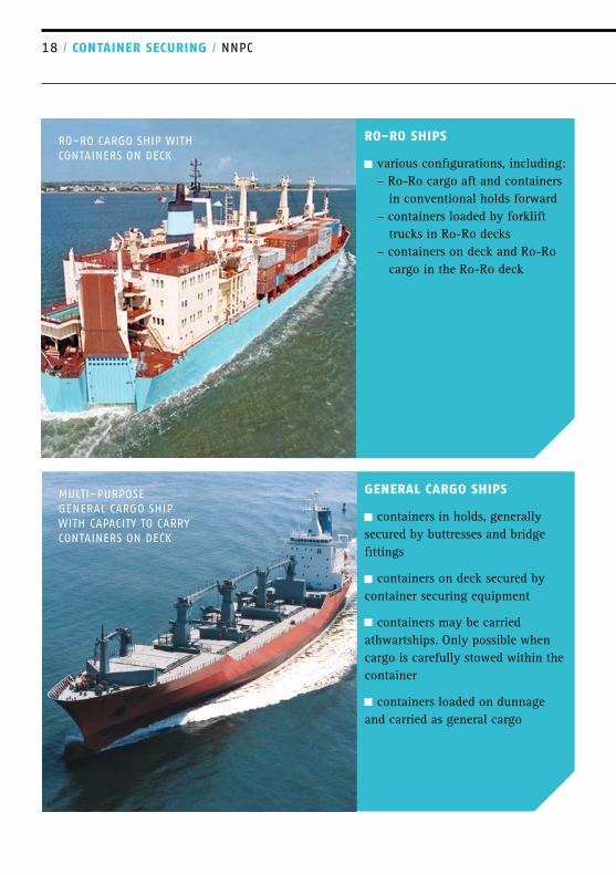
RO-RO ShIPS
various configurations, including: – Ro-Ro cargo aft and containers in conventional holds forward – containers loaded by forklift trucks in Ro-Ro decks – containers on deck and Ro-Ro cargo in the Ro-Ro deck
GENERAl CARGO ShIPS
containers in holds, generally secured by buttresses and bridge fittings
containers on deck secured by container securing equipment
containers may be carried athwartships. Only possible when cargo is carefully stowed within the container
containers loaded on dunnage and carried as general cargo
RO-RO CARGO ShIP wITh CONTAINERS ON DECk
MUlTI-PURPOSE GENERAl CARGO ShIP wITh CAPACITy TO CARRy CONTAINERS ON DECk

ShIPS / 19
ShIP ClASSIfICATION
The ship classification process ensures that the ship’s hull, hatch covers, lashing bridges, cell guides and fixed fittings have sufficient strength. Loose fittings such as container securing components may be excluded from this certification process. Although a classification society may assess the adequacy of loose fittings and assign a class notation, this examination is additional to the mandatory ship classification process.
P&l clubs require a ship to be approved for the carriage of containers by a classification society and for the container securing arrangements to at least meet that classification society’s design requirements.
Multi-purpose ships may carry containers and general cargo. These ships can be cellular container ships with a stiffened tanktop with the ability to ‘stopper’ (block) cell guides. Sometimes owners wish to carry bulk or general cargoes in container ships. A ship which is classed as a container ship will not have been assessed for this type of loading, nor will the inner bottom, hatch covers, loading manual, Cargo Securing Manual and ISM certification have been approved for the carriage of these cargoes. Before general cargo can safely be carried on a container ship certification as a general cargo ship is necessary. The club has published an edition of Standard Cargo on the subject of container ships and general cargo.
llOyD’S REGISTER’S ‘REGISTER OF ShIPS’ AND
‘RUlES & REGUlATIONS FOR ThE ClASSIFICATION
OF ShIPS’.

20 / CONTAINER SECURING / NNPC
foto
wim
te brake

CONTAINERS
Most containers carried at sea are designed and approved to ISO standard and are regularly inspected in accordance with the International Convention for Safe Containers (CSC) for damage, to ensure that they continue to be suitable for the very large loads which they are required to bear while at sea. There are various types, sizes and designs of container. Not all are suitable to be part of a container stow.
07
CONTAINERS / 21

22 / CONTAINER SECURING / NNPC
CONTAINER SIzES
Containers are standardised cargo units. They are normally manufactured to the sizes specified in ISO 668, but they can be manufactured in a variety of sizes and types, each designed to meet specific cargo and transportation requirements. Their length is usually 20 or 40 feet, although longer containers are used, principally in the US trade; these containers are 45, 48 and 53 feet long. Their width is standardised at 8 feet (2,438mm), although their height can vary. The term ‘high cube’ container usually refers to a standard sized container that has a height of 9 feet 6 inches. Container heights can be 8 feet, 8 feet 6 inches or 9 feet 6 inches.
Containers are referred to by the acronym TEUs – 20 foot equivalent units, or 40 foot equivalent units (FEUs).
The ISO standard for containers (ISO 668) defines dimensions, both internal and external, and load ratings. All containers have a framework and corner posts fitted with corner castings. The castings at each corner of the container support the container’s weight.
The castings are the only points at which a container should be supported and are used to attach securing fittings, such as lashing rods and twistlocks. The position and spacing of corner castings are carefully controlled.
Containers with stacking limitations (such as 5-high stack) have labels clearly marking these requirements. The stacking capability is also specified on the CSC Plate.
The usual value for allowable stacking is 192,000 kg, which is a 9-high stack of containers, calculated as 8 containers stacked above, each with a mass of 24,000kg (8x24,000=192,000).
Containers that are longer than 40 feet usually have additional support points at the 40-foot position so that they can be stowed over a standard 40-foot container. Standard sizes for ISO Series 1 freight containers include those shown in the table below.
Twenty-foot containers are actually a little shorter than 20 feet, so that two 20-foot containers can be stowed in a 40-foot bay. The actual dimensions are 12,192mm for a 40-foot container and 6,058mm for a 20-foot container. Thus, two 20-foot containers are 76mm shorter than a 40-foot container. This clearance is often referred to as the ‘ISO gap’.

CONTAINERS / 23
DO NOT lASh TO ThE OvERhANGING END OF A
45-FOOT CONTAINER
designation
(non-ISO)
1AAA
1AA
1A
1Ax
1bbb
1bb
1b
1bx
1CC
1C
1Cx
1D
1Dx
length
45’
40’
30’
20’
10’
width
8’
8’
8’
8’
8’
height
9’ 6”
8’ 6”
9’ 6”
8’ 6’’
8’
< 8’
9’ 6’’
8’ 6’’
8’
< 8’
8’ 6’
8’
< 8’
8’
< 8’
APPROxIMATE DIMENSIONS, IN FEET AND INChES. MOST COMMON SIzES hIGhlIGhTED. SUFFIx ‘x’ MEANS ThE CONTAINER hEIGhT IS lESS ThAN 8 FEET.
STANdARd SIzES fOR ISO SERIES 1 fREIGhT CONTAINERS

24 / CONTAINER SECURING / NNPC
CONTAINER TyPESThere are a number of types of container in common use. They all have basically the same frame, and the differences relate to what they can be used for and access. dRy vAN bOxES these are the most common type they have corrugated steel walls,
timber base, steel or glass reinforced plastic (GRP) top corrugated walls can be made from
plate from as little as 1.6mm (1/16 inch) in thickness their frame consists of side and end
rails, and corner pillars fitted with corner castings the closed end is approximately 4.5
times more stiff, in racking strength, than the door end closed doors are a component of their
strength
CURTAIN wAll CONTAINERS curtain wall containers are similar
to dry van boxes, but have fabric side walls that can be opened to facilitate easy cargo handling
REEFER UNIT
REfRIGERATEd CONTAINERS general construction as for dry van
boxes they usually have their own
refrigeration unit, with an air or water-cooled heat exchanger a small number of CONAIR boxes
use close-coupled ventilation they have their own data logger to
record temperature some have controlled atmosphere for
the carriage of fruit
40-FOOT DRy vAN bOx CONTAINER

TANk CONTAINERS
steel skeletal framework within which the tank is housed steel framework must have equiva-
lent strength to a dry van box the tank has its own design and
strength criteria and it may be a pres-sure vessel if carrying ‘dangerous goods’ the
tank container will also be certified to ADR/RID/IMDG
flAT-RACk CONTAINERS
the container frame can be folded flat for ease of transportation when empty the structure must have equivalent
strength to a dry van box
TwO FlAT RACkS OvER STOwED
EURO CONTAINERS
Euro containers are 45-foot containers designed to comply with EU Directive 96/53 they have shaped corner castings
to comply with road transportation regulations their cell guides need to be appro-
priately designed to ensure that the containers cannot slip out of them
CORNER CASTING ARRANGEMENT FOR A
EURO CONTAINER
TyPICAl ARRANGEMENT FOR A TANk CONTAINER
CONTAINERS / 25

26 / CONTAINER SECURING / NNPC
08 CONTAINER CONSTRUCTIONThe strength of a container is provided principally by the outer framework, side rails and corner posts, together with the corner castings. The side, end panels and closed doors provide racking strength.
CORNER POSTS
Effective stacking of containers relies on the strength of the corner posts to support the weight of the containers above. Damage to a corner post, in particular buckling, can seriously degrade its compressive strength and lead to the collapse of a container stack.A series of tests is undertaken on a prototype container to comply with the Lloyd’s Register Container Certification Scheme, the CSC and the applicable ISO standards.
These tests simulate the different loads the container is likely to be subjected to; an example of this in the photo above is a stacking test.
ThE OUTER fRAmE
Horizontal forces on the container, such as those caused by roll and pitch motions, are resisted by the racking strength of the container. This is
provided by the frame and alsoby the plate walls. Of course, soft-walled containers rely totally on the racking strength of the frame.
CORNER CASTINGS
A container’s corner castings take the twistlocks or stacking cones, which are used to connect containers to each other or to the ship’s deck/hold, and the lashing rods, which are used to secure and support the stow. During lifting, the crane’s spreader bar connects to the corner castings.
While compressive loads can be carried by the direct contact between the containers, tensile and shear loads are resisted by the loose fittings. It is important that the corner castings are in good condition if the fittings are to work effectively and perform theirintended function.
The position of corner fittings must be carefully controlled during the

manufacture of containers to ensure that they fit together properly and to ensure that the fittings work effectively.
fORklIfT POCkETS
These can be cut into the bottom side rail and are used when the containers are lifted by a forklift truck. Forklift pockets are a discontinuity in the side rail that could weaken the container if contact damage occurs.
CONTAINER CERTIfICATION
New designs of container are prototype tested to ensure that they have sufficient strength.
If tests prove satisfactory, then the container design may be certified by a classification society.
It is important to note that a container that has suffered damage to a corner casting or corner post will not be serviceable because: a damaged container may be unable
to bear the weight of those stowed above a damaged container may render
lashings ineffective lifting a damaged container is
hazardous
If one container in a stack fails, it is likely that the entire stack will collapse.
CONTAINER CONSTRUCTION / 27
CONTAINER TEST RIG

28 / CONTAINER SECURING / NNPC
CONTAINER CONSTRUCTION AND FAUlTS
CERTIfICATION
Certification is then issued by the classification society for containers of similar design, that are constructed by production methods and quality control procedures that are agreed andverified by survey. Changes in the method of construction may nullify the certification, unless the changes are approved by the classification society.
The Lloyd’s Register Container Certification Scheme (LR-CCS) covers three general categories of container:
ISO Series 1 containers – all types, including: dry van boxes, reefer
containers, open top containers, non-pressurised dry bulk containers and platform-based containers Tank containers Offshore containers
The scheme ensures that each contai-ner complies with the appropriate ISO standard and applicable regulations, covering for example: dimensions strength of walls, floor and roof strength of corner posts rigidity (longitudinal and transverse) weathertightness number of other features as
appropriate to the type of container, such as strength of forklift pockets

CONTAINER CONSTRUCTION / 29
A container that has satisfactorily passed the Lloyd’s Register Container Certification Scheme will bear the Lloyd’s Register logo.
When containers are strength tested, it is important to remember that they are not tested for vertical tandem lifting and that the corner posts are only tested for compressive strength. In addition, it is only the top corner fittings that are tested for lifting; the bottom fittings are never tested. Twistlocks may be approved for vertical tandem lifting; however, such lifting is dangerous and should only be contemplated when a container’s bottom corner castings are also approved for lifting. If in doubt, consult the ship’s P&I club.
ISO SERIES 1 – fREIGhT CONTAINERS
The primary documents for the design of ISO Series 1 Freight Containers are: ISO 668: Classification Dimensions
and Ratings
ISO 1161: Corner Fittings, Specification ISO 1496-1: Specification and
Testing. Part 1: General Cargo Containers for General Purposes ISO 1496-2: Specification and
Testing. Part 2: Thermal Containers ISO 1496-3: Specification and
Testing. Part 3: Tank Containers for Liquids, Gases and Pressurised Dry Bulk
INTERNATIONAl CONvENTION fOR SAfE CONTAINERS (CSC)
The CSC Convention sets out the standards for freight container construction and use.The convention contains regulations on construction, inspection, approval and certification.This includes design approval, witness of container manufacture and proto-type testing and issuance of a safety plate. The CSC approval or safety plate contains information on the contai-ner’s date of manufacture, the manu-facturer’s identification number, the gross operating weight, the allowable stacking weight and the transverse rac-king load. The plate may also have the end and/or side-wall strength value. The plate is issued when the container is manufactured.
In accordance with the CSC all con-tainers shall be examined at intervals specified in the convention by one of two ways: either by a ‘Periodic Exami-

30 / CONTAINER SECURING / NNPC
nation Scheme’ or under an ‘Approved Continuous Examination Programme’ (ACEP). Both procedures are intended to ensure that the containers are maintained to the required level of safety. The maximum period between examinations is set at 30 months or if there is a major repair or modificationand for the ACEP scheme for on hire/off hire interchanges. For tank contai-ners the ADR (Transport of Dangerous Goods by Road), RID (Transport of Dangerous Goods by Rail) and IMDG (Transport of Dangerous goods by Sea) also have in-service inspection requirements.The standard EN 12972 thoroughly details these requirements.
CERTIfICATION Of REEfER CONTAINERS
The ability of a reefer container to maintain a given temperature when using its integral refrigeration unit is tested in accordance with ISO 1496-2. This consists of two tests: one to determine the heat loss through the envelope of the container and the other to ensure the refrigeration unit can operate with a specific internal load. These tests are arranged during type approval. The amount of electrical power required to maintain a reefer container at a given temperature depends on the size of the container (TEU or FEU), the required cargo temperature, the cargo being carried and the external ambient air temperature.
For example, 9 kW of electrical power is needed to maintain a temperature of minus 18°C in a 40-foot container carrying frozen meat, while a container carrying fruit at 2°C requires approxi-mately 11 kW. This is because fruit respire and produce heat during transit.Certain cargoes, for example bananas, may require even more power because of the greater heat produced as they ripen. There is a high electrical load on the ship’s generators when reefer containers are carried.
CONTAINERS wITh OPEN dOORS
Some containers are certified for use with one or both doors open, or remo-ved. This may be necessary to ventilate cargo. A note saying the container’s doors can be open will appear on the CSC plate under the transverse racking entry. Unless a container is certified to have its doors open, the doors must be closed and secured – they are an integral part of a container’s strength.

lAShING COMPONENTSA variety of lashing components are available to secure containers, the majority of which are listed below. The table shows the locations where these components are commonly used.
09
fIxEd fITTING (ATTAChEd TO ShIP)
description Flush socket
Raised socket
lashing plate or ‘Pad-eye’
D ring
Dovetail foundation
Purpose locating base twistlocks or stacking cones in the cargo hold.
locating base twistlocks or stacking cones on deck.
Tie-down point for turnbuckle.
Alternative tie-down point for a turnbuckle.
base for sliding dovetail twistlock.
Image
Notes
Normally fitted over asmall recess to ensure watertightness. Clean and remove debris before use. Clean and remove debris before use.
Designed only for in- plane loading. An out-of- plane (out-of-line) load could bend the plate and may crack the connecting weld. Corrosion of the pin ends can weaken a D ring. Suitable for in-plane (in-line) and out-of-plane loading. Clean before use. keep well greased and examine regularly for damage or wear.
lAShING COmPONENTS / 31

32 / CONTAINER SECURING / NNPC
description Fixed stacking cone
Mid-bay guide
Purpose locating base twistlocks or stacking cones in the cargo hold.
To prevent transverse movement of 20-foot containers in 40-foot guides. Fitted at tanktop level.
Image
Notes
Often found at the base of a cell guide.
Does not interfere with general stowage of 40-footcontainers.
Loose fittings are those that are not permanently attached to the ship. Loose fittings must be certified by class or an appropriate recognised authority. However, they are not normally surveyed by the class society
surveyor during regular ship surveys. When using loose fittings, it is essential that the manufacturer’s instructions are followed at all times, especially when using fully automatic and semi-automatic twistlocks.
lOOSE fITTINGS IN COmmON USE
description lashing rod
Extension piece
Turn buckle (bottle screw)
Purpose To provide support for container stacks on deck.Used in conjunction with a turnbuckle.
To extend a lashing rod when securing ‘high cube’ containers. To connect a lashing rod to a lashing plate or D ring. Tightening puts tension into a lashing rod.
Image
Notes
Resists tensile loads. very long lashing rods can be difficult to handle and difficult to locate in a container corner casting. They can have eyes at each end. Fit at the base of al ashing rod and connect to the turnbuckle. Resists tensile loads and is used to keep the lashing tight. Regu-larly grease its threads. Ensure the locking nut or tab is locked.

description hanging stacker
Semi-automatict wistlock( SAT)
Twistlock
Stacking cone
Fully automatic twistlock (FAT)
Purpose Used in holds when 20-foot containers are carried in 40-foot guides. locks into corner casting above.
Placed between containers in a stack. locks into corner castings above and below.
Placed between containers in a stack. locks into corner castings above and below.
Placed between containers in a stack. Slots into corner castings.
Placed between containers in a stack. locks into container casting above; hooks into container casting below.
Image
Notes
Resists horizontal forces. likely to be put in place when container is on shore because of difficulty in fitting when on board. Resists horizontal and separation forces. Can be fittedonshore. Auto-matically locks into the lowercontainer when placed on top. It is easier to determine whether it is locked or not when compared to manual twistlocks. Unlocked manually. Resists horizontal and separation forces. Each fitting requires locking after fitting. left and right-hand types exist, causing uncertainty whether a fitting is locked or open. Resists horizontal forces. Many types exist. May be locked into bottom corner castings prior to lifting a container on board. A new and innovative design. Automatic unlocking during lifting. Usually opened by a vertical lift, with a twist/tilt. Should not be used if container corner castings are worn or damaged.
lAShING COmPONENTS / 33

34 / CONTAINER SECURING / NNPC
description Mid-lock
Purpose Placed between containers in a stack. locks into corner castings above and below. Used on deck between 20-foot containers in 40-foot bays, at mid-bay position.
Image
Notes
Resists horizontal and separation forces. Fitted to underside of container on shore and automatically locks into lower container when placed onboard. Con-sult the manufacturer’s instruction manual for information on the lock’s correct direction of fitting.
lOOSE fITTINGS IN lESS COmmON USE
These fittings are not commonly used but may be encountered occasionally. Fitting a bridge piece requires access
to the container top, something that should be avoided unless absolutely necessary.
description Sliding dovetail twistlock
bridge fitting
buttress
Purpose To connect bottom containers to the ship.
To link together the top containers of two adjacent stacks. Can be used on deck or in a hold. External support for container stacks in a hold.
Image
Notes
Fits into a dovetail foundation. Used on hatch covers and in holds where a raised socket could cause an obstruction. Resists tensile and compressive forces. Potential drop hazard for stevedores/crew during placement. Can resist compressive and tensile forces. Must be used in conjunction with higher-strength double stacking cones or link plates and aligned with side support structure.

description Double stacking cone
load equalising device
Penguin hook
Elongated socket
Purpose To link adjacent stacks, particularly those in line with buttresses.
To balance the load between two paired lashings.
Used as a supporting device in conjunction with a special lashing rod with an eye-end.
locating base twist-locks or stacking cones on deck.
Image
Notes
Resists horizontal forces. More commonly used on con-bulkers below deck.
Enables two parallel lashing rods to be connected to a single turnbuckle. Only use with designated lashing rods. likely to be put in place when container is on shore because of difficulty in fitting when on board. Risk of injury if it falls out when container is lifted onboard. Enables movement between a hatch cover and container to be taken up.
lAShING COmPONENTS / 35
ASSORTED TwISTlOCkS

36 / CONTAINER SECURING / NNPC
10 PRINCIPlES OF STOwAGEContainers are rectangular box-shaped units of cargo. It is easy to stow them in classical block stowage both on and below deck.
When containers are carried on deck, the ship is required to be approved for that purpose and the containers them-selves are secured with twistlocks and lashings. These usually consist of steel rods and turnbuckles.
When containers are carried below deck, the containers are slotted into cell guides on a cellular container ship, or sit on the tanktop, joined together with stacking cones, in the holds of a dry cargo ship. Containers can easily be stowed in box-shaped holds; it is more difficult to carry them in the holds of a dry cargo ship fitted with side hopper tanks, in which case, buttresses may be fitted.
When carried within a cell guide framework, no further external support is generally required. When 20-foot containers are stowed below deck in 40-foot cell guides, it may be beneficial to overstow the 20-foot containers with a 40-foot container. The Cargo Securing Manual should be consulted before loading.
Containers carried on deck may be secured by twistlocks alone, provided the stack is not more than two contai-ners high. When containers are carried three high, twistlocks alone may be sufficient depending on the weight of the containers.
Horizontal movement of a deck stow is resisted by the twistlocks or cones. Lifting of containers in extreme seas is prevented by the pull-out strength of the twistlocks. The limitation of a twistlockonly stow is often the racking strength of the containers. For stows of more than three containers high, lashing rods are fitted because they provide additional racking strength.
In the early days of containerisation, lashings were fitted vertically to resist tipping. However, it soon became clear that it is more effective to arrange the lashings diagonally, so that the container and the lashings work together to resist racking.
The usual arrangement is to fit one tier of lashings, placed diagonally within

the width of the container, with the tops of the lashing rods placed in the bottom corner castings of the secondtier containers. This is called ‘cross-lashing’. An alternative arrange-ment, with the lashing rods located outside of the width of the container, is called ‘external lashing’. This is often used for high stacks which are lashed from a two-tier lashing bridge.
To enable the fitting of twistlocks, a twistlock is designed with a vertical and horizontal gap between it and a container’s corner casting. This becomes important when considering how lashings behave during ship roll, pitch and heave. Lashing rods are always fitted tight and kept tight by adjusting the turnbuckle. When force is trans-mitted to securing equipment during
ship rolling, it is the lashing rods that bear the force first. It is only after the stack of containers has deflected and the gap at the twistlock has been ‘taken up’ that twistlocks become tight. For this reason, it is important to only use lashing rods that are in good condition and to apply them correctly.A second set of lashings may be fitted, connected to the bottom of the third tier of containers, as shown in the diagram.
If additional lashing strength is required, parallel lashings (para-lashings) may be used.With this arrangement, lashings are arranged in parallel, one fitted to the top of the first tier and one to the bottom of the second tier. Tests have revealed that many containers are not
SECURING wITh PARAllEl lAShING
RODS AND SEMI-AUTOMATIC TwISTlOCk
PRINCIPlES Of STOwAGE / 37

38 / CONTAINER SECURING / NNPC
able to bear large downward loads on the upper castings, as can occur with para-lashings. This is particularly the case at the door end where the upper casting frequently overhangs the door and consequently has little support. The effectiveness of parallel lashings is taken as the lesser of 1.5 times that of a single lashing or the strength of the corner casting.
For ease of loading and discharge, bridge fittings that link adjacent stacks of containers together are not commonly fitted. However, since the force distribution and the response of adjacent container stacks will be similar, there is, in general, negligible load transfer between the stacks when linked together.
Bridge fittings tend to be used only on isolated adjacent stacks of containers in the holds of a dry cargo ship.
The ship’s approved Cargo Securing Manual contains information on how to stow and secure containers, and on any strength or stack weight limitations.
The most common mistakes made are to exceed the permissible stack weight, to incorrectly apply lashings and to place heavy containers near the top of a stow.
CONTAINERS CARRIEd bElOw dECk IN CEll GUIdES
The cargo holds of most container ships are designed for the carriage of 40-foot containers, with the containers held in place by cell guides. The cell guides are generally steel angle bars orientated vertically, with entry guides at the top to assist with locating the container – the clearances, and hence construction tolerances, are very tight.
The cell guides provide adequate longitudinal and transverse support to the 40-foot containers and no further securing arrangements are necessary. The lowest container in each stack sits on a pad, which is supported by the stiffened structure below the tanktop.
Twenty-foot containers may be stowed in 40-foot bays. This arrangement, referred to as mixed stow, requires longitudinal and transverse support for the containers where they meet at the mid-length position. This is achieved by mid-bay guides at the tanktop, placing hanging stackers between tiers of containers and possibly oversto-wing two 20-foot containers with one or more 40-foot containers. Isolated stacks should be avoided.In general, four hanging stackers should be fitted below each container, unless the Cargo Securing Manual specifically permits a lesser number.
Before loading containers in cell gui-des, it is important to make sure that the guides are not bent or deformed.

PRINCIPlES Of STOwAGE / 39
40-FOOT CONTAINERS IN 40-FOOT CEll GUIDES
20-FOOT CONTAINERS IN 40-FOOT CEll GUIDES
20-FOOT CONTAINERS IN 40-FOOT CEll GUIDES wITh 40-FOOT CONTAINERS STOwED AbOvE
TyPICAl ARRANGEmENTS fOR CONTAINERS STOwEd bElOw dECk

40 / CONTAINER SECURING / NNPC
CONTAINERS CARRIEd bElOw dECk wIThOUT CEll GUIdES
Containers are generally stowed in the fore and aft direction, with the containers secured using locking devices only or by a combination of locking devices, buttresses, shores or lashings. The aim is to restrain the containers at their corners. Twistlocks are very good at preventing corner separation.
When carrying containers in the hold of a bulk carrier or general cargo ship, base containers are secured with twistlocks or cones. Buttresses should be fitted to provide lateral support. A platform, with sockets for cones or twistlocks, may be fitted in the forward and aft holds. This forms the basis for block stowage of containers when combined with cones, twistlocks and bridge fittings.
Various designs of portable buttress are available.
Aim for a tight block when loading containers below deck on a con-bulker. During loading, check to make sure that means are applied to ensure that the lowest tier does not slide when the ship rolls.
CONTAINERS CARRIEd ON dECk
Containers are usually stowed longitudinally in vertical stacks.
Containers within each stack are fastened together with twistlocks. The bottom corners of each base container are locked to the deck, hatch cover or pedestal with a twistlock. When stacked in multiple tiers, the containers are usually lashed to the ship’s structure by diagonal lashing rods.
The lashing rods are usually applied to the bottom corners of second or thirdtier containers. On ships fitted with lashing bridges, the lashing rods may be applied to the bottom corners of fourth or fifth-tier containers.
Lashings are applied so that each con-tainer stack is secured independently. In theory, the loss of one stack should not affect its neighbours.
Transverse stowage, although possible, is uncommon, mainly because cargo could move or fall out of the container when the ship rolls, but also because
TyPICAl bUlk CARRIER STOwAGE ARRANGEMENT
wITh bUTTRESSES, USING SINGlE/DOUblE
STACkING CONES AND bRIDGE FITTINGS

PRINCIPlES Of STOwAGE / 41
transverse stowage requires rotation of the spreader bar of the shore gantry crane.
In some cases, containers are carried on deck in cell guides, in which case, the principles on page 33 apply. The same principles also apply to hatch-coverless container ships.
Containers carried at the sides of the ship are subject to wind loading. Consequently, it is common for ‘wind lashings’ to be fitted. These may be vertical or diagonal. It may also be necessary to fit wind lashings inboard if there are vacant stacks.
CONTAINERS SECURED by TwISTlOCkS. USUAlly FOR TwO TIERS ONly
CONTAINERS SECURED by TwISTlOCkS AND lAShING RODS. lAShING RODS
TO bOTTOM OF SECOND TIER. wIND lAShINGS TO bOTTOM OF ThIRD TIER
TyPICAl ARRANGEmENTS fOR CONTAINERS STOwEd ON dECk

42 / CONTAINER SECURING / NNPC
CONTAINERS SECURED by TwISTlOCkS AND lAShING RODS. lAShING
RODS TO bOTTOM OF ThIRD TIER
CONTAINERS SECURED by TwISTlOCkS AND lAShING RODS,
‘ExTERNAl lAShING’ ARRANGEMENT
AS AbOvE bUT lAShINGS ORIGINATE FROM A lAShING bRIDGE.
lAShING RODS TO bOTTOM OF FIFTh TIER
Typical stowageexternal lashings with
parallel lashings
Typical stowageexternal lashings
without parallel lashings

PRINCIPlES Of STOwAGE / 43
whEN STOwING ANd SECURING CONTAINERS, ThE fOllOwING POINTS ShOUld bE bORNE IN mINd:
a deck stack of containers is only as strong as the weakest component in that stack. Premature failure of a component can cause loss of an entire stack. During loading, containers should be inspected for damage and, if damaged, they should be rejected
twistlocks limit vertical and trans-verse movement. Diagonal crossed lashing rods, placed at the ends of a container, can withstand large tensile loads
outside lashings are sometimes used. These are lashings that lead away from a container. However, although this arrangement provides a more rigid stow than a combination of crossed lashings and twistlocks, it is less common
containers exposed to wind loading need additional or stronger lashings. When carried in block stowage, it is the outer stacks that are exposed to wind loading. However, when carried on a partially loaded deck, isolated stacks and inboard containers can also be exposed to wind, in which case, additional lashings need to be applied
if containers of non-standard length, that is, 45, 48 or 53 feet are carried, the ship arrangement will need to be specially adapted
45-foot containers fitted with additional corner posts at 40-foot spacing can be stowed on top of 40-foot containers. Lashings can be applied in the normal way. It should be noted, however, that the additional corner posts may not be suitable for carrying the required loads, either from the container itself or from those stowed above. Lashings should not be applied to the overhang. The container specification and the Cargo Securing Manual should be consulted
40-foot containers may be stowed on top of 45-foot containers. However, this arrangement of stowage will present difficulties in fastening/ unfastening twistlocks, and it will not be possible to apply lashings to the 40-foot containers when carrying over-width contai-
ners, for example 45-foot or 53-foot containers with width 8’-6”, adaptor platforms may be used. These must be certified by a class society or an appropriate recognised body. The arrangement must be defined and approved in the ship’s Cargo Securing Manual
twistlocks should always be locked, even when the ship is at anchor, except during container loading and unloading. Lashing rods should be kept taut and, where possible, have even tension. Lashing rods should never be loose nor should they be overtigh-tened. Turnbuckle locking nuts should be fully tightened

44 / CONTAINER SECURING / NNPC
as a ship rolls, pitches and heaves in a seaway, tension, compression and racking forces are transmitted through the container frames, lashings and twistlocks to the ship’s structure. However, clearances between securing components and the elasticity of the container frame and lashing equipment produce a securing system that forms a flexible structure. Thus, a deck stow of containers will move
containers can be held by only twistlocks when two or three tiers are carried on deck, depending upon container weights arrangements with automatic and
semi-automatic twistlocks are used to reduce time spent securing the stow and to eliminate the need for lashers to climb the stacks ChECkS ANd TESTS dURING dISChARGE ANd lOAdING
regularly examine lashing components, looking for wear and tear, damage or distortion. Check that left-hand and right-hand locking twistlocks are not being mixed in the same storage bin. Remove from the ship any lashing component found to be worn, damaged or distorted
make arrangements for some damaged or distorted lashing components to be sent for non- destructive testing. This will determine their strength and help to establishreplacement criteria
carefully check twistlocks that stevedores return to the ship as the locks might not originate from your ship, that is, their strength and locking direction could differ
discourage stevedores from treating lashing equipment roughly as this can induce weakness
examine dovetail foundations, D rings and pad-eyes for damage. Repair if damage is found
observe the loading of containers to determine if stowage is in accordance with the stowage plan and that best practice is always followed
observe the application of lashings to make sure that they are correctly applied in accordance with the require-ments set out in the Cargo Securing Manual

ChECkS ANd TESTS AT SEA
24 hours after sailing, examine, check and tighten turnbuckles. Check that lashings are applied in accordance with the Cargo Securing Manual and that twistlocks have been locked
examine lashings daily. Check that they have not become loose and tighten turnbuckles as necessary
before the onset of bad weather, examine lashings thoroughly and tigh-ten turnbuckles, being careful to keep an equal tension in individual lashing rods. If necessary, apply additional lashing rods to the outboard stacks and to stacks with 20-foot containers in40-foot bays
re-check lashings after passing through bad weather
make sure that lashing equipment that is not in use is correctly stored in baskets or racks
make an inventory of lashing equipment and order spares before they are needed
check that refrigerated boxes remain connected to the ship’s power supply
PRINCIPlES Of STOwAGE / 45
TRANSPORT OF 40-FOOT CONTAINERS

46 / CONTAINER SECURING / NNPC
11 ShIP’S bEhAvIOUR Container ships, due to the nature of their trade, are required to keep to very tight operating schedules. Maintaining the schedule is an important part of the liner trade. As a result, these ships have powerful engines, not only to provide the high speeds required, but also to enable speed to be maintained during bad weather.
The consequence is that, at times, container ships can be driven hard. When ships are driven hard in bad weather, the loads on the lashings can be severe.
There are many load components arising from a ship’s motion. These are discussed below.
ShIPS’ STRUCTURE
The combined weight of a stack of containers may amount to a total downward force on the tanktop, through each container corner casting, of up to 100 tonnes. When four contai-ner corners are placed close together, such as at the mid-hold position when carrying 20-foot containers, the total local load on the tanktop may be four times this load.
During classification, the strength of the ship’s structure to support containers is verified and approved. This includes assessment of the
strength of the tanktop, the cell guides and, on deck, the strength of the hatch covers, lashing bridges, pedestals and the fixed fittings associated with the container stow.
It is important to carry containers within the loading conditions imposed by the classification society. Container loads should never exceed the limits set down in the ship’s loading manual.
CONTAINER STRENGTh ANd ShIP mOTION
Although a ship has six degrees of motion, it is roll, pitch and heave which produce the most significant contributions to the forces on a contai-ner stow. Surge is important for road and rail transportation and containers are designed with this in mind.
The motion of a ship in irregular seas is itself irregular and is impossible to accurately predict. Consequently, when calculating accelerations on a stack

of containers, regular cyclic response is assumed in association with an assumed maximum amplitude. Empirical formulae for maximum amplitude and period of response are defined in the Rules and Regulations for the Classification of Ships by Lloyd’s Register. Rolling motion is dominant in the calculation of forces, but rolling must be considered in association with the other components of the ship’s motion to establish the largest likely combination of forces which the stow may experience.
For calculation purposes, the forces acting on a container may be resolved into components acting both parallel to, and perpendicular to, the vertical axis of the container stack. Gravity acts vertically downwards and, therefore, when the stack is inclined at maximum roll or pitch, there are force components of static weight acting both parallel to, and with, the vertical axis of the stack. The dynamic components of force are vectors. These are combined algebraically with the static components.
Wind is assumed to act athwartships and to affect only the exposed stacks on the windward side of the ship. The magnitude of wind force, for a wind speed of 78 knots, is about 2 tonnes on the side of a 20-foot container and about 4 tonnes on a 40-foot. The vertical component of wind on the top of the uppermost inclined container is ignored.
The assessment of the effect of green seas on exposed container stacks is by necessity empirical. The general princi-ple is to require the container securing arrangement in the forward quarter of the ship to be suitable for forces increased by 20%, except when the ship has an effective breakwater or similar.
Calculations of forces acting on a container consider various combina-tions of the individual components of motion. Within each combination it is necessary to define the instantaneous positions in the cycle of motion at which the calculations are made.
Of course, in an actual seaway, all components of motion act simultane-ously to a greater or lesser extent.
llOyd’S REGISTER RUlES AllOwAblE fORCES ON AN ISO CONTAINER (ISO 1496-1:1990) The calculation of the forces in the lashing arrangements is clearly a very complex matter.This is further exacerbated by the de-flections of the hull. For example:
the cross-deck structure may move by as much as 50mm as the containers surge forward and aft
as the ship makes its way through a head or stern quartering sea, the hull twists, distorting the hatch openings
ShIP’S bEhAvIOUR / 47

48 / CONTAINER SECURING / NNPC
PARAmETRIC ROllING
The term parametric roll is used to describe the phenomenon of large, unstable rolling which can suddenly occur in head or stern quartering seas. Due to its violent nature and the very large accelerations associated with the onset of parametric rolling, there is widespread concern for the safety of container ships. Possible consequences include loss of containers, machinery failure, structural damage and even capsize.
Parametric roll is a threshold pheno-menon. This means that a combination of environmental, operational and design parameters need to exist before it is encountered.
These are: ship sailing with a small heading an-
gle to the predominant wave direction (head or stern quartering sea)
wavelength of the predominant swell is comparable to the ship’s length wave height is fairly large
ship’s roll-damping characteristic is low
If resonance occurs between the wave encounter period and the natural, or twice natural, roll period of the ship, then parametric roll motion can be experienced.
why ARE lARGE CONTAINER ShIPS vUlNERAblE?
Fine hull forms with pronounced bow flare and flat transom stern are most vulnerable to parametric roll.Such features contribute to the varia-tion of the ship’s stability characteris-tics due to the constant change of the underwater hull geometry as waves travel past the ship.
CAlCUlATION OF FORCES

Although this phenomenon has been studied in the past, it has only come to prominence with the introduction of the larger container ships. Until the 1990s, it was considered critical only for ships with marginal stability and fine-lined warships.
CONSEqUENCES Of A PARAmETRIC ROll
A parametric roll can have dire consequences for container securing and for operation of machinery.
It is an extreme condition for contai-ner securing since it combines the effect of large roll and pitch amplitu-des. This scenario imposes significant loads on container securing systems.
In theory, the container securing system could be designed to withstand such extreme motions. The consequen-ce would be a significant reduction in the number of containers that could be carried on deck. So, essentially, there is a balance between increased container security and the limitations imposed by securing requirements.
The extreme roll angles reached during a parametric roll usually exceed those adopted during machinery design. Indeed, it would be very difficult to bench test a large marine diesel engine at 40 degree angles. Possible conse-quences on machinery operation of the ship heeling to these very large angles include loss of cooling water suction, exposure of lubricating oil sumps and,
for resiliently mounted engines, problems with the connection of services – and hence shutdown of the main engine.
The following points should be borne in mind:
parametric roll is a relatively rare phenomenon occurring in head or following seas, which is characterised by rapidly developed, large, unstable ship rolling
risk control options exist in both design and operation of container ships that can effectively reduce the likelihood of a parametric roll occurring. Reducing the likelihood of its occurrence is considered a more effective approach than mitigating the consequences
compliance with Lloyd’s Register’s current requirements for container securing systems can reduce the risk of container losses
masters should be aware that when conditions for parametric rolling exist, ie. head/stern seas with wave length similar to the ship’s length, the action of putting the ship’s head to the sea and reducing speed could make rolling worse. Other action to ease the ship’smotion will be necessary, depending upon the prevailing weather
the North Pacific in winter is especially prone to these conditions
ShIP’S bEhAvIOUR / 49

50 / CONTAINER SECURING / NNPC
OUTbOARD CONTAINER DAMAGED by hEAvy SEA

CONSEqUENCES OF FAIlURE
CASE STUDyThe consequence of failure is almost always loss or damage of containers. The club has been involved in every type of incident following container loss, from widespread pollution after a floating container hit a ship’s hull and pierced a fuel tank, to wreck removal when sunken containers contained toxic chemicals, to a seaman hit by cargo falling from an open container. The study which follows graphically illustrates how simple faults, on a well run ship, can give rise to large container losses and the incidents described above.
12
CONSEqUENCES Of fAIlURE / 51

52 / CONTAINER SECURING / NNPC
It was February and the Panamax container ship had loaded in Northern hemisphere ports for China. She had seven holds and could carry over 3,000 containers, although less had been loaded on this occasion. Loading was homogeneous, without isolated stacks, but heights of containers differed. Containers were loaded on deck, five high in some bays and three high in others. Lashings consisted of base (manual) twistlocks fitted into dovetail foundations with semi-automatic twistlocks used between containers. Parallel crosslashings were applied using short and long lashing rods with turnbuckles. These connected to the top corner of first tier containers and to the bottom corner of second tier containers. Wind lashings were applied on the outboard stacks with long rods connected to the bottom corner of
third tier containers. The ship’s GM was 2.0m.
The schedule required sailing south along the western seaboard of the Uni-ted States before crossing the Pacific to Japan and China. The ship was on a southerly course when she encountered strong head winds with heavy head seas and swell. She was pitching and rolling heavily with occasional rolls to very large angles when a loud crash was heard. It was suspected that containers had been lost or had shifted. Next morning the extent of damage could be seen; the entire stack forward of the bridge had collapsed. Many containers remained on board but some had fallen overboard. Investigations revealed that a numberof classic mistakes had contributed to the loss.
COllAPSED CONTAINER – CRUSh DAMAGE

CONSEqUENCES Of fAIlURE / 53
COURSE ANd SPEEd
The ship was proceeding on a southerly course into head seas and was pitching and rolling heavily. Rolling in head seas may be associated with the phenomenon known as ‘parametric rolling’ which occurs because the ship’s waterplane area changes as waves pass along the ship’s length. Maximum rolling can occur when a wave’s length is comparable to the ship’s length. At the instant when the ship’s midship is supported by a wave crest, with the bow and stern in a wave trough, there is an instantaneous loss of waterplane, sudden and massive loss of righting force and the ship may roll to very large angles. As the wave passes along the ship’s length the situation is reversed, strong righting forces are exerted and the ship rights herself but only to roll again as the next wave passes. Effectively, the ship performs simple harmonic motion but with violent rolling.
During the conditions of very severe rolling, containers stowed on deck can be subjected to massive separation forces, forces that are likely to exceed the combined strength of the securing system. Parametric rolling may be prevented by alteration of course or change of speed.
STOwAGE ANd SECURING
The bottom container in each stack was secured by twistlocks fitted to dovetail sockets which slide into dovetail foundations. Dovetail founda-tions, for a variety of reasons, have a tendency to wear which can result in movement of the securing twistlock. In extreme circumstances the base twistlock can be pulled out of the dovetail foundation leaving only the lashing rods to hold containers in place, something which they are not designed to do. This had happened and as a consequence turnbuckles had pulled apart and lashing rods had broken.
One end of the lashing rod was connected to a D ring and D rings were welded to the lashing bridge for this purpose. Some of the D rings had been pulled apart and it was found that D ring securing collars had been poorly welded and were weak. Quality of welding is a matter for new build superintendents, not the ship’s crew but during routine maintenance, chipping and painting, welds which connect securing points to the ship should be examined for corrosion,
lAShING FAIlURE CAUSING CONTAINER lOSS

54 / CONTAINER SECURING / NNPC
damage or defect with any observed deficiency being reported to the master. On this ship D ring collar welds had very poor penetration and the securing point was weak.
This is not something a ship’s crew can correct but an observant seaman who spots a defect and reports it can be instrumental in preventing a major loss. Base foundations need regular examination and test, something which should form part of the ship’s planned maintenance procedure.
Not all base twistlocks had failed, some were found unlocked and it was suspected that the ship had been using left-hand and right-hand locks in the same stow. Using left-hand and right-hand locks in the same stow makes it very difficult to detect whether a twistlock is actually locked or open. Ship’s crew should be checking for incorrectly handed locks and removing them.
The ship had been loaded in accor-dance with the limits imposed by class and nothing improper was found with container distribution or stack weights. However, mathematical simulation of the forces imposed on the containers during violent rolling indicated that racking and compression forces on the containers exceeded the design strength of lashings by 1.5 and 2.5 times respectively. This would have resulted in very large separation forces on the stacked containers. Prior to the incident the crew had checked that turnbuckles were evenly tightened but they had not applied additional wind lashings. Any additional lashings applied in exposed locations before the onset of severe roll and pitch conditions should improve combined lashing strength, provided the lashings are applied to the bottoms or tops of containers which are only secured by twistlocks.
With the benefit of hindsight it is seen how simple errors can cause container loss. The weather conditions experien-ced were not extreme but the effects of parametric rolling, worn base foundations and weak ‘D’ ring collars all contributed to the catastrophic loss of containers. It is rarely a single failure that results in a loss but a sequence of events. For this reason it is essential to follow best practice and the principles set out in this guide.
FAIlED TwISTlOCk

foto
wim
te
brak
e

A MASTER’S GUIDE TO:
AuthorsEric Murdoch, Chief Surveyor Standard P&I ClubDavid Tozer, Business Manager Container Ships Lloyd’s Register
Photo coverWim te Brake, Amsterdam
Design In Ontwerp, Assen
NNPCRijksstraatweg 3619752 CH Haren (Gr.)