Embed Size (px)
Citation preview

International Journal of Solids and Structures 46 (2009) 4054–4063
Contents lists available at ScienceDirect
International Journal of Solids and Structures
journal homepage: www.elsevier .com/locate / i jsolst r
A macroscopic-level hybrid lattice particle modeling of mode-I crack propagationin inelastic materials with varying ductility
G. Wang a,*, A. Al-Ostaz a, A.H.-D. Cheng a, P.R. Mantena b
a Department of Civil Engineering, University of Mississippi, Oxford, MS 38677-1848, USAb Department of Mechanical Engineering, University of Mississippi, Oxford, MS 38677-1848, USA
a r t i c l e i n f o
Article history:Received 5 January 2009Received in revised form 22 June 2009Available online 6 August 2009
Keywords:Fracture mechanicsCracksLattice modelParticle modelHybrid lattice particle modelConstitutive relations
0020-7683/$ - see front matter � 2009 Elsevier Ltd. Adoi:10.1016/j.ijsolstr.2009.08.001
* Corresponding author. Tel.: +1 662 915 5369; faxE-mail address: [email protected] (G. Wang).
a b s t r a c t
This paper presents a numerical method, known as hybrid lattice particle modeling (HLPM), for the studyof mode-I crack formation and propagation in two-dimensional geometry subject to a fixed-grip condi-tion. The HLPM combines the strength of two numerical techniques, particle model (PM) and latticemodel (LM), for the purpose of solving dynamic fragmentation of solids within a various Poisson’s ratiorange. A Lennard-Jones-type potential is employed to describe the nonlinear dynamic interaction of eachmacroscopic-size particle with its nearest-neighbors. Crack initiation and propagation is investigated formaterials with different Young’s modulus, tensile strength and varying ductility. It is demonstrated thatcrack patterns and propagation closely match the anticipated physical behavior of inelastic materials.Finally, the HLPM is applied to the investigation of a functionally designed composite material of an elas-tic–brittle infrastructure material coated with a ductile layer for the protection of fracture propagation.The ultimate application is aimed at the retrofitting of failing infrastructure.
� 2009 Elsevier Ltd. All rights reserved.
1. Introduction
Dynamic fracture is a complex and multi-scale physical phe-nomenon. From the microscopic point of view, fracturing is a pro-cess that material becomes separated due to the successivebreakage of atomic bonds. Since the intrinsic strength propertiesat atomic structure level are available, molecular dynamics (MD)analysis has been the primary tool at the nano scale. Moreover, adiscrete microscopic description in MD also allows defining localtemperatures, potential energies, stress distributions and otherquantities. These parameters present a precise physical meaningand are the key to understanding fracture. Thus, MD can providea more fundamental insight into material behavior and its interac-tions. However, although MD simulation has benefitted from therapid development of computing power and is becoming increas-ingly popular, the present state of computer technology is stillfar from being able to meet the demands of the macroscopic tasks.For example, we currently still cannot simulate a 1� 1� 1 cm3 cu-bic copper body at atomic level because the body consists of 1024
copper atoms, a number so large that no computer in the worldcan handle it. The second difficulty is its incapability in reachingthe practical time scales. For instance, the laboratory dynamic frac-ture experiments generally last in microseconds (1 ms = 10�6 s),while the MD model time steps are typically in the nano (10�9)
ll rights reserved.
: +1 662 915 5523.
or pico (10�12) second range. As such, the MD is limited to a narrowrange of solving nano- to micrometer scale problems. For this rea-son, a numerical tool for the modeling of dynamic fracture at mac-roscopic level is needed.
To successfully solve the dynamic fracture of materials at mac-roscopic level, it is critical if the model can deal with the uncertainevaluation of material body – large deformation or even fragmen-tation at a very high rate. In the other word, a successful dynamicfracture solver lies in an efficient solution of ‘‘re-meshing” in com-putation. The current numerical approaches for dynamic fracturesimulation at macroscopic level can be generally classified intotwo categories – a continuum mechanics based approach (CMBAfor short) and a discrete element based approach (DEBA for short).In brief, the CMBA is built up regarding the material body as onecontinuum media. Numerically, such models, e.g., finite elementmethod (FEM), use space-averaging to set up constitutive equa-tions within each element. In contrast, the DEBA shares a commonconcept of ‘‘discrete material”, and the constitutive equations areassigned to define the interaction among the discrete neighbors.Examining the state-of-the-art of the research, we conclude thatFEM, the most widely used CMBA, has difficulty in solving dynamicfracture problems, particularly in simulating collapse/fragmenta-tion of materials under extreme loadings. Although FEM has con-stantly been developed to meet such requirements and severalre-meshing techniques, i.e., Lagrange, Euler and Arbitrary LagrangeEuler, have been well established, fragmentation of materials isstill unable to be well simulated. In contrast, the discrete element
G. Wang et al. / International Journal of Solids and Structures 46 (2009) 4054–4063 4055
based, or meshless, approach is robust in solving the re-meshing.Fig. 1 illustrates a material impact simulation by using FEMaccounting for different re-meshing skills and by a meshless mod-el, smoothed particle hydrodynamics (SPH) (Quan et al., 2003). It isclearly shown that the DEBA is superior to the CMBA in solving thefragmentation of materials; hence, it attracts increasing interests.
Particle modeling (PM) is the one among a number of thebranches of DEBAs (Cundall, 1988; Meguro and Tagel-Din, 2000;Oñate et al., 2004; Monaghan, 2005). The PM was originally pro-posed by Greenspan (1997). In essence, PM, treating each compu-tation cell as a particle with the mass lumped to its center, can beregarded as an upscale MD, but applied to large length scale andtime scale problems. However, Greenspan (1997) developed suchmodel with in mind more fluid modeling than solid modeling. Asa consequence, there was no direct linkage to the solid materialproperties, making PM an empirical model without demonstratedvalidation with real engineering problems.
Lattice model (LM), on the other hand, has a long history of suc-cess in modeling micromechanics solid problems (Askar, 1985;Noor, 1988; Ostoja-Starzewski, 2002, 2007; Bolander and Suku-mar, 2005; Berton and Bolander, 2006). The LM, however, doesnot have the flexibility of particle models, in which the particlescan be subjected to very large deformation (displacement) andeven fragmentation. Such limitation of LM comes from a fact ofthat it adopts a conjugate gradient method with respect to mini-mizing the total potential energy stored in all spring bonds todetermine the displacement. Consequently, only one bond is al-lowed to fracture during each computational cycle (Alkhatebet al., 2009). Hence, the LM has so far been restricted to small mo-tions. It is basically a static/quasi-static model, and does not modelthe dynamic fracture process. In Table 1, the strengths and weak-
Table 1Comparison of the lattice model (LM), the particle model (PM), and the hybrid lattice par
Lattice model (LM) Particle model (PM)
Particle interaction Spring (axial/angular), beam, etc. Lennard-Jones poten
Interactionneighborhood
Not limited to nearest neighbor Nearest neighbor on
Mesh system Small deformation Large deformationPoisson’s ratio Flexible FixedTime process Static Dynamic based on NForce–displacement
relationDisplacement (strain) interpreted fromforce (stress)
Force interpreted frbetween particles)
Fig. 1. A material impact simulation by using FEM accounting for different re-meshinghydrodynamics (SPH) (Quan et al., 2003).
nesses of the traditional LM and PM are summarized andcompared.
To extend the capability of both LM and PM, and to allow themodeling of dynamic fracture and fragmentation of materialscaused by impact, blasting and other extreme loadings, a hybridlattice particle model (HLPM) has been developed based on Wangand Ostoja-Starzewski’s PM (2005). As demonstrated in Table 1,the HLPM has been proposed that combines the strengths of LMand PM (Wang et al., 2009), in which the interaction potentialcan be described by employing either linear (quadratic) or nonlin-ear (Lennard-Jones or polynomial) type to the axial/angular link-age. The defined spring constants are then mapped into latticesystem, which are in turn matched with the material’s contin-uum-level elastic moduli and strength. The HLPM can readily sim-ulate dynamic behaviors of materials at macro-scales with avarying Poisson’s ratio range (Wang et al., 2009). The principle ofHLPM can be described as follows: the particle–particle interactionis derived from lattice modeling (LM) theory whereas the compu-tational scheme follows particle modeling (PM) technique. Oncethe translational strength is exceeded, the spring is broken and afracture is created.
The advantages of HLPM over the existing discrete elementbased methods can be summarized as follows:
(1) Easy for the determination of input parameters. Four conser-vative/equivalent rules (mass, potential energy, Young’smodulus and tensile/compression strength) are required todetermine the material properties for the input datasheet.
(2) Easy for implementation. Since the physical size of each par-ticle is ignored other than its equivalent mass, the algorithmof coding a HLPM computation is fairly easy.
ticle model (HLPM).
Hybrid lattice particle model (HLPM)
tial (axial only) Spring (axial/angular) mimicking the Lennard-Jones potential
ly Not limited to nearest neighbor
Large deformationFlexible
ewton’s second law Dynamic based on Newton’s second lawom displacement (distance Force interpreted from displacement (distance
between particles)
skills, Lagrange, Euler and Arbitrary Lagrange Euler (ALE), and smoothed particle

4056 G. Wang et al. / International Journal of Solids and Structures 46 (2009) 4054–4063
A successful HLPM simulation have been achieved in predictingthe fracture pattern of an epoxy plate with randomly distributedholes in tension, shown in Fig. 2(a) and (b) (Ostoja-Starzewskiand Wang, 2006). Here is pointed out that, in the simulation, thePoisson’s ratio of epoxy was set to 1/3. This is a special case ofHLPM in which all the angular interactions are absent (Wanget al., 2009). As the figure illustrates, compared with the experi-mental observation, HLPM prediction of crack pattern seems moreaccurate than that of the FEM solution. Moreover, two successfulqualitative comparisons currently have been completed with thedynamic failure experiments of polymeric material (nylon-6,6and vinyl ester) indentation, shown in Fig. 3(a) and (b) (Wanget al., 2008a) and Fig. 4(a) and (b) (Wang, 2009), respectively.
After gaining the confidence of HLPM from the above-men-tioned fracture study cases, in this paper, we step forward to inves-
Fig. 2. Experimental and modeling results of epoxy in tension: (a) experiment (Al-Ostaz and Jasiuk, 1997) and (b) HLPM simulation (Ostoja-Starzewski and Wang,2006).
tigate the modeling capability of the HLPM on the initiation andpropagation of mode-I fracture in inelastic materials with differentductility employing a fixed-grip condition. As the mechanism forfracture formation and propagation in the lattice and the particlemodel is very different from that of the continuum mechanicsbased fracture mechanics model, it is not clear that the physicalphenomenon of stable and unstable fracture growth can be cor-rectly predicted. In short, the continuum model uses the stressintensity factor and energy release rate concepts for fracture crea-tion and propagation; while the discrete HLPM uses the tensile/compression strength between bonds and the first principle baseddynamic interaction among the particles. To have confidence inthese models for simulating dynamic fracture problems, bothnumerical models need to be tested and validated.
In what follows, we first briefly introduce the HLPM algorithm.It is then applied to several two-dimensional dynamic fractureproblems. Particularly, the stable and unstable fracture growth cor-responding to the inelastic materials with varying ductility can befaithfully reproduced, using only the physically interpreted Len-nard-Jones-type potential constants. Then, the HLPM is applied tothe investigation of a functionally designed composite material ofan elastic–brittle infrastructure material coated with a ductilelayer for the protection of fracture propagation. The ultimate appli-cation is aimed at the retrofitting of failing infrastructure.
2. Model description
The hybrid lattice particle model (HLPM) – also called lattice par-ticle simulation, discrete modeling, or quasi-molecular modeling – isa dynamic simulation model that typically uses a relatively smallnumber of particles of macroscopic sizes, representing solid and/orfluid mass. The particles’ location and velocity evolves according tothe laws of Newtonian mechanics. The axial force interaction be-tween particles is modeled after Wang and Ostoja-Starzewski(2005) (reason: conventional LM only works for linear consider-ations), which is matched up with the Young’s modulus and tensilestrength of the material as well as energy and mass. The angularforce interaction between the adjacent sides of each particle is afterWang et al. (2009). In principle, the distance of particle spacing candecrease to a few angstroms; in that case we recover a moleculardynamics like model. Hence the HLPM is fairly flexible in modelingphysical phenomena of all sizes, limited only by the number of par-ticles needed in the modeling (computational power).
The theoretical derivation of non-thermal-based HLPM can bebriefly reviewed as follows.
In HLPM, the nonlinear axial interaction force between neigh-boring (quasi-) particles, F, can alternatively take the same formas in MD:
F ¼ � Grpþ H
rqð1Þ
Here G, H, p and q are positive constants, and q > p P 1 to obtainthe repulsive effect that is necessarily (much) stronger than theattractive one, r being the distance between two particles.
Ashby and Jones (1980) presented a simple method to evaluatecontinuum-type Young’s modulus E and tensile stress rðrÞ of thematerial from FðrÞ, namely
E ¼ S0
r0ð2Þ
and
rðrÞ ¼ NFðrÞ ð3Þ
where S0 ¼ ðdF=drÞr¼r0, and r0 is the equilibrium spacing between
contiguous particles. N is the number of bonds/unit area, equal to1=r2
0. Tensile strength, rTS, results when dFðrdÞ=dr ¼ 0, that yields,

Fig. 3. The study of the failure of nylon-6,6 due to the impact of a rigid indenter (a) experimental results; (b) HLPM results. Maximum drop velocity of indenter is 1.87 m/s(Wang et al., 2008b).
G. Wang et al. / International Journal of Solids and Structures 46 (2009) 4054–4063 4057
rTS ¼ NFðrdÞ ð4Þ
Note that Eq. (2) has been demonstrated to be completely con-sistent with LM derivation (Wang et al., 2009).
Just as in MD, the nonlinear dynamical equation of motion foreach particle Pi of the PM system is given by
mid2~ri
dt2 ¼XK
j¼1
�Gi
rpij
þ Hi
rqij
!~rji
rij
" #; i – j ð5Þ
where mi and~rji are mass of Pi and the vector from Pj to Pi; K is thetotal number of ambient particles interacting with particle i. In thepresent study, only the nearest neighboring particles are consideredwhich is addressed by Wang and Ostoja-Starzewski (2005).
The derivation of four parameters in Eq. (1) from MD structuresis conducted on a cubic body with volume Vð¼ A� B� CÞ (Wangand Ostoja-Starzewski, 2005). A face-centered cubic (fcc) latticefor both atomic and quasi-particle structures is chosen. Ifp; q and r0 are given, then, by conditions of mass and energy con-servation, G and H can be derived. Consequently, Young’s modulusis evaluated by Eq. (2) and tensile strength by Eq. (4). To representan expected material property, we would have to do many sets oftesting until a unique ðp; qÞ is found to match both Young’s modu-lus and tensile strength of the material. The complete derivationprocess is described below.
First, for the atomic structure (MD model), we have:Interaction potential energy (ergs):
/a ¼Gar1�pa
1� paþ Har1�qa
1� qa
� �� 10�8 ð6Þ
Young’s modulus (GPa) is obtained from Eq. (2) and tensile strength(MPa) from Eq. (4).
Total number of atoms in A� B� C cubic material body:
N� ¼ A� 108
raþ 1
!� B� 108
ra sin 600 þ 1
!� C � 108
ra
ffiffiffi6p
=3þ 1
!ð7Þ
In Eqs. (6) and (7), ra is equilibrium position of the simulated mate-rial in atomic structure, and pa; qa are the exponential parameters inatomic structure. Note that, for a Lennard-Jones interaction case,pa ¼ 7 and qa ¼ 13.
Next, for the quasi-particle structure (PM model), we haveinteraction force (dynes) as in Eq. (1).
Interaction potential energy (ergs):
/ ¼ G1�pr
1� pþ H1�q
r
1� q; for p > 1; / ¼ G ln r þ H1�q
r
1� q; for p ¼ 1 ð8Þ
Total number of quasi-particles in PM system:
N ¼ imax � jmax � kmax ð9Þ

Fig. 4. Comparison of HLPM result with the according experimental observation of the failure of vinyl ester due to the impact of a rigid indenter: (a) experimental observationand (b) HLPM simulation. Maximum drop velocity of indenter is 1.91 m/s.
4058 G. Wang et al. / International Journal of Solids and Structures 46 (2009) 4054–4063
We now postulate the equivalence of MD and PM models. From themass conservation, we calculate the mass of each quasi-particle mbased on atomic mass ma:
m ¼ N� �ma=N ð10Þ
From the energy conservation, we have:
ðN � /Þr¼r0¼ ðN� � /aÞr¼ra
ð11Þ
Under the requirement:
Fðr0Þ ¼ 0 ð12Þ
From Eqs. (11) and (12), we now derive Young’s modulus E:For p ¼ 1:
G ¼ Hr1�qo ; H ¼
ðN� � /aÞr¼rað1� qÞ
Nð1� qÞr1�q0 ln r0 � r1�q
0
;
E ¼ �Gr�30 þ qHr�q�2
0
ð13Þ
for p > 1:
G ¼ Hr1�qo ; H ¼
ðN� � /aÞr¼rað1� pÞð1� qÞ
Nðp� qÞ rq�10 ;
E ¼ �pGr�p�20 þ qHr�q�2
0
ð14Þ
Similarly, tensile strength can be obtained under dFðrdÞ=dr ¼ 0.Evidently, the four parameters ðp; qÞ; r0 and V affect E and rTS.
We have established the equations for G, H, p and q, and carriedout a parametric study to find the differing effects on p, q, V and r0
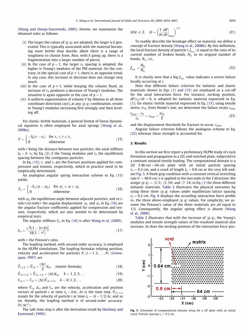
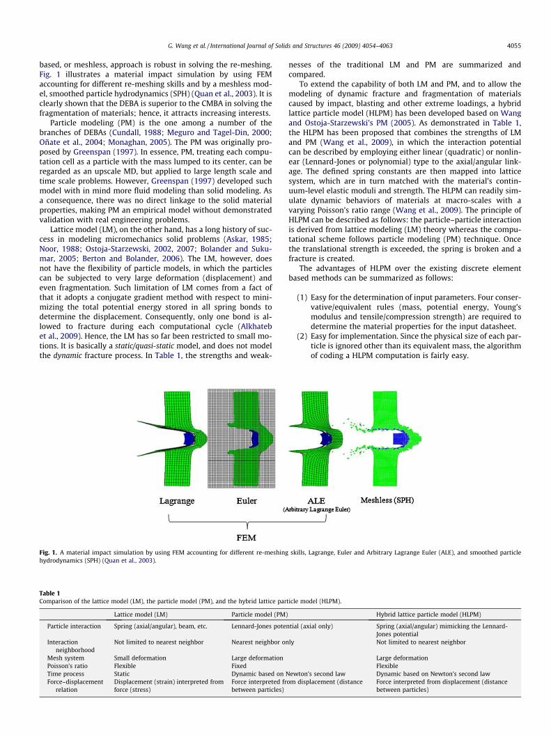
Fig. 5. Schematic of computational domain setup for a 2D plate with an initialcrack. Particle spacing r0 ¼ 0:2 cm.
G. Wang et al. / International Journal of Solids and Structures 46 (2009) 4054–4063 4059
(Wang and Ostoja-Starzewski, 2005). Herein, we summarize theobtained rules as follows:
(i) The larger the values of ðp; qÞ are adopted, the larger is E gen-erated. This is typically associated with the material becom-ing more brittle than ductile, albeit there is a range oftoughness to choose from. Also, with E going up, there is afragmentation into a larger number of pieces.
(ii) In the case of p ¼ 1, the larger r0 spacing is adopted, thehigher is Young’s modulus of the PM material. On the con-trary, in the special case of p – 1, there is an opposite trend.In any case, this increase or decrease does not change verymuch.
(iii) In the case of p – 1, while keeping the volume fixed, anincrease of r0 produces a decrease of Young’s modulus. Thesituation is again opposite in the case of p ¼ 1.
(iv) A uniform augmentation of volume V by dilation in all threecoordinate directions (xyz), at any ðp; qÞ combination, resultsin Young’s modulus increasing first strongly and then level-ing off.
For elastic–brittle materials, a general format of linear dynami-cal equation is often employed for axial springs (Wang et al.,2008a),
F ¼�S0ðr � r0Þ for rc 6 r 6 rt
0 otherwise
�ð15Þ
with r being the distance between two particles, the axial stiffnessS0 ¼ E � r0 by Eq. (2), E the Young modulus and r0 the equilibriumspacing between the contiguous particles.
In Eq. (15), rc and rt are the fracture positions applied for com-pression and tension, respectively, which in practice need to beempirically determined.
An analogous angular spring interaction scheme to Eq. (15)yields,
Fb ¼�Suðu�u0Þ for uc 6 u 6 ut
0 otherwise
�ð16Þ
with u0 the equilibrium angle between adjacent particles, and ce:i-talic>/ce:italic> the angular displacement. uc and ut in Eq. (16) arethe angular fracture coefficients applied for compression and ten-sion, respectively, which are also needed to be determined byempirical tests.
The angular stiffness Su in Eq. (16) is after Wang et al. (2009),
Su ¼ffiffiffi3pð1� 3mÞEr2
0
18ð1� m2Þ ð17Þ
with m the Poisson’s ratio.The leapfrog method, with second-order accuracy, is employed
in the HLPM simulations. The leapfrog formulas relating position,velocity and acceleration for particles Pi ði ¼ 1;2; . . . ;NÞ (Green-span, 1997) are
~Vi;1=2 ¼ ~Vi;0 þðDtÞ
2~ai;0 ðstarter formulaÞ ð18Þ
~Vi;kþ1=2 ¼ ~Vi;k�1=2 þ ðDtÞ~ai;k; k ¼ 1;2;3; . . . ð19Þ~ri;kþ1 ¼~ri;k þ ðDtÞ~Vi;kþ1=2; k ¼ 0;1;2; . . . ð20Þ
where ~Vi;k; ~ai;k and~ri;k are the velocity, acceleration and positionvectors of particle i at time tk ¼ kDt, Dt is the time step. ~Vi;kþ1=2
stands for the velocity of particle i at time tk ¼ ðkþ 1=2ÞDt, and soon. Notably, the leapfrog method is of second-order accuracy:OððDtÞ2Þ.
The safe time step is after the derivation result by Hockney andEastwood (1999):
XDt � 2; X ¼ 1m
dFdr
��������max
� �1=2
ð21Þ
To readily describe the breakage effect on material, we define aconcept of fracture density (Wang et al., 2008b). By this definition,the local fracture density of particle i; fiden:
, is equal to the ratio of itscurrent number of broken bonds, Nbi
to its original number ofbonds, Noi
, i.e.,
fiden:¼ Nbi
Noi
ð22Þ
It is clearly seen that a big fiden:value indicates a severe failure
locally occurring at i.Note that different failure criterion for inelastic and elastic
materials shown in Eqs. (1) and (15) are employed as a cut-offfor the axial interaction force. For instance, necking position,dFðrdÞ=dr ¼ 0, is adopted for inelastic material expressed in Eq.(1); for elastic–brittle material expressed in Eq. (15), using tensilestress, rTS, from Hooke’s law, we determine the failure strain emax
rmax � r0
r0¼ emax ¼
rTS
Eð23Þ
and the displacement threshold for fracture to occur, rmax.Angular failure criterion follows the analogous scheme to Eq.
(22) whereas shear strength is accounted for.
3. Results
In this section we first report a preliminary HLPM study of crackformation and propagation in a 2D, end-notched plate, subjected toa constant uniaxial tensile loading. The computational domain is a2D 3:46 cm� 64 cm plate with an initial particle spacingr0 ¼ 0:2 cm, and a crack of length l0 ¼ 0:8 cm at the very left end;see Fig. 5. A fixed-grip condition with a constant vertical stretchingrate V ¼ 40:0 cm=s is applied to the two ends in the Y direction. Weassign ðp; qÞ ¼ ð3;5Þ; ð5;10Þ and ð7;14Þ in Eq. (1) for three differentinelastic materials. Table 2 illustrates the physical outcomes byusing these three ðp; qÞ values under equilibrium lattice spacingr0 ¼ 0:2 cm. Fig. 6 displays the according interaction force profilevs. the three above-employed ðp; qÞ values. For simplicity, we as-sume the Poisson’s ratios of the three materials are all equal to1/3. Consequently, the angular spring effect is absent (Wanget al., 2009).
Table 2 illustrates that with the increase of ðp; qÞ, the Young’smodulus and tensile strength values of the resultant material alsoincrease. So does the necking position of the interaction force pro-

Table 2Physical outcomes with ðp; qÞ ¼ ð3;5Þ; ð5;10Þ and ð7;14Þ under equilibrium latticespacing r0 ¼ 0:2 cm.
ðp; qÞ (3,5) (5,10) (7,14)G 2:473� 107 1:781� 106 1:102� 105
H 9:892� 105 5:698� 102 1.411
E (GPa) 15.457 69.557 150.706rTS ðMN=m2Þ 86.205 263.570 441.534Necking position 1:29 � r0 1:15 � r0 1:11 � r0
Fig. 6. Interaction force of HLPM under r0 ¼ 0:2 cm, withðp; qÞ ¼ ð3;5Þ; ð5;10Þ and ð7;14Þ.
Fig. 7. Time-dependent fracture propagation of 2D plate with an initial crack, forductile, ðp; qÞ ¼ ð5;10Þ. Stretching rate = 40 cm/s. (a) t ¼ 7:08 ms, (b) t ¼ 7:14 ms,and (c) final crack pattern.
4060 G. Wang et al. / International Journal of Solids and Structures 46 (2009) 4054–4063
file shown in Fig. 6 as well as in Table 2. This indicates that thematerial with big ðp; qÞ behave in low ductility and vice versa.Among these three materials indicated by the associated ðp; qÞ, ifwe label ðp; qÞ ¼ ð3;5Þ as a ductile one (with high ductility), thenðp; qÞ ¼ ð5;10Þ and ð7;14Þ are in order labeled comparatively morebrittle ones (with low ductility).
Fig. 7 shows the different stages of the crack propagation, fromthe initial crack formation, to the propagation, and to the finalcrack pattern, for the material, ðp; qÞ ¼ ð3;5Þ, with high ductility.Figs. 8 and 9 show, respectively, the similar stages forðp; qÞ ¼ ð5;10Þ; ð7;14Þ, with comparatively low ductility.
Comparing Figs. 7–9, we observe:
(i) Crack develops sooner and propagates faster in materialwith low ductility (Fig. 8) than in material with high ductil-ity (Fig. 7).
(ii) For low-ductility material, crack propagation tends to behavein an unstable manner by taking a zigzag path with varyingspeed (Figs. 8 and 9(c)). For high-ductility material, we observea largely steady state growth with a smooth path (Fig. 7(c)).
Fig. 10 shows a zoomed section of the plate during the propaga-tion stage, for comparatively the most brittle case among the threeones with ðp; qÞ ¼ ð7;14Þ. It is observed that there are micro-cracksforming in a region ahead of the main crack (marked by circle andellipses), attracting the main crack toward it, thus creating a zigzagpath. This phenomenon was indeed observed in brittle-like materi-als, and not in ductile-like materials (Abraham, 1997). Fracture ofthis type is called a brittle fracture. We observe that the HLPM cantruthfully capture this delicate phenomenon by simply prescribinga Lennard-Jones-type potential that corresponds to brittle materials.Hence the HLPM can serve an important function of correctly mod-eling the time dependent ductile and brittle crack propagation.
Next, we apply the HLPM to the investigation of some structureretrofitting ideas. First, we investigate an elastic–brittle beam sub-ject to a point load at mid-span, with the two ends supported withpermission of horizontal movement. The load is actually applied asa downward displacement at the constant rate of 50 cm/s. Thetwo-dimensional beam is of the dimension 12.7 cm in length and1.27 in thickness, with material properties corresponding toYoung’s modulus 3.0 GPa, and tensile strength 60 MPa. The dy-namic interaction follows linear elastic formulas as described inEq. (15). In Fig. 10, we present the deformation of the beam att ¼ 5:6 ms. We observe that the failure happens in the form of azigzag fracture below the point load. The HLPM simulated crackpattern seems to agree well with the similar simulation by Cusatisand Cedolin (2006).
To investigate the retrofitting schemes, we protect the mainstructure as shown in Fig. 11 by a high-ductility material eitheron top, or at bottom of the beam, as shown in Fig. 12(a) and (b).The high-ductility material is characterized by ðp; qÞ ¼ ð3;5Þ, whichcorresponds to ðE;rTSÞ ¼ ð15:5 GPa;86:2 MPaÞ, and a necking posi-tion equal to rd ¼ 1:29r0, see Fig. 5. The thickness of this ductilematerial is 0.3 cm. Applying the same loading condition, we dem-onstrate the result of simulation in Fig. 13(a) and (b).
Fig. 13(a) and (b) shows the result with the retrofitted layer onthe top and at the bottom, at t ¼ 5:6 ms. From Fig. 13(a), we
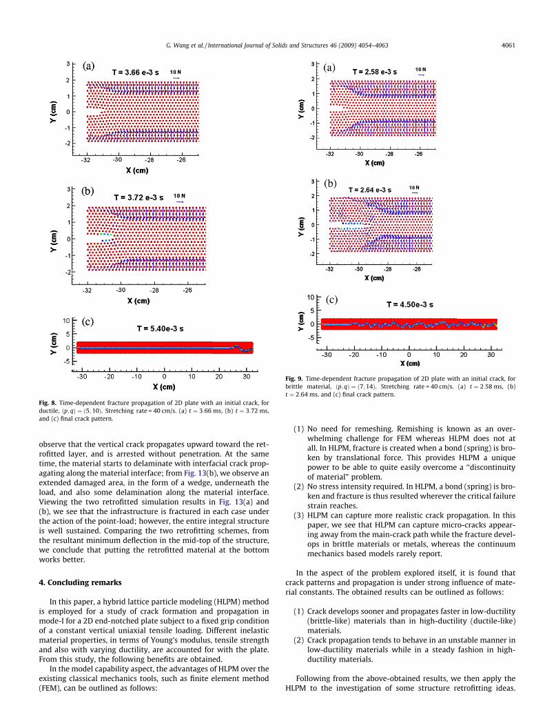
Fig. 8. Time-dependent fracture propagation of 2D plate with an initial crack, forductile, ðp; qÞ ¼ ð5;10Þ. Stretching rate = 40 cm/s. (a) t ¼ 3:66 ms, (b) t ¼ 3:72 ms,and (c) final crack pattern.
Fig. 9. Time-dependent fracture propagation of 2D plate with an initial crack, forbrittle material, ðp; qÞ ¼ ð7;14Þ. Stretching rate = 40 cm/s. (a) t ¼ 2:58 ms, (b)t ¼ 2:64 ms, and (c) final crack pattern.
G. Wang et al. / International Journal of Solids and Structures 46 (2009) 4054–4063 4061
observe that the vertical crack propagates upward toward the ret-rofitted layer, and is arrested without penetration. At the sametime, the material starts to delaminate with interfacial crack prop-agating along the material interface; from Fig. 13(b), we observe anextended damaged area, in the form of a wedge, underneath theload, and also some delamination along the material interface.Viewing the two retrofitted simulation results in Fig. 13(a) and(b), we see that the infrastructure is fractured in each case underthe action of the point-load; however, the entire integral structureis well sustained. Comparing the two retrofitting schemes, fromthe resultant minimum deflection in the mid-top of the structure,we conclude that putting the retrofitted material at the bottomworks better.
4. Concluding remarks
In this paper, a hybrid lattice particle modeling (HLPM) methodis employed for a study of crack formation and propagation inmode-I for a 2D end-notched plate subject to a fixed grip conditionof a constant vertical uniaxial tensile loading. Different inelasticmaterial properties, in terms of Young’s modulus, tensile strengthand also with varying ductility, are accounted for with the plate.From this study, the following benefits are obtained.
In the model capability aspect, the advantages of HLPM over theexisting classical mechanics tools, such as finite element method(FEM), can be outlined as follows:
(1) No need for remeshing. Remishing is known as an over-whelming challenge for FEM whereas HLPM does not atall. In HLPM, fracture is created when a bond (spring) is bro-ken by translational force. This provides HLPM a uniquepower to be able to quite easily overcome a ‘‘discontinuityof material” problem.
(2) No stress intensity required. In HLPM, a bond (spring) is bro-ken and fracture is thus resulted wherever the critical failurestrain reaches.
(3) HLPM can capture more realistic crack propagation. In thispaper, we see that HLPM can capture micro-cracks appear-ing away from the main-crack path while the fracture devel-ops in brittle materials or metals, whereas the continuummechanics based models rarely report.
In the aspect of the problem explored itself, it is found thatcrack patterns and propagation is under strong influence of mate-rial constants. The obtained results can be outlined as follows:
(1) Crack develops sooner and propagates faster in low-ductility(brittle-like) materials than in high-ductility (ductile-like)materials.
(2) Crack propagation tends to behave in an unstable manner inlow-ductility materials while in a steady fashion in high-ductility materials.
Following from the above-obtained results, we then apply theHLPM to the investigation of some structure retrofitting ideas.

Fig. 10. Zooming of a HLPM simulated fracture during the propagation stage, at t ¼ 3:3 ms, for brittle material, ðp; qÞ ¼ ð7;14Þ.
Fig. 11. HLPM simulation of failure of an elastic–brittle beam subject to a constantrate deformation at mid-span. Deformation rate = 50 cm/s. t ¼ 5:6 ms.
Fig. 12. An elastic–brittle plate coated with nonlinear ductile material: (a)retrofitted layer on the top and (b) retrofitted layer at the bottom.
Fig. 13. HLPM simulated failure of an elastic–brittle plate coated with retrofittingmaterial on top and at bottom, and subjected to a constant rate deformation at mid-span, (a) on top and (b) at bottom. Deformation rate = 50 cm/s. t ¼ 5:6 ms.
4062 G. Wang et al. / International Journal of Solids and Structures 46 (2009) 4054–4063
We select putting a retrofitted material layer on the top and at thebottom of the infrastructure to find out a better protective effect.We conclude that integral structure with retrofitted material atthe bottom produces a minimum deflection when subject to apoint-load in the mid-span. The significance of this research mayhelp guide to fabricate a high-resistance retrofitting layered struc-ture optimally comprised of different materials. This fabricatedenforcement structure is then coated to the infrastructure to
effectively improve the performance of the retrofitting of failinginfrastructure. In this paper, merely a preliminary simulation is at-tempted to identify the validation of this idea. We will report thedetailed research progress of this topic in a separate paper.
Acknowledgments
This work was partially supported by the funding received un-der a subcontract from the Department of Homeland Security-sponsored Southeast Region Research Initiative (SERRI) at the

G. Wang et al. / International Journal of Solids and Structures 46 (2009) 4054–4063 4063
Department of Energy’s Oak Ridge National Laboratory, USA. Theauthors acknowledge the partial support for this research byONR Grant No. N00014-07-1-1010, Office of Naval Research, SolidMechanics Program (Dr. Yapa D.S. Rajapakse, Program Manager).
References
Abraham, F.F., 1997. Some New Directions in Science on Computers. WorldScientific, Singapore, pp. 91–113.
Alkhateb, H., Al-Ostaz, A., Alzebdeh, K.I., 2009. Developing a stochastic model topredict the strength and crack path of random composites. Composites B 40, 7–16.
Al-Ostaz, A., Jasiuk, I., 1997. Crack initiation and propagation in materials withrandomly distributed holes. Engineering Fracture Mechanics 58, 395–420.
Ashby, M.F., Jones, D.R.H., 1980. Engineering Materials 1: An Introduction to TheirProperties and Applications. Pergamon Press, Oxford.
Askar, A., 1985. Lattice Dynamical Foundations of Continuum Theories. WorldScientific, Singapore.
Berton, S., Bolander, J.E., 2006. Crack band model of fracture in irregular lattices.Computer Methods in Applied Mechanics and Engineering 195, 7172–7181.
Berton, S., Bolander, J.E., 2006. Crack band model of fracture in irregular lattices.Computer Methods in Applied Mechanics and Engineering 195, 7172–7181.
Bolander, J.E., Sukumar, N., 2005. Irregular lattice model for quasi-static crackpropagation. Physical Reviews B 71, 094106.
Cundall, P.A., 1988. Computer simulations of dense sphere assembles.Micromechanics of Granular Materials, 113–123.
Cusatis, G., Cedolin, L., 2006. Two-scale study of concrete fracturing behavior.Engineering Fracture Mechanics 74, 3–17.
Greenspan, D., 1997. Particle Modeling. Birkhäuser Publishing, Basel.Hockney, R.W., Eastwood, J.W., 1999. Computer Simulation Using Particles. Institute
of Physics Publishing.
Meguro, M., Tagel-Din, H., 2000. Applied element method for structural analysis:theory and application for linear materials. Structural Engineering/EarthquakeEngineering, JSCE 17 (1), 1–14.
Monaghan, J., 2005. Smoothed particle hydrodynamics. Reports on Progress inPhysics 68 (1), 1703–1759.
Noor, A.K., 1988. Continuum modeling for repetitive lattice structures. AppliedMechanics in Reviews 41 (7), 285–296.
Oñate, E., Idelsohn, S.R., Pin, F.D., Aubry, R., 2004. The particle finite elementmethod: an overview. International Journal Computational Method 1 (2), 267–307.
Ostoja-Starzewski, M., 2002. Lattice models in micromechanics. Applied Mechanicsin Reviews 55 (1), 35–60.
Ostoja-Starzewski, M., 2007. Microstructural randomness and scaling in mechanicsof materials. In: Modern Mechanics and Mathematics Series. Chapman & Hall/CRC Press/Taylor & Francis, London/Boca Raton, FL/London.
Ostoja-Starzewski, M., Wang, G., 2006. Particle modeling of random crack patternsin epoxy plates. Probabilistic Engineering Mechanics 21, 267–275.
Quan, X., Birnbaum, N.K., Cowler, M.S., Gerber, B.I., Clegg, R.A., Hayhurst, C.J., 2003.Numerical simulation of structural deformation under shock and impact loadsusing a coupled multi-solver approach. In: 5th Asia-Pacific Conference on Shockand Impact Loads on Structures, November 12–14, Human, China.
Wang, G., 2009. Particle modeling of polymeric material indentation study.Engineering Fracture Mechanics 76, 1386–1395.
Wang, G., Ostoja-Starzewski, M., 2005. Particle modeling of dynamic fragmentation– I: theoretical considerations. Computational Materials Science 33, 429–442.
Wang, G., Al-Ostaz, A., Cheng, A.H.-D., Mantena, P.R., 2008a. Particle modeling of apolymeric material (nylon-6,6) due to the impact of a rigid indenter.Computational Materials Science 44, 449–463.
Wang, G., Radziszewski, P., Ouellet, J., 2008b. Particle modeling simulation ofthermal effects on ore breakage. Computational Materials Science 43, 892–901.
Wang, G., Al-Ostaz, A., Cheng, A.H.-D., Mantena, P.R., 2009. Hybrid lattice particlemodeling: theoretical considerations for a 2-D elastic spring network fordynamic fracture simulations. Computational Materials Science 44, 1126–1134.