Embed Size (px)
Citation preview

International Journal of Mechanical Engineering and Robotics Research Vol. 9, No. 9, September 2020
© 2020 Int. J. Mech. Eng. Rob. Res 1253doi: 10.18178/ijmerr.9.9.1253-1263
A Machine Learning Approach of Lattice Infill
Pattern for Increasing Material Efficiency in
Additive Manufacturing Processes
Jonnel D. Alejandrino, Ronnie S. Concepcion II, Sandy C. Lauguico, Rogelio Ruzcko Tobias, Lenardo
Venancio, Dailyne Macasaet, Argel A. Bandala, and Elmer P. Dadios De La Salle University/Gokongwei College of Engineering, Manila, Philippines
Email: [email protected], {ronnie_concepcionii, sandy_lauguico, rogelio_tobias, leonardo_venancio,
dailyne_macasaet, argel.bandala, elmer.dadios}@dlsu.edu.ph
Abstract— Additive Manufacturing (AM) has become
ubiquitous in manufacturing three-dimensional objects
through 3D printing. Traditional analytical models are still
widely utilized for low – cost 3D Printing, which is deficient
in terms of process, structure, property and performance
relationship for AM. This paper focuses on the introduction
of a new infill pattern – the lattice infill to increase material
efficiency of 3D prints, coupled with Machine Learning (ML)
technique to address geometric corrections in modelling the
shape deviations of AM. Encompassed by ML algorithms,
the neural network (NN) is used to handle the large dataset
of the system. The 3D coordinates of the proposed infill
pattern are extracted as the input of the NN model. The
optimization technique of scaled conjugate gradient (SCG)
is the algorithm used to train the feedforward ANN, and
sigmoidal function was used as the activation type for
output neurons. There is 0.00776625 cross-entropy (CE)
performance and 98.8% accuracy during network training.
The trained network is implemented to STL file for
geometric corrections of the lattice infill pattern then made
in a 3D printer slicing software. Conventional designs such
as the cubic and grid infill pattern were also made for
comparison. Engineering simulation software were used to
simulate all three infill patterns, to measure approximate
product weight, stress performance and displacement, given
that there is an external force applied. Comparisons showed
that the new infill pattern is more efficient than
conventional infill patterns saving material up to 61.3%.
Essentially increasing the amount of prints produced per
spool by 2.5 times. The structure of the proposed design can
also resist up to 1.6kN of compressive load prior to breaking.
Index Terms— machine learning, additive manufacturing,
infill, lattice
I.
INTRODUCTION
The technology of creating physical 3D objects from a
virtual computer assisted design through sequential
addition of material without the aid of external tooling is
called Additive Manufacturing (AM) or commonly
known as 3D printing. Opposing the subtractive
manufacturing, which creates 3D objects by material
Manuscript received July 21,
2019; revised August
7, 2020.
removal. This technology is more acceptable in cost,
speed, quality and impact. It is customarily used in rapid
prototyping and manufacturing, production of spare parts,
small volume and very complex work pieces because of
its advantages. It allows the rapid creation of sustainable
objects and has been utilized to fabricate lightweight
parts [1].
For good production, additive manufacturing (AM) has
been using infill patterns to reduce the weight of the
product and to save up material expend as low as possible
but not trading the quality [2]. It is accomplished with the
use of cellular materials with a regular and periodic
microstructure [3].
The interior microstructure of an object printed is
called, “infill”. It follows a regular structures and patterns.
Usually advanced slicing software is pre-loaded with
infill patterns for the user to select along with a specific
volume percentage [4]. The infill pattern and volume
percentage significantly influence the printing process as
well as physical properties of the printed object [5].
Greater the preferred volume percentage the greater the
material and the longer the print time that leads to a more
resistant print [6].
Even though there are many available types of infill
due to AM advancement, there are several types that are
commonly used because of their efficiency and
comfortability compared to others. The grid or also
known as rectangular infill pattern is the traditional and
general purpose pattern being used nowadays [7]. At the
same time Fused Deposition Modeling (FDM) meanwhile,
is considered as one of the most productive technology
typically used in low-cost 3D printers. A software will
process an STL or CAD (computer-aided design) file,
then geometrically slicing and conditioning the model
generating GCODEs, and finally running the generated
GCODEs through the printer before printing begins [8].
The mechanism approach of the it uses a plastic filament
that is pushed through a heated extrusion nozzle melting
[9]. This provide distinction to SLA (stereolithography)
process, which is characterized by printing layer by layer
using photo-polymerizable liquid resin through ultraviolet
light [10].
International Journal of Mechanical Engineering and Robotics Research Vol. 9, No. 9, September 2020
© 2020 Int. J. Mech. Eng. Rob. Res 1254
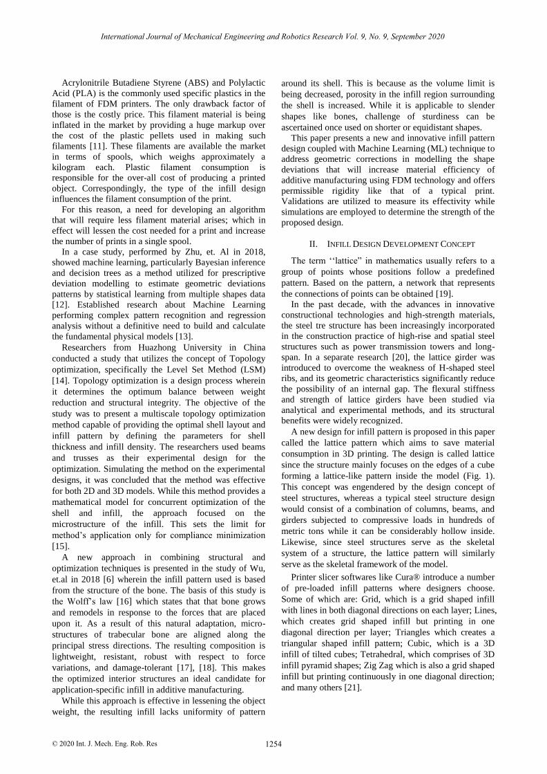
Acrylonitrile Butadiene Styrene (ABS) and Polylactic
Acid (PLA) is the commonly used specific plastics in the
filament of FDM printers. The only drawback factor of
those is the costly price. This filament material is being
inflated in the market by providing a huge markup over
the cost of the plastic pellets used in making such
filaments [11]. These filaments are available the market
in terms of spools, which weighs approximately a
kilogram each. Plastic filament consumption is
responsible for the over-all cost of producing a printed
object. Correspondingly, the type of the infill design
influences the filament consumption of the print.
For this reason, a need for developing an algorithm
that will require less filament material arises; which in
effect will lessen the cost needed for a print and increase
the number of prints in a single spool.
In a case study, performed by Zhu, et. Al in 2018,
showed machine learning, particularly Bayesian inference
and decision trees as a method utilized for prescriptive
deviation modelling to estimate geometric deviations
patterns by statistical learning from multiple shapes data
[12]. Established research about Machine Learning
performing complex pattern recognition and regression
analysis without a definitive need to build and calculate
the fundamental physical models [13].
Researchers from Huazhong University in China
conducted a study that utilizes the concept of Topology
optimization, specifically the Level Set Method (LSM)
[14]. Topology optimization is a design process wherein
it determines the optimum balance between weight
reduction and structural integrity. The objective of the
study was to present a multiscale topology optimization
method capable of providing the optimal shell layout and
infill pattern by defining the parameters for shell
thickness and infill density. The researchers used beams
and trusses as their experimental design for the
optimization. Simulating the method on the experimental
designs, it was concluded that the method was effective
for both 2D and 3D models. While this method provides a
mathematical model for concurrent optimization of the
shell and infill, the approach focused on the
microstructure of the infill. This sets the limit for
method’s application only for compliance minimization
[15].
A new approach in combining structural and
optimization techniques is presented in the study of Wu,
et.al in 2018 [6] wherein the infill pattern used is based
from the structure of the bone. The basis of this study is
the Wolff’s law [16] which states that that bone grows
and remodels in response to the forces that are placed
upon it. As a result of this natural adaptation, micro-
structures of trabecular bone are aligned along the
principal stress directions. The resulting composition is
lightweight, resistant, robust with respect to force
variations, and damage-tolerant [17], [18]. This makes
the optimized interior structures an ideal candidate for
application-specific infill in additive manufacturing.
While this approach is effective in lessening the object
weight, the resulting infill lacks uniformity of pattern
around its shell. This is because as the volume limit is
being decreased, porosity in the infill region surrounding
the shell is increased. While it is applicable to slender
shapes like bones, challenge of sturdiness can be
ascertained once used on shorter or equidistant shapes.
This paper presents a new and innovative infill pattern
design coupled with Machine Learning (ML) technique to
address geometric corrections in modelling the shape
deviations that will increase material efficiency of
additive manufacturing using FDM technology and offers
permissible rigidity like that of a typical print.
Validations are utilized to measure its effectivity while
simulations are employed to determine the strength of the
proposed design.
II. INFILL DESIGN DEVELOPMENT CONCEPT
The term ‘‘lattice” in mathematics usually refers to a
group of points whose positions follow a predefined
pattern. Based on the pattern, a network that represents
the connections of points can be obtained [19].
In the past decade, with the advances in innovative
constructional technologies and high-strength materials,
the steel tre structure has been increasingly incorporated
in the construction practice of high-rise and spatial steel
structures such as power transmission towers and long-
span. In a separate research [20], the lattice girder was
introduced to overcome the weakness of H-shaped steel
ribs, and its geometric characteristics significantly reduce
the possibility of an internal gap. The flexural stiffness
and strength of lattice girders have been studied via
analytical and experimental methods, and its structural
benefits were widely recognized.
A new design for infill pattern is proposed in this paper
called the lattice pattern which aims to save material
consumption in 3D printing. The design is called lattice
since the structure mainly focuses on the edges of a cube
forming a lattice-like pattern inside the model (Fig. 1).
This concept was engendered by the design concept of
steel structures, whereas a typical steel structure design
would consist of a combination of columns, beams, and
girders subjected to compressive loads in hundreds of
metric tons while it can be considerably hollow inside.
Likewise, since steel structures serve as the skeletal
system of a structure, the lattice pattern will similarly
serve as the skeletal framework of the model.
Printer slicer softwares like Cura® introduce a number
of pre-loaded infill patterns where designers choose.
Some of which are: Grid, which is a grid shaped infill
with lines in both diagonal directions on each layer; Lines,
which creates grid shaped infill but printing in one
diagonal direction per layer; Triangles which creates a
triangular shaped infill pattern; Cubic, which is a 3D
infill of tilted cubes; Tetrahedral, which comprises of 3D
infill pyramid shapes; Zig Zag which is also a grid shaped
infill but printing continuously in one diagonal direction;
and many others [21].

International Journal of Mechanical Engineering and Robotics Research Vol. 9, No. 9, September 2020
© 2020 Int. J. Mech. Eng. Rob. Res 1255
Figure 1. Zoom-out view of the lattice pattern
But all of these built-in pattern designs are printed
horizontally by layers on top of each other thus creating
vertical faces, which in effect consumes a lot of plastic
material to construct.
Meanwhile,
the studied lattice
pattern being used in construction industry for their steel
structures do not require vertical faces, while still
maintaining the pattern’s rigidity.
Fig.
2
(Lattice Infill Pattern) details the steel structure
used in the construction
industry which is used as an
inspiration for the proposed lattice infill structure. It is
noticeable that the adopted design was slightly altered by
making the beams consisted in profile, with even spaces
and supporting beams removed as a requirement for an
easy layer slicing. This structural-like pattern was used to
function as the infill pattern for 3D printing.
Figure 2. Lattice Infill Pattern
III. METHODOLOGY
The flowchart in Fig. 3 detailed the methodology used
in conducting this research. It focused on three parts:
Development of Artificial Neural Network algorithm, two
design phases, two simulation phases and one evaluation
phase.
A. Design Phase
The design phase consisted of two components:
defining of benchmark infill pattern parameters and
designing of proposed infill pattern. For consistency and
due to its simplicity, all patterns are designed to make a
100mm x 100mm x 100mm cube print. ABS filament is
used as material for 3D printing as it is one of the most
commonly used filaments by users. The study is initiated
by defining benchmark parameters allowing the
researchers to compare and analyze the obtained data and
performance of the proposed design with respect to the
reference data sheet. The researchers decided to use the
grid infill pattern to serve as the benchmark infill pattern,
since this is commonly used by 3D Printer users. The
cubic infill pattern is also utilized in this study for
additional validation. Parameters are set to 5 mm infill
line distance with 250 microns of layer thickness for the
infill, and a shell thickness of 2mm for the cube surfaces.
Testing and simulation of both benchmark and proposed
using Lulzbot Cura® printer slicing software.
Figure 3. Flowchart of the Research Methodology
Fig. 4
presented the zoom-in view of both the grid (a)
and cubic (b) infill patterns. Differences of the two is
difficult to ascertain at a glance, but noticeable on the
edges. Uneven triangles are seen on the edges of cubic
pattern model, while equilateral ones are surrounding the
grid pattern model. This is due to the design of the cubic
pattern, wherein it utilizes tilted cubes.
International Journal of Mechanical Engineering and Robotics Research Vol. 9, No. 9, September 2020
© 2020 Int. J. Mech. Eng. Rob. Res 1256
(a)
(b) (c)
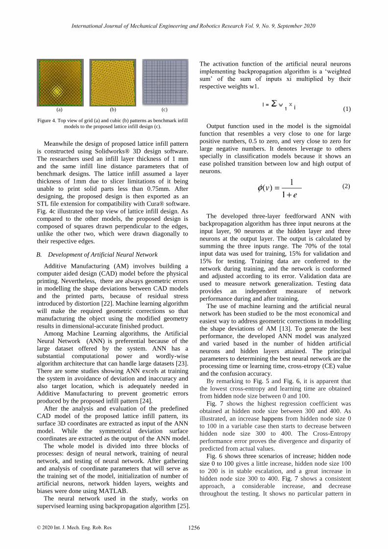
Figure 4. Top view of grid (a) and cubic (b) patterns as benchmark infill models to the proposed lattice infill design (c).
Meanwhile the design of proposed lattice infill pattern
is constructed using Solidworks® 3D design software.
The researchers used an infill layer thickness of 1 mm
and the same infill line distance
parameters that of
benchmark designs. The lattice infill assumed a layer
thickness of 1mm due to slicer limitations of it being
unable to print solid parts less than 0.75mm. After
designing, the proposed design is then exported as an
STL file extension for compatibility
with Cura® software.
Fig.
4c
illustrated the top view of lattice infill design. As
compared to the other models, the proposed design is
composed of squares drawn perpendicular to the edges,
unlike the other two, which were drawn diagonally to
their respective edges.
B. Development of Artificial Neural Network
Additive Manufacturing (AM) involves building a
computer aided design (CAD) model before the physical
printing. Nevertheless, there are always geometric errors
in modelling the shape deviations between CAD models
and the printed parts, because of residual stress
introduced by distortion [22]. Machine learning algorithm
will make the required geometric corrections so that
manufacturing the object using the modified geometry
results in dimensional-accurate finished product.
Among Machine Learning algorithms, the Artificial
Neural Network (ANN) is preferential because of the
large dataset offered by the system. ANN has a
substantial computational power and wordly-wise
algorithm architecture that can handle large datasets [23].
There are some studies showing ANN excels at training
the system in avoidance of deviation and inaccuracy and
also target location, which is adequately needed in
Additive Manufacturing to prevent geometric errors
produced by the proposed infill pattern [24].
After the analysis and evaluation of the predefined
CAD model of the proposed lattice infill pattern, its
surface 3D coordinates are extracted as input of the ANN
model. While the symmetrical deviation surface
coordinates are extracted as the output of the ANN model.
The whole model is divided into three blocks of
processes: design of neural network, training of neural
network, and testing of neural network. After gathering
and analysis of coordinate parameters that will serve as
the training set of the model, initialization of number of
artificial neurons, network hidden layers, weights and
biases were done using MATLAB.
The neural network used in the study, works on
supervised learning using backpropagation algorithm [25].
The activation function of the artificial neural neurons
implementing backpropagation algorithm is a ‘weighted
sum’ of the sum of inputs xi multiplied by their
respective weights w1.
(1)
(1)
Output function used in the model is the sigmoidal
function that resembles a very close to one for large
positive numbers, 0.5 to zero, and very close to zero for
large negative numbers. It denotes leverage to others
specially in classification models because it shows an
ease polished transition between low and high output of
neurons.
(2)
The developed three-layer feedforward ANN with
backpropagation algorithm has three input neurons at the
input layer, 90 neurons at the hidden layer and three
neurons at the output layer. The output is calculated by
summing the three inputs range. The 70% of the total
input data was used for training, 15% for validation and
15% for testing. Training data are conferred to the
network during training, and the network is conformed
and adjusted according to its error. Validation data are
used to measure network generalization. Testing data
provides an independent measure of network
performance during and after training.
The use of machine learning and the artificial neural
network has been studied to be the most economical and
easiest way to address geometric corrections in modelling
the shape deviations of AM [13]. To generate the best
performance, the developed ANN model was analyzed
and varied based in the number of hidden artificial
neurons and hidden layers attained. The principal
parameters to determining the best neural network are the
processing time or learning time, cross-etropy (CE) value
and the confusion accuracy.
By remarking to Fig. 5 and Fig. 6, it is apparent that
the lowest cross-entropy and learning time are obtained
from hidden node size between 0 and 100.
Fig. 7 shows the highest regression coefficient was
obtained at hidden node size between 300 and 400. As
illustrated, an increase happens from hidden node size 0
to 100 in a variable case then starts to decrease between
hidden node size 300 to 400. The Cross-Entropy
performance error proves the divergence and disparity of
predicted from actual values.
Fig. 6 shows three scenarios of increase; hidden node
size 0 to 100 gives a little increase, hidden node size 100
to 200 is in stable escalation, and a great increase in
hidden node size 300 to 400. Fig. 7 shows a consistent
approach, a considerable increase, and decrease
throughout the testing. It shows no particular pattern in
International Journal of Mechanical Engineering and Robotics Research Vol. 9, No. 9, September 2020
© 2020 Int. J. Mech. Eng. Rob. Res 1257
confusion accuracy in increasing the magnitude of hidden
artificial nodes.
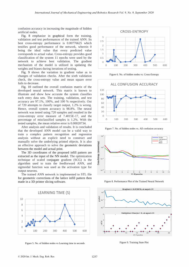
Fig. 8 emphasize in graphical form the training,
validation and test performances of the trained ANN. Its
best cross-entropy performance is 0.00776625 which
testifies good performance of the network, wherein 0
being the ideal value that every predicted value
corresponds to actual value. Cross-entropy provides good
classification of the system 11 epochs were used by the
network to achieve best validation. The gradient
mechanism of the model is utilized in updating the
weights and biases during iterations of testing.
Fig. 9 shows the variation in gradient value as to
changes of validation checks. After the sixth validation
check, the cross-entropy value and mean square error
fails to decrease.
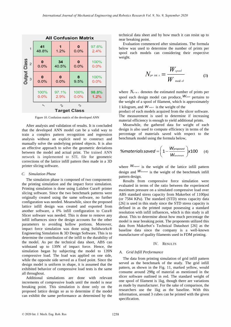
Fig. 10 outlined the overall confusion matrix of the
developed neural network. This matrix is known to
illustrate and show how accurate the system classifies
each entry data sets. The training, validation, and test
accuracy are 97.1%, 100%, and 100 % respectively. Out
of 720 attempts to classify target output, 1.2% is wrong.
Hence, overall system accuracy is 98.8%. The neural
network was tested using 720 samples and resulted in the
cross-entropy error measure of 7.4015E-17, and the
percentage of misclassified samples is 1.2%. With the
tested samples, the mean relative error is 0.00020734.
After analysis and validation of results. It is concluded
that the developed ANN model can be a valid way to
train a complex pattern recognition and regression
analysis without an explicit need to construct and
manually solve the underlying printed objects. It is also
an effective approach to solve the geometric deviations
between the model and actual print.
The 3D coordinates of the proposed infill pattern are
extracted as the input of the NN model. The optimization
technique of scaled conjugate gradient (SCG) is the
algorithm used to train the feedforward ANN, and
sigmoidal function was used as the activation type for
output neurons.
The trained ANN network is implemented to STL file
for geometric corrections of the lattice infill pattern then
made in a 3D printer slicing software.
Figure 5. No. of hidden nodes vs Learning time in seconds
Figure 6. No. of hidden nodes vs. Cross-Entropy
Figure 7. No. of hidden nodes vs. All confusion accuracy
Figure 8. Performance Plot of the Trained Neural Network
Figure 9. Training State Plot
International Journal of Mechanical Engineering and Robotics Research Vol. 9, No. 9, September 2020
© 2020 Int. J. Mech. Eng. Rob. Res 1258
Figure 10. Confusion matrix of the developed ANN
After analysis and validation of results. It is concluded
that the developed ANN model can be a valid way to
train a complex pattern recognition and regression
analysis without an explicit need to construct and
manually solve the underlying printed objects. It is also
an effective approach to solve the geometric deviations
between the model and actual print. The trained ANN
network is implemented to STL file for geometric
corrections of the lattice infill pattern then made in a 3D
printer slicing software.
C. Simulation Phase
The simulation phase is composed of two components:
the printing simulation and the impact force simulation.
Printing simulation is done using Lulzbot Cura® printer
slicing software. Since the two benchmark patterns were
originally created using the same software, no further
configuration was needed. Meanwhile, since the proposed
lattice infill design was created and exported from
another software, a 0% infill configuration to Cura®
Slicer software was needed. This is done to remove any
infill influences since the design accounts for the other
parameters to avoiding hollow portions. Moreover,
impact force simulation was done using Solidworks®
Engineering Simulation & 3D Design Software. This is to
determine the contribution of the infill to the durability of
the model. As per the technical data sheet, ABS can
withstand up to 139N of impact force. Hence, the
simulation began by subjecting the model to 139N
compressive load. The load was applied on one side,
while the opposite side served as a fixed point. Since the
design model is uniform in shape, it is assumed that the
exhibited behavior of compressive load tests is the same
all throughout.
Additional simulations are done with relevant
increments of compressive loads until the model is near
breaking point. This simulation is done only on the
proposed lattice design so as to determine if the model
can exhibit the same performance as determined by the
technical data sheet and by how much it can resist up to
near breaking point.
Evaluation commenced after simulations. The formula
below was used to determine the number of prints per
spool each models can considering their respective
weight.
(3)
where intpr sN denotes the estimated number of prints per
spool each design model can produce, spoolW pertains to
the weight of a spool of filament, which is approximately
1 kilogram, and mod elW is the weight of the
product of each models acquired from the slicer software.
The measurement is used to determine if increasing
material efficiency is enough to yield additional prints.
Meanwhile, the gathered data for weight of each
design is also used to compute efficiency in terms of the
percentage of materials saved with respect to the
benchmark model using the formula below,
% 1 100benchmark
proposedWmaterialssaved x
W (4)
where proposedW is the weight of the lattice infill pattern
design and benchmarkW is the weight of the benchmark infill
pattern design.
Results from compressive force simulation were
evaluated in terms of the ratio between the experienced
maximum pressure on a simulated compressive load over
ABS standard stress capacity from Makerbot of 1100psi
(or 7584 KPa). The standard (STD) stress capacity data
[26] is used in this study since the STD stress capacity is
defined in as the printed output possessing a standard
resolution with infill influences, which is this study is all
about. This to determine about how much percentage the
model is near breaking point. The proponents utilized this
data from Makerbot’s Technical Datasheet [26] as the
baseline data since the company is a well-known
manufacturer of quality filaments used in FDM printing.
IV. RESULTS
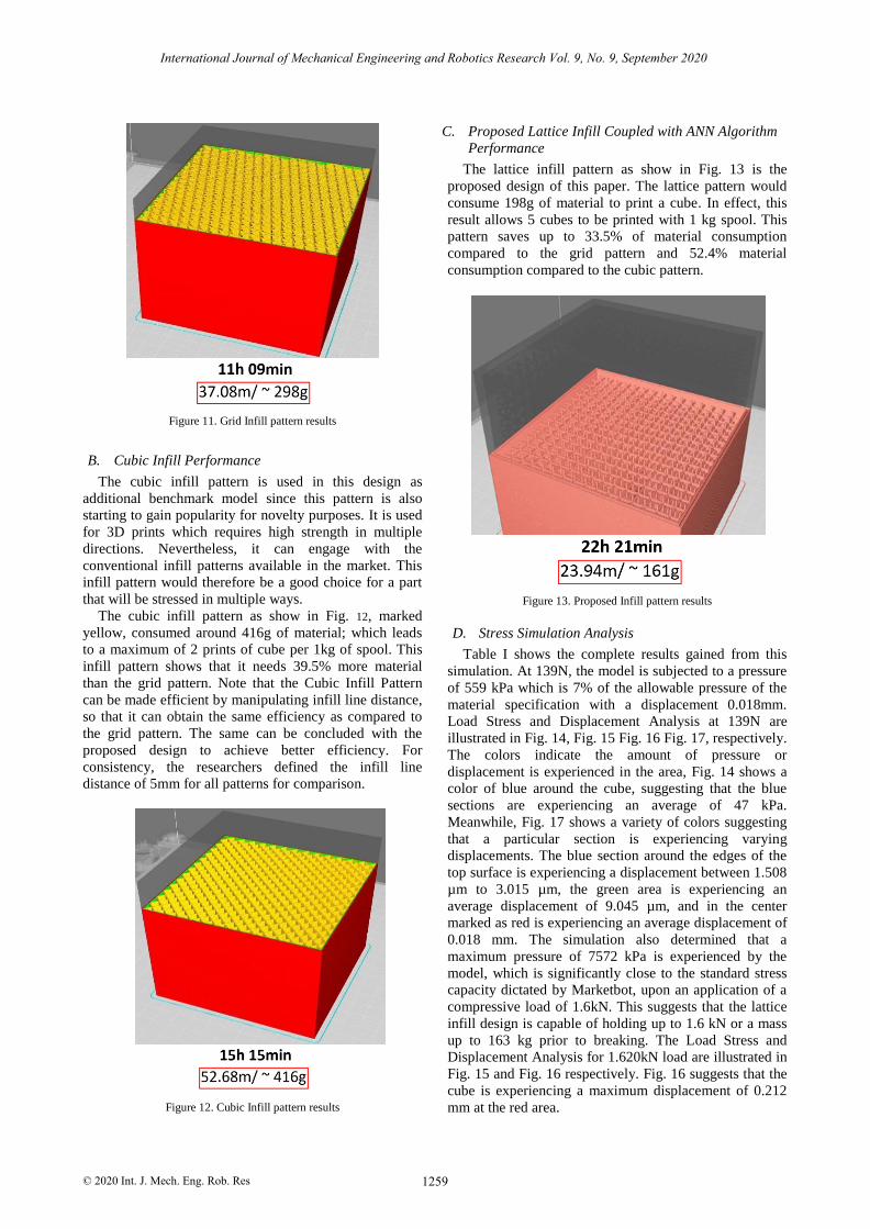
A. Grid Infill Performance
The data from printing simulation of grid infill pattern
served as the benchmark of the study. The grid infill
pattern, as shown in the Fig. 11, marked yellow, would
consume around 298g of material as mentioned in the
slicer software outlined in red. The standard weight of
one spool of filament is 1kg, though there are variations
as made by manufacturer. For the sake of comparison, the
researchers use the 1kg as the baseline. With this
information, around 3 cubes can be printed with the given
specification.
International Journal of Mechanical Engineering and Robotics Research Vol. 9, No. 9, September 2020
© 2020 Int. J. Mech. Eng. Rob. Res 1259
Figure 11. Grid Infill pattern results
B. Cubic Infill Performance
The cubic infill pattern is used in this design as
additional benchmark model since this pattern is also
starting to gain popularity for novelty purposes. It is used
for 3D prints which requires high strength in multiple
directions. Nevertheless, it can engage with the
conventional infill patterns available in the market. This
infill pattern would therefore be a good choice for a part
that will be stressed in multiple ways.
The cubic infill pattern as show in Fig. 12, marked
yellow, consumed around 416g of material; which leads
to a maximum of 2 prints of cube per 1kg of spool. This
infill pattern shows that it needs 39.5% more material
than the grid pattern. Note that the Cubic Infill Pattern
can be made efficient by manipulating infill line distance,
so that it can obtain the same efficiency as compared to
the grid pattern. The same can be concluded with the
proposed design to achieve better efficiency. For
consistency, the researchers defined the infill line
distance of 5mm for all patterns for comparison.
Figure 12. Cubic Infill pattern results
C. Proposed Lattice Infill Coupled with ANN Algorithm
Performance
The lattice infill pattern as show in Fig. 13 is the
proposed design of this paper. The lattice pattern would
consume 198g of material to print a cube. In effect, this
result allows 5 cubes to be printed with 1 kg spool. This
pattern saves up to 33.5% of material consumption
compared to the grid pattern and 52.4% material
consumption compared to the cubic pattern.
Figure 13. Proposed Infill pattern results
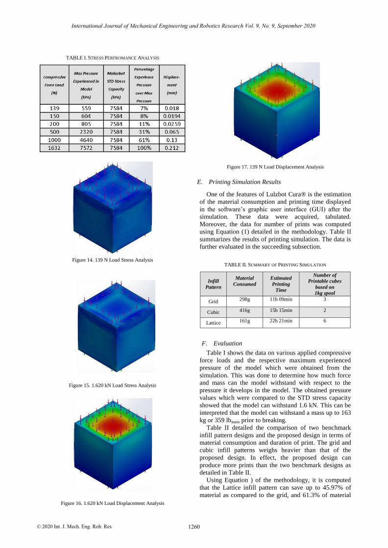
D. Stress Simulation Analysis
Table I shows the complete results gained from this
simulation. At 139N, the model is subjected to a pressure
of 559 kPa which is 7% of the allowable pressure of the
material specification with a displacement 0.018mm.
Load Stress and Displacement Analysis at 139N are
illustrated in Fig. 14, Fig. 15 Fig. 16 Fig. 17, respectively.
The colors indicate the amount of pressure or
displacement is experienced in the area, Fig. 14 shows a
color of blue around the cube, suggesting that the blue
sections are experiencing an average of 47 kPa.
Meanwhile, Fig. 17 shows a variety of colors suggesting
that a particular section is experiencing varying
displacements. The blue section around the edges of the
top surface is experiencing a displacement between 1.508
µm to 3.015 µm, the green area is experiencing an
average displacement of 9.045 µm, and in the center
marked as red is experiencing an average displacement of
0.018 mm. The simulation also determined that a
maximum pressure of 7572 kPa is experienced by the
model, which is significantly close to the standard stress
capacity dictated by Marketbot, upon an application of a
compressive load of 1.6kN. This suggests that the lattice
infill design is capable of holding up to 1.6 kN or a mass
up to 163 kg prior to breaking. The Load Stress and
Displacement Analysis for 1.620kN load are illustrated in
Fig. 15 and Fig. 16 respectively. Fig. 16 suggests that the
cube is experiencing a maximum displacement of 0.212
mm at the red area.
International Journal of Mechanical Engineering and Robotics Research Vol. 9, No. 9, September 2020
© 2020 Int. J. Mech. Eng. Rob. Res 1260
TABLE I. STRESS PERFROMANCE ANALYSIS
Figure 14. 139 N Load Stress Analysis
Figure 15. 1.620 kN Load Stress Analysis
Figure 16. 1.620 kN Load Displacement Analysis
Figure 17. 139 N Load Displacement Analysis
E.
Printing Simulation Results
One of the features of Lulzbot Cura® is the estimation
of the material consumption and printing time displayed
in the software’s graphic user interface (GUI) after the
simulation. These data were acquired, tabulated.
Moreover, the data for number of prints was computed
using Equation (1) detailed in the methodology. Table II
summarizes the results of printing simulation. The data is
further evaluated in the succeeding subsection.
TABLE II. SUMMARY OF PRINTING SIMULATION
Infill
Pattern
Material
Consumed
Estimated
Printing
Time
Number of
Printable cubes
based on
1kg spool
Grid 298g 11h 09min 3
Cubic 416g 15h 15min 2
Lattice 161g 22h 21min 6
F. Evaluation
Table I shows the data on various applied compressive
force loads and the respective maximum experienced
pressure of the model which were obtained from the
simulation. This was done to determine how much force
and mass can the model withstand with respect to the
pressure it develops in the model. The obtained pressure
values which were compared to the STD stress capacity
showed that the model can withstand 1.6 kN. This can be
interpreted that the model can withstand a mass up to 163
kg or 359 lbmass prior to breaking.
Table II detailed the comparison of two benchmark
infill pattern designs and the proposed design in terms of
material consumption and duration of print. The grid and
cubic infill patterns weighs heavier than that of the
proposed design. In effect, the proposed design can
produce more prints than the two benchmark designs as
detailed in Table II.
Using Equation ) of the methodology, it is computed
that the Lattice infill pattern can save up to 45.97% of
material as compared to the grid, and 61.3% of material
International Journal of Mechanical Engineering and Robotics Research Vol. 9, No. 9, September 2020
© 2020 Int. J. Mech. Eng. Rob. Res 1261
as compared to the cubic. Both data exceed the research
objective of 25% reduction of material consumption.
While the data proves that there is practicality in the
proposed infill design, it is also noticeable that the lattice
infill has longer printing time than the other two. The
lattice infill needs at least extra seven hours of printing as
compared to that of the benchmark infill patterns. The
lengthy printing time of the proposed design is mainly
due to the need for multiple passes in achieving the
required thickness of the infill. The nozzle diameter is
one main factor for printing the infill. The process of
printing the infill of a model is through a single pass per
layer from point A to point B. With those considerations,
the printing time of the infill is faster than the outer shell
of the model since the outer shell would require multiple
passes before shifting to the next layer. The layer width
of the infill will always follow the specified layer
thickness up to a maximum of the nozzle diameter, and
the standard nozzle diameter is between 0.4 mm to 0.5
mm. The lattice infill assumed a layer thickness of 1mm
due to slicer limitations of it being unable to print solid
parts less than 0.75mm. The slicer treated the 1mm infill
layer thickness specified in the design as a solid part,
requiring it to have multiple passes to fulfill the required
thickness before shifting to another layer resulting to a
longer printing time as compared to a regular infill
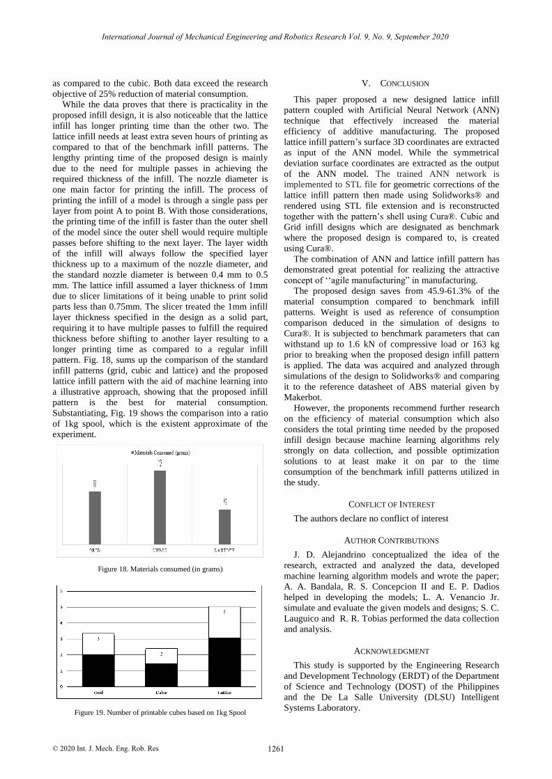
pattern. Fig. 18, sums up the comparison of the standard
infill patterns (grid, cubic and lattice) and the proposed
lattice infill pattern with the aid of machine learning into
a illustrative approach, showing that the proposed infill
pattern is the best for material consumption.
Substantiating, Fig. 19 shows the comparison into a ratio
of 1kg spool, which is the existent approximate of the
experiment.
Figure 18. Materials consumed (in grams)
Figure 19. Number of printable cubes based on 1kg Spool
V. CONCLUSION
This paper proposed a new designed lattice infill
pattern coupled with Artificial Neural Network (ANN)
technique that effectively increased the material
efficiency of additive manufacturing. The proposed
lattice infill pattern’s surface 3D coordinates are extracted
as input of the ANN model. While the symmetrical
deviation surface coordinates are extracted as the output
of the ANN model. The trained ANN network is
implemented to STL file for geometric corrections of the
lattice infill pattern then made using Solidworks® and
rendered using STL file extension and is reconstructed
together with the pattern’s shell using Cura®. Cubic and
Grid infill designs which are designated as benchmark
where the proposed design is compared to, is created
using Cura®.
The combination of ANN and lattice infill pattern has
demonstrated great potential for realizing the attractive
concept of ‘‘agile manufacturing” in manufacturing.
The proposed design saves from 45.9-61.3% of the
material consumption compared to benchmark infill
patterns. Weight is used as reference of consumption
comparison deduced in the simulation of designs to
Cura®. It is subjected to benchmark parameters that can
withstand up to 1.6 kN of compressive load or 163 kg
prior to breaking when the proposed design infill pattern
is applied. The data was acquired and analyzed through
simulations of the design to Solidworks® and comparing
it to the reference datasheet of ABS material given by
Makerbot.
However, the proponents recommend further research
on the efficiency of material consumption which also
considers the total printing time needed by the proposed
infill design because machine learning algorithms rely
strongly on data collection, and possible optimization
solutions to at least make it on par to the time
consumption of the benchmark infill patterns utilized in
the study.
CONFLICT OF INTEREST
The authors declare no conflict of interest
AUTHOR CONTRIBUTIONS
J. D. Alejandrino conceptualized the idea of the
research, extracted and analyzed the data, developed
machine learning algorithm models and wrote the paper;
A. A. Bandala, R. S. Concepcion II and E. P. Dadios
helped in developing the models; L. A. Venancio Jr.
simulate and evaluate the given models and designs; S. C.
Lauguico and R. R. Tobias performed the data collection
and analysis.
ACKNOWLEDGMENT
This study is supported by the Engineering Research
and Development Technology (ERDT) of the Department
of Science and Technology (DOST) of the Philippines
and the De La Salle University (DLSU) Intelligent
Systems Laboratory.
International Journal of Mechanical Engineering and Robotics Research Vol. 9, No. 9, September 2020
© 2020 Int. J. Mech. Eng. Rob. Res 1262
REFERENCES
[1] M. Attaran, “The rise of 3-D printing: The advantages of additive manufacturing over traditional manufacturing,” Bus. Horiz., vol.
60, no. 5, pp. 677–688, 2017.
[2] S. Iyer, M. Alkhader, and T. A. Venkatesh, “On the relationships between cellular structure, deformation modes and
electromechanical properties of piezoelectric cellular solids,” Int. J. Solids Struct., vol. 80, pp. 73–83, 2016.
[3] A. Clausen, N. Aage, and O. Sigmund, “Exploiting additive
manufacturing infill in topology optimization for improved buckling load,” Engineering, vol. 2, no. 2, pp. 250–257, 2016.
[4] R. A. Rahman Rashid, J. Mallavarapu, S. Palanisamy, and S. H. Masood, “A comparative study of flexural properties of additively
manufactured aluminium lattice structures,” Mater. Today Proc.,
vol. 4, no. 8, pp. 8597–8604, 2017. [5] C. Lubombo and M. A. Huneault, “Effect of infill patterns on the
mechanical performance of lightweight 3D-printed cellular PLA
parts,” Mater. Today Commun., vol. 17, pp. 214–228, 2018.
[6] J. Wu, C. Dick, and R. Westermann, “a system for high-resolution
topology optimization,” vol. 22, no. 3, pp. 1195–1208, 2016. [7] J. Wu, N. Aage, R. Westermann, and O. Sigmund, “Infill
optimization for additive manufacturing-approaching bone-like porous structures,” vol. 24, no. 2, pp. 1127–1140, 2018.
[8] H. Nguyen Bich and H. Nguyen Van, “Promising applications of
graphene and graphene-based nanostructures,” Adv. Nat. Sci. Nanosci. Nanotechnol., vol. 7, no. 2, 2016.
[9] R. Hashemi Sanatgar, C. Campagne, and V. Nierstrasz, “Investigation of the adhesion properties of direct 3D printing of
polymers and nanocomposites on textiles: Effect of FDM printing
process parameters,” Appl. Surf. Sci., vol. 403, pp. 551–563, 2017. [10] S. Martínez-Pellitero, M. A. Castro, A. I. Fernández-Abia, S.
González, and E. Cuesta, “Analysis of influence factors on part quality in micro-SLA technology,” Procedia Manuf., vol. 13, pp.
856–863, 2017.
[11] Y. Du, H. Li, Z. Luo, and Q. Tian, “Topological design
optimization of lattice structures to maximize shear stiffness,” Adv.
Eng. Softw., vol. 112, pp. 211–221, 2017. [12] Z. Zhu, N. Anwer, Q. Huang, and L. Mathieu, “Machine learning
in tolerancing for additive manufacturing,” CIRP Ann., vol. 67, no.
1, pp. 157–160, 2018. [13] X. Qi, G. Chen, Y. Li, X. Cheng, and C. Li, “Applying neural-
network-based machine learning to additive manufacturing: current applications, challenges, and future perspectives,”
Engineering, vol. 5, no. 4, pp. 721–729, 2019.
[14] J. Fu, H. Li, L. Gao, and M. Xiao, “Design of shell-infill structures by a multiscale level set topology optimization method,” Comput.
Struct., vol. 212, pp. 162–172, 2019. [15] Y. Wang, F. Chen, and M. Y. Wang, “Concurrent design with
connectable graded microstructures,” Comput. Methods Appl.
Mech. Eng., vol. 317, pp. 84–101, 2017. [16] R. Huiskes, R. Rulmerman, G. H. Van Lenthe, and J. D. Janssen,
“Effects of mechanical forces on maintenance and adaptation of
form in trabecular bone,” Nature, vol. 405, no. 6787, pp. 704–706,
2000.
[17] G. Li, Q. Zhang, J. Sun, and Z. Han, “Radial basis function assisted optimization method with batch infill sampling criterion
for expensive optimization,” 2019 IEEE Congr. Evol. Comput. CEC 2019 - Proc., pp. 1664–1671, 2019.
[18] U. G. K. Wegst, H. Bai, E. Saiz, A. P. Tomsia, and R. O. Ritchie,
“Bioinspired structural materials,” Nat. Mater., vol. 14, no. 1, pp. 23–36, 2015.
[19] Z. Pan, R. Ma, D. Wang, and A. Chen, “A review of lattice type
model in fracture mechanics: theory, applications, and perspectives,” Eng. Fract. Mech., vol. 190, pp. 382–409, 2018.
[20] H. J. Kim, K. I. Song, H. S. Jung, Y. W. Shin, and J. H. Shin, “Performance evaluation of lattice girder and significance of
quality control,” Tunn. Undergr. Sp. Technol., vol. 82, no. January
2017, pp. 482–492, 2018. [21] S. Kim, T. H. Han, J. S. Baek, and Y. J. Kang, “Evaluation of the
structural performance of tetragonal lattice girders,” Int. J. Steel Struct., vol. 13, no. 1, pp. 31–47, 2013.
[22] S. Chowdhury and S. Anand, “Artificial neural network based
geometric compensation for thermal deformation in additive manufacturing processes,” ASME 2016 11th Int. Manuf. Sci. Eng.
Conf. MSEC 2016, vol. 3, pp. 1–10, 2016.
[23] W. Liu, Z. Wang, X. Liu, N. Zeng, Y. Liu, and F. E. Alsaadi, “A survey of deep neural network architectures and their
applications,” Neurocomputing, vol. 234, no. October 2016, pp.
11–26, 2017. [24] T. Lindblad and J. M. Kinser, “Target recognition,” vol. I, no. 1,
pp. 39–48, 1998. [25] S. Aryal and R. Gutierrez-Osuna, “Data driven articulatory
synthesis with deep neural networks,” Comput. Speech Lang., vol.
36, pp. 260–273, 2016. [26] MakerBot, “PLA and ABS strength data,” Makerbot, p. 3, 2015.
Copyright © 2020 by the authors. This is an open access article
distributed under the Creative Commons Attribution License (CC BY-NC-ND 4.0), which permits use, distribution and reproduction in any
medium, provided that the article is properly cited, the use is non-commercial and no modifications or adaptations are made.
Jonnel D. Alejandrino at the present time is on track of his Master of Science in
Electronics and Communications Engineering at the De La Salle University,
Manila, the Philippines in the field of
Artificial Intelligence for cognitive wireless communications and network systems. He
finished his Bachelor of Science in Electronics and Communications
Engineering at the Laguna State
Polytechnic University last 2018. His learning experience in research development and technology was a rich one. He has a disparate
contribution to Climate Change Mitigation, Adaptation & Disaster Risk
Reduction Strategy of Harmonized National R&D Agenda. His former
period researches bagged several awards in national investigatory project competitions in the principality of computational chemistry,
particularly in water impurities. He had been involved in research works
about wireless communication potentiality during disaster scenarios. He was adequate to publish several technical and scientific papers
aligned with his research specialties which are wireless communications, network system, sustainable agriculture, and structural health
monitoring, biochemical engineering, computational intelligence, and
intelligent systems. He is also a constituent of various research programs like Information and Communication System for Disaster
Resilience and Hydroponics and Aquaponics system of smart farming. He is a licensed electronics engineer and technician, an amateur radio
operator class B. He is also member of the Institute of Electrical and
Electronics Engineers Republic of Philippines Section.
Ronnie S. Concepcion II is currently
working towards his Doctor of Philosophy degree in Electronics and Communications
Engineering at the De La Salle University, Manila, Philippines in the area of robotics
and artificial intelligence. He completed his
Master of Science in Electronics Engineering major in microelectronics at the Mapua
University last 2017 and Bachelor of Science
in Electronics and Communications Engineering at the Technological University of the Philippines, Manila,
Philippines last 2012. He has four years of industry experience as operations and performance database administrator, and a professor of
engineering at a local private university. He is one of the editorial board
members who worked on the completion of the journal publication of Acta Scientific Computer Sciences (Acta Scientific, Volume 2 Issue 1 –
2020, published last January 1, 2020). He was able to publish numerous technical and scientific papers aligned with his research interests which
are biosystems engineering, computational intelligence, intelligent
systems, sustainable agriculture and structural health monitoring. Engr. Concepcion is a Fellow of the European Alliance for Innovation, Fellow
of the Royal Institute of Electronics Engineer, Singapore, an Associate Member of the National Research Council of the Philippines, member
of the Institute for Systems and Technologies of Information, Control
and Communication, Spain, member of the Institute of Electrical and Electronics Engineers Republic of Philippines Section and an Editor of
Science Research Association Journal of Electrics and Communication, USA and Scientific.Net, Switzerland. He is a licensed electronics
engineer, amateur radio operator class B, AWS technical professional

International Journal of Mechanical Engineering and Robotics Research Vol. 9, No. 9, September 2020
© 2020 Int. J. Mech. Eng. Rob. Res 1263
and Teradata 14 certified professional. He also won the Best Paper award in the International Conference on Multidisciplinary Research
and Innovation at Siem Reap, Cambodia last October 2018.
Sandy C. Lauguico is currently taking up
her Master of Science in Electronics and
Communications Engineering degree in De
La Salle University, Manila, Philippines
working on a computational intelligence-
based smart aquaponics project. She attained
her Bachelor of Science in Electronics
Engineering degree from Asia Pacific
College in Makati City, Philippines back in
2017. She had an internship experience as a
Quality Assurance Engineering Intern from a Japanese-based company
for seven months and then continued as a part-time faculty in a local
college for a year. She has one published paper entitled Design of an
Audio Transmitter with Variable Frequency Modulation Parameters
Using National Instruments LabVIEW 2011 and Universal Software
Radio Peripheral 2920 as an Alternative Public Address System for Asia
Pacific College, published in Manila by IEEE The 10th International
Conference on Humanoid, Nanotechnology, Information Technology,
Communication and Control, Environment, and Management
(HNICEM) in 2019. She has two more on-going papers for publication
by IEEE 9th CIS-RAM and IEEE 11th HNICEM. Her current research
focuses on providing environmental control and automation in a smart
aquaponics setup which will further be used for future analysis based on
artificial intelligence. She is a licensed electronics engineer and
technician, and an Class B amateur radio operator.
Rogelio Ruzcko Tobias is currently a
graduate student taking up Master of Science in Electronics Engineering at the De La Salle
University, Manila, Philippines specializing
in data science, artificial intelligence, and mobile computing. He completed his
Bachelor of Science in Electronics
Engineering degree at the Asia Pacific College, Makati, Philippines in 2017 and his
secondary education at the Manila Science
High School, Manila, Philippines in 2012. He is a Full-time Faculty and the Head for Student Activities at the Asia
Pacific College, Makati, Philippines. He had industry experience as a
Robotic Process Automation Expert at Accenture, Inc. and was part of the IT Shared Services of SM Investments Corporation. He was able to
publish technical and scientific papers as a current researcher at the
Intelligent Systems Laboratory of the De La Salle University, Manila, Philippines under the supervision of Dr. Elmer P. Dadios in relation to
his research interests which are renewable energy sources, neural
networks, intelligent systems, and biomedical engineering. Engr. Tobias is a Licensed Electronics Technician and Electronics Engineer conferred
by the Philippines' Professional Regulation Commission and an active
member of the Institute of Electrical and Electronics Engineers Republic of the Philippines Section and Institute of Electronics
Engineers of the Philippines, Manila Chapter.
Dr. Argel A. Bandala received his Bachelor of
Science in Electronics and Communications Engineering from Polytechnic University of the
Philippines in 2008. He received his Master of
Science in Electronics and Communication s Engineering and Doctor of Philosophy in
Electronics and Communications Engineering from De La Salle University in 2012 and 2015
respectively. He is currently an Associate
Professor and Researcher at De La Salle University. He is a full professor in the Electronics and
Communications Engineering Department in the De La Salle University and a researcher of the Intelligent Systems Laboratory. His research
interests are artificial intelligence, algorithms, software engineering,
automation and swarm robotics. Dr. Bandala is very active in the IEEE
Philippine Section where he served as the Section Secretary for the years 2012 to present. He also serves as the secretary of IEEE
Computational Intelligence Society Philippine Section from 2012 to
present. He is also an active member of the IEEE Robotics and Automation Society from 2013 to present.
Leonardo Venancio Jr obtained his Bachelor
in Science in Mechanical Engineering in
Laguna State Polytechnic University, Philippines. He is currently taking up MSME at
De La Salle University (DLSU)–Manila, Philippines. His previous researches bagged
several awards locally and internationally. He
had been involved in research works under mechatronics. He was adequate to publish
several technical and scientific papers aligned with his research specialties. He is a licensed mechanical engineer and
master plumber. Dailyne D. Macasaet is currently taking up her Master of Science in Electronics and Communications Engineering in De La Salle University, Manila, Philippines, where she works for the development of electronic nose for the detection of harmful gases using Artificial Neural Network. She worked as an Associate Software Engineer in Accenture Philippines from 2018 to 2019. She has published and presented a paper entitled
Hazard Classification of Toluene, Methane and Carbon Dioxide for Bomb Detection Using Fuzzy Logic in Manila by IEEE The 10th International Conference on Humanoid, Nanotechnology, Information Technology, Communication and Control, Environment, and Management (HNICEM) in 2019. She is a graduate of Bachelor of Science in Electronics and Communications Engineering, and an active member of the Institute of Electrical and Electronics Engineers. She is a licensed electronics engineer and electronics technician.
Dr. Elmer P. Dadios is presently a Full Professor at the De La Salle University,
Manila, Philippines under the Manufacturing Engineering and Management Department,
and the Graduate Program Coordinator of
Gokongwei College of Engineering. He currently leads government funded researches
on bomb removal robot, traffic surveillance, and smart aquaponics. He obtained his degree
on Doctor of Philosophy (Ph.D.) at the
Loughborough University, United Kingdom. He accomplished his degree in Master of Science in Computer Science (MSCS) at De La
Salle University (DLSU), Manila and his Bachelor of Science in Electrical Engineering degree from Mindanao State University (MSU),
Marawi City, Philippines. For his professional experiences, he became
part of a Scholarship Committee and Administrative Staff working for the Department of Science and Technology (DOST) Philippine Council
for Industry, Engineering Research and Development. He was as well a Research Coordinator and a Director at the DLSU. He had experiences
as Session Chair, Program Chair, Publicity Chair, General Chair in
various local and international conferences, and became an External Assessor at the University of Malaysia. He won numerous awards such
as Top 100 Scientists Listed in Asian Scientist Magazine and Leaders in Innovation Fellowship “Fellow” given by the United Kingdom Royal
Academy of Engineering. He had published numerous technical and
scientific research papers regarding robotics, artificial intelligence, software engineering, automation and intelligent systems. Dr. Dadios is
presently the President of the Mechatronics and Robotics Society of the Philippines. Aside from being a Senior Member of the Institute of
Electrical and Electronics Engineers (IEEE), he is also the Region 10
Executive Committee, the Section and Chapter Coordinator, and the Section Elevation Committee Chair. He is also a Vice Chair of the
National Research Council of the Philippines and an active member of the Steering Committee, Asian Control Association (ACA).


![INFILL book [17.1MB]](https://img.dokumen.tips/doc/110x75/568c4c2b1a28ab49169f1446/infill-book-171mb.jpg)