Embed Size (px)
Citation preview

Appl. Math. Inf. Sci. 7, No. 2, 539-544 (2013) 539
Applied Mathematics & Information SciencesAn International Journal
c⃝ 2013 NSPNatural Sciences Publishing Cor.
A Low PAPR Visible Light Communication SystemEmploying SC-FDMA Technique
Young-Ju Kim1, Xun Li2
1School of Information and Communication Engineering, Chungbuk National University, Chungbuk, 361-763, Republic of Korea2Research and Innovation Center, Alcatel-Lucent Shanghai Bell, Shanghai, China
Received: 22 Sep. 2012; Revised 21 Oct. 2012; Accepted 11 Nov. 2012Published online: 1 Mar. 2013
Abstract: White light emitting diode (WLED) technology has been regarded as an environment-friendly lighting in the future. TheWLED lighting system is able to provide short range wireless communication while illuminating rooms. The WLED based visiblelight communication (VLC) systems employing orthogonal frequency division multiplexing access (OFDMA) technique has beeninvestigated in many researches. However, the OFDMA technique has the inherent high peak-to-average power ratio (PAPR). Sucha VLC system with high peak power produces flickering light that can be detected by human eyes uncomfortably. In this paper, theapplication of single carrier frequency division multiplexing access (SC-FDMA) to VLC system is proposed and investigated. Becauseof the lower PAPR, the VLC system employing SC-FDMA technique outperforms comparable systems employing OFDMA, consideredin terms of bit error rate performance under various practical considerations. Moreover, the proposed system also protects LED devicesand human’s eyes from the over-bright due to peak signal power. Computer simulations corroborate the analysis results in the paper.
Keywords: Visible light communication, white LED, OFDM, single-carrier
1. Introduction
Light emitting diode (LED) offers many advantageous prop-erties such as high brightness, reliability, lower power con-sumption and long lifetime. The LED is used in full colordisplays, traffic signals, and many other means of illumi-nation. Recently, Indium gallium nitride (InGaN) basedhighly efficient blue and green LEDs have become com-mercially available. White light can be produced by mix-ing the three primary colors (red, green and blue). Whitelight produced by such emitting diode (WLED) combi-nations is considered as a strong candidate for the futurelighting technology. A short range visible light communi-cation (VLC) system utilizing WLED also has been inves-tigated in prior researches where the devices are used notonly for illuminating rooms, but also for short range op-tical wireless communication [1-3]. These proposed tech-nologies are gaining accelerating interest for applicationsin fast-growing markets such as industry automation, in-car communication, and home networking. The proposedsystems have the following advantages: high power and
distributed lighting equipment can reduce shadowing ef-fect throughout a whole room; lighting equipment withwhite LEDs is easy to be installed and it is also aesthet-ically pleasing.
However, the use of WLEDs introduces a major dis-advantage of low bandwidth with acceptable cost. The-oretically, the VLC system has infinite bandwidth with-out taking account with the cost of cost of production. Inpractical situation, by using discrete multi-tone transmis-sion technique such as orthogonal frequency division mul-tiplexing access (OFDMA), it has been shown that suchbandwidth limitations can be overcome [4, 5]. Neverthe-less, the OFDMA signal envelope has inherent high peak-to-average power ratio (PAPR) which makes the OFDMAsignals suffering from in-band and out-band distortions dueto non-linearity introduced at the transmitter diode. In VLCsystems, the highly fluctuating envelopes also lead eye-safety problem and device lifetime problem since these en-velopes produce high power and flicking light which canbe detected by human eyes.
∗ Corresponding author: e-mail:[email protected]⃝ 2013 NSP
Natural Sciences Publishing Cor.

540 Y.J. Kim, X. Li: A Low PAPR Visible Light Communication System...
In this paper, we propose a new VLC system employ-ing single carrier frequency division multiplexing access(SC-FDMA) technique that has inherent low PAPR prop-erty. SC-FDMA utilizes single carrier modulation and fre-quency domain equalization [6-8]. It has similar perfor-mances and essentially the same overall structure as theOFDMA system, but much lower PAPR. Among the mul-tiplexing methods of wireless communications, the SC-FDMA technique has been adopted by the 3GPP long termevolution (LTE) standard and its advanced version (LTE-A) as uplink multiple access scheme. We modify the struc-ture of SC-FDMA technique for VLC system that reducesthe complexity while producing real signal only. The realsignal can be modulated directly and transmitted over emit-ting diode. We also derive the expression of the VLC sys-tem signals and analyze the PAPR. We compared the PAPRof the SC-FDMA with that of OFDMA using complemen-tary cumulative distribution function (CCDF). Bit error rate(BER) performances are also compared under various con-siderations.
The remainder of this paper is organized as follows:Section 2 gives the modeling of optical wireless channelthat is used in the analysis of this paper. In Section 3,an overview of the LED communication system and SC-FDMA are shown; we also derive the signal expression ofthe proposed system that integrates the LED transmissionsystem. Section 4 presents the simulations results. Finally,conclusions are in Section 5.
2. Optical wireless channelsIn this paper, the Monte Carlo ray-tracing algorithm isused to model the VLC system wireless channel. Everyray is generated at the emitter position with a probabil-ity distribution equal to its radiation pattern. The power ofeach generated ray is initially the normalized source powerdivided by the number of rays generated. When the reflec-tion occurs, a new optical source is considered, and a newray is generated with a probability distribution provided bythe reflection pattern of the surface. This process continuesduring the simulation time. Finally, the power of the rayis reduced by the reflection coefficient (ρ) of the surface.Phong’s model is used to describe the reflection pattern ofsurfaces [9]. Therefore, the total received power at the timet can be expressed by the following relationship
p(t) =Nt−1
∑i=0
pi(t), (1)
where Nt is the number of rays arriving at the receiver attime t, and Pi(t) is the power of i-th ray at the time. Thechannel impulse response is given by
h(t) =K−1
∑k=0
p(t)δ (t − k∆ t), (2)
where K = tmax/∆ t, tmax denotes the maximum delay ofthe channel, ∆ t denotes the delay of specific channel. The
noise is assumed to be an additive white Gaussian noise(AWGN). The channel impulse is assumed to be a Rayleighfading component approximately. Thus, the received sig-nal at the receiver by a photo diode without lens could beexpressed by the following
x̂(t) = h(t)x(t)+n(t), (3)
where x̂ represents the received signal current, h(t) repre-sents channel impulse, and x(t) is the transmitted opticalpulse and n(t) is the AWGN component. In the frequencydivision multiplexing (FDM) systems, the signal could beexpressed in matrix form as follows,
X̂1X̂2...
X̂N
= H
X1X2...
XN
+
N1N2...
NN
, (4)
where the capital letters in (4) is the frequency-domainrepresentation of the variables in (3). For example, H isfrequency domain channel response matrix and the sub-script, N denotes the number of subcarriers in the FDMsystem.
3. WLED system employing SC-FDMA
3.1. Transceiver structure of the proposedsystem
SC-FDMA can be regarded as a discrete Fourier transform(DFT)-spread OFDMA. A block diagram of the WLEDbased VLC system with SC-FDMA is shown in Figure1. The time domain data symbols are transformed to thefrequency domain by an M-point DFT operation and sub-carrier mapping has to be done before going through anN-point OFDM modulator, where N is much larger thanM. When Q = N/M, Q denotes the band spreading factor.Users of an SC-FDMA system occupy different subcarri-ers in the frequency domain. The overall transmit signalbecomes a single carrier signal with inherent low PAPRat the each user equipment. The transmit symbols are en-coded by forward error correction (FEC) coding and in-terleaving to combat with the channel fading and noisecaused bust errors. Many modulation schemes can be em-ployed to generate complex symbols {ck : k = 1,2, · · · ,K}.
Due to the characteristic of VLC systems, the com-plex symbols cannot be transmitted directly, thereby thesignals sent to DC-bias block must be real symbols. Pre-vious method in [4] is to add the complex conjugate ofthe mirror of the symbols to the latter before computingIFFT in OFDM modulator. This can be simplified to re-move the image part of the modulated symbols ck firstly,and add the image part to the latter to generate M symbols{dm : m = 1,2, · · · ,M}, where M = 2K. The repacked timedomain data are transformed to the frequency domain by
c⃝ 2013 NSPNatural Sciences Publishing Cor.

Appl. Math. Inf. Sci. 7, No. 2, 539-544 (2013) / www.naturalspublishing.com/Journals.asp 541
Figure 1 Block diagram of SC-FDMA WLED communication system
DFT block and the subcarrier mapping is done. The outputsymbols Dm is shown as the following
Dm =M−1
∑p=0
dpe− j2π pM m. (5)
The signals after zero padding and subcarrier mapping canbe expressed as the following for localized FDMA (LFDMA)
Xn =
{Dm 0 ≤ m ≤ M−10 M ≤ l ≤ N −1 , (6)
and for interleaved FDMA (IFDMA)
Xn =
{Dl/Q l = Qm (0 ≤ m ≤ M−1)
0 otherwise , (7)
Note that, the symbols of LFDMA represent a user blockin frequency domain, while the user’s symbols of IFDMAare spread over all bandwidth as shown in Figure 2. Therebythe LFDMA subcarrier mapping algorithm is more feasi-ble to design the multi-user and channel information feed-back scheme for practical reasons. Finally, the OFDMAmodulation can be expressed as follows
xn =1N
N−1
∑l=0
Xle j2π lN n. (8)
After the insertion of cyclic prefix, the real value base-band signal is modulated onto the instantaneous power ofthe optical carrier resulting in intensity modulation. Thesignals are biased before applying the signal for intensitymodulation.
In optical systems, the real value baseband signal ismodulated onto the instantaneous power of the optical car-rier resulting in intensity modulation. The power ampli-fier is the last stage driving the antenna in radio frequencycommunication. However, it is changed in the LED basedcommunication, as illustrated in Figure 3; the LED is bi-ased before applying the signal for intensity modulationto avoid low power clipping. The biasing point should becarefully selected to account of the maximum allowable
Figure 2 Subcarrier mapping: (a) Localized FDMA, (b) Inter-leaved FDMA
RF Power
Amplifier
r
Antenna
Voltage
Amplifier
V-to-I
Transducer
Bias
Current
r LED
(a) (b)
Figure 3 Driving factors: (a) RF communication (b) LED com-munication
forward current and also to minimize signal clipping andmagnitude distortion [8]. The non-linear transfer charac-teristic also distorts the signals if the biasing point is set onthe nonlinear area. Furthermore, the input signals produc-ing forward current larger than the maximum permissibleanalogue controller forward current are clipped.
c⃝ 2013 NSPNatural Sciences Publishing Cor.

542 Y.J. Kim, X. Li: A Low PAPR Visible Light Communication System...
3.2. Modified DFT/FFT algorithm and PAPR
The signals dm after data repacking and received signalxl are real signals. A widely used FFT algorithm for realsequence can be used in these parts to reduce the complex-ity of hardware design. Assuming g(n) is a real-valued se-quence of 2N points. We outline the equations involvedin obtaining the 2N-point DFT (FFT) of g(n) from thecomputation of one N-point complex-valued DFT. First,we subdivide the 2N-point real sequence into two N-pointsequences as follows:
x1(n) = g(2n), (9)
x2(n) = g(2n+1), (10)
where 0 ≤ n ≤ N − 1. Define the x(n) to be the N-pointcomplex-valued sequence, assuming 1i =
√−1,
x(n) = x1(n)+1i · x1(n) (11)
The DFT (FFT) of g(n) can be computed using
G[k] = X [k]A[k]+XH [N − k]B[k], (12)
where 0 ≤ k ≤ N −1 and X [N] = X [0].
A[k] =1−1i · e− j2π k
2N
2, (13)
B[k] =1+1i · e− j2π k
2N
2, (14)
This algorithm has been widely used in hardware designof electronic circuit. Utilizing this algorithm can reducealmost half of the complexity of calculation.
In our research, a raised-cosine pulse filter is used forpulse shaping, which is defined as the following in the timedomain [7]. In (15), T is the symbol period time and α isthe roll-off factor which ranges between 0 and 1.
r(t) = sin(πt
T
)=
cos παtT
1− 4α2t2
T 2
. (15)
The PAPR of the transmit signal can be expressed as
PAPR =max |x(t)|2
1NT
∫ NT0 |x(t)|2dt
. (16)
Without pulse shaping, that is, using rectangular pulse shap-ing, symbol rate sampling will give the same PAPR as thecontinuous case since the SC-FDMA signal is modulatedover a single carrier. Thus, PAPR without pulse shapingwith symbol rate sampling can be expresses as follows
PAPR =max |x(t)|2
E [|x(t)|2]. (17)
4. Simulation results and discussions
We have evaluated the detrimental effects of Rayleigh fad-ing channel and AWGN noise over the SC-FDMA systemfor the QAM modulation schemes (QPSK, 16-QAM). Inthe simulations, the total number of subcarriers N is setto 256, input data block size M is set to 64, thereby thespreading factor Q is 4. The clipping model is used tomodel the non-linearity of the emitting diode character-istic. Two situations have been considered: The LED clipsthe peak power signals on the level of 3dB and 12dB whichmeans the signals will be clipped when the envelope of thepower is greater than the average power 3dB and 12dB,respectively.
The nonlinear effect of the optical wireless channelsis modeled using Rapp model [10]. The Rapp’s model isa common model for nonlinear transmit amplifiers. Thisdoes not model the phase change at all, but defines theamplitude gain as the following
g(A) =A
(1+(A)2p)1
2p, (18)
where A is input signal amplitude and g(A) is output sig-nal amplitude. p is a nonlinearity parameter, which is setto be 2 in following simulations. The relationship of in-put and output is illustrated in Figure 4. The effect of thenonlinear amplifier depends on the operating point, whichposition is defined by its back-off. Input back-off (IBO)and output back-off (OBO) are two common parametersto specify the nonlinear distortion. IBO represents the ra-tio between the saturated and averaged input power, and
0 0.5 1 1.5 20
0.1
0.2
0.3
0.4
0.5
0.6
0.7
0.8
0.9
1
Normalized input
Out
put
p=2p=3
Figure 4 Amplitude input-output transfer curve of the normal-ized Rapp’s model
c⃝ 2013 NSPNatural Sciences Publishing Cor.
Appl. Math. Inf. Sci. 7, No. 2, 539-544 (2013) / www.naturalspublishing.com/Journals.asp 543
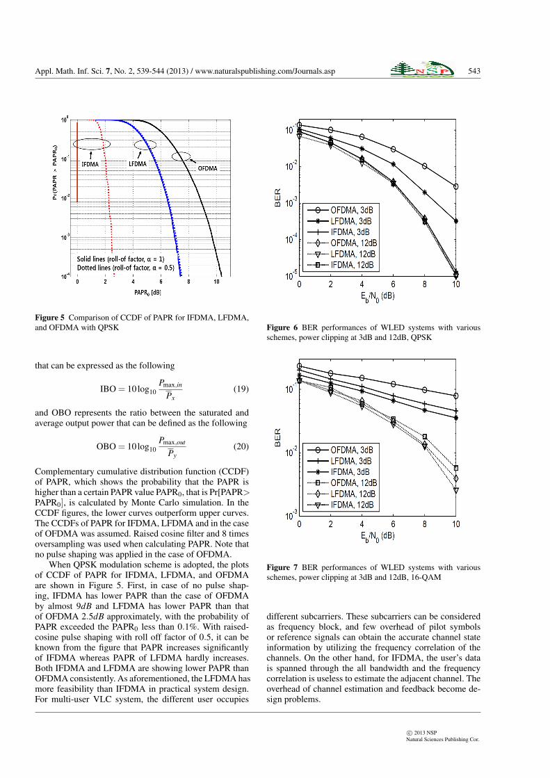
Figure 5 Comparison of CCDF of PAPR for IFDMA, LFDMA,and OFDMA with QPSK
that can be expressed as the following
IBO = 10log10Pmax,in
Px(19)
and OBO represents the ratio between the saturated andaverage output power that can be defined as the following
OBO = 10log10Pmax,out
Py(20)
Complementary cumulative distribution function (CCDF)of PAPR, which shows the probability that the PAPR ishigher than a certain PAPR value PAPR0, that is Pr[PAPR>PAPR0], is calculated by Monte Carlo simulation. In theCCDF figures, the lower curves outperform upper curves.The CCDFs of PAPR for IFDMA, LFDMA and in the caseof OFDMA was assumed. Raised cosine filter and 8 timesoversampling was used when calculating PAPR. Note thatno pulse shaping was applied in the case of OFDMA.
When QPSK modulation scheme is adopted, the plotsof CCDF of PAPR for IFDMA, LFDMA, and OFDMAare shown in Figure 5. First, in case of no pulse shap-ing, IFDMA has lower PAPR than the case of OFDMAby almost 9dB and LFDMA has lower PAPR than thatof OFDMA 2.5dB approximately, with the probability ofPAPR exceeded the PAPR0 less than 0.1%. With raised-cosine pulse shaping with roll off factor of 0.5, it can beknown from the figure that PAPR increases significantlyof IFDMA whereas PAPR of LFDMA hardly increases.Both IFDMA and LFDMA are showing lower PAPR thanOFDMA consistently. As aforementioned, the LFDMA hasmore feasibility than IFDMA in practical system design.For multi-user VLC system, the different user occupies
Figure 6 BER performances of WLED systems with variousschemes, power clipping at 3dB and 12dB, QPSK
Figure 7 BER performances of WLED systems with variousschemes, power clipping at 3dB and 12dB, 16-QAM
different subcarriers. These subcarriers can be consideredas frequency block, and few overhead of pilot symbolsor reference signals can obtain the accurate channel stateinformation by utilizing the frequency correlation of thechannels. On the other hand, for IFDMA, the user’s datais spanned through the all bandwidth and the frequencycorrelation is useless to estimate the adjacent channel. Theoverhead of channel estimation and feedback become de-sign problems.
c⃝ 2013 NSPNatural Sciences Publishing Cor.

544 Y.J. Kim, X. Li: A Low PAPR Visible Light Communication System...
Figure 6 and 7 show the BER performances of pro-posed schemes and VLC system employing OFDMA tech-nique. We plot the theoretical performance of both IFDMAand LFDMA system. Figure 6 shows the link level per-formances of WLED communication system with QPSKmodulation. The signal is clipped due to WLED device’scharacteristic. It is observed that when the clipping oc-curs at 12dB level above the normalized power, the perfor-mance degrades slightly because the probability of peakpower exceeds 12dB level is small. However, the perfor-mance degrades significantly when clipping occurs at 3dBlevel. Figure 7 shows the similar results while the digitalsignals are modulated by 16-QAM. The performance de-grades slightly when the clipping occurs at 12dB level andit degrades significantly when clipping occurs at 3dB level.On the other hand, all performances of 16-QAM degradedue to the power per bit degrades comparing to the systemwhich modulated by QPSK. This is because the 16-QAMis not constant modulation, and it introduces some level ofPAPR.
In the simulations above, the clippings generates bothin-band and out-band frequency components which takeeffects to the orthogonality between subcarriers, thereforethe BER performances degrade a lot. In any situation above,the WLED communication system with SC-FDMA tech-nique outperforms that with OFDMA.
5. Conclusions
A visible light wireless communication prototype has de-veloped. The transmission is based on the assumptions ofoptical Rayleigh fading channel and AWGN channel, theamplifier at the transmitter is assumed to be nonlinear. Wedemonstrated that the white LED based visible light datatransmission system employing the SC-FDMA multiplex-ing method, is indeed technically feasible. The low PAPRproperty of the SC-FDMA technique makes the LED basedVLC system to avoid nonlinear distortion which leads bet-ter performances than OFDMA-employed system in non-linear channel, and low peak power driving LED protectshuman’s eye.
Acknowledgement
This research was supported by Basic Research Programthrough the National Research Foundation of Korea (NRF)funded by the Ministry of Education, Science and Technol-ogy (2012R1A1B6002111).The authors are grateful to the anonymous referee for acareful checking of the details and for helpful commentsthat improved this paper.
References[1] T. Komine and M. Nakagawa, IEEE Transactions on Con-
sumer Electronics 50, 100-107 (2004).
[2] J.H. Kim, C.G. Lee and C.S. Park, Proc. International Societyfor Optical Engineering 6353, 635340 (2006).
[3] Y. Tanaka, T. Komine, S. Haruyama, and M. Nakagawa, Proc.12th IEEE ISPMR 2001 2, 81-85 (2001).
[4] M.Z. Afgani, H. Haas, H. Elgala, and D. Knipp, Proc. 2ndTRI-DENTCOM 2006, 129-134 (2006).
[5] H. Elgala, R. Mesleh, H. Haas, and B. Pricope, Proc. 65thIEEE VTC 2007 spring, 2185-2189 (2007).
[6] H.G Myung, J. Lim, and D.J. Goodman, IEEE VehicularTechnology Magazine 1, 30-38 (2006).
[7] H. Elgala, R. Mesleh, and H. Haas, IEEE WOCN09, 1-5(2009).
[8] T.S. Rappaport, Wireless Communications: Principles andPractice, Prentice Hall, (2002).
[9] H.G. Myung, J. Lim, and D.J. Goodman, Proc. IEEEPIMRC06, 1-5 (2006).
[10] C. Rapp, Proc. Second European Conference on SatelliteCommunications, 179-184 (1991).
Young-Ju Kim received thePh.D degree in Electrical En-gineering from Korea AdvancedInstitute of Science and Tech-nology, Republic of Korea, in2001. He has been with LG elec-tronics again in UMTS ResearchCenter, Republic of Korea, wherehe is a senior researcher from2001 to 2003. Since 2003, hehas been with the Departmentof Information and Communi-
cation Engineering at Chungbuk National University, Re-public of Korea, where he is now an Associate Professor.His research interests include LTE-Advanced standardiza-tion and distributed antenna system design.
Xun Li received the Ph.Ddegree in Information and Com-munication Engineering fromChungbuk National University,Cheongju, Republic of Korea,in 2013. Now, he is researcherin Research & Innovation Cen-ter, Alcatel-Lucent Shanghai Bell,Shanghai, China. His researchinterests are in the areas of mul-tiple antennas systems, OFDM,signal processing, etc. He is also
interested in next generation communication technique inLTE-Advanced standardization.
c⃝ 2013 NSPNatural Sciences Publishing Cor.


![PAPR analysis in Wavelet Packet Modulationmatthieugautier.free.fr/media/Gautier_ISCCSP_08.pdf · PAPR reduction techniques [2]-[5] have been proposed to reduce the PAPR problem in](https://img.dokumen.tips/doc/110x75/603d707e6c45f80b6138be06/papr-analysis-in-wavelet-packet-modul-papr-reduction-techniques-2-5-have-been.jpg)