Embed Size (px)
Citation preview

The University of Maine The University of Maine
DigitalCommons@UMaine DigitalCommons@UMaine
Electronic Theses and Dissertations Fogler Library
Spring 5-2020
A Linear Actuator/Spring Steel-Driven Glove for Assisting A Linear Actuator/Spring Steel-Driven Glove for Assisting
Individuals with Activities of Daily Living Individuals with Activities of Daily Living
Daniel Chizhik University of Maine, [email protected]
Follow this and additional works at: https://digitalcommons.library.umaine.edu/etd
Part of the Biomechanical Engineering Commons
Recommended Citation Recommended Citation Chizhik, Daniel, "A Linear Actuator/Spring Steel-Driven Glove for Assisting Individuals with Activities of Daily Living" (2020). Electronic Theses and Dissertations. 3167. https://digitalcommons.library.umaine.edu/etd/3167
This Open-Access Thesis is brought to you for free and open access by DigitalCommons@UMaine. It has been accepted for inclusion in Electronic Theses and Dissertations by an authorized administrator of DigitalCommons@UMaine. For more information, please contact [email protected].

A LINEAR ACTUATOR/SPRING STEEL-DRIVEN GLOVE FOR ASSISTING
INDIVIDUALS WITH ACTIVITIES OF DAILY LIVING
By
Daniel Chizhik
B.S. University of Maryland-Baltimore County, 2018
A THESIS
Submitted in Partial Fulfillment of the
Requirements for the Degree of
Master of Science
(in Mechanical Engineering)
The Graduate School
The University of Maine
May 2020
Advisory Committee:
Babak Hejrati, Assistant Professor of Mechanical Engineering, Advisor
Mohsen Shahinpoor, Professor of Mechanical Engineering
Andrew Goupee, Assistant Professor of Mechanical Engineering

A LINEAR ACTUATOR/SPRING STEEL-DRIVEN GLOVE FOR ASSISTING
INDIVIDUALS WITH ACTIVITIES OF DAILY LIVING
By Daniel Chizhik
Thesis Advisor: Dr. Babak Hejrati
An Abstract of the Thesis Presented
in Partial Fulfillment of the Requirements for the
Degree of Master of Science
(in Mechanical Engineering)
May 2020
Over three million people in the U.S. suffer from forearm and hand disabilities.
This can result from aging, neurological disorders (e.g., stroke), chronic disease (e.g.,
arthritis), and injuries. Injuries to hands comprise one-third of all work-related injuries
worldwide. This can lead to difficulties with activities of daily living (ADL), where one
needs to grasp, lift, and release objects in the household. There is a rise in demand for
assistive orthoses and gloves that can allow many people to regain their
grasping/releasing ability and, thereby, their independence. The main contribution of
this thesis is developing an assistive glove with the actuating mechanism comprised of
linear actuators and strips of spring steel to enable bidirectional motion of users' fingers
during ADL. The target group of people to use this proposed actuation system was
chosen to those who had only diminished hand grasping capabilities. There are already
many different gloves in the market. Each one uses different methods of actuation and
force transmission, as well as different control methods. These gloves were analyzed by
looking at their actuation mechanisms, control systems, and the benefits and downfalls
of each one.

Vigorous testing was conducted to choose the most effective components for the
actuating mechanism. Then, an assistive glove was fabricated which included a control
system box that could be easily worn on the forearm of the user. Tests were conducted
on the glove to test its effectiveness when the user’s hand was completely passive using
four to six participants. Motion capture, force, and electromyography (EMG) data were
collected and from those, range of finger motion, maximum grasping capabilities,
maximum force generation, and muscle activity were analyzed. The glove was shown to
actuate the fingers enough to grasp objects with different sizes ranging in diameter from
40mm to 80mm, with maximum possible weight able to be picked up being around
1000g for the larger sizes. The glove could generate 4N-5N to the index and middle
fingers and 10N to the thumb. EMG analysis showed that using the glove to pick up
heavy objects caused a decrease in muscle activity of up to 80%. From this analysis, it
was shown that the glove has potential to assist with ADL and would provide greater
independence for those with diminished hand grasping abilities.

ii
TABLE OF CONTENTS
LIST OF TABLES ............................................................................................................................. iv
LIST OF FIGURES ........................................................................................................................... v
Chapters
1 INTRODUCTION ....................................................................................................................... 1
1.1 Current Actuation Designs .............................................................................................. 1
1.1.1 Methods of Actuation ......................................................................................... 1
1.1.2 Force Transmission ........................................................................................... 2
1.1.3 Control System Design ...................................................................................... 4
1.2 Sensors ........................................................................................................................... 6
1.2.1 EMG .................................................................................................................. 6
1.2.2 Force Sensor ..................................................................................................... 7
1.2.3 Flex Sensor ....................................................................................................... 7
1.2.4 Distance Sensor ................................................................................................ 8
1.3 Biomechanics and Anatomy of the Human Hand and Forearm ..................................... 9
1.3.1 Anatomical Directions ...................................................................................... 10
1.3.2 Bones and Joints ............................................................................................. 10
1.3.3 Muscles ........................................................................................................... 11
2 PLAN OF ACTION FOR THE DESIGN OF THE GLOVE ....................................................... 13
2.1 Glove Objectives ........................................................................................................... 13
2.2 Glove Part Selection ..................................................................................................... 15
2.3 Finalized Glove Design Feasibility Testing ................................................................... 17
3 EXPERIMENTAL PROCEDURE ............................................................................................ 18
3.1 Actuation Mechanism Feasibility Test ........................................................................... 18
3.2 Assessment of the Assembled Glove ........................................................................... 21

iii
3.2.1 Assembled Glove Motion Capture .................................................................. 21
3.2.2 Assembled Glove Grasping and Lifting Tests ................................................. 22
3.2.3 Assembled Glove Force Generation Test ....................................................... 23
3.2.4 Assembled Glove Muscle Activity Test ........................................................... 24
4 RESULTS ................................................................................................................................ 29
4.1 Actuation Mechanism Feasibility Results ...................................................................... 29
4.1.1 Steel Thickness ............................................................................................... 31
4.1.2 Actuator Type .................................................................................................. 33
4.1.3 Other Effects ................................................................................................... 35
4.2 Resulting Assistive Glove Design ................................................................................. 37
4.3 Assessment of the Assembled Glove’s Performance ................................................... 42
4.3.1 Glove Assembly .............................................................................................. 42
4.3.2 Assembled Glove Motion Capture Results ..................................................... 43
4.3.3 Assembled Glove Grasping and Lifting Results .............................................. 47
4.3.4 Assembled Glove Force Generation Results .................................................. 49
4.3.5 Assembled Glove Muscle Activity Analysis ..................................................... 51
5 CONCLUSION ........................................................................................................................ 54
5.1 Possibilities for Future Investigation ............................................................................. 55
REFERENCES ............................................................................................................................... 57
APPENDIX ..................................................................................................................................... 62
BIOGRAPHY OF THE AUTHOR ................................................................................................... 65

iv
LIST OF TABLES
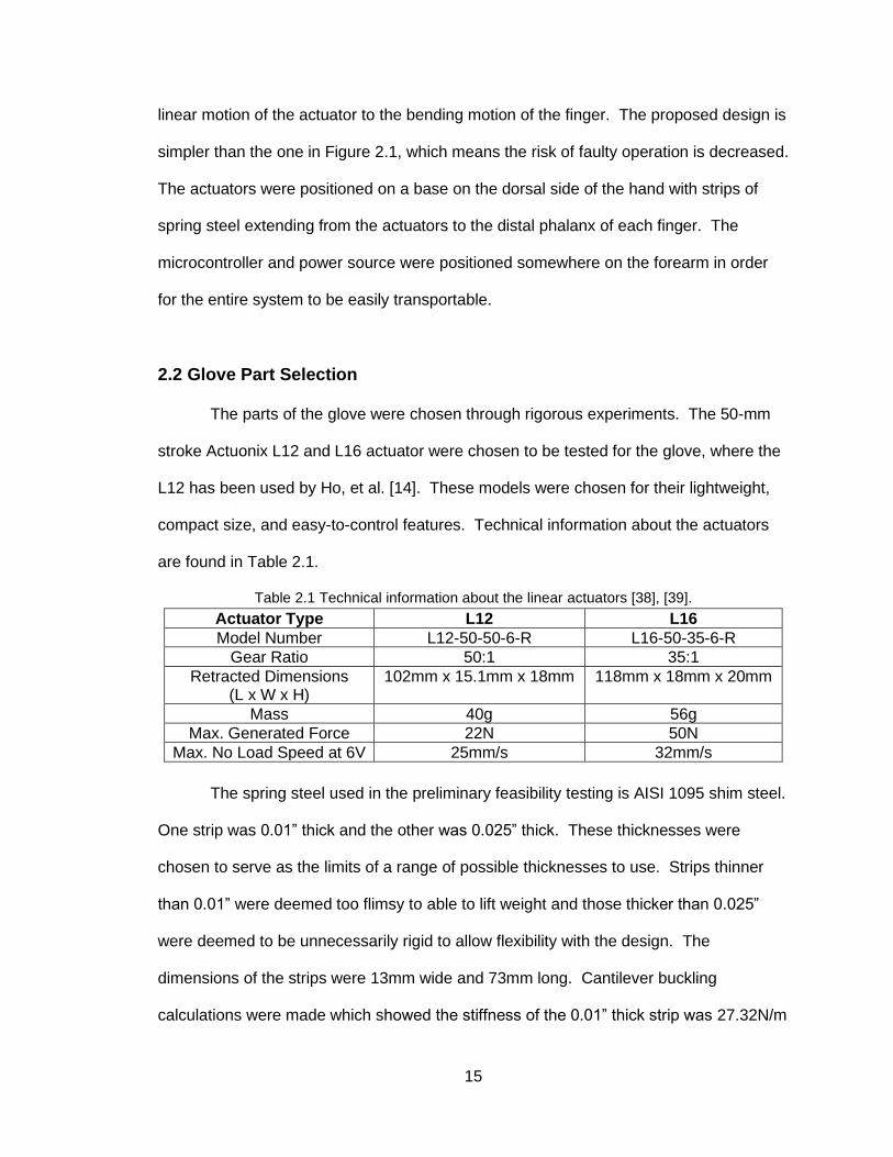
Table 2.1 Technical information about the linear actuators [38], [39] ..................................... 15
Table 3.1 DH Parameters. Lengths are in mm; angles are in radians (* indicates a
variable) ................................................................................................................... 21
Table 4.1 Pairwise comparison of different masses affecting the dependent variables
(* indicates a significant difference between pairs) ................................................. 36
Table 4.2 Cost breakdown of the assistive glove. (~ indicates an estimated cost as it
depends on where the parts are printed) ................................................................ 42
Table 4.3 Index finger lengths of each subject and their respective glove sizes .................... 44
Table 4.4 The average angles of the live index finger and gloved index finger at
maximum flexion along with their respective standard deviations .......................... 47
Table 4.5 Average percent differences, standard deviation, and pairwise comparison of
the glove affecting muscle activity (* indicates a significant difference
between the pairs) ................................................................................................... 53

v
LIST OF FIGURES
Figure 1.1 Examples of different actuators used in orthosis and glove design: (a) DC
motors [4], (b) a linear actuator [5], and (c) pneumatics [6] ....................................... 2
Figure 1.2 Examples of a cable-driven mechanism by (a) In, et al. [10], (b) Nycz, et al.
[11], and (c) Biggar, et al. [12] .................................................................................... 2
Figure 1.3 Examples of high- and low-profile rigid linkages used in orthoses that were
designed by (a) Wang, et al. [16], (b) Hasegawa, et al. [17], and (c) Ben-Tzvi,
et al. [18] ..................................................................................................................... 3
Figure 1.4 Examples of soft robotic gloves by (a) Borboni, et al. [23], (b) Polygerinos,
et al. [22], and (c) Gerez, et al. [24]. ........................................................................... 3
Figure 1.5 Examples of wearable control systems mounted on the (a) upper arm [3],
(b) wrist [8], and (c) again on the upper arm [25] ....................................................... 4
Figure 1.6 Gloves designed by (a) In, et al. [26] and (b) Polygerinos, et al. [27] being
controlled with a GUI .................................................................................................. 4
Figure 1.7 (a) A low-profile cable-driven glove and (b) its control system with attached
actuators [13] .............................................................................................................. 5
Figure 1.8 (a) A glove that uses a water pump to actuate the fingers and (b) its wearable
control system [20] ..................................................................................................... 5
Figure 1.9 (a) A control box with button control on its top. The microcontroller and pump
parts are housed inside. (b) A glove with its control box (center) and GUI
(left) [6], [28]. .............................................................................................................. 6
Figure 1.10 Examples of (a) a wet EMG and (b) a dry one ........................................................... 7
Figure 1.11 Examples of (a) an FSR, (b) a capacitive force sensor, and (c) a
load cell [29]-[31] ........................................................................................................ 7
Figure 1.12 (a) A flex sensor and (b) a glove that uses one in its control system [1] .................... 8
Figure 1.13 Examples of (a) an ultrasonic sensor and (b) an IR sensor. (c) shows an
assembled glove with the IR sensor located on the palmar side
of the wrist [1] ............................................................................................................. 9
Figure 1.14 A hand (a) grasping a coffee mug and (b) pinch gripping a pen ................................ 9
Figure 1.15 Anatomical directions of the hand and forearm ........................................................ 10
Figure 1.16 Joints of the hand ..................................................................................................... 11
Figure 1.17 Posterior views of the muscles that control finger movement (a) Flexor
digitorum superficialis, (b) flexor digitorum profundus, (c) extensor indicis,
(d) extensor digiti minimi, and (e) extensor digitorum [37] ....................................... 12

vi
Figure 1.18 Posterior views of the muscles that control thumb movement. (a) Flexor
pollicis longus, (b) abductor pollicis longus, (c) extensor pollicis brevis, and
(d) extensor pollicis longus [37]. ............................................................................... 12
Figure 2.1 (a-b) The linear actuator-spring steel driven glove and (c) an up-close look
at its actuating mechanism [38], [39] ........................................................................ 14
Figure 2.2 The designed one-finger experimental setup ........................................................... 16
Figure 3.1 (a-b) Incremental extension of the linear actuator. (b) The placement of
tracking markers in Tracker ...................................................................................... 19
Figure 3.2 Kinematic diagram of the finger ................................................................................ 20
Figure 3.3 A diagram of the DH frames attached to the actuation mechanism in a
zero-angle position ................................................................................................... 20
Figure 3.4 Examples of common household objects. (a) a jar of pasta sauce, a water
bottle, and a speaker. (b) a tube of lotion ................................................................ 22
Figure 3.5 The container used for testing (far right) and the different caps. From left to
right, the cap diameters are 40mm, 50mm, 60mm, 70mm, and 80mm. The
container is also 80mm in diameter .......................................................................... 22
Figure 3.6 The force testing setup with the FSR attached to the side of the cylinder.
The microcontroller is on the bottom left .................................................................. 23
Figure 3.7 Calibration curve for the FSR used in the experiment ............................................. 24
Figure 3.8 The muscles used in the experiments. (a) ECRL, (b) FCR, and (c) FDS [47] ........ 25
Figure 3.9 Anterior (a,d), lateral (b,e), and posterior (c,f) views of extensor and flexor
muscles. (a)-(c) show the finger extensor and flexor muscles overlapping
over each other and (d)-(f) show the muscles that the EMGs were positioned
over [37]. ................................................................................................................... 26
Figure 3.10 (a) The collected MVC signal of the extensor carpi radialis longus. (b) shows
the muscle from the anterior side and (c) shows it from the lateral side [48] ........... 27
Figure 3.11 Plot of filtered muscle signal (a) before resting signal is subtracted, and
(b) after. The shaded areas are what were integrated. ........................................... 28
Figure 4.1 Graphical representation of the workspace of the actuation mechanism
(blue “o”) and the fingertip coordinates (red “x”). The left y-axis shows the
shim’s height from the forward kinematics analysis, while the right y-axis
shows the height of the fingertip from motion capture analysis ............................... 30
Figure 4.2 Finger joints’ heights when using the L12 actuator with (a) no load, (b) 100g,
(c) 300g, and (d) 400g. Solid lines represent the 0.010” strip while the
dashed lines represent the 0.025” strip. The vertical dashed lines indicate
the stroke increments. The profiles for different masses using the L16
actuator follow similar patterns ................................................................................. 31

vii
Figure 4.3 Joint angles of the model finger under the L12 actuator, 0.010” strip, while
lifting a 300g mass. Solid lines represent the 0.010” strip and dashed lines
represent the 0.025” strip. The vertical dashed lines indicate the stroke
increments. Similar behavior was observed when using the L16 actuator,
or when using heavier masses ................................................................................. 32
Figure 4.4 Bar plots show the means and standard errors of the fingertip height at the
actuators’ full extension for different (a) strip thicknesses and (b) masses
(* indicates a significant difference between the conditions) ................................... 33
Figure 4.5 Bar plots show the means and standard errors of the extension and
retraction velocities of both actuators and strips tested by different masses.
The (a) L12 actuator with 0.010” strip, (b) L16 actuator with 0.010” strip,
(c) L12 actuator with 0.025” strip, and (d) L16 actuator with 0.025” strip ................. 34
Figure 4.6 Bar plots show the means and standard errors of the extension velocities.
(a) Extension velocity and (b) retraction velocity for different actuator types
and masses. The * indicates a significant difference between the conditions ....... 35
Figure 4.7 Bar plots show the mean and standard errors of the tip height for both
actuators and strips tested by different masses. The (a) L12 actuator with
0.010” strip, (b) L16 actuator with 0.010” strip, (c) L12 actuator with 0.025”
strip, and (d) L16 actuator with 0.025” strip .............................................................. 36
Figure 4.8 The assembled assistive glove ................................................................................ 37
Figure 4.9 The three different gloves available for users. (a) medium, (b) large, and
(c) extra-large. The large glove has the actuating mechanism connected to it ...... 38
Figure 4.10 (a) The control system hardware inside the housing and (b) the battery
connected to the PowerBoost. (c) and (d) show the two different control
mechanisms: a flex sensor inside a sleeve on the pinky finger and a
control box ................................................................................................................ 40
Figure 4.11 The fully assembled glove worn on the right hand with the flex sensor control
option Implemented. (a) anterior view and (b) posterior view ................................. 41
Figure 4.12 The steel strip for the thumb being fixed to the thimble ........................................... 43
Figure 4.13 Screenshots of the Tracker software for (a) a free-moving finger, (b) a
cylinder, and (c) a finger freely actuated by the glove .............................................. 44
Figure 4.14 Finger joint motion profiles of each subject while grasping a 40mm cylinder,
80mm cylinder, and nothing. The final plot (F) has the motion profile of
Subject F grasping a 70mm cylinder instead because that was the largest
object he could grasp ............................................................................................... 45
Figure 4.15 The finger joint motion profiles of (a) a 40mm cylinder, (b) an 80mm cylinder,
and (c) free movement when Subject B is wearing the glove and when he
isn’t. The point in the lower left-hand part of each plot is the stationary
MCP joint and the rightmost profiles are those of the fingertip ................................ 46

viii
Figure 4.16 Joint angles of the index finger when the glove is not used (blue) and when
it is used (red) ........................................................................................................... 47
Figure 4.17 The experiment being conducted with a subject attempting to grasp (a) a
70mm cylinder and (b) a 40mm cylinder .................................................................. 48
Figure 4.18 Liftable weight in relation to the size of the cylinder ................................................. 49
Figure 4.19 A subject grasping the 80mm cylinder with the FSR collecting force data from
the middle finger ....................................................................................................... 50
Figure 4.20 Force generated by each digit on the cylinder ......................................................... 50
Figure 4.21 The EMG acquisition software running on the computer and the subject
getting ready to lift the cylinder ................................................................................. 51
Figure 4.22 Muscle activity of the FDS of Subject B (a) when the glove was not used and
the hand was active, and (b) when the glove was used and the hand
was passive .............................................................................................................. 52
Figure 4.23 (a) Average muscle activity while the cylinder was manipulated. (b) Percent
decrease in muscle activity between the case of lifting an object with and
without the glove ....................................................................................................... 52
Figure A.1 Design iterations of the dorsal actuator mount ......................................................... 62
Figure A.2 Design iterations of the thumb actuator mount ........................................................ 62
Figure A.3 Design iterations of the thimbles. Model v3 was used in the initial
feasibility test ............................................................................................................ 63
Figure A.4 Design iterations of the control system box ............................................................. 63
Figure A.5 Design iterations of the spring steel strips ............................................................... 64

1
CHAPTER 1
INTRODUCTION
Over three million people in the U.S. suffer from forearm and hand disabilities.
This can result from aging, neurological disorders (e.g., stroke), chronic disease (e.g.,
arthritis), and injuries. Injuries to hands comprise one-third of all work-related injuries
worldwide [1]. This can lead to difficulties with activities of daily living (ADL), where one
needs to grasp, lift, and release objects in the household. There is a rise in demand for
assistive orthoses and gloves that can allow many people to regain their
grasping/releasing ability and, thereby, their independence [2], [3].
The following sections in this chapter will go over the current advances in
orthosis design. Various actuation and sensing mechanisms will be discussed in this
chapter. Different control strategies will be reviewed, and a brief explanation of the
biomechanics of a human hand and its anatomy will also be covered.
1.1 Current Actuation Designs
1.1.1 Methods of Actuation
Robotic gloves are comprised of three parts: actuators, a method by which to
transmit the force from the actuator to the fingers, and a control system. The most
commonly used actuators are DC motors, servo motors (rotary or linear), and
pneumatics. Examples of orthoses and gloves using the different actuators are shown in
Figure 1.1. Figure 1.1(a) shows an orthosis that uses DC motors to actuate rigid
linkages, whereas Figure 1.1(b) utilizes a linear actuator to move cables. Figure 1.1(c)
uses pneumatic actuators to send air through tubes along the fingers to actuate them.

2
Figure 1.1 Examples of different actuators used in orthosis and glove design: (a) DC
motors [4], (b) a linear actuator [5], and (c) pneumatics [6].
1.1.2 Force Transmission
The most commonly used forms of force transmission from the actuators to the
fingers are with cables, rigid linkages, or tubing. Each method of force transmission has
its advantages and disadvantages.
Cable-driven gloves can have a very low profile on the hand and very effective in
manipulating a wide variety of objects [1], [7]-[9]. They allow the user to have as much
of a range of motion in the hand as a healthy person. Depending on how they’re
designed, these gloves may provide unidirectional or bidirectional movement of the
fingers. However, the cables are at risk of getting jammed in the cable guide, which
leads to insufficient force transmission to the fingertips. Figure 1.2 shows different
examples of cable-drive gloves.
Figure 1.2 Examples of a cable-driven mechanism by (a) In, et al. [10],
(b) Nycz, et al. [11], and (c) Biggar, et al. [12].
Rigid linkages are another effective method for actuating each finger. These
methods have been used designs by Cui, et al. [13], Ho, et al. [14], and Arata, et al. [15],
to name a few. However, if the linkages are too big, which they are in many cases, they
(a) (b) (c)
(a) (b) (c)

3
can restrict the user’s ability to grasp certain objects such as things with handles (e.g.,
mugs, kettles, and coffee pots). Having linkages for each finger also increases the
complexity of the orthosis and has an increased risk of something going wrong during
operation such as the linkage joints misaligning. Figure 1.3 shows examples of different
rigid linkage designs.
Figure 1.3 Examples of high- and low-profile rigid linkages used in orthoses that were designed
by (a) Wang, et al. [16], (b) Hasegawa, et al. [17], and (c) Ben-Tzvi, et al. [18].
Gloves that use pneumatics require tubing to transfer force to the fingertips, such
as those made by Yap, et al. [19], Polygerinos, et al. [20], and Connelly, et al. [21].
These tubes are usually used to inflate special pockets that sit along the fingers. As
fluids are pumped into them, the inflated pockets curl the fingers. This is a very effective
and low-profile way of actuating hands. Unfortunately, the air compressors and fluid
pumps used in these designs can be bulky, heavy, and noisy, restricting the portability of
the glove. Figure 1.4 shows different examples of gloves that implement pneumatics to
actuate the fingers.
Figure 1.4 Examples of soft robotic gloves by (a) Borboni, et al. [22],
(b) Polygerinos, et al. [23], and (c) Tadano, et al. [24].
(a) (b) (c)
(a) (b) (c)

4
1.1.3 Control System Design
As previously stated, size matters when it comes to the design of an glove, and
that does not change for the control system hardware. A compact control box, such as
the ones in Figure 1.5, will allow the user to use the glove more easily and in a greater
number of places.
Figure 1.5 Examples of wearable control systems mounted on the (a) upper
arm [3], (b) wrist [8], and (c) again on the upper arm [25].
Control systems are made up of a power source, some sort of circuit board, such
as a microcontroller or even a graphical user interface (GUI), and any other electrical
components associated with controlling the gloves’ actuation, such as sensors. If the
control system uses a GUI, such as those in Figure 1.6, the glove is usually intended for
feasibility testing or rehabilitation and not everyday use.
Figure 1.6 Gloves designed by (a) In, et al. [26] and (b) Polygerinos,
et al. [27] being controlled with a GUI.
Depending on the overall design of the glove, the actuators may be housed with
the control system. The cable-driven glove by Cui, et al. shown in Figure 1.7 is low-
profile and very effective for ADL [13]. However, the control system and actuators are
not wearable, limiting the portability of the device.
(a) (b) (c)
(a) (b)

5
Figure 1.7 (a) A low-profile cable-driven glove and (b) its control system
with attached actuators [13].
Similarly, gloves with air compressors and hydraulic pumps suffer from the lack
of portability. The control system itself may be small, but the air pump and its additional
components are housed with it as shown in Figure 1.8(b). The entire system has been
designed to be worn on the waist but would still be difficult to don without assistance.
Figure 1.8 (a) A glove that uses a water pump to actuate the fingers
and (b) its wearable control system [20].
If the control system does not use any sensors on the glove, buttons located on
the control box may be used, as shown in Figure 1.9. It is important to note that these
gloves are mainly intended for rehabilitation, so it is not critical for the control box to be
easily transportable. However, the fact remains that a compressed air-based control
system is not the best option for having a lightweight and portable glove.
(a) (b)
(a) (b)

6
Figure 1.9 (a) A control box with button control on its top. The microcontroller and pump parts
are housed inside. (b) A glove with its control box (center) and GUI (left) [6], [28].
1.2 Sensors
Sensors are used in different ways in a control system. They may be used as
inputs to actuate the glove or feedback sensors. Electromyography (EMG), force, flex,
and distance sensors are such examples.
1.2.1 EMG
EMG sensors are used to measure the muscle activity as a means of controlling
an glove. The higher the voltage measured, the higher the muscle activity. The most
common type of EMG used in control systems are surface EMGs (EMG). These sit on
one’s skin using an adhesive. They use either an electroconductive adhesive
membrane (called wet EMG) or metal contacts (called dry EMG) to detect the muscle
activity.
(b)
(a)

7
Figure 1.10 Examples of (a) a wet EMG and (b) a dry one.
1.2.2 Force Sensor
Two kinds of force sensors are typically used in control systems: a resistance-
based sensor called a force sensitive resistor (FSR), or a capacitive-based sensor.
These sensors measure the change in either resistance or capacitance. As the applied
force increases, the value the sensors read increases. Another type of force sensor,
called a load cell, may also be used, but they are usually only used to test the glove and
not control it. The following figure shows examples of each force sensor.
Figure 1.11 Examples of (a) an FSR, (b) a capacitive force sensor,
and (c) a load cell [29]-[31].
1.2.3 Flex Sensor
Flex sensors act the same way as FSRs in the sense that they read the change
in resistance, this time by the sensor’s bending. As the sensor bends more, the
resistance increases. Because flex sensors are long and thin, they can be attached to
one or more fingers in a glove to independently control them. Figure 1.12 shows an
(b) (a)
(b)
(c)
(a)

8
example of a flex sensor and a glove design by Popov, et al. that uses one its control
system [1].
Figure 1.12 (a) A flex sensor and (b) a glove that uses them in its control system [1].
Flex sensors may also be calibrated like FSRs to measure the angle of
something bending, like a finger joint. This is done by collecting the analog output signal
of the sensor when it is bent at different angles. The data is then analyzed the same
way as the FSR data to find an equation that relates analog signal to angle
measurement.
1.2.4 Distance Sensor
A distance sensor may be attached to the palmar area of a glove to detect when
it is close enough to an object to grasp it. One such sensor uses ultrasound to detect a
change in distance, but these are rather large. A more low-profile sensor is an infrared
(IR) sensor. This one uses a small infrared light to detect a change in distance. Figure
1.13 shows examples of (a) an ultrasonic sensor, (b) an IR sensor, and (c) a glove that
uses a distance sensor in its control system.
(a)
(b)

9
Figure 1.13 Examples of (a) an ultrasonic sensor and (b) an IR sensor. (c) shows an assembled
glove with IR sensor located on the palmar side of the wrist [1].
1.3 Biomechanics and Anatomy of the Human Hand and Forearm
From a mechanical standpoint, the anatomy of the hand is the most complex part
of the human body. It is our main way of interacting with the environment, and its
dexterity allows us to manipulate different tools and objects. Positioning the fingers
differently allows us to grasp large objects and perform a pinch grip on smaller objects.
Diminished grip strength can be caused by illness, such as stroke or arthritis, or injury,
such as a spinal injury.
Figure 1.14 A hand (a) grasping a coffee mug and (b) pinch gripping a pen.
(b) (c)
(a)
(b) (a)

10
1.3.1 Anatomical Directions
Directions are important when discussing any part of human anatomy. The
terms vary depending on what part of the body is being referred. For the hand, the
following directional terms are used [32]. Moving from the wrist to the fingers is called
the distal direction. Moving vice versa is called the proximal direction. The direction
towards the thumb from the imaginary midline of the hand is called lateral and the
direction towards the pinky finger from the midline is called medial. The palm’s side of
the hand is called the palmar side and the opposite side is called the dorsal side.
Moving towards the palm is called the anterior direction and moving towards the dorsal
side is called the posterior direction.
Figure 1.15 Anatomical directions of the hand and forearm.
1.3.2 Bones and Joints
Each digit in the hand is comprised of three joints [33], as shown in Figure 1.16.
The joint closest to the palm is called the metacarpophalangeal joint (MCP). The next
joint is called the proximal interphalangeal joint (PIP). The last one is called the distal
interphalangeal joint (DIP). The joints are a bit different for the thumb. The farthest joint
is just called the interphalangeal joint, but for simplicity, it shall be called the PIP here.

11
The next joint closer to the palm is the MCP. The joint closest to the wrist is called the
carpometacarpal joint (CMC).
Figure 1.16 Joints of the hand.
1.3.3 Muscles
The muscles that control the movement of the fingers are located in the forearm.
According to W. D. Gardner’s Structure of the Human Body, there are five muscles that
do this [34]. They are the flexor digitorum superficialis, flexor digitorum profundus,
extensor digitorum, extensor digiti minimi, and extensor indicis. As the names imply, the
first two muscles control finger flexion and the last three control finger extension.
Figures 1.17(a-b) show the flexor muscles and Figures 1.17(c-e) show the extensor
muscles.

12
Figure 1.17 Posterior views of the muscles that control finger movement. (a) Flexor digitorum
superficialis, (b) flexor digitorum profundus, (c) extensor indicis, (d) extensor digiti minimi,
and (e) extensor digitorum [35].
An additional four muscles, shown in Figure 1.18, are used for controlling thumb flexion
and extension. They are the flexor pollicis longus, abductor pollicis longus, extensor
pollicis brevis, and extensor pollicis longus.
Figure 1.18 Posterior views of the muscles that control thumb movement. (a) Flexor pollicis
longus, (b) abductor pollicis longus, (c) extensor pollicis brevis,
and (d) extensor pollicis longus [35].

13
CHAPTER 2
PLAN OF ACTION FOR THE DESIGN OF THE GLOVE
The research conducted on different gloves yielded many different designs, each
with their merits and downsides. In order to design a unique glove without any of the
possible issues mentioned in the previous chapter, a different approach had to be taken.
This chapter will discuss what the glove should be able to do, how the different parts of
the glove will be chosen, and how the final design will be tested.
2.1 Glove Objectives
The goal of this research is to design a new glove that performs as well as the
current designs already conceived of without any of the potential flaws. It should be
intended for people who need assistance grasping household items. The glove will not
be intended to fully replace a person’s grasping capabilities.
Many gloves only actuated the index and middle fingers and the thumb while still
transmitting enough force to assist with activities of daily living (ADL) [10], [25], [26].
Therefore, the new glove would also actuate these three digits. The proposed actuation
mechanism design follows the idea of using spring steel for transferring force to the
fingertips, as found in a number of papers [15], [36], [37].

14
Figure 2.1 (a-b) The linear actuator-spring steel driven glove and (c) an up-close look at
the actuating mechanism [36], [37].
As shown in Figure 2.1, this spring steel design was able to mimic the natural
curling motion of the hand and was able to transmit 3N of force to each finger. The three
layers of steel made the system act like a Bowden cable so that it could accommodate
compression. Furthermore, it had no potential risks associated with cable-driven or rigid
linkage force transmission methods. Investigation into this specific force transmission
method had been done prior to this glove, so incorporating spring steel in this thesis
seemed like an opportune way to further research its potential applications.
It has been noted that the grasping forces needed to manipulate objects in ADL
are typically within the range of 10N-15N [1], [18], [20], [22]. The goal of this glove is to
generate 3N-5N of force for each finger using this linear actuator/spring steel actuation
system so that up to 15N of grasping force may be generated by using multiple actuators
in the glove. Another goal of the proposed design would be to actuate the index and
middle fingers and the thumb to enable both grasping and pinching tasks. This design
can mitigate the issues of joint misalignment and cable management by directly moving
the fingertip to enable grasping. Bidirectionality, or having the actuation mechanism
both flex and extend the fingers, is another goal the glove should meet.
The design in Figure 2.1 uses three layers of spring steel to enable curling of a
finger and transmit force to the fingertip. The proposed design in this thesis used a
single strip of spring steel to transmit force directly to the fingertip by converting the
(b) (a) (c)
15
linear motion of the actuator to the bending motion of the finger. The proposed design is
simpler than the one in Figure 2.1, which means the risk of faulty operation is decreased.
The actuators were positioned on a base on the dorsal side of the hand with strips of
spring steel extending from the actuators to the distal phalanx of each finger. The
microcontroller and power source were positioned somewhere on the forearm in order
for the entire system to be easily transportable.
2.2 Glove Part Selection
The parts of the glove were chosen through rigorous experiments. The 50-mm
stroke Actuonix L12 and L16 actuator were chosen to be tested for the glove, where the
L12 has been used by Ho, et al. [14]. These models were chosen for their lightweight,
compact size, and easy-to-control features. Technical information about the actuators
are found in Table 2.1.
Table 2.1 Technical information about the linear actuators [38], [39].
Actuator Type L12 L16
Model Number L12-50-50-6-R L16-50-35-6-R
Gear Ratio 50:1 35:1
Retracted Dimensions (L x W x H)
102mm x 15.1mm x 18mm 118mm x 18mm x 20mm
Mass 40g 56g
Max. Generated Force 22N 50N
Max. No Load Speed at 6V 25mm/s 32mm/s
The spring steel used in the preliminary feasibility testing is AISI 1095 shim steel.
One strip was 0.01” thick and the other was 0.025” thick. These thicknesses were
chosen to serve as the limits of a range of possible thicknesses to use. Strips thinner
than 0.01” were deemed too flimsy to able to lift weight and those thicker than 0.025”
were deemed to be unnecessarily rigid to allow flexibility with the design. The
dimensions of the strips were 13mm wide and 73mm long. Cantilever buckling
calculations were made which showed the stiffness of the 0.01” thick strip was 27.32N/m

16
and the stiffness of the 0.025” strip was 427.35N/m. This indicates that the thinner strip
might not be as effective as the thicker one in actuating the finger.
The actuators and steel strips were tested using an experimental setup
consisting of a 3D-printed mounting structure and model finger, the actuating system,
and a hanging weight to evaluate the actuators’ generated forces and motions. This
setup enabled the quantification of performance of the actuators and strips rather than
the user.
A 3D-printed thimble was also fabricated and positioned on the dorsal side of the
distal phalanx to secure the steel strip onto the finger. The model finger simulated a
user’s passive finger for which the actuating system would provide full assistance.
Although the model finger did not behave like a natural finger whose distal phalanx
movement relies on the movement of the intermediate phalanx, it could still give an
approximation of how an actual finger would behave with this system in place. The
entire setup was constructed such that the model finger would curl upwards to lift various
weights, as shown in Figure 2.2. The actuators would be controlled with an Arduino Uno
microcontroller and powered by a 9V battery.
Figure 2.2 The designed one-finger experimental setup.

17
2.3 Finalized Glove Design Feasibility Testing
Once the glove has been fully assembled, further experiments were conducted to
test the feasibility of the glove with human subjects, both healthy young adults and older
adults. It has been shown that older people have a weaker hand grip strength, meaning
they have to exert more energy during ADL than healthy people [40]. This is reflected in
their muscle activity [41]. For this reason, muscle activity was measured in the human
subjects to see if there was a noticeable change in the activity when the glove was being
used to manipulate different sized and weighted objects versus when the subjects used
solely their own abilities to perform the same tasks. Grasping force generated by the
glove was also measured. Adjustments to the design of the assistive glove were made
following analysis of the collected data and further experiments may be conducted.

18
CHAPTER 3
EXPERIMENTAL PROCEDURE
In order to prove the effectiveness of the designed glove, numerous tests had to
be conducted. This chapter will discuss the feasibility experiments done for the
actuating mechanism followed by the tests done on the fully assembled glove. The tests
consisted of motion capture while attempting to grasp different sized objects,
determining how much users are able to pick up with the glove depending on the size of
the objects, force generation capabilities of the glove, and muscle activity analysis while
the glove is being used.
3.1 Actuation Mechanism Feasibility Test
The Arduino microcontroller was programmed to extend the linear actuator in
four quarter-stroke increments, 12.5mm, 25mm, 37.5mm, and 50mm, and retract it in the
same way. This allowed for better analysis of the model finger’s movement. The
actuating system in Figure 2.2 was tested by adding hanging masses to the end of the
finger with increments of 100g. Each mass was tested five times. Motion data in the
form of x- and y-coordinates of the PIP and DIP joints, and the fingertip was then
collected using Tracker Video Analysis software [42]. The MCP joint was stationary and
served as the origin. Screenshots showing the different increments of the actuator
extension with the tracking markers on each joint can be shown in Figure 3.1. This data
was then exported into MATLAB to calculate the three joint angles.

19
Figure 3.1 (a-b) Incremental extension of the linear actuator. (b) The placement
of tracking markers in Tracker.
Using the joints’ coordinates, vectors were formed between phalangeal joints as
represented in Equations (1) – (3):
𝐥MCP = [
𝑃𝐼𝑃x
𝑃𝐼𝑃y] (1)
𝐥PIP = [
𝐷𝐼𝑃x − 𝑃𝐼𝑃x
𝐷𝐼𝑃y − 𝑃𝐼𝑃y] (2)
𝐥DIP = [
𝑇𝑖𝑝x − 𝐷𝐼𝑃x
𝑇𝑖𝑝y − 𝐷𝐼𝑃y] (3)
where (𝑃𝐼𝑃x, 𝑃𝐼𝑃y), (𝐷𝐼𝑃x, 𝐷𝐼𝑃y), and (𝑇𝑖𝑝x, 𝑇𝑖𝑝y) are the coordinates of the points used
to calculate the segment vectors of 𝐥MCP, 𝐥PIP, and 𝐥DIP as shown in Figure 3.2. The
finger’s joint angles were calculated as shown in Equations (4) and (5) for 𝜃MCP, where
the rest of angles were calculated in the same manner.
cos(𝜃MCP) =
𝐥MCP ∙ 𝐥PIP
(‖𝐥MCP‖)(‖𝐥PIP‖) (4)
𝜃MCP = ±2 tan−1 (√1 − cos(𝜃MCP)
1 + cos(𝜃MCP)) (5)
(a) (b)

20
Figure 3.2 Kinematic diagram of the finger.
Figure 3.3 shows a diagram of the Denavit-Hartenberg (DH) frames attached to the
actuating mechanism in its “zero-angle position,” where the mechanism consists of a
prismatic and a rotary joint. The diagram is used to compare the movement of the
fingertip with the movement of the actuation mechanism. The forward kinematics of the
mechanism were evaluated using Equations (6) and (7).
Figure 3.3 A diagram of the DH frames attached to the actuation mechanism
in a zero-angle position.
𝐝0
01 = [00
𝑑1∗] 𝐝1
12 = [90 cos(𝜃2
∗)
90 sin(𝜃2∗)
0
] (6)

21
𝐝0
02 = 𝐝001 + 𝐑0
1 𝐝112 = [
90 cos(𝜃2∗)
0𝑑1
∗ − 90 sin(𝜃2∗)
] (7)
In Equation (7), 𝐝002 represents a vector from O0 to O2 expressed in frame {0}, which is
the position of the shim’s end-point connection to the finger. 𝐑01 represents the rotation
matrix from frame {1} to frame {0}. It should be noted that the values of DH parameters
in the following table have already been used in Equations (6) and (7).
Table 3.1 DH parameters. Lengths are in mm; angles
are in radians (* indicates a variable)
𝑖 𝑎𝑖 𝑑𝑖 𝛼𝑖 𝜃𝑖
1 0 𝑑1∗ -𝜋 2⁄ 0
2 90 0 0 𝜃2∗
Analysis of variance (ANOVA) was performed to investigate the effect of mass,
steel thickness, and actuator type on the tip height of the model finger and the actuator
velocity. The finger’s tip height represents the ability of the actuating system to generate
sufficient forces for lifting the suspended weights. If the actuating system is not capable
of generating enough force, the tip height would remain close to its initial position. The
actuator velocity demonstrates its ability to grasp and release an object in a timely
manner.
3.2 Assessment of the Assembled Glove
3.2.1 Assembled Glove Motion Capture
The movement of the index finger was captured as the glove articulated it around
different sized cylinders and also without the glove. The two instances were compared
to see if there was any difference in the range of motion. The joint angles were also
compared between the different cases. Theoretically, the differences in both the range
of motion and the joint angles would decrease as the size of the cylinder increases.

22
3.2.2 Assembled Glove Grasping and Lifting Tests
To test how much the glove can grasp and lift in relation to the size of the object
while the hand is passive, a 3D-printed container with different sized covers was used.
The sizes of the cylinders were chosen by looking for common household objects that
could be held with one hand. The widest objects found were 80mm in diameter and
included a jar of pasta sauce, a water bottle, and a Bluetooth speaker. The narrowest
object was a broom at about 30mm in diameter, but after some preliminary tests, it was
determined the glove could not pick up something so thin. The second-narrowest
objects found were a tube of lotion and a bottle of dish detergent, both about 40mm
wide. From this search for household objects, the sizes of the cylinders were between
40mm and 80mm, increasing in width by 10mm.
Figure 3.4 Examples of common household objects. (a) a jar of pasta sauce,
a water bottle, and a speaker. (b) a tube of lotion.
Figure 3.5 The container used for testing (far right) and the different caps. From left to right, the
cap diameters are 40mm, 50mm, 60mm, 70mm, and 80mm. The container is also 80mm in
diameter.
(b) (a)

23
The most common object papers that covered grasping experiments used was a
water bottle filled with 500mL of water, or weighing 500g [39], [43]. Narrow objects were
either not tested or their weights were not disclosed. Water bottles are typically between
60mm and 80mm in diameter. The target of this experiment was for the glove to grasp
and lift at least 500g for the 70mm and 80mm cylinders.
The experiment proceeded as follows. The container would be filled with
gradually increasing weights, starting at empty and increasing in 100g increments. The
user would grasp and lift the container by the cap and hold it up for five seconds.
Weight would stop being added when the user is no longer able to lift the container.
This was repeated for each container cap.
3.2.3 Assembled Glove Force Generation Test
To test the force generation capability of the glove, an FSR was placed on an
80mm diameter cylinder. The user was made to grasp the cylinder while having the
digits applying force on the FSR one at a time for 5 seconds. This experiment was
repeated five times. The data was collected with an Arduino Mega and an Adafruit data
shield that is separate from the ones used in the glove’s control system.
Figure 3.6 The force testing setup with the FSR attached to the side of the cylinder.
The microcontroller is on the bottom left.
Microcontroller
FSR
Cylinder

24
Force sensors must be calibrated in order to for the microcontroller to read the
force value. This is done by placing objects of increasing mass on them and collecting
the corresponding output signal, which is a typical process for calibrating these sensors.
These points are plotted in MATLAB and a curve fitting function is used to calculate the
equation that relates the output signal of the sensor with the applied force. Figure 3.7
shows the calibration curve of the FSR in Figure 3.6. The blue dots are the averages of
the collected data points and the bars on each point is the standard deviation.
Figure 3.7 Calibration curve for the FSR used in the experiment.
Equation (8) is the equation of the fitted curve and was included in the code to convert
the analog signal of the FSR to force in Newtons.
F = [(0.01226 × 𝐴𝑛𝑎𝑙𝑜𝑔2) + (3.527 × 𝐴𝑛𝑎𝑙𝑜𝑔) + 4.815] × 9.81/1000 (8)
3.2.4 Assembled Glove Muscle Activity Test
To determine how effective the glove is in grasping and lifting objects while the
hand is fully passive, the activity of muscles in the forearm was measured. A number of
papers have measured muscle activity in their glove feasibility proofs [44], [45], [46].
Each paper focused on different muscles in their experiments. One paper measured 15
extensor and flexor muscles associated with finger movement [44]. Another measured

25
10 muscles [45]. One paper focused on all forearm muscle signals and machine
learning to find the five signals, each one associated with a finger [46].
For the experiment for this glove, three muscles were measured, the extensor
carpi radialis longus (ECRL), the flexor carpi radialis (FCR), and the flexor digitorum
superficialis (FDS). Not only were these muscles measured in the previous papers, but
the manufacturer for the EMG system that was used also recommended these muscles
to be measured when analyzing hand grasp [47].
Figure 3.8 The muscles used in the experiments.
(a) ECRL, (b) FCR, and (c) FDS [47].
In reality, the EMG system does not record the activity of single muscles, but a
combination of them. The only way to measure activity of individual muscles would be to
insert EMGs directly into them. The ECRL and FCR actually control wrist movement but
are located over muscles that do control finger movement. This means that EMGs
placed on these muscles would also detect activity from the finger movement muscles
that are located deeper in the arm.
(b) (a) (c)

26
Figure 3.9 Anterior (a,d), lateral (b,e), and posterior (c,f) views of extensor and flexor muscles.
(a)-(c) show the finger extensor and flexor muscles overlapping over each other and (d)-(f) show
the muscles that the EMGs were positioned over [35].
This experiment consisted of two parts. The first part involved the subject
grasping and raising a weighted 70mm diameter cylinder for five seconds and lower and
release it for five seconds. This would be repeated five times. The second part would
be the same as the first part, except the subjects would wear the glove and keep their
hand passive during the experiment. The weight in the cylinder would be the maximum
weight each subject could lift in the full grasp test. These last two tests would be
compared to see if there is any change in muscle activity while the glove was being
used.
Typically, EMG signals need to be filtered to properly analyze and view the
muscle activity. This is done by calculating the root-mean-square (RMS) of the raw
signal and then applying a filter to it. RMS is first used because the average of the raw
(a) (b) (c)
(d) (e) (f)

27
signal is always zero. RMS calculates the absolute value of the raw signal, ensuring that
the data is always greater than zero, and makes the average change depending on the
intensity of the muscle activity, as discussed in Chapter 10 of Winter [48]. The filter
usually used is some order of a Butterworth filter with a cutoff frequency between 5Hz
and 15Hz [27], [44]. Figure 3.10 shows the raw EMG signal, shown in blue, the RMS
signal, shown in gray, and the filtered RMS signal, shown in red, of the maximum
voluntary contraction (MVC), i.e. squeezing your hand as tightly as you can around an
object, of the extensor carpi radialis longus muscle. In this case, a second order
Butterworth filter with a cutoff frequency of 5 Hz was used. The sampling rate used
while collecting the data was 1000 Hz.
Figure 3.10 (a) The collected MVC signal of the extensor carpi radialis longus. (b) shows the
muscle from the anterior side and (c) shows it from the lateral side [48].
The EMG signals was collected through Vicon Nexus software. The resting
muscle signal was subtracted from the periods of activity, and the resulting signals were
integrated, as discussed in Chapter 10 of Winter [48]. The difference between the
integrated signals were compared between the two sets of the experiment. The
following figure shows the already filtered EMG signal before the resting signal was
subtracted and after. The shaded areas during the periods of activity are what were
integrated.
(a) (b) (c)

28
Figure 3.11 Plot of filtered muscle signal (a) before resting signal was subtracted, and (b) after.
The shaded areas are what were integrated.
{
Resting muscle signal
(a) (b)

29
CHAPTER 4
RESULTS
This chapter discusses the obtained results. The feasibility of the proposed
actuation mechanism is discussed first. Next, the feasibility of the glove comprised of
the proposed actuation mechanism was evaluated. Force generation capability, range of
motion, and the users' muscle activities are presented in detail.
4.1 Actuation Mechanism Feasibility Results
The motion data of the finger was collected using Tracker Video Analysis
software and analyzed in MATLAB. Referencing the DH parameters in Table 3.1, Figure
3.3, and Equations (6) and (7), the coordinates of 𝐝002 are expressed in the axes of
frame {0} and are shown by the blue circles in Figure 4.1. The red crosses in Figure 4.1
show the position of the fingertip expressed in the axes of frame {MCP} relative to its
origin OMCP.

30
Figure 4.1 Graphical representation of the workspace of the actuation mechanism (blue “o”) and
the fingertip coordinates (red “x”). The left y-axis shows the shim’s height from the forward
kinematics analysis, while the right y-axis shows the height of the fingertip from motion capture
analysis.
In Figure 4.1, the left y-axis shows the shim’s position obtained from forward
kinematics analysis relative to O0 and along the 𝐱𝟎-axis, whereas the right y-axis shows
the fingertip’s position relative to OMCP along 𝐲𝐌𝐂𝐏-axis. It should be noted that for
frames {0} and {MCP}, the 𝐱𝐌𝐂𝐏-axis equals to the 𝐳𝟎-axis. The difference between the
two sets of points in Figure 3.4 is due to there being a physical offset between the origin
of the linear actuator’s coordinate system O0 and the MCP joint center OMCP. These
results show the capability of the actuating system in properly bending the finger for
grasping an object.
A relation between the stroke length 𝑑1 and the 𝐝002 coordinate along x0 can be
properly approximated by a second-order polynomial with an R2 value of 0.996. This
establishes a direct relationship between the stroke length and the position of the finger
and its bending curvature, given that 𝜃2 cannot be directly measured. This can be used
to estimate the position of the fingertip given the stroke length of the linear actuator.
x
x
o
o

31
4.1.1 Steel Thickness
Analyzing the finger’s profiles for both actuators and strips showed that the
profiles adversely changed with increasing the mass when using the 0.010” spring steel
(i.e., the thinner one). Comparing the tip height versus the actuator’s stroke length, it
was observed that the finger did not move uniformly due to the high load. Figure 4.2
shows the height (i.e., the coordinate along yMCP-axis from the initial position) of the PIP
and DIP joints and the fingertip versus the stroke length. The dashed vertical lines
indicate the stroke increments of 12.5mm, 25mm, 37.5mm, and 50mm.
Figure 4.2 Finger joints’ heights when using the L12 actuator with (a) no load, (b) 100g, (c) 300g,
and (d) 400g. Solid lines represent the 0.010” strip while the dashed lines represent the 0.025”
strip. The vertical dashed lines indicate the stroke increments. The profiles for different masses
using the L16 actuator follow similar patterns.
The solid lines are the profiles when the 0.010” steel strip was tested, and the dashed
lines are the profiles when the 0.025” strip (i.e., the thicker strip) was tested. As one can
see, the profiles for both strips at 0g are nearly identical. As the mass increased, the
changes became more pronounced in the thinner strip while the profiles for the thicker

32
one remained consistent during increasing the mass. The finger’s behavior for the
thinner strip was due to the fact that as the actuator extended farther and the mass
increased, the strip bent more extremely. The thinner strip would eventually straighten
and force the finger up rapidly like a released spring, which can be seen in the solid
green line in Figures 4.2(c) and (d). In addition, the calculated stiffnesses of the strips in
Subsection 2.2 (27.32N/m for the 0.01” strip and 427.35N/m for the 0.025” strip)
indicated that the thinner strip may not be able to lift the finger as effectively as the
thicker one, thus making it the lower limit of the range discussed in Subsection 2.2. This
and the results from Figure 4.2 indicate that the thin strip is not sufficient for transmitting
the force.
The unnatural movement of the finger with the thinner strip at heavier masses
such as 300g and 400g yielded unnatural joint angles as well, especially in the DIP joint.
As shown in Figure 4.3, the behavior of the model finger using the thin strip 0.010”
deviates from what would be expected of a real finger, in which the DIP angle is typically
less than the PIP angle in an index and middle finger [49].
Figure 4.3 Joint angles of the model finger under the L12 actuator, 0.010” strip, while lifting a
300g mass. Solid lines represent the 0.010” strip and dashed lines represent the 0.025” strip.
The vertical dashed lines indicate the stroke increments. Similar behavior was observed when
using the L16 actuator, or when using heavier masses.

33
A 2-way ANOVA analysis was also performed to compare the effects of mass
and steel thickness on the height of the fingertip when the actuator was fully extended.
Each spring steel was tested in 50 experimental trials (i.e., 2 actuators x 5 weight
conditions x 5 repetitions). It was observed that strip thickness and mass parameters
both significantly (with α = 0.05) affected the fingertip height at the full extension of the
actuator. As Figure 4.4 demonstrates, the thicker strip increased the tip height
significantly under a load (p < 0.001) and generated greater forces over the range of
tested masses compared to the thinner strip. It was found that increasing the mass
significantly reduced the tip height (p < 0.001).
Figure 4.4 Bar plots show the means and standard errors of the fingertip height at the actuators’
full extension for different (a) strip thicknesses and (b) masses (* indicates a significant difference
between the conditions).
4.1.2 Actuator Type
Another design parameter investigated in this study was the effect of linear
actuator type (i.e., L12 and L16) on the performance of the actuating system. As a
performance indicator, the velocity of the actuator extension and retraction was
examined under different actuator types and mass conditions. As mentioned earlier, the
velocity quantifies the responsiveness of the actuating system when assisting the user
during grasping and releasing of an object. The tip height was not considered in this
analysis due to a slight height difference between the two actuators’ mounting setup and
its effect on the tip height measurements. However, it was demonstrated that both
(b) (a)

34
actuators could achieve adequate tip height under various mass conditions as presented
in Subsection 4.1.1. Figure 4.5 shows the full extension and retraction velocities of the
actuators for different masses and strip thicknesses.
Figure 4.5 Bar plots show the means and standard errors of the extension and retraction
velocities of both actuators and strips tested by different masses. The (a) L12 actuator with
0.010” strip, (b) L16 actuator with 0.010” strip, (c) L12 actuator with 0.025” strip, and (d) L16
actuator with 0.025” strip.
Almost in all cases, the retraction velocity was faster than the extension one due
to the effect of gravity. It was also found that the actuator type significantly affected the
velocity of the actuating system. The L16 results in faster extension and retraction under
a load than the L12 due to its lower gear ratio. There were no significant differences in
the retraction velocities across the range of tested masses. The 0.010” strip yielded
faster extension velocities for the L12 actuator than the 0.025” strip, most likely because
of the extreme bending of the 0.010” strip and its rapid release similar to a spring as
mentioned earlier, which can be seen in Figure 4.5. Comparing the actuators when
0.025” strip was tested, the increase of mass had a more pronounced effect on the
(a) (b)
(c) (d)

35
extension velocity of the L12 (shown in Figure 4.5(c)) than the extension velocity of the
L16 (shown in Figure 4.5(d)). At the extreme case of a 500g mass, the L16 actuator
could extend 77% faster than the L12.
Using a 2-way ANOVA to further investigate the effects of mass and actuator
type on the extension and retraction velocities, it was found that both of these variables
were statistically significant with p < 0.001, as depicted in Figure 4.6. Only the actuator
type was a significant variable affecting the retraction velocity p < 0.001, whereas the
effect of mass on the retraction velocity was not significant (p = 0.659).
Figure 4.6 Bar plots show the means and standard errors of the extension velocities. (a)
Extension velocity and (b) retraction velocity for different actuator types and masses. The *
indicates a significant difference between the conditions.
4.1.3 Other Effects
Figure 4.7 shows the average tip height at each stroke increment versus the
mass. The actuators and spring steels had similar trends when lifting the weights. As
the mass increased, the tip height decreased. As the stroke increased, the tip height
increased, but the thickness of the steel affected how much the finger rose at each
stroke increment. Shown in Figure 4.7(b), the tip heights for a 400g mass at 1/4, 1/2,
(a)
(b)

36
and 3/4 of the L16 full stroke when using the 0.010” strip are much lower than the tip
heights for the 0.025” strip as shown in Figure 4.7(d). The same comparison can be
made between Figures 4.7(a) and (c) when the L12 was used. Table 4.1 summarizes
the comparisons between the effects of different masses on the extension and retraction
velocities and the tip heights.
Figure 4.7 Bar plots show the mean and standard errors of the tip height for both actuators and
strips tested by different masses. The (a) L12 actuator with 0.010” strip, (b) L16 actuator with
0.010” strip, (c) L12 actuator with 0.025” strip, and (d) L16 actuator with 0.025” strip.
Table 4.1 Pairwise comparison of different masses affecting the dependent variables (* indicates
a significant difference between pairs)
Mass Comparison
Extension Velocity p-value
Retraction Velocity p-value
Tip Height p-value
0g 100g 0.673 0.998 0.223
0g 200g 0.003* 1.000 0.948
0g 300g < 0.001* 1.000 < 0.001*
0g 400g <0.001* 0.700 < 0.001*
100g 200g 0.169 1.000 0.042*
100g 300g 0.003* 0.997 < 0.001*
100g 400g < 0.001* 0.863 < 0.001*
200g 300g 0.666 1.000 0.004*
200g 400g 0.001* 0.761 < 0.001*
300g 400g 0.058 0.675 0.053
(a) (b)
(c) (d)

37
The time of extension and retraction can be also calculated from the velocities
and the stroke lengths. On average, it took about 1.3 seconds for the L16 to extend and
another 1.2 seconds for it to retract. These times makes the design suitable for
rehabilitation exercises, in which repetitive extensions/flexions need to be performed. It
has been reported that an average of about two seconds per cycle would be sufficient
for rehabilitation purposes and performing ADL [27]. The actuating system’s response
time is within a reasonable range of this reported value.
4.2 Assistive Glove Design
The assistive glove was constructed with two L16 actuators with a 50mm stroke
fixed on a 3D-printed base located on the dorsal side of a glove and an L12 actuator with
a 30mm stroke fixed on another 3D-printed base on the dorsal side of the thumb’s MCP
joint as shown in Figure 4.8.
Figure 4.8 The assembled assistive glove.
3D-printed
bases
Aluminum
rivet
Thimble
3D-printed
sleeve

38
The spring steel is attached to the actuator with a small aluminum rivet that
allows the user to still move his or her fingers side to side in addition to flexing and
extending them during the glove’s operation. The steel strips are held in place with a
small 3D-printed sleeve. Two holes in the sleeve line up with holes in the strip to insert a
small piece of wire to fix the sleeve in place. The thimble that connects the steel strip to
the finger has a slot so it could be properly adjusted for the user’s finger lengths. The
glove is a men’s golf glove. This was chosen for its good grip and tight fit on the hand.
All the components of the actuation mechanisms attached to the glove make the glove
lightweight at 196g, easy to don and remove, and customizable. In addition, the glove
itself may be changed depending on the hand size of the user. Currently, there are
three sizes available for users to choose from: medium, large, and extra-large. These
are shown in Figure 4.9.
Figure 4.9 The three different gloves available for users. (a) medium, (b) large,
and (c) extra-large. The large glove has the actuating mechanism connected to it.
The control system consists of an Arduino Mega and an Adafruit Data Shield. It
is powered with a 3.7V 2500mAh LiPo battery and an Adafruit PowerBoost 1000c. The
PowerBoost converts the 3.7V into 5V at 1A current that may be used to power the
control system. This is all housed in a 3D-printed box that may be mounted on the
(b) (a) (c)

39
forearm. The control system and housing weigh 208g, slightly heavier than the actuation
mechanism on the glove. CAD design iterations of the thimbles, actuator bases, and
control system housing can be found in the Appendix. Additionally, design iterations of
the spring steel can be found there.
The new power source could allow the actuators to fully extend in 1.1 seconds
and retract in 1.2 seconds and give the glove a maximum run time of 2.5 hours. A larger
battery may be used for longer use time. The actuators may be controlled with either a
flex sensor that is attached to the pinky finger or a separate two-button control box. The
flex sensor option works such that when users flexes their pinky finger, the actuators
fully extend. When the pinky finger is extended, the actuators fully retract. The control
box option works by pressing the “OUT” button to fully extend the actuators and pressing
the “IN” button to fully retract them. Figure 4.10 shows the control system inside its
housing, the battery connected to the PowerBoost, and the two control options for the
glove.

40
Figure 4.10 (a) The control system hardware inside the housing and (b) the battery connected
to the PowerBoost. (c) and (d) show the two different control mechanisms: a flex
sensor inside a sleeve on the pinky finger and a control box.
As previously mentioned, the part of the assistive glove worn on the hand (i.e.,
the actuators, spring steels, and the glove) weighs 196g and the control system
hardware in its housing weighs 208g, making the entire device weigh 404g. The weight
of the glove is close to others already developed, such as the one by In, et al. [10] at
194g and the one by Nycz, et al. [36] at 113g. The weight of the control system in its
housing is much lighter than Nycz’s, which weighed 754g, but was heavier than the
assistive glove developed by Popov, et al. [1], which weight 90g. Figure 4.11 shows the
LiPo battery
Adafruit PowerBoost
Arduino
Mega and
Adafruit
Data Shield
Sleeve for
flex sensor
Flex sensor
Extension
button
Retraction
button
(a)
(b)
(c) (d)

41
glove being worn with the control system worn on the forearm. The flex sensor option is
implemented in this image.
Figure 4.11 The fully assembled glove worn on the right hand with the pinky finger flex sensor
control option implemented. (a) anterior view and (b) posterior view.
The assistive glove costs about $311 to make. A breakdown of the cost of the
glove can be found in Table 4.2. The majority of the cost came from the three linear
actuators which totaled $210. The remainder of the cost went towards electronics, 3D
printed parts, and the physical glove. Adhesives and wires were not included in the cost
rundown.
(b) (a)

42
Table 4.2 Cost breakdown of the assistive glove. (~ indicates an estimated cost as it depends on
where the parts are printed)
Part Amount Price
3.7V 2500mAh LiPo battery 1 $14.95
3D-printed mounts and housings (FDM) 11 ~$5.00
3D-printed thimbles (SLA) 3 ~$5.20
Adafruit Data Shield 1 $13.95
Adafruit PowerBoost 1000C 1 $19.95
Callaway men’s golf glove 1 $19.95
Flex sensor 1 $10.74
Generic Arduino Mega 1 $10.99
L12 30mm stroke actuator 1 $70.00
L16 50mm stroke actuator 2 $140.00
Total $310.73
4.3 Assessment of the Glove’s Performance
To evaluate the performance of the glove, its force generation, range of motion,
and muscle activity reduction of the user were investigated using six young male adults.
The purpose of these pilot tests was to inform the function and capabilities of the glove
for future studies. An IRB was submitted and under review based on the results
discussed in this section in order to do further testing that would focus on human
performance.
4.3.1 Glove Assembly
The experiments started off with each subject having their right index finger
measured for proper motion capture. Next, the subject donned a disposable nitrile glove
before trying on the assistive glove to keep it clean. As mentioned before, three sizes of
the assistive glove were available for the subjects to try on. Once the appropriate glove
was selected by the subject, the actuation mechanism was attached. The actuators
were put in place first, followed by the steel strips. The strips were fixed into place in the
thimbles with a hot glue gun, as shown in Figure 4.12.

43
Figure 4.12 The steel strip for the thumb being fixed to the thimble.
4.3.2 Assembled Glove Motion Capture Results
The first experiment conducted was motion capture of the index finger. Each
subject had the free movement of their right index finger video recorded with a camera.
The glove was then donned, and the subjects used the glove to wrap their hands around
the different sized cylinders. The motion of the index finger was captured during each
trial. The final motion capture contained the free movement of the index finger actuated
by the glove. These videos were then uploaded to the Tracker software to be analyzed.
Figure 4.13 are screenshots of motion capture analysis in progress.

44
Figure 4.13 Screenshots of the Tracker software for (a) a free-moving finger, (b) a cylinder,
and (c) a finger freely actuated by the glove.
Data from all six subjects were collected. From this point on, the subjects will be
referred to as A, B, C, D, E, and F. The finger lengths of each subject and glove sizes
the subjects chose is found in Table 4.3.
Table 4.3 Index finger lengths of each subject and their respective glove sizes
Subject Finger Length (mm) Glove Size
A 89 M
B 102 L
C 95 XL
D 97 L
E 85 M
F 101 L
The workspace of the index finger was analyzed for three cases: when it was
curling around a 40mm cylinder, 80mm cylinder, and when it was grasping nothing.
Figure 4.14 shows the workspaces of each case from each subject.
(a) (b)
(c)
Fingertip
DIP
PIP
MCP

45
Figure 4.14 Finger joint motion profiles of each subject while grasping a 40mm cylinder, 80mm
cylinder, and nothing. The final plot (F) has the motion profile of Subject F grasping a 70mm
cylinder instead because that was the largest object he could grasp.
The workspace of the finger decreases as the size of the cylinder increases, as
was expected. The workspace when the subjects grasp the 40mm cylinder is very
similar to the empty grasp, but thanks to the thumb’s actuation, they are still able to
grasp and manipulate the small cylinder. Figure 4.15 shows a comparison of the finger
movement profiles from one subject when he grasps a 40mm cylinder and 80mm
cylinder, as well as the free movement of the index finger.
(A) (B)
(D) (C)
(E) (F)

46
Figure 4.15 The finger joint motion profiles of (a) a 40mm cylinder, (b) an 80mm cylinder, and (c)
free movement when Subject B is wearing the glove and when he isn’t. The point in the lower
left-hand part of each plot is the stationary MCP joint and the rightmost profiles
are those of the fingertip.
The live finger profiles in Figure 4.15(a) and (c) are much greater than the
profiles of the gloved finger. The profiles of the two cases in Figure 4.15(b) are very
similar, most likely due to the size of the object. Despite the gloved finger profile not fully
lining up with the live finger profile, the glove still adequately actuates the fingers for the
hand to successfully grasp and manipulate each object.
The final part of the motion capture analysis was to calculate the joint angles of
the index finger for the live finger and the gloved finger at maximum flexion using
Equations (1) – (5) in Chapter 3. Figure 4.16 shows the average angles of each joint
from all of the subjects for each case. The PIP joint has greatest angle for the live finger
case and gloved finger case, 62.6° and 35.2°, respectively. For the live finger case, the
MCP has the second-highest angle at 38.7° and the DIP last at 26.6°. For the gloved
finger case, the MCP has the lowest angle at 15.8°, and the DIP is slightly higher at
17.8°. These angles are tabulated in Table 4.4.
(a) (b)
(c)

47
Figure 4.16 Joint angles of the index finger when the glove
is not used (blue) and when it is used (red).
Table 4.4 The average angles of the live index finger and gloved index finger at maximum flexion
along with their respective standard deviations.
MCP PIP DIP
Average
Standard Deviation
Average Standard Deviation
Average Standard Deviation
Live Finger 38.7° 11.3° 62.6° 14.6° 26.6° 11.8°
Gloved Finger 15.8° 8.2° 35.2° 23.0° 17.8° 7.7°
4.3.3 Assembled Glove Grasping and Lifting Results
The goal of the next experiment was to see how much weight the subjects could
lift with the glove while the hand was passive in relation to the size of the object. The
subjects started at no added load (0g) for each cylinder and had the weight increased by
100g until they could no longer maintain a grasp on the cylinder. The experiment is
shown being conducted with a 70mm cylinder and 40mm cylinder in Figure 4.17.
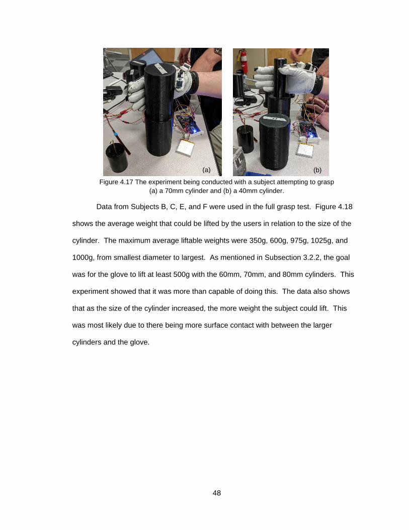
48
Figure 4.17 The experiment being conducted with a subject attempting to grasp
(a) a 70mm cylinder and (b) a 40mm cylinder.
Data from Subjects B, C, E, and F were used in the full grasp test. Figure 4.18
shows the average weight that could be lifted by the users in relation to the size of the
cylinder. The maximum average liftable weights were 350g, 600g, 975g, 1025g, and
1000g, from smallest diameter to largest. As mentioned in Subsection 3.2.2, the goal
was for the glove to lift at least 500g with the 60mm, 70mm, and 80mm cylinders. This
experiment showed that it was more than capable of doing this. The data also shows
that as the size of the cylinder increased, the more weight the subject could lift. This
was most likely due to there being more surface contact with between the larger
cylinders and the glove.
(a) (b)

49
Figure 4.18 Liftable weight in relation to the size of the cylinder.
4.3.4 Assembled Glove Force Generation Results
Force generation by the glove was collected using a force-sensitive resistor
(FSR) connected to an Arduino Mega and Adafruit data shield. This microcontroller
setup was separate from the one being used to control the glove. The microcontroller
was coded to take the analog input of the FSR and convert it to force in Newtons using
Equation (8).
The data shield, shown in Figure 3.6, had an SD card which collected the force
data that was then transferred to the computer for analysis. The FSR was attached to
the largest cylinder the subject could grasp, and force data was captured by each finger
individually. Figure 4.19 shows the setup in use by a subject with the microcontroller
collecting force data from the middle finger.

50
Figure 4.19 A subject grasping the 80mm cylinder with the FSR collecting
force data from the middle finger.
Force data was collected from all six subjects. Figure 4.20 shows the average
force generated by the glove on each digit when the users grasped the widest cylinder
they could with the glove.
Figure 4.20 Force generated by each digit on the cylinder.
As previously stated in Chapter 2, the acceptable range of force generation for
each finger is 3N-5N [1], [18], [20]. The glove is able to generate force within that range
for the index and middle fingers (an average of 4.2N and 4.9N, respectively). The thumb
can apply an average of 10.2N of force with the glove, well beyond the target range.
Cylinder
FSR

51
This makes the total average force generated with the glove to be 19.3N, showing that
the glove can provide adequate force generation to manipulate objects in ADL [1], [18],
[20].
4.3.5 Assembled Glove Muscle Activity Analysis
Muscle activity data from the extensor carpi radialis longus (ECRL), flexor carpi
radialis (FCR), and flexor digitorum superficialis (FDS) was recorded from four subjects.
Two cases were tested. The first case was when the subjects manipulated a weighted
70mm cylinder without the glove and the second case was when they manipulated the
cylinder with the glove. Figure 4.21 shows a subject performing the experiment while
wearing the glove.
Figure 4.21 The EMG reading being acquired while the
subject gets ready to lift the cylinder.
The following plots in Figure 4.22 show the observed muscle activity of the FDS
when the glove was not used and when it was used.
EMGs
Weighted
Cylinder
EMG data
acquisition
software

52
Figure 4.22 Muscle activity of the FDS of Subject B (a) when the glove was not used and the
hand was active, and (b) when the glove was used and the hand was passive.
Figure 4.23 shows the average of the muscle activity while the hand was
manipulating the cylinder during the two cases and the percent decrease in muscle
activity between the case of lifting an object without the glove and with the glove.
Activity decreases 21% in the ECRL, 80.8% in the FCR, and 76.1% in the FDS.
Figure 4.23 (a) Average muscle activity while the cylinder was manipulated. (b) Percent
decrease in muscle activity between the case of lifting an object with and without the glove.
A t-test was also conducted to further compare the muscle activity between the
two cases. Both tests were conducted 20 times (i.e., 4 subjects x 5 repetitions) to
determine the p-values of the three muscles between the two experiments. It was
observed that the glove significantly affected the subjects’ abilities to grasp the cylinder,
with the p-values for all of the muscles being less than 0.01, which can be seen in Table
4.5 along with the average percent differences and standard deviations. These results
(a) (b)
(a) (b)

53
further prove that with the hand being completely passive, the glove is still able to lift
heavy objects. Since the glove is intended for people who just need extra help, not
those who have completely lost their grasping abilities, it should not have any difficulty
assisting with ADL.
Table 4.5 Average percent differences, standard deviations, and pairwise comparison of glove
affecting the muscle activity (* indicates a significant difference between pairs)
Average Percent Difference
Standard Deviation p-value
ECRL 21.0 49.5 < 0.001*
FCR 80.8 25.4 0.0051
FDS 76.1 21.5 < 0.001*

54
CHAPTER 5
CONCLUSION
The purpose of this thesis was to design an assistive glove for people who need
additional help with activities of daily living (ADL). This includes grasping and holding
household objects like a filled water bottle, cans of food, or a tube of lotion. A significant
amount of work went into researching current designs of gloves to see how they worked
and what could be learned from them. A design for the actuation mechanism consisting
of a strip of spring steel attached at one end to a linear actuator and the fingertip at the
other end was devised, and vigorous testing was conducted on it to determine its
feasibility. Once it was proven that the proposed design would work, the rest of the
glove was designed.
The proposed glove was intended to actuate the index finger, middle finger, and
thumb. This was successfully done using two actuation mechanisms with L16 actuators
for the fingers and one mechanism with an L12 actuator for the thumb. The control
system was constructed using an Arduino Mega, an Adafruit Data Shield, and a flex
sensor attached to the pinky finger of the glove. The entire system was powered with a
3.7V 2500mAh LiPo battery giving the glove a maximum run time of 2.5 hours. The goal
was to have the glove and control system weigh less than 500g. The resulting weight
was 400g.
The glove was intended to grasp and lift objects between 60mm and 80mm in
diameter weighing at least 500g while the subject’s hand was completely passive.
Experiments showed that it was it was capable of lifting around double this target. The

55
next goal for the glove was for it to generate 3N-5N in each digit. The glove succeeded
in generating forces within this range for the index and middle fingers and around 10N
for the thumb.
The final experiment was to see if having the glove grasp and lift a heavy object
while the subject’s hand was passive resulted in a noticeable decrease in muscle
activity. Three muscles were tested using EMGs: the extensor carpi radialis longus, the
flexor carpi radialis, and the flexor digitorum superficialis. The results from this
experiment showed that muscle activity decreased 21% in the ECRL and around 80% in
the two flexor muscles. Statistical analysis further proved that the use of the glove
significantly affected the muscle activity and allowed users to grasp objects greater than
500g without the use of their own strength.
All in all, the glove exceeded expectations. The target demographic of the glove
was people with only diminished grasping abilities. However, all of the tests were
conducted while the hand was fully passive. From this analysis, it was shown that the
glove helps in assisting with ADL and can grant those with diminished hand grasping
abilities greater independence.
5.1 Possibilities for Future Investigation
A number of things may be improved to the design and testing of the assistive
glove. Most importantly, more human testing must be done to show stronger evidence
that the glove does what has been claimed. A group of healthy adults over the age of 55
should be brought in for testing, since age is a factor in decreased hand grasping
abilities. Pinch gripping is an important test that many scholars have tested. Similar
experiments should be done with this glove to determine its capabilities in being able to
pick up and hold things like a pen, cooking utensil, or a toothbrush.

56
One thing that was noticed throughout the second half of the research is that the
surface of the glove can affect how much of a grip a user can have on an object. The
golfer’s glove performed well in the test described in Subsection 4.3.3, but if the entire
palmar side was coated with a material of a higher friction coefficient (i.e., silicone or
rubber), the glove may be able to hold even heavier objects, especially those with
smaller sizes.

57
REFERENCES
[1] Dmitry Popov, Igor Gaponov, and Jee-Hwan Ryu, Portable Exoskeleton Glove with
Soft Structure for Hand Assistance in Activities of Daily Living, in IEEE/ASME Trans.
Mechatronics, vol. 22, pp. 865-875, April 2017.
[2] Pinhas Ben-Tzvi and Zhou Ma, Sensing and Force-Feedback Exoskeleton (SAFE)
Robotic Glove, in IEEE Trans. Neural Syst. Rehabil. Eng., vol. 23, pp. 992-1002,
November 2015.
[3] Heidi C. Fischer, et al., Use of a Portable Assistive Glove to Facilitate Rehabilitation
in Stroke Survivors with Severe Hand Impairment, in IEEE Trans. Neural Syst. Rehabil.
Eng., vol. 24, pp. 344-351, March 2016.
[4] Zhou Ma and Pinhas Ben-Tzvi, Design and Optimization of a Five-Finger Haptic
Glove Mechanism, in ASME J. Mechanisms and Robot., vol. 7, November 2015.
[5] Sangwoo Park, Lauri Bishop, Tara Post, Yuchen Xiao, Joel Stein, and Matei
Ciocarlie, On the Feasibility of Wearable Exotendon Networks for Whole-Hand
Movement Patterns in Stroke Patients, in Proc. IEEE Int. Conf. on Robot. Autom (ICRA),
Stockholm, 2016, pp. 3729-3735.
[6] Hong Kai Yap, Phone May Khin, Tze Hui Koh, Yi Sun, Xinquan Liang, Jeong Hoon
Lim, and Chen-Hua Yeow. A Fully Fabric-Based Bidirectional Soft Robotic Glove for
Assistance and Rehabilitation of Hand Impaired Patients, in IEEE Robot. Autom. Letters,
vol. 2, pp. 1383– 1390, July 2017.
[7] Brian Byunghyun Kang, Haemin Lee, Hyunki In, Useok Jeong, Jinwon Chung, and
Kyu-Jin Cho, Development of a Polymer-Based Tendon-Driven Wearable Robotic Hand,
in Proc. IEEE Int. Conf. on Robot. Autom. (ICRA), Stockholm, 2016, pp. 3750-3755.
[8] Benjamin W. Gasser, Daniel A. Bennett, Christina M. Durrough, and Michael
Goldfarb, Design and Preliminary Assessment of Vanderbilt Hand Exoskeleton, in Proc.
IEEE Int. Conf. Rehab. Robot. (ICORR), London, 2017, pp. 1537-1542.
[9] Michael A. Delph II, Sarah A. Fischer, Phillip W. Gauthier, Carlos H. Martinez Luna,
Edward A. Clancy, and Gregory S. Fischer, A Soft Robotic Exomusculature Glove with
Integrated sEMG Sensing for Hand Rehabilitation, in Proc. IEEE Int. Conf. Rehab.
Robot. (ICORR), Seattle, 2013, pp. 1-7.
[10] Hyunki In, Brian Byunghyun Kang, MinKi Sin, and Kyu-Jin Cho, Exo-Glove: A
Wearable Robot for the Hand with a Soft Tendon Routing System, in IEEE Robot.
Autom. Mag., vol. 22, pp. 97-105, March 2015.

58
[11] Christopher J. Nycz, Michael A. Delph, and Gregory S. Fischer, Modeling and
Design of a Tendon Actuated Soft Robotic Exoskeleton for Hemiparetic Upper Limb
Rehabilitation, in Proc. 2015 37th Annu. Int. Conf. of the IEEE Eng. in Med. and Bio.
Soci. (EMBC), Milan, 2015, pp. 3889-3892.
[12] Stuart Biggar and Wei Yao, Design and Evaluation of a Soft and Wearable Robotic
Glove for Hand Rehabilitation, IEEE Trans. Neural Syst. Rehabil. Eng., vol. 24, pp.
1071-1080, October 2016.
[13] Lei Cui, Anthony Phan, and Garry Allison, Design and Fabrication of a Three
Dimensional Printable Non-Assembly Articulated Hand Exoskeleton for Rehabilitation, in
2015 37th Annu. Int. Conf. of the IEEE Eng. in Med. and Bio. Soci. (EMBC), Milan, 2015,
pp. 4627-4630.
[14] N.S.K. Ho, K.Y. Tong, X.L. Hu, K.L. Fung, X.J. Wei, W. Rong, E.A. Susanto, An
EMG-driven Exoskeleton Hand Robotic Training Device on Chronic Stroke Subjects, in
Proc. IEEE Int. Conf. Rehab. Robot. (ICORR), Zurich, 2011, pp. 1-5.
[15] Jumpei Arata, Keiichi Ohmoto, Roger Gassert, Olivier Lambercy, Hideo Fujimoto,
and Ikuo Wada, A new hand exoskeleton device for rehabilitation using a three-layered
sliding spring mechanism, in Proc. IEEE Int. Conf. on Robot. Autom. (ICRA), Karlsruhe,
2013, pp. 3902-3907.
[16] Duojin Wang, Qingyun Meng, Qiaoling Meng, Xinwei Li, and Hongliu Yu, Design
and Development of a Portable Exoskeleton for Hand Rehabilitation, in IEEE Trans.
Neural Syst. Rehabil. Eng., vol. 26, pp. 2376-2386, December 2018.
[17] Yasuhisa Hasegawa, Yasuyuki Mikami, Kosuke Watanabe, and Yoshiyuki Sankai,
Five-Fingered Assistive Hand with Mechanical Compliance of Human Finger, in Proc.
IEEE Int. Conf. on Robot. Autom. (ICRA), Pasadena, 2008, pp. 718-724.
[18] Pinhas Ben-Tzvi, Jerome Danoff, and Zhou Ma, The Design Evolution of a Sensing
and Force-Feedback Exoskeleton Robotic Glove for Hand Rehabilitation Application, in
ASME J. Mechanisms and Robot., vol. 8, October 2016.
[19] Hong Kai Yap, Jeong Hoon Lim, Fatima Nasralla, James C.H. Goh, and Ray C.H.
Yeow, A Soft Exoskeleton for Hand Assistive and Rehabilitation Application using
Pneumatic Actuators with Variable Stiffness, in Proc. IEEE Int. Conf. on Robot. Autom.
(ICRA), Seattle, 2015, pp. 4967-4972.
[20] Panagiotis Polygerinos, Zheng Wang, Kevin C. Galloway, Robert J. Wood, and
Conor J. Walsh, Soft robotic glove for combined assistance and at-home rehabilitation,
in Robot. and Auton. Syst, vol. 73, pp. 135-143, November 2015.

59
[21] Lauri Connelly, Yicheng Jia, Maria L. Toro, Mary Ellen Stoykov, Robert V. Kenyon,
and Derek G. Kamper, A Pneumatic Glove and Immersive Virtual Reality Environment
for Hand Rehabilitative Training After Stroke, in IEEE Trans. Neural Syst. Rehabil. Eng.,
vol. 18, pp. 551-559, October 2010.
[22] Alberto Borboni, Maurizio Mor, and Rodolfo Faglia, Gloreha – Hand Robotic
Rehabilitation: Design, Mechanical Model, and Experiments, in ASME J. Dyn. Syst.,
Meas., Control, vol. 138, November 2016.
[23] Panagiotis Polygerinos, Kevin C. Galloway, Siddharth Sanan, Maxwell Herman, and
Conor J. Walsh, EMG Controlled Soft Robotic Glove for Assistance During Activities of
Daily Living, in Proc. IEEE Int. Conf. Rehab. Robot. (ICORR), Singapore, 2015, pp. 55-
60.
[24] Kotaro Tadano, Masao Akai, Kazuo Kadota, and Kenji Kawashima, Development of
Grip Amplified Glove using Bi-articular Mechanism with Pneumatic Artificial Rubber
Muscle, in Proc. IEEE Int. Conf. on Robot. Autom. (ICRA), Anchorage, 2010, pp. 2363-
2368.
[25] Lucas Gerez, Junan Chen, and Minas Liarokapis, On the Development of Adaptive,
Tendon-Driven, Wearable Exo-Gloves for Grasping Capabilities Enhancement, in IEEE
Robot. Autom. Letters, vol. 4, pp. 422-429, April 2019.
[26] HyunKi In and Kyu-Jin Cho, Evaluation of the antagonistic tendon driven system for
SNU Exo-Glove, in Proc. 2012 9th Int. Conf. on Ubiquitous Robot. and Ambient Intell.
(URAI), Daejeon, 2012, pp. 507-509.
[27] Panagiotis Polygerinos, Kevin C. Galloway, Emily Savage, Maxwell Herman,
Kathleen O’Donnell, and Conor J. Walsh, Soft Robotic Glove for Hand Rehabilitation and
Task Specific Training, in Proc. IEEE Int. Conf. on Robot. Autom. (ICRA), Seattle, 2015,
pp. 2913-2919.
[28] Yongkang Jiang, Diansheng Chen, Jiacheng Que, Zhe Liu, Ziqi Wang, and Ying Xu,
Soft Robotic Glove for Hand Rehabilitation Based on a Novel Fabrication Method, in
Proc. IEEE Int. Conf. Robot. and Biomimetics (ROBIO), Macau 2017.
[29] “Force Sensors.” Tekscan. https://www.tekscan.com/force-sensors (accessed Jan.
18, 2020).
[30] “Standard Sensors.” SingleTact. https://www.singletact.com/micro-force-
sensors/standard-sensors/ (accessed Jan. 18, 2020).

60
[31] “Subminiature Industrial Load Cell, Metric, 0-10 to 0-10,000 Newtons.” Omega
Engineering. https://www.omega.com/en-us/sensors-and-sensing-equipment/load-and-
force/load-cells/p/LCMKD (accessed Jan. 18, 2020).
[32] R. S. Behnke, “Movement,” in Kinetic Anatomy, 3rd ed., Champaign, IL, USA:
Human Kinetics, Inc., 2012, ch. 2, pp. 29-35.
[33] J. Langman and M. W. Woerdeman, “Upper Limb,” in Atlas of Medical Anatomy, 2nd
ed. Philadelphia, PA, USA: W. B. Saunders Company, 1982, ch. 4, pp. 205-272.
[34] W. D. Gardner and W. A. Osburn, “The Muscular System,” in Structure of the
Human Body, 2nd ed., Philadelphia, PA, USA: W. B. Saunders Company, 1973, ch. 4,
pp. 151-238.
[35] “Upper Limb.” BioDigital. https://human.biodigital.com/view?id=39Ut&lang=en
(accessed Jan. 18, 2020).
[36] Christopher J. Nycz, Tobias Bützer, Olivier Lambercy, Jumpei Arata, Gregory S.
Fischer, and Roger Gassert, Design and Characterization of a Lightweight and Fully
Portable Remote Actuation System for Use with a Hand Exoskeleton, in IEEE Robot.
Autom. Letters, vol. 1, pp. 976-983, July 2016.
[37] Tobias Bützer, et al., PEXO – A Pediatric Whole Hand Exoskeleton for Grasping
Assistance in Task-Oriented Training, in Proc. 2019 IEEE Int. Conf. Rehab. Robot.
(ICORR), Toronto, 2019, pp. 108-114.
[38] “L12-R Micro Linear Servos for RC & Arduino.” Actuonix Motion Devices Inc.
https://www.actuonix.com/L12-R-Linear-Servo-For-Radio-Control-p/l12-r.htm (accessed
Feb. 3, 2019).
[39] “L16-R Miniature Linear Servos for RC & Arduino.” Actuonix Motion Devices, Inc.
https://www.actuonix.com/L16-RMiniature-Linear-Servo-For-RC-p/l16-r.htm (accessed
Feb. 3, 2019).
[40] Vinoth K. Ranganathan, Vlodek Siemionow, Vinod Sahgal, and Guang H. Yue,
Effects of Aging on Hand Function, in J. of Amer. Geriatrics Soc., vol. 49, pp. 1478-1484,
November 2001.
[41] Sofia Brorsson, Anna Nilsdotter, Carina Thorstensson, and Ann Bremander,
Differences in muscle activity during hand-dexterity tasks between women with arthritis
and a healthy reference group, in BMC Musculoskeletal Disorders, vol. 15, May 2014.
[42] “Tracker Video Analysis and Modeling Tool for Physics Education.” Physlets.
https://www.physlets.org/tracker/ (accessed Mar. 31, 2020).

61
[43] Daniel A. Bennett, Skyler A. Dalley, Don Truex, and Michael Goldfarb, A Multigrasp
Hand Prosthesis for Providing Precsion and Conformal Grasps, in IEEE/ASME Trans.
Mechatronics, vol. 20, pp. 1697-1704, August 2015.
[44] Sashwati Geed and Peter L. E. van Kan, Grasp-Based Functional Coupling
Between Reach- and Grasp-Related Components of Forelimb Muscle Activity, in J.
Motor Behav., vol. 49, pp. 312-328, September 2016.
[45] Nadine Fligge, Holger Urbanek, Patrick van der Smagt, Relation between object
properties and EMG during reaching to grasp, in J. Electromyography and Kinesiology,
vol. 23, pp. 402-410, April 2013.
[46] Arjan Gijsberts, Manfredo Atzori, Claudio Castellini, Henning Müller, and Barbara
Caputo, Movement Error Rate for Evaluation of Machine Learning Methods for sEMG-
Based Hand Movement and Classification, in IEEE Trans. Neural Syst. Rehabil. Eng.,
vol. 22, pp. 735-744, July 2014.
[47] “Technical Note 101: EMG Sensor Placement.” Delsys.
https://www.delsys.com/downloads/TECHNICALNOTE/101-emg-sensor-placement.pdf
(accessed Mar. 10, 2020).
[48] D. A. Winter, Biomechanics and Motor Control of Human Movement, 4th ed.,
Hoboken, NJ, USA: John Wiley & Sons, Inc., 2009.
[49] Cynthia C. Norkin and D. Joyce White, “The Hand”, in Measurement of Joint Motion:
A Guide to Goniometry, 4th ed. Philadelphia: F.A. Davis, 2009, ch. 7, pp.143-192.

62
APPENDIX
Figure A.1 Design iterations of the dorsal actuator mount.
Figure A.2 Design iterations of the thumb actuator mount.

63
Figure A.3 Design iterations of the thimbles. Model v3 was used in the initial feasibility test.
Figure A.4 Design iterations of the control system box.
(v1)
(v2) Final
version

64
Figure A.5 Design iterations of the spring steel strips.

65
BIOGRAPHY OF THE AUTHOR
Daniel Chizhik was born and raised in Baltimore, Maryland. He graduated from
high school in 2016. He attended the University of Maryland, Baltimore County and
graduated in 2018 with a Bachelor’s degree in Mechanical Engineering. He moved to
Maine and entered the Mechanical Engineering graduate program at the University of
Maine in the summer of 2018. Daniel is a candidate for the Master of Science degree in
Mechanical Engineering from the University of Maine in May 2020.


![Cyborg Glove ExcerptNick and Tesla’s Super Cyborg Gadget Glove [Excerpt]](https://img.dokumen.tips/doc/110x75/577cc47a1a28aba711996e65/cyborg-glove-excerptnick-and-teslas-super-cyborg-gadget-glove-excerpt.jpg)