Embed Size (px)
Citation preview

ISTRUZIONI PER L'INSTALLAZIONE E LA MANUTENZIONE INSTRUCTIONS POUR L'INSTALLATION ET LA MAINTENANCE
INSTRUCTIONS FOR INSTALLATION AND MAINTENANCE INSTALLATIONS- UND WARTUNGSANLEITUNGEN
INSTRUCTIES VOOR INSTALLATIE EN ONDERHOUD INSTRUCCIONES DE INSTALACIÓN Y MANTENIMIENTO
РУКОВОДСТВО ПО МОНТАЖУ И ТЕХНИЧЕСКОМУ ОБСЛУЖИВАНИЮ
BPH-E DPH-E
BPH-E 60/250.40 BPH-E 60/280.50 BPH-E 60/340.65 BPH-E 120/360.80 BPH-E 120/250.40 BPH-E 120/280.50 BPH-E 120/340.65 BPH-E 180/280.50 BPH-E 150/340.65
DPH-E 60/250.40 DPH-E 60/280.50 DPH-E 60/340.65 DPH-E 120/360.80 DPH-E 120/250.40 DPH-E 120/280.50 DPH-E 120/340.65 DPH-E 180/280.50 DPH-E 150/340.65
BPH-E
DPH-E

BPH-E / DPH-E
DICHIARAZIONE DI CONFORMITÀ
La Ditta DAB PUMPS s.p.a. - Via M. Polo,14 - Mestrino (PD) - ITALIA - sotto la propria esclusiva responsabilità dichiara che i prodotti summenzionati sono conformi a: − Direttiva del Consiglio n° 98/37/CE e successive modifiche. − Direttiva della Compatibilità elettromagnetica 89/336 e successive modifiche.
(Normativa di riferimento EN 61800-3) − Direttiva Bassa Tensione 73/23 e successive modifiche.
(Normative di riferimento: EN 60335-1 / EN 60335-2-51)
DÉCLARATION DE CONFORMITÉ
La société DAB PUMPS s.p.a. - Via M. Polo,14 - Mestrino (PD) - ITALIE - sous sa propre responsabilité exclusive déclare que les produits susmentionnés sont conformes à : − Directive du Conseil n° 98/37/CE et modifications successives. − Directive de la Compatibilité électromagnétique 89/336 et modifications successives.
(Norme de référence EN 61800-3) − Directive Basse Tension 73/23 et modifications successives.
(Normes de référence : EN 60335-1 / EN 60335-2-51)
DECLARATION OF CONFORMITY
The Company DAB PUMPS s.p.a. - Via M. Polo,14 - Mestrino (PD) - ITALIA - under its own exclusive responsibility declares that the products listed above comply with: − Council Directive n° 98/37/CE and subsequent modifications. − Directive on Electromagnetic Compatibility 89/336 and subsequent modifications.
(Reference standard EN 61800-3) − Directive on Low Voltage 73/23 and subsequent modifications.
(Reference standards: EN 60335-1 / EN 60335-2-51)
KONFORMITÄTSERKLÄRUNG
Die Firma DAB PUMPS s.p.a - Via Marco Polo, 14 - Mestrino - PD - ITALIEN - erklärt eigenverantwortlich, dass die vorstehend beschriebenen Produkte den folgenden Richtlinien entsprechen: − Maschinenrichtlinie 98/37/EG und folgende Änderungen. − Richtlinie zur elektromagnetischen Verträglichkeit 89/336 und folgende Änderungen.
(Bezugsnorm EN 61800-3) − Niederspannungsrichtlinie 73/23 und folgende Änderungen
(Bezugsnorm: EN 60335-1 / EN 60335-2-51)
OVEREENKOMSTIGHEIDSVERKLARING
De firma DAB PUMPS s.p.a. - Via M. Polo,14 - Mestrino (PD) - ITALIË - verklaart onder haar eigen, exclusieve verantwoording dat de hieronder genoemde producten voldoen aan: − Richtlijn van de raad nr. 98/37/EG en successievelijke wijzigingen. − Richtlijn elektromagnetische compatibiliteit 89/336 en successievelijke wijzigingen.
(Referentienorm EN 61800-3) − Laagspanningrichtlijn 73/23 en successievelijke wijzigingen.
(Referentienorm: EN 60335-1 / EN 60335-2-51)

BPH-E / DPH-E
DECLARACIÓN DE CONFORMIDAD
La empresa DAB PUMPS s.p.a - Via Marco Polo, 14 - Mestrino - PD – ITALIA, bajo su propia y exclusiva responsabilidad declara que los productos enumerados anteriormente cumplen las directivas siguientes: − Directiva de Máquinas n° 98/37/CE y sus modificaciones. − Directiva de Compatibilidad Electromagnética nº 89/336 y sus modificaciones
(Normativa de referencia EN 61800-3). − Directiva de Baja Tensión nº 73/23 y sus modificaciones (Normativas de referencia: EN 60335-1 / EN 60335-2-51).
ЗАЯВЛЕНИЕ О СООТВЕТСТВИИ
Фирма DAB PUMPS s.p.a. – Вия М. Поло, 14 – Местрино (ПД) – ИТАЛИЯ – под собственную исключительную ответственность заявлет, что вышеуказанные изделия соответствуют: − Директиве Европейского Совета n° 98/37/CE и последующим изменениям. − Директиве о электромагнитной совместимости 89/336 и последующим изменениям.
(Справочный норматив EN 61800-3) − Директиве по Низкому напряжению 73/23 и последующим изменениям.
(Справочный норматив : EN 60335-1 / EN 60335-2-51)
Mestrino (PD), 14/02/2006
Attilio Conca Legale Rappresentante Legal Representative

ENGLISH
31
1. General 1.1 Safety 1.2 Responsibility 2. Pumped liquids 3. Applications 4. Technical data 4.1 Electrical data 4.2 Operating conditions 4.3 Temperature 4.4 EMC- electromagnetic compatibility 5. Management 5.1 Storage 5.2 Transport 5.3 Weight 6. Installation 6.1 Circulator installation 6.2 Sensor installation 6.3 Dialogue rotation 6.4 Non return valve 7. Electrical connections 7.1 Connecting diagram 7.2 Service terminal board diagram 7.3 Alarm terminal board diagram 7.4 Power supply terminal board diagram 8. Starting 9. Functions 9.1 Regulating modes 9.2 Regulation with constant differential
pressure 9.3 Regulation with proportional differential
pressure 9.4 Regulation with constant curve 9.5 Regulation with constant and
proportional differential pressure depending on temperature 10. Establishing the parameters of the
control panel 10.1 How to enter the Dialogue menu 10.2 Description of symbols 10.3 Control panel settings 10.4 Dialogue display and alarms
Page 31 31 31 31 31 31 31 32 32 32 32 32 32 32 32 32 33 33 34 34 35 36 36 36 36 36 36 37
37
38 38
39
40 42 43 45
1. GENERAL Read this documentation carefully before installation.
Installation, electrical connection and commissioning must be carried out by specialised personnel in compliance with the general and local safety regulations in force in the country in which the product is installed. Failure to comply with these instructions not only causes risk to personal safety and damage to the equipment, but invalidates every right to assistance under guarantee.
Ensure that the product has not suffered any damage during transport or storage. Check that the outer casing is unbroken and in excellent conditions.
1.1 Safety Use is allowed only if the electric system is in possession of safety precautions in accordance with the regulations in force in the country where the product is installed (for Italy CEI 64/2).
1.2 Responsibility The Manufacturer does not vouch for correct operation of the machine or for any damage that it may cause if it has been tampered with, modified and/or run outside the recommended work range or in contrast with other indications given in this manual.
2. PUMPED LIQUIDS The machine is designed and built to pump water free from explosive substances and solid particles or fibres, with a density of 1000 Kg/m³, kinematic viscosity 1mm²/s and non chemically aggressive liquids.
3. APPLICATIONS The circulators of the BPH-E – DPH-E series allow, by using the DIALOGUE (inverter fitted on the motor), an integrated regulation of the differential pressure which allows the performances of the circulator to be adapted to the actual demands of the system. This determines considerable energy saving, a greater possibility of control of the system, and reduced noise. BPH-E – DPH-E circulators are designed for the circulation of: – hot water in heating systems, – water in industrial hydraulic circuits. They cannot be used for the circulation of domestic water and liquid foodstuffs.
4. TECHNICAL DATA 4.1 Electrical data
Supply voltage: 1x230 V 50-60Hz Absorbed power: See electrical data plate Maximum current: See electrical data plate Degree of protection: IP44 Protection class: H

ENGLISH
32
4.2 Operating conditions
Flow rate: from 13.8 to 59.76 m³/ h Head: see table Maximum working pressure: 10 bar Motor construction: CEI 2-3 – CEI 61-69
( EN 60335-2-41 ) Noise: directive EC 89/392/EEC
MODEL
Head
H max (m)
BPH-E 60/250.40 7.3 BPH-E 120/250.40 11 BPH-E 60/280.50 7.4 BPH-E 120/280.50 11 BPH-E 180/280.50 17.5 BPH-E 60/340.65 6.9 BPH-E 120/340.65 10.1 BPH-E 150/340.65 13.7 BPH-E 120/360.80 10.9
DPH-E 60/250.40 7.3 DPH-E 120/250.40 11 DPH-E 60/280.50 8.1 DPH-E 120/280.50 11.8 DPH-E 180/280.50 18.2 DPH-E 60/340.65 7.2 DPH-E 120/340.65 10.4 DPH-E 150/340.65 14 DPH-E 120/360.80 11.1
4.3 Temperature Environment temperature: 0 ÷ 40°C Storage temperature : -10 ÷ 40°C Liquid temperature: up to 110°C according to EN 60335-2-51
T. Max 120°C
4.4 EMC – electromagnetic compatibility– BPH-E, DPH-E circulators respect standard EN 61800-3, in category C2, for electromagnetic compatibility. - Electromagnetic emissions – Residential
environment (in some cases measures to reduce them may be requested).
- Emissions of ducts – Residential environment (in some cases measures to reduce them may be requested).
The models with power lower than 1 kW need a 2.4 mH external filter at input, as requested by standard EN 61000-3-2. 5. MANAGEMENT 5.1 Storage All the circulators must be stored in a dry covered place, with possible constant air humidity, free from vibrations and dust. They are supplied in their original pack in which they must remain until the time of installation. Otherwise the suction and delivery opening must be accurately closed.
5.2 Transport Avoid subjecting the products to needless impacts and collisions. To lift and transport the circulator use lifting devices with the aid of the pallet supplied with it (if contemplated ).
5.3 Weight The adhesive plate on the package shows the total weight of the circulator. 6 INSTALLATION
6.1 Circulator installation − The circulator may be installed in heating systems
either on the delivery pipe or on the return pipe; the arrow on the pump body indicates the direction of flow.
− Install the circulator as much as possible above the minimum boiler level, and as far as possible from curves, elbows and derivations.
− To facilitate control and maintenance operations, install a stop valve both on the suction pipe and on the delivery pipe.
− Before installing the circulator, flush the system accurately with only water at 80°C. Then drain the system completely to eliminate any harmful substance that may have got into circulation.
Always fit the circulator with the motor shaft in a horizontal position, (fig.1)
Always fit the Dialogue in a vertical position (fig.1)
Fig. 1

ENGLISH
33
− Assemble in such a way as to avoid dripping onto the motor and onto the Dialogue both in the installation phase and in the maintenance phase.
− Avoid mixing additives derived from hydrocarbons and aromatic products with the circulating water. The addition of antifreeze, where necessary, is recommended with maximum percentage 30%.
− Attention!! In the event of thermal insulation, ensure that the condensate discharge holes in the motor casing are not closed or partially clogged.
Never insulate the Dialogue and the pressure sensor!!
6.2 Sensor installation To install the pressure sensor perform the following operations: − fit the sensor group only after having installed
the circulator in the system, − fit the O-ring (ref. 95) on the seat of the pump
body, − fit the sensor block, paying attention to the O-
ring, − tighten the 2 screws (ref. 408) to block the
sensor group.
Never clean the sensor with compressed air!!
6.3 Dialogue rotation The Dialogue is supplied already fixed to the motor casing of the circulator, but it may be necessary to rotate it, if the installation is made with the pipes in a horizontal position.
Before rotating the Dialogue, ensure that the circulator has been completely emptied.
To rotate the Dialogue, proceed as follows:
1) Slacken the cable clamp of the pressure sensor fitted on the Dialogue.
2) Remove the 4 retaining screws of the circulator head.
3) Rotate the motor casing with the Dialogue into the correct position, paying particular attention to the connecting cable of the pressure sensor.
Attention!! The Dialogue must always remain in a vertical position!
4) Reposition and tighten the 4 screws that anchor the head of the circulator.
5) Adapt the cable of the pressure sensor and close the cable clamp again.
Attention!! Ensure that the connecting cable of the pressure sensor never comes in contact with the motor casing.
Fig. 2
ENGLISH
34
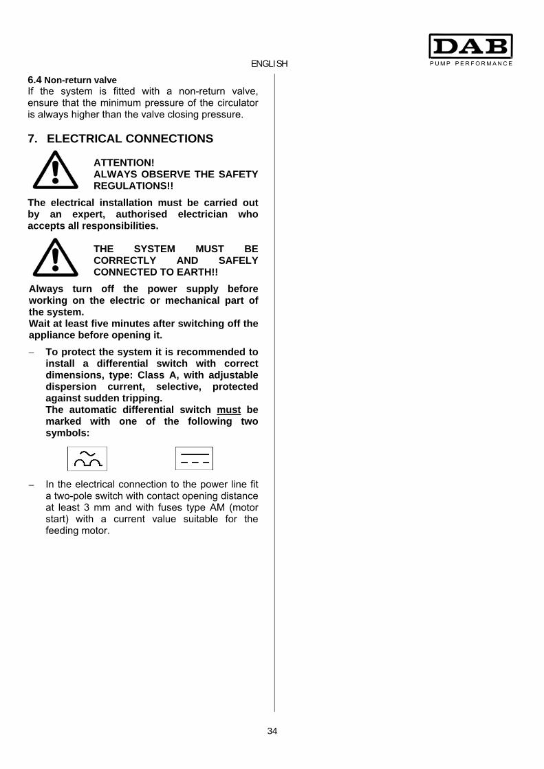
6.4 Non-return valve If the system is fitted with a non-return valve, ensure that the minimum pressure of the circulator is always higher than the valve closing pressure. 7. ELECTRICAL CONNECTIONS
ATTENTION! ALWAYS OBSERVE THE SAFETY REGULATIONS!!
The electrical installation must be carried out by an expert, authorised electrician who accepts all responsibilities.
THE SYSTEM MUST BE CORRECTLY AND SAFELY CONNECTED TO EARTH!!
Always turn off the power supply before working on the electric or mechanical part of the system. Wait at least five minutes after switching off the appliance before opening it.
– To protect the system it is recommended to install a differential switch with correct dimensions, type: Class A, with adjustable dispersion current, selective, protected against sudden tripping. The automatic differential switch must be marked with one of the following two symbols:
– In the electrical connection to the power line fit a two-pole switch with contact opening distance at least 3 mm and with fuses type AM (motor start) with a current value suitable for the feeding motor.

ENGLISH
35
7.1 Wiring diagram Fig. 3
Ref. FUNCTION A Connector for RS 485 remote serial connection B Connector for twin circulators C Connector for sensor on the circulator (standard) D Connector for remote sensor (optional)
1 - 2 (exit) Connecting terminals for remote control 3 - 4 ( E ) Connecting terminals for economy function input
5 - 6 (0 - 10V) Connecting terminals for analog input 0-10V dc
ref. 5 = +10V ref. 6 = 0V
7 - 8 (ALARM) Connecting terminals for remote alarm contact 250V ac 5A
9 - 10 - 11 Connecting terminals for power supply line 1x230V 50-60Hz
ref. 9 = Line ref. 10 = Earth ref. 11 = Neutral
12 - 13 - 14 Faston for connecting the motor cables
ref. 12 = red cable ref. 13 = green cable ref. 14 = white cable
15 Motor earthing screw 16 - 17 Faston for connecting the motor protector – white cable
18 Dialogue display connector 19 Dialogue retaining screw
17 16 15 14 13 12
11
10
9
8
7654321
D
C
B
A
18
19

ENGLISH
36
7.2 Service terminal board diagram Fig. 4 7.3 Alarm terminal board diagram Fig. 5 7.4 Power supply terminal board diagram Fig. 6
The cables connected to the control terminal board must be separated from each other and from the electric power supply with reinforced insulation.
Before supplying power to the circulator ensure that the cover of the Dialogue is perfectly closed!
8. STARTING
All the starting operations must be carried out with the cover of the Dialogue closed! Avoid running the circulator with no water in the system!
− Fill the system and bleed it before running the circulator (Fig. 7).
− The fluid in the system, as well as being at a high temperature and pressure, may also be in the form of steam. BEWARE OF SCALDING!
− It is dangerous to touch the circulator. BEWARE OF SCALDING!
− If it should be necessary to bleed air from the motor, slowly slacken the venting cap and let the fluid flow out for a few seconds (Fig. 7)
− It is dangerous to unscrew the cap rapidly: the high temperature and high pressure fluid can cause scalding.
Fig. 7 9. FUNCTIONS 9.1 Regulating modes With the Dialogue, the circulators BPH-E – DPH-E may be set to operate with different regulating modes depending on the necessities of the system: − Regulation with constant differential pressure. − Regulation with constant differential pressure
depending on the temperature. − Regulation with proportional differential pressure. − Regulation with proportional differential pressure
depending on the temperature. − Regulation with constant curve. − Regulation with constant curve with analog input.

ENGLISH
37
9.2 Regulation with constant differential pressure.
This is set by means of the control panel on the cover of the Dialogue.
The head remains constant, irrespective of the demand for water.
9.3 Regulation with proportional differential pressure.
This is set by means of the control panel on the cover of the Dialogue.
The pressure is reduced or increased as the demand for water falls or rises.
Regulation Type of system Examples
Proportional pressure
In systems with relatively high load losses in the boiler circuits and in the pipes.
1. Heating systems with two pipes with thermostatic valves and with:
− head higher than 4 metres, − very long pipes, − valves with wide operating range, − differential pressure regulators, − high load losses in those parts of the system
where the total quantity of the water flows. − low differential temperature. 2. Underfloor heating systems and systems with
thermostatic valves and large load losses in the boiler circuit.
3. Systems with primary circuit pumps with high load losses.
Constant pressure
In systems with relatively low load losses in the boiler circuits and in the pipes.
1. Heating systems with two pipes with thermostatic valves and with:
− head lower than 2 metres, − natural circulation, − low load losses in those parts of the system
where the total quantity of the water flows. − high differential temperature (centralised
heating). 2. Underfloor heating systems with thermostatic
valves. 3. Single-pipe heating systems with thermostatic
valves and calibrating valves. 4. Systems with primary circuit pumps with low
load losses.
H
Q
H
Q

ENGLISH
38
9.4 Regulation with constant curve. This is set by means of the control panel on the cover of the Dialogue or by means of the analog input 0-10V (ref. terminals 5-6).
The circulator works like a conventional uncontrolled circulator, on constant standard curves. Its rotating speed is kept at a constant number of revs, between nmin and nmax. This type of regulation is particularly indicated when replacing circulators already existing in the systems.
9.5 Regulation with constant and proportional differential pressure depending on the water temperature
This is set by means of the control panel on the cover of the Dialogue.
The set point for the head of the circulator is reduced or increased depending on the water temperature. The temperature of the liquid may be set at 80°C or at 50°C. This type of regulation is particularly indicated: − in systems with a variable flow rate (two-pipe
heating systems), where a further reduction of the circulator performance is ensured depending on the lowering of the temperature of the circulating liquid, when there is a lower demand for heating.
− In systems with a constant flow rate (systems with
single-pipe and underfloor heating), where the performance of the circulator can be regulated only with the function influenced by temperature.
H
Q
Max.
Min.
H
Q
H set.
H min.
20°C 50/80°C
H
T. (°C)

ENGLISH
39
10. ESTABLISHING THE PARAMETERS OF THE CONTROL PANEL The circulators of the BPH-E and DPH-E series must be configured by means of the control panel on the cover of the Dialogue. Fig. 8 Alarm signal red light: If the red light of the alarm signal is blinking the circulator continues operating even when signalling the presence of an error. If the red light of the alarm signal remains fixed the circulator is blocked.
System operating green light: The correct operation of the circulator is indicated by the lighting of the green light.
IR
FAULT RUN
left regulating key right regulating key
central key for confirming parameters and selecting page
control panel
alarm signal red light
system operating green light
infrared communication
concealed regulating key

ENGLISH
40
10.1 How to enter the Dialogue menu Pressing the GREEN KEY + the CONCEALED KEY unblocks the Dialogue.
Pressing the RED KEY moves into the various submenu windows as indicated on page 41. To confirm the parameter hold down the RED KEY until the arrow turns black.
Pressing the GREEN KEYS (right and left) moves inside the menu window. Regulating the Display contrast - The page is accessible from the Home Page of any setting (Master, Slave, Blocked, Not Blocked). - Press the concealed key at bottom right until a half-moon appears on the display. Hold down the right
key for more than 5 seconds to access the display contrast regulating function. Access occurs on releasing the key.
- The page has a central number and a scroll bar which indicates the percentage at which the display contrast is set: - press “+” or “-“ to change the regulation, - to store the setting, hold down the central key for 3 seconds, - to return to the Home Page press the central key.
IR
FAULT RUN
Green keys
Red key
Concealed key

ENGLISH
41
The settings are made when passing from one page to another, in the circulator configuration menu. Fig. 9
Home Page
1.0
2.0
3.0
4.0
5.0
6.07.0
8.0
9.010.0
11.0
Previousalarms
Home Page
11.1
12.0
3.0

ENGLISH
42
10.2 Description of symbols
Displayable quantities:
Symbol Description Shows parameters
Head in metres
Flow rate in m³/h Q < Qmin : when Q is less than 30% of Qmax. Q = 0 : only when the Dialogue is switched off.
Speed in revs/minute (rpm)
Analog input 0-10V
Liquid temperature in °C – input D
Power in kW
Working hours
Liquid temperature in °C – input C
Maximum liquid temperature in °C depending on regulation
Circulator status: Symbol Description
Single circulator or nr. 1
Circulator nr. 2
Alternate twin circulators
Principal/reserve twin circulators
Simultaneous twin circulators
Circulator on
Circulator off
Circulator controlled by remote signal (ref. terminals 1-2)
Type of operation: Symbol Description
Auto function
Economy function
Types of regulation: Symbol Description
Regulation with ∆p-c (constant pressure)
Regulation with ∆p-c depending on temperature with positive increase
Regulation with ∆p-c depending on temperature with negative increase
Regulation with ∆p-v (variable pressure)
Regulation with ∆p-v depending on temperature with positive increase
Regulation with ∆p-v depending on temperature with negative increase
Servomotor regulation with speed set on the display.
Servomotor regulation with speed set by remote signal 0-10V
Various: Symbol Description
Control panel blocked
/ Multifunction key for confirming parameters and scrolling pages

ENGLISH
43
10.3 Control panel settings By means of the control panel it is possible to block or release the circulator settings by holding down simultaneously, for 1-2 seconds, the left key and the concealed key (see fig. 8). If no key is pressed, the settings are blocked automatically after 5 minutes of inactivity. This mode is graphically represented by the presence, on each page, of a key at bottom left, which disappears once the panel is activated, and by the absence of the choice and confirmation symbols. Also, the following pages are not displayed: page 1.0 – page 8.0 – page 10.0 – page 11.0.
Home page:
The Home page graphically sums up the principal settings of the circulator.
The icon at top right indicates the presence of a single or twin circulator.
The movement of the icon or indicates which circulator is operating.
Press the “Menu” key to move on to page 1.0.
Page 1.0:
On Page 1.0 the default settings are restored by pressing the two outside left and right keys simultaneously for 1-2 seconds. The keys will be highlighted and the following symbol will appear at top left:
Press the central key to move on to page 2.0.
Page 2.0:
Page 2.0 sets the regulating mode. There are 8 different modes to choose from (considering also the regulations depending on temperature) :
1. ∆p-c 2. ∆p-c depending on temperature with positive
increase. 3. ∆p-c depending on temperature with negative
increase.
4. ∆p-v 5. ∆p-v depending on temperature with positive
increase. 6. ∆p-v depending on temperature with negative
increase. 7. Servomotor with speed set on the display. 8. Servomotor with speed set by remote signal 0-
10V. Page 2.0 shows three icons which represent: - the central icon, the setting currently selected; - the icon on the right, the setting that can be
selected next; - the icon on the left, the setting selected
previously.
Pressing the outside left or right key selects the different types of regulation available, the reference number of which will appear at top left of the display. This operation will take place cyclically, so after 8 repeats it will return to the initial mode. Hold down for a few seconds the central key “OK”, which will be highlighted - -, to confirm the chosen regulation.
Press the central key to move on to page 3.0. Page 3.0:
Page 3.0 sets the regulating set-point. Depending on the type of regulation chosen on the previous page, the set-point may be set either according to head (H) or to the number of motor revs (RPM). The screen on the page will therefore show H or RPM depending on the regulation chosen on page 2.0. The value may be decreased or increased by pressing the outside left and right keys. Hold down for a few seconds the central key “OK”, which will be highlighted - -, to confirm the value selected.
Press the central key to move on to page 4.0.
Present setting
Next setting
Previous setting
regulation ref.no.

ENGLISH
44
Page 4.0:
Page 4.0 is displayed only if the regulating mode ∆p-c or ∆p-v with set-point depending on temperature has been chosen. On page 4.0, press the outside left and right keys to set the Tmax. (50°C or 80°C) with which to establish dependence on temperature. Hold down for a few seconds the central key “OK”, which will be highlighted - -, to confirm the regulation chosen.
Press the central key to move on to page 5.0.
Page 5.0:
Page 5.0 is displayed in all the pressure regulating modes (∆p) . On page 5.0, press the outside left and right keys to set “auto” or “economy” operating mode. Hold down for a few seconds the central key “OK”, which will be highlighted - -, to confirm the regulation chosen.
Press the central key to move on to page 6.0.
Page 6.0:
Page 6.0 is displayed if “economy” mode has been chosen on page 5.0. On page 6.0, press the outside left and right keys to set the percentage value of reduction of the set point. This reduction will be carried out if a contact is closed between terminals 3-4 ( ). Hold down for a few seconds the central key “OK”, which will be highlighted - - , to confirm the value selected.
Press the central key to move on to page 7.0.
Page 7.0:
On page 7.0, operation with a single or twin circulator can be set. The choice is made by pressing the outside left and right keys. Hold down for a few seconds the central key “OK”, which will be highlighted - - , to confirm the choice made.
Press the central key to move on to page 8.0.
Page 8.0:
Page 8.0 is displayed only if operation with twin circulators has been chosen. On page 8.0, press the outside left and right keys to set one of the 3 possible operating modes:
- Alternate every 24h: - Simultaneous: - Principal/Reserve: Hold down for a few seconds the central key “OK”, which will be highlighted - - , to confirm the regulation chosen.
Press the central key to move on to page 9.0. Page 9.0:
On page 9.0, press the left and right keys to choose the parameter to be displayed on the Home Page. Hold down for a few seconds the central key “OK”, which will be highlighted - - , to confirm the regulation chosen.
Press the central key to move on to page 10.0.
Page 10.0:
On page 10.0, press the left and right keys to choose the language in which the messages are to be displayed.

ENGLISH
45
Hold down for a few seconds the central key “OK”, which will be highlighted - - , to confirm the regulation chosen. Press the central key to move on to page 11.0. Page 11.0:
Page 11.0 shows the alarm history. Press the central key to move on to page 12.0.
Page 12.0:
On page 12.0, press the left and right keys to set the circulator in ON or OFF status, or controlled by a remote signal EXT.
Hold down for a few seconds the central key “OK”, which will be highlighted - - , to confirm the regulation chosen.
Press the central key to return to the Home Page.
You can go from one page to another of the control panel by pressing the central key. To return to the previous page, press the concealed key and the central key. 10.4 Dialogue display and alarms
Alarm Symbol Type of Alarm
E01 “Pump blocked”
E02 “Internal error V18”
E03 “Low mains voltage” (LP)
E04 “High mains voltage” (HP)
E06 “Critical overheating of electronic parts”
W01 “Sensor signal absent”
W02 “Twin communication absent”
W03 “Overheating of electronic parts”
W04 “Fault in cooling systems”

106

107
05/0
6 co
d.00
13.5
96.9
1


