Embed Size (px)
Citation preview
1
A GUIDE TO YOUR 2016 OCCRA ROBOTICS KIT--Part 2 v2.
Written by Mike McIntyre STEM Coordinator
Career Focused Education Oakland Schools
TABLE OF CONTENTS I. KIT MOTORS ……………………………………………………………………… 2
1. VALEO/DENSO/BOSCH WIPER ……………………………………………. 3 2. KEYANG ………………………………………………………………………. 3 3. DEWALT ………………………………………………………………………. 5 4. CIM MOTORS AND TOUGHBOX TRANSMISSIONS…………………… 6 5. THE ANDYMARK GEARMOTOR and the GLOBE MOTOR …………… 6
II. THE PNEUMATIC SYSTEM …………………………………………………….. 7
1. INTRODUCTION ……………………………………………………………… 7 2. OVERVIEW ……………………………………………………………………. 7 3. THE COMPRESSOR …………………………………………………………. 8 4. THE ACCUMULATOR TANK ………………………………………………… 9 5. THE PRESSURE SWITCH …………………………………………………… 10 6. THE REGULATOR …………………………………………………………….. 11 7. DIRECTIONAL CONTROL VALVES ………………………………………… 11 8. FLOW CONTROL VALVES ………………………………………………….. 12 9. PNEUMATIC LIMIT SWITCHES (RELEASE VALVES) …………………… 13 10. PNEUMATIC ACTUATORS ………………………………………………… 14 11. COMPRESSOR RELAY …………………………………………………….. 14
III. ELECTRICAL INPUT DEVICES ………………………………………………….. 14
1. LIMIT SWITCHES ……………………………………………………………… 16 2. POTENTIOMETERS …………………………………………………………… 16
IV. PROGRAMMING …………………………………………………………………… 16 APPENDIX I: 2016 OCCRA MOTOR COMPARISON CHART …………………… 17 APPENDIX II: SAFETY PRECAUTIONS FOR THE OCCRA …………………….. 18 APPENDIX III: OCCRA Mission Statement ……………………………………….. 20 APPENDIX IV: THE DEFAULT VEX PROGRAM CHART ……………………….. 21 APPENDIX V: MODIFYING THE DEFAULT VEX PROGRAM ………………….. 22 APPENDIX VI: THE ELECTRO –PNEUMATIC CONTROL SYSTEM ………….. 23
2
I. KIT MOTORS There are several different motors in your kit this year but teams are not limited to kit motors. All 12V DC motors that are rated below 350 Watts and are available on-line from BaneBot, AndyMark, the Robot Space and VEX are allowed in OCCRA for 2016. There are no restrictions on the quantity of any motor(s) but teams are encouraged to keep three other constraints in mind when designing their robots: (1) the maximum current used on a robot is limited to 120 Amps by the main circuit-breaker, (2) there is a weight limit (either 115 or 120 pounds max.) placed on the robot, and (3) there are only 10 motor-control signal outputs on the Cortex. Also, teams are reminded that OCCRA will only stock reserve supplies of the motors that are provided in the Kit of Materials and will not be able to provide replacements for motors not found in the current Kit of Materials. OCCRA provides an assortment of motors and transmissions that allow teams using the kit to build highly competitive robots.
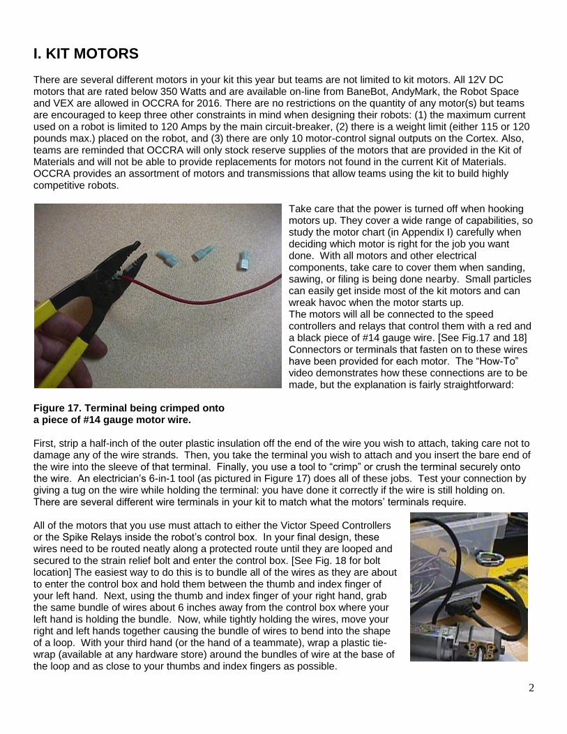
Take care that the power is turned off when hooking motors up. They cover a wide range of capabilities, so study the motor chart (in Appendix I) carefully when deciding which motor is right for the job you want done. With all motors and other electrical components, take care to cover them when sanding, sawing, or filing is being done nearby. Small particles can easily get inside most of the kit motors and can wreak havoc when the motor starts up. The motors will all be connected to the speed controllers and relays that control them with a red and a black piece of #14 gauge wire. [See Fig.17 and 18] Connectors or terminals that fasten on to these wires have been provided for each motor. The “How-To” video demonstrates how these connections are to be made, but the explanation is fairly straightforward:
Figure 17. Terminal being crimped onto a piece of #14 gauge motor wire. First, strip a half-inch of the outer plastic insulation off the end of the wire you wish to attach, taking care not to damage any of the wire strands. Then, you take the terminal you wish to attach and you insert the bare end of the wire into the sleeve of that terminal. Finally, you use a tool to “crimp” or crush the terminal securely onto the wire. An electrician’s 6-in-1 tool (as pictured in Figure 17) does all of these jobs. Test your connection by giving a tug on the wire while holding the terminal: you have done it correctly if the wire is still holding on. There are several different wire terminals in your kit to match what the motors’ terminals require. All of the motors that you use must attach to either the Victor Speed Controllers or the Spike Relays inside the robot’s control box. In your final design, these wires need to be routed neatly along a protected route until they are looped and secured to the strain relief bolt and enter the control box. [See Fig. 18 for bolt location] The easiest way to do this is to bundle all of the wires as they are about to enter the control box and hold them between the thumb and index finger of your left hand. Next, using the thumb and index finger of your right hand, grab the same bundle of wires about 6 inches away from the control box where your left hand is holding the bundle. Now, while tightly holding the wires, move your right and left hands together causing the bundle of wires to bend into the shape of a loop. With your third hand (or the hand of a teammate), wrap a plastic tie-wrap (available at any hardware store) around the bundles of wire at the base of the loop and as close to your thumbs and index fingers as possible.
3
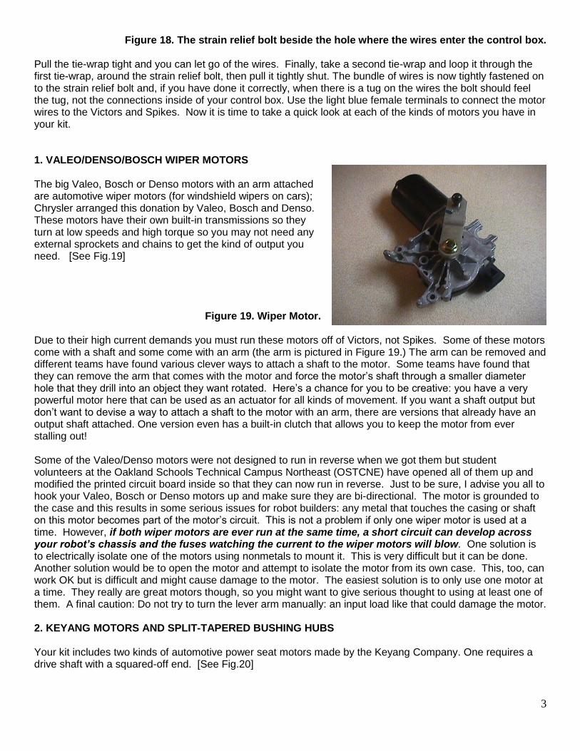
Figure 18. The strain relief bolt beside the hole where the wires enter the control box. Pull the tie-wrap tight and you can let go of the wires. Finally, take a second tie-wrap and loop it through the first tie-wrap, around the strain relief bolt, then pull it tightly shut. The bundle of wires is now tightly fastened on to the strain relief bolt and, if you have done it correctly, when there is a tug on the wires the bolt should feel the tug, not the connections inside of your control box. Use the light blue female terminals to connect the motor wires to the Victors and Spikes. Now it is time to take a quick look at each of the kinds of motors you have in your kit. 1. VALEO/DENSO/BOSCH WIPER MOTORS The big Valeo, Bosch or Denso motors with an arm attached are automotive wiper motors (for windshield wipers on cars); Chrysler arranged this donation by Valeo, Bosch and Denso. These motors have their own built-in transmissions so they turn at low speeds and high torque so you may not need any external sprockets and chains to get the kind of output you need. [See Fig.19]
Figure 19. Wiper Motor.
Due to their high current demands you must run these motors off of Victors, not Spikes. Some of these motors come with a shaft and some come with an arm (the arm is pictured in Figure 19.) The arm can be removed and different teams have found various clever ways to attach a shaft to the motor. Some teams have found that they can remove the arm that comes with the motor and force the motor’s shaft through a smaller diameter hole that they drill into an object they want rotated. Here’s a chance for you to be creative: you have a very powerful motor here that can be used as an actuator for all kinds of movement. If you want a shaft output but don’t want to devise a way to attach a shaft to the motor with an arm, there are versions that already have an output shaft attached. One version even has a built-in clutch that allows you to keep the motor from ever stalling out! Some of the Valeo/Denso motors were not designed to run in reverse when we got them but student volunteers at the Oakland Schools Technical Campus Northeast (OSTCNE) have opened all of them up and modified the printed circuit board inside so that they can now run in reverse. Just to be sure, I advise you all to hook your Valeo, Bosch or Denso motors up and make sure they are bi-directional. The motor is grounded to the case and this results in some serious issues for robot builders: any metal that touches the casing or shaft on this motor becomes part of the motor’s circuit. This is not a problem if only one wiper motor is used at a time. However, if both wiper motors are ever run at the same time, a short circuit can develop across your robot’s chassis and the fuses watching the current to the wiper motors will blow. One solution is to electrically isolate one of the motors using nonmetals to mount it. This is very difficult but it can be done. Another solution would be to open the motor and attempt to isolate the motor from its own case. This, too, can work OK but is difficult and might cause damage to the motor. The easiest solution is to only use one motor at a time. They really are great motors though, so you might want to give serious thought to using at least one of them. A final caution: Do not try to turn the lever arm manually: an input load like that could damage the motor. 2. KEYANG MOTORS AND SPLIT-TAPERED BUSHING HUBS Your kit includes two kinds of automotive power seat motors made by the Keyang Company. One requires a drive shaft with a squared-off end. [See Fig.20]

4
Because this squaring of the shaft ends required precision machining, students at OSTCNE made some for each team in the league and will make some for you if you need more. These motors are very robust and are "thermally protected". This means that if you attempt to drive a load that is too great and the motors begin to stall, they will turn themselves off before the internal heat builds to a destructive level. Simply put: you won't be frying these motors. There is a downside to this over-current protection, however. You may find someday that your robot is in the heat of competition, literally and figuratively, when one of your Keyang motors shuts down on you unexpectedly. This happens because the motor, although cool at the start of the match, has become too warm. If this happens it means you were probably overloading the motor and approaching the stall condition. The resulting rise in current causes the motor windings to heat up and the Keyang's internal sensor trips an integral circuit breaker, shutting off the motor. The motor will remain off a short while until the temperature in the motor has cooled down. Hopefully, your driver’s temper will have a chance to cool off also!
Figure 20. Two Keyang motors driving a single shaft. Each Keyang motor can directly run one or two shafts at a time. It is also possible to drive a single shaft with two motors: try it and see! You should recall that the sprockets in the kit are easily attached to the motor shafts by the "split-tapered bushings" [See Fig.21] that came with your kit. Use care when tightening the bushing's mounting screws that: 1) the screws are each run through the larger set of holes on the bushing before being tightened onto the holes on the sprocket, and 2) the screws are tightened in an alternating sequence (and just a little at a time) until the bushing seats snugly inside the sprocket's opening. Do not tighten one screw all the way and then move on to the next screw: this will put the bushing out of alignment and may cause damage. If you need to remove a bushing from a sprocket, you will find it difficult as the tapered hub was driven tightly into the sprocket when you tightened the mounting screws down. Fortunately, the designers thought of this and provided you with a way out: remove the mounting screws and thread them through the small bushing holes. You will find that the screws will push the sprocket away from the bushing with great force (after all, screws are a simple machine that can give you an increased mechanical advantage). Remember: only tighten each screw down a little at a time and alternate between them. Figure 21. Sprocket with Split-tapered Bushing Another way to attach a shaft to a gear is by using a “trantorque” device. They are no longer in the kit of materials supplied by OCCRA but they can be purchased from manufacturing supply companies and used to attach to the 12-tooth sprockets a little differently. Each trantorque has a collar with hexagonal fitting that holds the assembly together; do not completely unscrew the collar or the whole assembly will come apart in your hands! To attach a 12-tooth sprocket to a ¼” shaft, first insert the trantorque mechanism into the hub of the 12-tooth sprocket while the collar is slightly loosened. Next, insert the ¼” shaft into the center hole of the trantorque and align the shaft so that it extends through the sprocket to the desired length. Finally, tighten the
5
hexagonal collar on the trantorque by turning it clockwise. The collar will draw the trantorque into the hole, forcing a set of wedge-shaped pieces inside of it to pinch tightly against the shaft and the walls of the sprocket’s hub. Be careful not to over-tighten these guys: they do break and they are not cheap! It’s better to under-tighten them then check to see if the sprocket slips when you turn the shaft. If it slips, tighten a little more. If it does not slip, leave it alone.
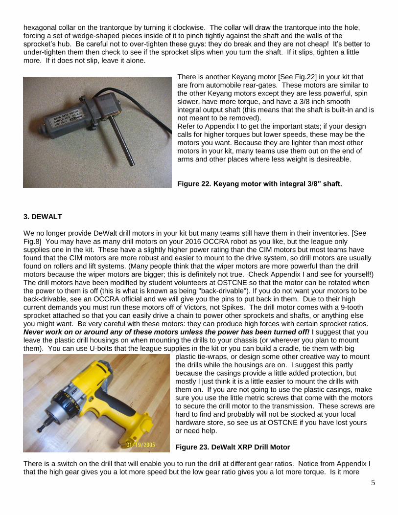
There is another Keyang motor [See Fig.22] in your kit that are from automobile rear-gates. These motors are similar to the other Keyang motors except they are less powerful, spin slower, have more torque, and have a 3/8 inch smooth integral output shaft (this means that the shaft is built-in and is not meant to be removed). Refer to Appendix I to get the important stats; if your design calls for higher torques but lower speeds, these may be the motors you want. Because they are lighter than most other motors in your kit, many teams use them out on the end of arms and other places where less weight is desireable. Figure 22. Keyang motor with integral 3/8” shaft.
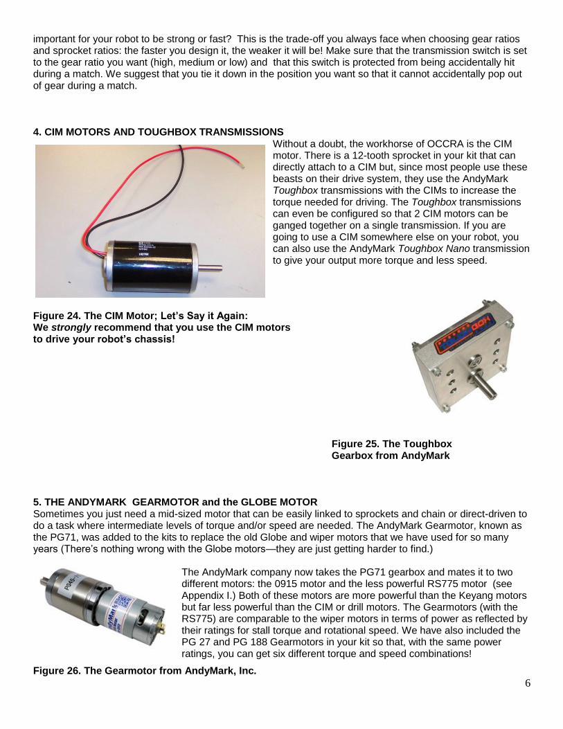
3. DEWALT We no longer provide DeWalt drill motors in your kit but many teams still have them in their inventories. [See Fig.8] You may have as many drill motors on your 2016 OCCRA robot as you like, but the league only supplies one in the kit. These have a slightly higher power rating than the CIM motors but most teams have found that the CIM motors are more robust and easier to mount to the drive system, so drill motors are usually found on rollers and lift systems. (Many people think that the wiper motors are more powerful than the drill motors because the wiper motors are bigger; this is definitely not true. Check Appendix I and see for yourself!) The drill motors have been modified by student volunteers at OSTCNE so that the motor can be rotated when the power to them is off (this is what is known as being "back-drivable"). If you do not want your motors to be back-drivable, see an OCCRA official and we will give you the pins to put back in them. Due to their high current demands you must run these motors off of Victors, not Spikes. The drill motor comes with a 9-tooth sprocket attached so that you can easily drive a chain to power other sprockets and shafts, or anything else you might want. Be very careful with these motors: they can produce high forces with certain sprocket ratios. Never work on or around any of these motors unless the power has been turned off! I suggest that you leave the plastic drill housings on when mounting the drills to your chassis (or wherever you plan to mount them). You can use U-bolts that the league supplies in the kit or you can build a cradle, tie them with big
plastic tie-wraps, or design some other creative way to mount the drills while the housings are on. I suggest this partly because the casings provide a little added protection, but mostly I just think it is a little easier to mount the drills with them on. If you are not going to use the plastic casings, make sure you use the little metric screws that come with the motors to secure the drill motor to the transmission. These screws are hard to find and probably will not be stocked at your local hardware store, so see us at OSTCNE if you have lost yours or need help. Figure 23. DeWalt XRP Drill Motor
There is a switch on the drill that will enable you to run the drill at different gear ratios. Notice from Appendix I that the high gear gives you a lot more speed but the low gear ratio gives you a lot more torque. Is it more
6
important for your robot to be strong or fast? This is the trade-off you always face when choosing gear ratios and sprocket ratios: the faster you design it, the weaker it will be! Make sure that the transmission switch is set to the gear ratio you want (high, medium or low) and that this switch is protected from being accidentally hit during a match. We suggest that you tie it down in the position you want so that it cannot accidentally pop out of gear during a match. 4. CIM MOTORS AND TOUGHBOX TRANSMISSIONS
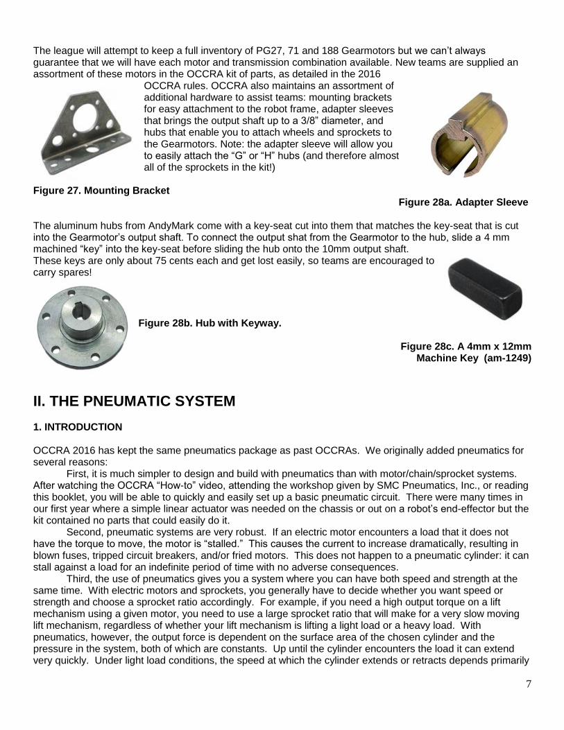
Without a doubt, the workhorse of OCCRA is the CIM motor. There is a 12-tooth sprocket in your kit that can directly attach to a CIM but, since most people use these beasts on their drive system, they use the AndyMark Toughbox transmissions with the CIMs to increase the torque needed for driving. The Toughbox transmissions can even be configured so that 2 CIM motors can be ganged together on a single transmission. If you are going to use a CIM somewhere else on your robot, you can also use the AndyMark Toughbox Nano transmission to give your output more torque and less speed.
Figure 24. The CIM Motor; Let’s Say it Again: We strongly recommend that you use the CIM motors to drive your robot’s chassis! Figure 25. The Toughbox Gearbox from AndyMark 5. THE ANDYMARK GEARMOTOR and the GLOBE MOTOR Sometimes you just need a mid-sized motor that can be easily linked to sprockets and chain or direct-driven to do a task where intermediate levels of torque and/or speed are needed. The AndyMark Gearmotor, known as the PG71, was added to the kits to replace the old Globe and wiper motors that we have used for so many years (There’s nothing wrong with the Globe motors—they are just getting harder to find.)
The AndyMark company now takes the PG71 gearbox and mates it to two different motors: the 0915 motor and the less powerful RS775 motor (see Appendix I.) Both of these motors are more powerful than the Keyang motors but far less powerful than the CIM or drill motors. The Gearmotors (with the RS775) are comparable to the wiper motors in terms of power as reflected by their ratings for stall torque and rotational speed. We have also included the PG 27 and PG 188 Gearmotors in your kit so that, with the same power ratings, you can get six different torque and speed combinations!
Figure 26. The Gearmotor from AndyMark, Inc.
7
The league will attempt to keep a full inventory of PG27, 71 and 188 Gearmotors but we can’t always guarantee that we will have each motor and transmission combination available. New teams are supplied an assortment of these motors in the OCCRA kit of parts, as detailed in the 2016
OCCRA rules. OCCRA also maintains an assortment of additional hardware to assist teams: mounting brackets for easy attachment to the robot frame, adapter sleeves that brings the output shaft up to a 3/8” diameter, and hubs that enable you to attach wheels and sprockets to the Gearmotors. Note: the adapter sleeve will allow you to easily attach the “G” or “H” hubs (and therefore almost all of the sprockets in the kit!)
Figure 27. Mounting Bracket Figure 28a. Adapter Sleeve
The aluminum hubs from AndyMark come with a key-seat cut into them that matches the key-seat that is cut into the Gearmotor’s output shaft. To connect the output shat from the Gearmotor to the hub, slide a 4 mm machined “key” into the key-seat before sliding the hub onto the 10mm output shaft. These keys are only about 75 cents each and get lost easily, so teams are encouraged to carry spares!
Figure 28b. Hub with Keyway.
Figure 28c. A 4mm x 12mm
Machine Key (am-1249)
II. THE PNEUMATIC SYSTEM 1. INTRODUCTION OCCRA 2016 has kept the same pneumatics package as past OCCRAs. We originally added pneumatics for several reasons:
First, it is much simpler to design and build with pneumatics than with motor/chain/sprocket systems. After watching the OCCRA “How-to” video, attending the workshop given by SMC Pneumatics, Inc., or reading this booklet, you will be able to quickly and easily set up a basic pneumatic circuit. There were many times in our first year where a simple linear actuator was needed on the chassis or out on a robot’s end-effector but the kit contained no parts that could easily do it.
Second, pneumatic systems are very robust. If an electric motor encounters a load that it does not have the torque to move, the motor is “stalled.” This causes the current to increase dramatically, resulting in blown fuses, tripped circuit breakers, and/or fried motors. This does not happen to a pneumatic cylinder: it can stall against a load for an indefinite period of time with no adverse consequences.
Third, the use of pneumatics gives you a system where you can have both speed and strength at the same time. With electric motors and sprockets, you generally have to decide whether you want speed or strength and choose a sprocket ratio accordingly. For example, if you need a high output torque on a lift mechanism using a given motor, you need to use a large sprocket ratio that will make for a very slow moving lift mechanism, regardless of whether your lift mechanism is lifting a light load or a heavy load. With pneumatics, however, the output force is dependent on the surface area of the chosen cylinder and the pressure in the system, both of which are constants. Up until the cylinder encounters the load it can extend very quickly. Under light load conditions, the speed at which the cylinder extends or retracts depends primarily
8
upon the amount of airflow and the volume of the cylinder. The cylinder can extend very quickly and deliver large forces.
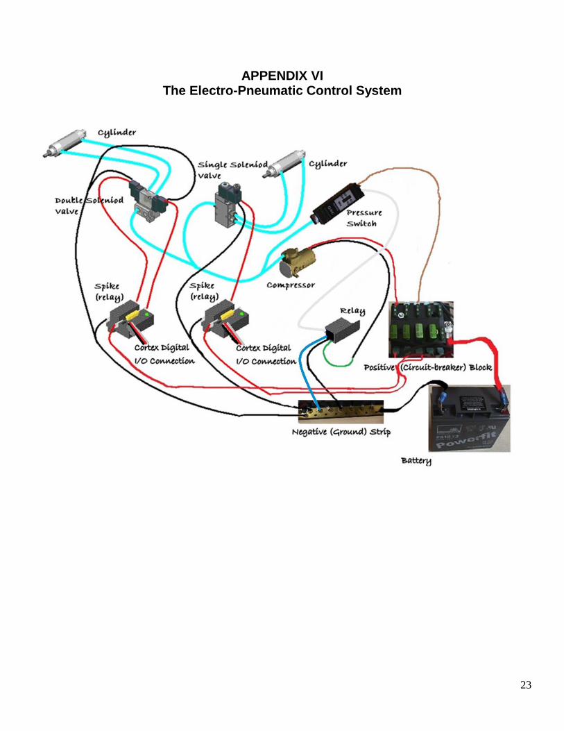
Finally, fluid power systems are extensively used in almost all industries; since we want OCCRA to be educational and meaningful, adding this new kind of system broadens the educational experience in a significant way. The Festo Corporation is OCCRA’s primary sponsor for pneumatics but over the years we have also received support from SMC Pneumatics, Inc. and the Fluid Power Education Association. These organizations have been very supportive of OCCRA because they realize that OCCRA is providing a valuable introduction to this important field. 2. OVERVIEW Pneumatic systems use a gas (typically air) to transmit power through a circuit and do useful work. When a force is applied to an area it produces pressure. (“psi” is short for “pounds per square inch”, the unit used in this booklet to measure air pressure). The term “circuit” refers to the complete path followed by the fluid as it flows from its source to the various output devices. The only pneumatic output devices that you have in your kit this year are the air cylinders. The cylinders in your kit are capable of delivering some very large forces: always stay clear of any cylinder in motion! A hand that gets caught between a stationary object and an extending cylinder is in danger of painful and potentially serious injury. Hydraulic systems are similar to pneumatic systems but they use liquids (usually oil) instead of air. Because of the weight and the mess, don’t expect to see hydraulics in the OCCRA kit anytime soon. Your robot’s pneumatic circuits will all begin with a compressor that pumps the air. This pressurized air then flows through tubing until it gets to air cylinders that can be extended and retracted by the air’s power. Along the way, valves and regulators control the amount of air pressure and the amount and direction of airflow. See Appendix for a pictorial drawing of the Electro-Pneumatic Control System for OCCRA 2016.
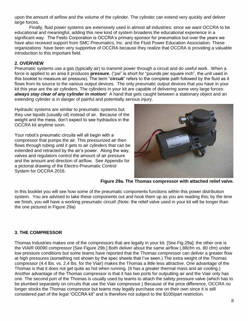
Figure 29a. The Thomas compressor with attached relief valve. In this booklet you will see how some of the pneumatic components functions within this power distribution system. You are advised to take these components out and hook them up as you are reading this; by the time we finish, you will have a working pneumatic circuit! (Note: the relief valve used in your kit will be longer than the one pictured in Figure 29a) 3. THE COMPRESSOR Thomas Industries makes one of the compressors that are legally in your kit. [See Fig.29a]; the other one is the VIAIR 00090 compressor [See Figure 29b.] Both deliver about the same airflow (.88cfm vs. 80 cfm) under low pressure conditions but some teams have reported that the Thomas compressor can deliver a greater flow at high pressures (something not shown by the spec sheets that I’ve seen.) The extra weight of the Thomas compressor (4.4 lbs. vs. 2.4 lbs. for the Viair) makes the Thomas a little less attractive. One advantage of the Thomas is that it does not get quite as hot when running. (It has a greater thermal mass and air cooling.) Another advantage of the Thomas compressor is that it has two ports for outputting air and the Viair only has one. The second port of the Thomas is usually used by teams to attach the safety pressure valve (which has to be plumbed separately on circuits that use the Viair compressor.) Because of the price difference, OCCRA no longer stocks the Thomas compressor but teams may legally purchase one on their own since it is still considered part of the legal “OCCRA kit” and is therefore not subject to the $100/part restriction.
9
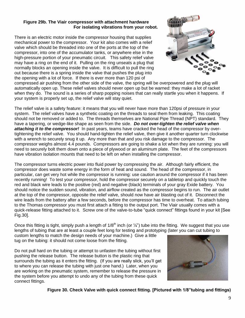
Figure 29b. The Viair compressor with attachment hardware
For isolating vibrations from your robot. There is an electric motor inside the compressor housing that supplies mechanical power to the compressor. Your kit also comes with a relief valve which should be threaded into one of the ports at the top of the compressor, into one of the accumulator tanks, or anywhere else in the high-pressure portion of your pneumatic circuit. This safety relief valve may have a ring on the end of it. Pulling on the ring unseats a plug that normally blocks an opening inside the valve. It is difficult to pull the ring out because there is a spring inside the valve that pushes the plug into the opening with a lot of force. If there is ever more than 120 psi of compressed air pushing from the other side of the valve, the spring will be overpowered and the plug will automatically open up. These relief valves should never open up but be warned: they make a lot of racket when they do. The sound is a series of sharp popping noises that can really startle you when it happens. If your system is properly set up, the relief valve will stay quiet. The relief valve is a safety feature: it means that you will never have more than 120psi of pressure in your system. The relief valves have a synthetic coating on the threads to seal them from leaking. This coating should not be removed or added to. The threads themselves are National Pipe Thread (NPT) standard. They have a tapering, or wedge-like shape as seen from the side. Do not over-tighten the relief valve when attaching it to the compressor! In past years, teams have cracked the head of the compressor by over-tightening the relief valve. You should hand-tighten the relief valve, then give it another quarter turn clockwise with a wrench to securely snug it up. Any more than that and you risk damage to the compressor. The compressor weighs almost 4.4 pounds. Compressors are going to shake a lot when they are running: you will need to securely bolt them down onto a piece of plywood or an aluminum plate. The feet of the compressors have vibration isolation mounts that need to be left on when installing the compressor. The compressor turns electric power into fluid power by compressing the air. Although fairly efficient, the compressor does waste some energy in the form of heat and sound. The head of the compressor, in particular, can get very hot while the compressor is running: use caution around the compressor if it has been recently running! To test your compressor, hold the compressor securely on a tabletop and quickly touch the red and black wire leads to the positive (red) and negative (black) terminals of your gray Exide battery. You should notice the sudden sound, vibration, and airflow created as the compressor begins to run. The air outlet at the top of the compressor, opposite the relief valve, should now have air blasting out of it. Disconnect the wire leads from the battery after a few seconds, before the compressor has time to overheat. To attach tubing to the Thomas compressor you must first attach a fitting to the output port. The Viair usually comes with a quick-release fitting attached to it. Screw one of the valve-to-tube “quick connect” fittings found in your kit [See Fig.30]. Once this fitting is tight, simply push a length of 1/8th inch (or ¼”) tube into the fitting. We suggest that you use lengths of tubing that are at least a couple feet long for testing and prototyping (later you can cut tubing to custom lengths to match the design needs of your machine.) Give a little tug on the tubing: it should not come loose from the fitting. Do not pull hard on the tubing or attempt to unfasten the tubing without first pushing the release button. The release button is the plastic ring that surrounds the tubing as it enters the fitting. (If you are really slick, you’ll get to where you can release the tubing with just one hand.) Later, when you are working on the pneumatic system, remember to release the pressure in the system before you attempt to undo any of the tubing from these quick connect fittings.
Figure 30. Check Valve with quick connect fitting. [Pictured with 1/8”tubing and fittings)

10
There are two styles of quick connect fittings in your kit because there are two kinds of internal thread used on the pneumatic kit components. One fitting has straight threads and a black ring gasket above the threads to seal for leaks. The other fitting has white synthetic material on the NPT threads. If the fitting you are attempting to fasten onto a device does not seem to fit, try the other one. Both are designed for the 1/8” blue tubing that is in your kit. OCCRA now allows a second size of tubing: 1/4”. We began to allow ¼” tubing last year and we will continue to stock spare parts using both tubing sizes. We are in the process of converting over exclusively to the ¼” size but this will probably not occur until next year. 2016 will be a transition year but, after this year, OCCRA will no longer stock 1/8” tubing or fittings. The Viair compressors and some of the Thomas compressors come with a check valve built into them so that air leaving the output port cannot return into the same port. Older Thomas compressors will probably need a discrete check valve to be added to the tube running from the compressor. This tubing must connect first to a check valve [see Fig. 30] that keeps the pressurized air in your circuit and prevents it from returning through the compressor. From the check valve, your tubing run should go to a Y-fitting where the circuit splits: one line should run to your first accumulator tank and the other to a second Y-fitting. At the second Y-fitting, have one line go to your second accumulator tank (if you are using one) and route the other line to the regulator. Remember: you are only allowed to use 60 psi of working pressure on your robot. When you build your pneumatic circuits on the robot, the power to the compressor will not come straight from the battery. Your compressor must get its power from the small black automotive relay found inside the plastic robot control box that houses the electrical control system onboard the robot. Later I will explain how the relay knows when to supply current to the compressor. 4. THE ACCUMULATOR TANK
Your kit contains two accumulator tanks to store the compressed air. Each tank serves as a reservoir for approximately 18 cubic inches of pressurized air. As explained earlier, you may use either one or both on your robot, depending on your machine’s demands. If you only have one or two of the smaller actuators, one tank may be all you need. [See Fig.32] The tank(s) needs to be connected using the quick connect fittings. One of the tanks should have the pressure switch screwed into it. Figure 32. Accumulator Tank
5. THE PRESSURE SWITCH So that the compressor does not have to run continuously, a pressure switch is included in your kit. [See Fig.33] This switch is made by SMC and can be set to click off at anywhere from around 20 psig to 100psig. This setting can be changed (there is a shiny gray screw at on the top of the switch) and we recommend that you screw it all the way clockwise and leave it there. When the robot is powered up, the compressor will run until the 100psig value is reached. This pressure level closes the “normally open” pressure switch, causing the “normally closed” compressor relay to open up. The compressor will then shut off and stay off until the pressure drops because of normal usage or leaks in the circuit.
Figure 33. A Pressure Switch Controls the Compressor.
11
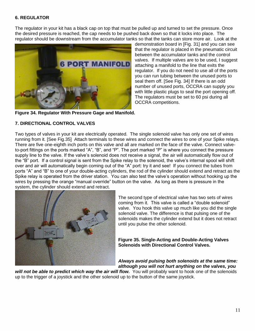
6. REGULATOR The regulator in your kit has a black cap on top that must be pulled up and turned to set the pressure. Once the desired pressure is reached, the cap needs to be pushed back down so that it locks into place. The regulator should be downstream from the accumulator tanks so that the tanks can store more air. Look at the
demonstration board in [Fig. 31] and you can see that the regulator is placed in the pneumatic circuit between the accumulator tanks and the control valves. If multiple valves are to be used, I suggest attaching a manifold to the line that exits the regulator. If you do not need to use all of the ports you can run tubing between the unused ports to seal them off. [See Fig. 34] If there is an odd number of unused ports, OCCRA can supply you with little plastic plugs to seal the port opening off. The regulators must be set to 60 psi during all OCCRA competitions.
Figure 34. Regulator With Pressure Gage and Manifold. 7. DIRECTIONAL CONTROL VALVES Two types of valves in your kit are electrically operated. The single solenoid valve has only one set of wires running from it. [See Fig.35] Attach terminals to these wires and connect the wires to one of your Spike relays. There are five one-eighth inch ports on this valve and all are marked on the face of the valve. Connect valve-to-port fittings on the ports marked “A”, “B”, and “P”. The port marked “P” is where you connect the pressure supply line to the valve. If the valve’s solenoid does not receive a signal, the air will automatically flow out of the “B” port. If a control signal is sent from the Spike relay to the solenoid, the valve’s internal spool will shift over and air will automatically begin coming out of the “A” port: try it and see! If you connect the tubes from ports “A” and “B” to one of your double-acting cylinders, the rod of the cylinder should extend and retract as the Spike relay is operated from the driver station. You can also test the valve’s operation without hooking up the wires by pressing the orange “manual override” button on the valve. As long as there is pressure in the system, the cylinder should extend and retract.
The second type of electrical valve has two sets of wires coming from it. This valve is called a “double solenoid” valve. You hook this valve up much like you did the single solenoid valve. The difference is that pulsing one of the solenoids makes the cylinder extend but it does not retract until you pulse the other solenoid. Figure 35. Single-Acting and Double-Acting Valves Solenoids with Directional Control Valves. Always avoid pulsing both solenoids at the same time: although you will not hurt anything on the valves, you
will not be able to predict which way the air will flow. You will probably want to hook one of the solenoids up to the trigger of a joystick and the other solenoid up to the button of the same joystick.

12
8. FLOW CONTROLS Four flow controls have been included in your kit. [See Fig.36] These flow controls are mounted directly to the ports of your cylinders and will serve to control the speed of your cylinders when they are extending or retracting. A flow control valve allows air to pass without restriction in one direction but limits the flow in the other direction. They do this by an internal architecture that functions like a check valve and a needle valve in parallel arrangement. Figure 36. Flow Control attached to adapter bushing on 10-inch cylinder. An arrow on the flow control shows the direction of the greatest air flow. Turning the thumbscrew clockwise on the flow control valve will cause the needle valve to seat itself and restrict the flow of air in the controlled direction. If this was done to a flow control valve on the line feeding into the cap end of a cylinder, you would have “meter-in flow control” of the cylinder and the cylinder would extend more slowly. The more you tighten down the flow control screw, the slower the cylinder extends. You could also control the speed of a cylinder by controlling the flow of air leaving the cylinder: this would be “meter-out” flow control and would work better in cases like when the load on the cylinder would tend to want to “run away” on you. Imagine you are taking a child for a ride in a toy wagon. Going uphill, you definitely have more control if you pull the wagon handle from the front of the wagon and you are uphill from the wagon. Try pulling from the front when the wagon is going downhill and you’ll quickly realize the control problem as the wagon is smashing into your heels. It is like that with pneumatics, too: there is sometimes a direction the load naturally wants to travel. This may influence which type of arrangement you give the flow control valve. For example: If a double-acting cylinder with the rod-end facing upward has a heavy load pushing downward on the rod, making it naturally want to retract, you are probably going to be better off using the flow control valve to control the air flowing out of the cap end (bottom) of the cylinder during the retraction. 9. PNEUMATIC LIMIT SWITCHES (RELEASE VALVES) You have a set of pneumatic valves in your kit that were donated by SMC Pneumatics. These pneumatic limit switches are actually valves that operate like sensors. [See Fig.37] A “P” marks the port where you hook up your pressure line as explained earlier. Normally, air cannot flow through the valve and so your output port will have no air flowing out of it. If the switch comes into contact with something and the lever gets pushed in, the valve suddenly opens and air begins to flow out of the output port through whatever line you have attached there. Therefore, if you had a pneumatic device (such as a cylinder) and you did not want it to actuate until some contact was made somewhere, adding a pneumatic limit switch in series might solve your problem. Notice the schematic symbols on the side of the valves in your kit show you how the valves function. For the limit switch valve, there are two positions, indicated by the two boxes on the schematic. [See Figure 37] One box shows the air flow is unrestricted while the other box shows a blocked path. All robots need to use one of their valves as a quick-release valve. This valve should be attached to a line coming from one of the accumulator tanks so that it only takes a moment to drain all of the excess air from the tanks whenever the robot is about to be transported.
Figure 37. Pneumatic limit switch

13
10. PNEUMATIC ACTUATORS
There are five pneumatic cylinders, or actuators, in the OCCRA kit. [See Fig.38] The ones with the 4-inch stroke have a single opening (port) and can be run with the single solenoid control valves. [See Fig. 39] These cylinders have a spring inside that will automatically retract them when the signal from the Spike relay ends. The other three cylinders are double acting and will need to be extended and retracted by air power. Either type of control valve can be used to control them. Figure 38. A double-acting cylinder from SMC Notice that the large 10-inch cylinders have a 2-inch bore. The head of the piston inside the cylinder is circular, so the area of the piston head equals “pi”
times the radius squared; since the radius of the largest cylinder is 1”, the area of the piston head must be 3.14 square inches. The OCCRA regulators are required to be set to 60 psi. Since the force of a cylinder is equal to the pressure multiplied by the area of the piston, this means that the large cylinders will each generate around 180 pounds of force while extending. With two of the large cylinders working together, you can generate well over 360 pounds of force!
Figure 39. Single-Acting Cylinder. 11. COMPRESSOR RELAY The compressor on your robot must attach to the 12V automotive relay. The relay is secured with Velcro tape to the bottom of the control box. [See Fig.40] Four wires coming from the relay will need to be attached: 1) the white wire, numbered 86 on the schematic drawing found on the side of the relay, needs to be connected to the pressure switch (the other side of the pressure switch attaches to the positive fuse block). 2) the black wire, numbered 30, needs to connect directly to the positive fuse block; 3) the blue wire, numbered 85, needs to connect to ground, so attach it to the negative (ground) terminal strip inside the control box; and 4) the green wire, numbered 87a, needs to be connected to the red wire coming from the compressor (the black wire from the compressor attaches directly to ground).
Figure 40. The Bosch relay that is used to control current to the Thomas compressor; the pressure switch activates the relay.
14
See Appendix for a pictorial drawing of the Electro-Pneumatic Control System for OCCRA 2016.
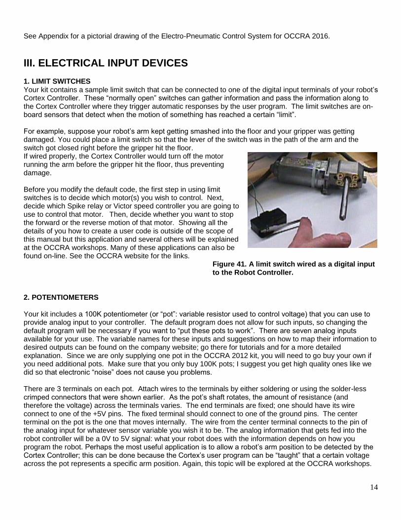
III. ELECTRICAL INPUT DEVICES 1. LIMIT SWITCHES Your kit contains a sample limit switch that can be connected to one of the digital input terminals of your robot’s Cortex Controller. These “normally open” switches can gather information and pass the information along to the Cortex Controller where they trigger automatic responses by the user program. The limit switches are on-board sensors that detect when the motion of something has reached a certain “limit”. For example, suppose your robot’s arm kept getting smashed into the floor and your gripper was getting damaged. You could place a limit switch so that the lever of the switch was in the path of the arm and the switch got closed right before the gripper hit the floor. If wired properly, the Cortex Controller would turn off the motor running the arm before the gripper hit the floor, thus preventing damage. Before you modify the default code, the first step in using limit switches is to decide which motor(s) you wish to control. Next, decide which Spike relay or Victor speed controller you are going to use to control that motor. Then, decide whether you want to stop the forward or the reverse motion of that motor. Showing all the details of you how to create a user code is outside of the scope of this manual but this application and several others will be explained at the OCCRA workshops. Many of these applications can also be found on-line. See the OCCRA website for the links.
Figure 41. A limit switch wired as a digital input to the Robot Controller.
2. POTENTIOMETERS Your kit includes a 100K potentiometer (or “pot”: variable resistor used to control voltage) that you can use to provide analog input to your controller. The default program does not allow for such inputs, so changing the default program will be necessary if you want to “put these pots to work”. There are seven analog inputs available for your use. The variable names for these inputs and suggestions on how to map their information to desired outputs can be found on the company website; go there for tutorials and for a more detailed explanation. Since we are only supplying one pot in the OCCRA 2012 kit, you will need to go buy your own if you need additional pots. Make sure that you only buy 100K pots; I suggest you get high quality ones like we did so that electronic “noise” does not cause you problems. There are 3 terminals on each pot. Attach wires to the terminals by either soldering or using the solder-less crimped connectors that were shown earlier. As the pot’s shaft rotates, the amount of resistance (and therefore the voltage) across the terminals varies. The end terminals are fixed; one should have its wire connect to one of the +5V pins. The fixed terminal should connect to one of the ground pins. The center terminal on the pot is the one that moves internally. The wire from the center terminal connects to the pin of the analog input for whatever sensor variable you wish it to be. The analog information that gets fed into the robot controller will be a 0V to 5V signal: what your robot does with the information depends on how you program the robot. Perhaps the most useful application is to allow a robot’s arm position to be detected by the Cortex Controller; this can be done because the Cortex’s user program can be “taught” that a certain voltage across the pot represents a specific arm position. Again, this topic will be explored at the OCCRA workshops.

15
IV. PROGRAMMING As stated earlier: you do not need to program your robot to play the game: program your robot controller at
your own risk! The default program gives you a great deal of flexibility and many successful teams never change the default program. If you decide you want to have more advanced control of your robot, you must customize the default program and develop what is known as a “user” program. All programming should be done in the “C” or “Robot-C” language. There is a little orange plastic “jumper” that is used to determine which of the default programs your Cortex controller is running (See the chart in Appendix IV.) For example, if you place the plastic jumper into the Digital I/O Port #11, the program that runs will be one where the mode is for two drivers (“dual drivers”) and “tank drive.” This means that the sticks on the primary joystick will control the motor outputs so that left stick can control the left-side motor(s) and the right stick can control the right-side motor(s). When you received the Cortex controller from us, there were no jumpers inserted into the digital inputs of the Cortex so the controller would automatically run tank drive in the single-driver mode.
Figure 42. Downloading a Program via Tether The program that is installed on the Cortex can be changed, becoming a “User” program, but the Cortex can be fairly easily changed back to use one of the default programs in the event of problems with the user program. While there MIGHT be technical assistance with programming available to you at tournaments, do not look to OCCRA officials to bail you out if your program develops bugs. We will try to assist as much as possible but it is a good idea to work out all the bugs BEFORE you go to a tournament. Whether you are downloading the most recent firmware from the internet or a user program that you developed on your computer, you will need to transmit the code by either a direct tether line connection (see Figure 42) or by a wireless connection (see Figure 43.)
Figure 43. Wireless Downloading To run pneumatics on your robot, the Cortex must have some of its I/O ports assigned to be digital outputs and mapped to the input switches you wish to use on your driver joystick controllers. An explanation of this process can be found in Appendix V.
16
V. CONCLUDING THOUGHTS This booklet is not an all-inclusive guide to robot building and is still not complete. I have attempted to hit the essential elements so that you can understand the kit of parts while learning a few scientific principles. The booklet will continue to grow and be updated as OCCRA progresses. Part 3 of the “How-To” has a helpful outline by Tom Rice. Mr. Rice's approach deals with some practical considerations for designing and fabricating to help you develop your ideas and make them happen. I will attempt to update this booklet with corrections, additional resources and points of interest before the first tournament. An OCCRA technical support web page has been set up which can be reached through our host: www.chiefdelphi.com; this site also links from our www.occra.net home page. The web page lists questions that people have submitted along with the answers formulated by the game/kit committee. This group has put together an incredible kit of materials for you. They have worked tirelessly to assemble the kits and devise an exciting game. Furthermore, they have the technical expertise to clear up any of your questions. I want to extend a special thanks to Joe Johnson, Marc Center and Jim Zondag for their assistance in developing this booklet by explaining the workings of the various OCCRA control systems; also, thanks go out to Ken Patton and Norm Peralta for developing the control box and explaining powertrain design, and to Dave Johnson and Sam Skelton for their explanations of pneumatics. Their help was invaluable.
17
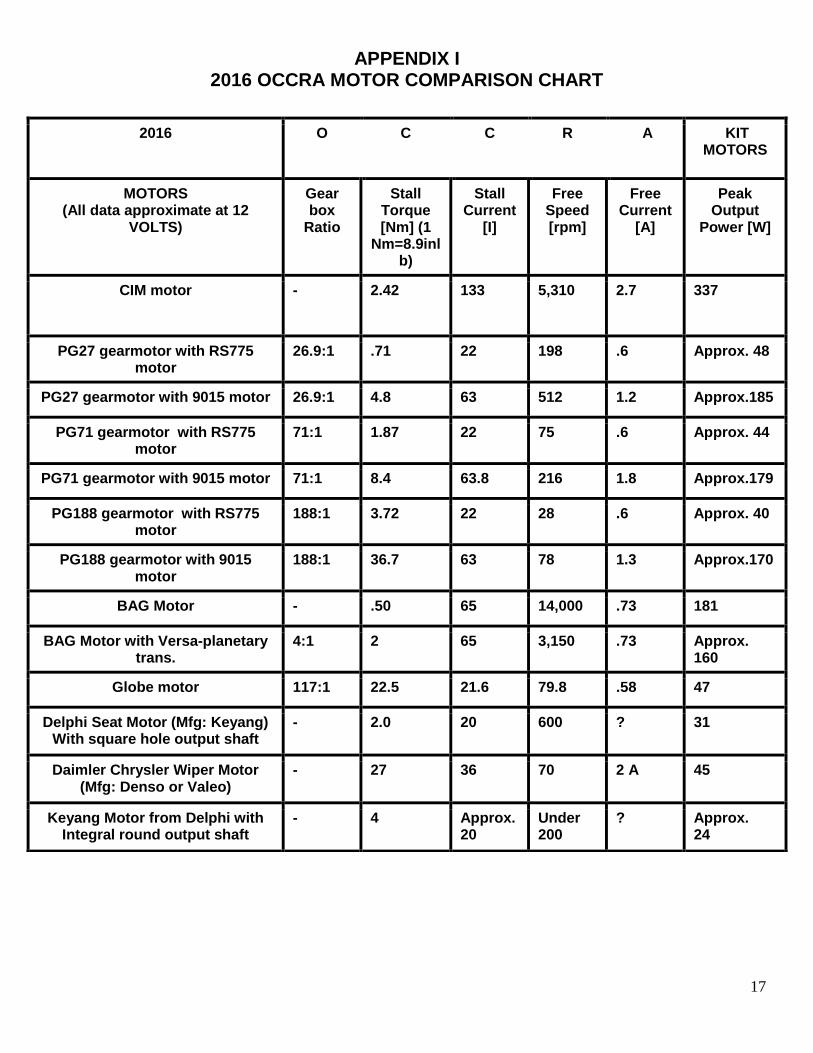
APPENDIX I 2016 OCCRA MOTOR COMPARISON CHART
2016 O C C R A KIT MOTORS
MOTORS (All data approximate at 12
VOLTS)
Gear box
Ratio
Stall Torque [Nm] (1
Nm=8.9inlb)
Stall Current
[I]
Free Speed [rpm]
Free Current
[A]
Peak Output
Power [W]
CIM motor - 2.42 133 5,310 2.7 337
PG27 gearmotor with RS775 motor
26.9:1 .71 22 198 .6 Approx. 48
PG27 gearmotor with 9015 motor 26.9:1 4.8 63 512 1.2 Approx.185
PG71 gearmotor with RS775 motor
71:1 1.87 22 75 .6 Approx. 44
PG71 gearmotor with 9015 motor 71:1 8.4 63.8 216 1.8 Approx.179
PG188 gearmotor with RS775 motor
188:1 3.72 22 28 .6 Approx. 40
PG188 gearmotor with 9015 motor
188:1 36.7 63 78 1.3 Approx.170
BAG Motor - .50 65 14,000 .73 181
BAG Motor with Versa-planetary trans.
4:1 2 65 3,150 .73 Approx. 160
Globe motor 117:1 22.5 21.6 79.8 .58 47
Delphi Seat Motor (Mfg: Keyang) With square hole output shaft
- 2.0 20 600 ? 31
Daimler Chrysler Wiper Motor (Mfg: Denso or Valeo)
- 27 36 70 2 A 45
Keyang Motor from Delphi with Integral round output shaft
- 4 Approx. 20
Under 200
? Approx. 24
18
APPENDIX II SAFETY PRECAUTIONS FOR THE
OAKLAND COUNTY COMPETITIVE ROBOTICS ASSOCIATION As in all high school athletic competition, OCCRA competition carries an element of risk to the participants. The physical risk to students in an OCCRA competition, however, is much less than in other types of high school athletic competitions since robots substitute for students as the play pieces and therefore receive the contact. Getting tackled by a 200lb. linebacker running full speed puts a student football player at a far greater risk than any robot would ever pose. When a baseball player is at bat and is facing an 80 mph fastball or, as a base runner, must try to get past the catcher at home plate, significant risks are involved. Sprained/broken ankles, concussions, torn ACL’s (in knees)…etc. are all common occurrences in even “non-contact” sports like basketball, track and soccer. We could make small, toy-sized robots for OCCRA, but the Mission of OCCRA dictates that it be a good spectator sport that generates enthusiasm and celebrity for our students. To put OCCRA on the same level of spectator excitement as sporting events, large play pieces (i.e. robots) are necessary. The size of the robots (120 lb. max.) and the forces needed to move them lead to some inherent risks. Although these risks are small compared to what is currently accepted in high school sports, they still need to be minimized. An effort has been made to identify the primary risks and address them in OCCRA’s operating procedures. Furthermore, OCCRA volunteers at all tournaments work to remind people of these risks and the safety procedures outlined in the rules. The physical risks have been classified into 3 categories: electrical, mechanical, and chemical:
ELECTRICAL SAFETY 12 V sealed lead-acid batteries power the robots. The operator controllers, although they plug into 120VAC outlets, have transformers that drop the voltage to 12 VDC. This eliminates electric shock as a serious concern. Injury due to burns and electrical fires is still possible. The 12 V batteries are capable of delivering large amounts of current in the case of a short circuit. This current surge could turn normal wires into toaster coils. Even in normal operation, a stalled motor can become dangerously hot. To reduce this risk, fuses and circuit breakers have been added to all circuits on the robot as part of a pre-assembled robot control box that all teams are given; this way, the circuits are properly protected. Teams simply have to attach motor wires to the speed controllers and relays that are already protected properly. It is against the rules to do any modification to the control box. This rule is explained at Kickoff, is repeated several times in the rule book, is discussed at all workshops, and is mentioned on the “How-To” video tape. On the outside of the control box there is a “Master” kill switch (circuit breaker) which teams must leave easily accessible. This button shuts off all power to the robot the moment it is pushed. Robots must go through a safety inspection at all tournaments and these safety features are checked to insure compliance. Finally, the official control station at all tournaments can instantly shut off signals and power to any robot if a safety concern is raised during a match. During the building phase there will not be much control from the OCCRA volunteers. Teams need to enforce the safety rules within their own schools, but the OCCRA planning committees has attempted to give them all the procedures, advice and training they need to make it happen.
MECHANICAL SAFETY The biggest safety concerns are with mechanical issues. Injury to the eye is possibly the greatest single danger. All people in the pit areas are required to wear safety glasses, which OCCRA provides if needed. There are also some safety glasses included in the kit of materials and all mentors are urged to demand that students wear them while working on their machines. During competitions, OCCRA referees monitor that all student drivers and coaches are wearing their safety glasses. Injury through the misuse of tools is also a very real threat to safety. Precise machining (welding, lathe, milling) is forbidden by OCCRA rules and this eliminates many of the more dangerous machining tools. Furthermore, a list of “legal” tools has been included in the rulebook. Still, a student could break the rule and use a table saw, for example. It is not possible for OCCRA to police such transgressions; the OCCRA planners emphasize the rules and rely on the adult team leader(s) to keep watch. The risk of hand tools and
19
small power tools remains. Cuts, abrasions, and other traumas, while not as serious, are still going to happen. OCCRA planners continue to inform and warn student and adult participants through the rulebook, workshops, videos…etc. Remember that moving joints, whether on your robot’s arm or on a set of pliers, creates “pinch-points” that can cause painful and possibly serious injuries to hands and arms. All OCCRA participants must be aware of the potential dangers and be ever vigilant! The pneumatic devices and the motors on a robot can develop dangerous forces. Make sure that all power is turned off and all air pressure is released before working on a robot or transporting it. Do not allow anybody to stand near a robot that has been powered up. I carelessly walked in front of a live robot at a tournament last year and had a toenail ripped off when the robot suddenly and unexpectedly backed up. I will never make that mistake again; if you understand the level of pain I experienced, you will never let it happen to you, either. CHEMICAL SAFETY The lead-acid batteries used in OCCRA are sealed, so there is virtually no risk of acid burns. There are no chemicals in the kit that are dangerous to the general population. A few of the components contain nickel plating and there is some latex tubing in the kit. Teams should check with their members to see if any have severe nickel or latex allergies. The latex can be easily avoided. The nickel is a little harder to spot and, therefore, it is harder to avoid. The main electrical connections in the kits have been soldered for the teams by OCCRA volunteers, and the organizers supply solderless terminals for the others. Some teams may still choose to make solder connections. These teams are warned that soldering wire connections creates fumes that can pose a health risk if the work site is not properly ventilated. HEARING PROTECTION Working with machinery such as electric saws can sometimes generate potentially harmful levels of noise. Students should never be subjected to noise levels that are painful, or even irritating. Coaches should supply hearing protection devices, such as sound-absorbing earplugs, when students are working in noisy environments. OCCRA events will have PA systems and large speakers so that music and announcements can reach everywhere inside the fieldhouse: do not stand directly in front of these speakers! We try to temper the volume of the sound so that the excitement remains but hearing is protected—it’s a difficult balance but let OCCRA staff know if you feel you need a hearing protection device and earplugs will be provided. Address questions or concerns regarding OCCRA and safety to: [email protected]

20
APPENDIX III Oakland County
Competitive Robotics Association
Mission: The Oakland County Competitive Robotics Association (OCCRA) shall organize and administer a high school competitive robotics league in Oakland County for the purpose of:
1) Generating enthusiasm for technical and academic disciplines such as design, engineering, physics, mathematics, and electronics through student designed and built robots 2) Providing a format for integrating and applying diverse scientific, technical, and other areas of study within the high school curriculum 3) Providing recognition and encouragement for students who devote their energies to these technical, scientific, and other areas of study 4) Promoting team/workplace skills and good sportsmanship 5) Raising awareness within high schools of the diverse technical career options available in our county and state 6) Creating partnerships with corporations and the educational community that will enrich the high school experience for our students by providing greater accessibility to people in scientific and technical careers.

21
APPENDIX IV THE DEFAULT VEX PROGRAM CHART
[See the CORTEX Microcontroller and Joystick Quick Start Guide for more details; THIS CHART MAPS OUT WHICH INPUT IS ASSIGNED TO EACH OUTPUT.]
22
APPENDIX V MODIFYING THE DEFAULT VEX PROGRAM TO CREATE DIGITAL OUTPUTS
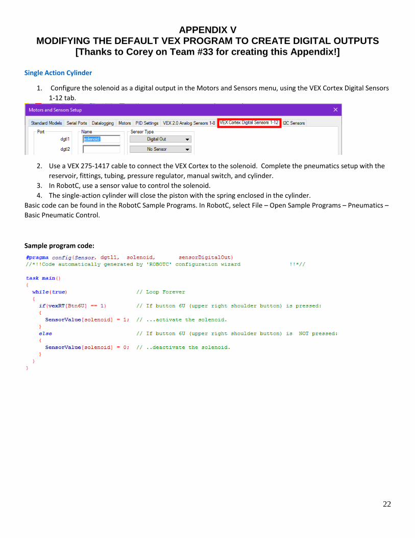
[Thanks to Corey on Team #33 for creating this Appendix!] Single Action Cylinder
1. Configure the solenoid as a digital output in the Motors and Sensors menu, using the VEX Cortex Digital Sensors
1-12 tab.
2. Use a VEX 275-1417 cable to connect the VEX Cortex to the solenoid. Complete the pneumatics setup with the
reservoir, fittings, tubing, pressure regulator, manual switch, and cylinder.
3. In RobotC, use a sensor value to control the solenoid.
4. The single-action cylinder will close the piston with the spring enclosed in the cylinder.
Basic code can be found in the RobotC Sample Programs. In RobotC, select File – Open Sample Programs – Pneumatics –
Basic Pneumatic Control.
Sample program code:
23
APPENDIX VI The Electro-Pneumatic Control System