Embed Size (px)
Citation preview

A Guide to the
Specification and Procurement of
Industrial Process Weighing Systems
The Institute of Measurement and Control 87 Gower Street London WC1E 6AF ISBN 0 904457 32 X
Originally published 2000
Reviewed and re-issued 2014

A Guide to the Specification and Procurement of Industrial Process Weighing Systems COMMITTEE RESPONSIBLE FOR THIS GUIDE This Guide was originally prepared in 2000 by the Weighing Group, reporting to the Measurement Science & Technology Panel. The following served as members of the Group during its preparation: Ural Erdem, Chairman Procon Engineering Ltd Peter Zecchin, Deputy Chairman Nobel Systems Ltd John Anthony UK Weighing Federation Tony Bowen Kvaerner Davy Weighing Systems Gyan Cabral CEL International Ltd David Green DCG Associates Andy Knott National Physical Laboratory Chris Marklew Aston Dane Ltd John Pugh Glasgow Caledonian University Arthur Urwin Quality Scheme for Ready Mixed Concrete John Webb Avery Berkel Ltd Clarry Whittingham British Steel, Scunthorpe This Guide is subject to review at any time by the responsible technical group of the Institute. It was reviewed and re-issued in 2014 - members of the Weighing and Force Measurement Panel at the time of this review were: Andy Knott, Chairman National Physical Laboratory Ural Erdem, Deputy Chairman Consultant Thomas Allgeier Flintec UK Ltd Mike Baker Sherborne Sensors Ltd Paul Dixon National Measurement Office Peter Harrison UKAS Mark Hopkins Procon Engineering Mannie Panesar National Measurement Office John Pugh Glasgow Caledonian University David Smith Avery Weightronix Ltd Ian Turner United Kingdom Weighing Federation Clarry Whittingham Tata Steel The Institute welcomes all comments on this Document and requests that these be addressed to the Institute. Users of this Institute of Measurement and Control Guide shall be responsible for its correct application. This guide refers to other publications that provide information or guidance. The editions listed are believed to be current at the time of publication, but reference should be made to the latest editions. No part of this publication may be reproduced in any form without the prior permission in writing of the Institute of Measurement and Control. Published by the Institute of Measurement and Control Publication Reference Number: WGC1099 ISBN 0 904457 32 X

A Guide to the Specification and Procurement of Industrial Process Weighing Systems
3
CONTENTS PAGE
1 FOREWORD 6
2 SCOPE 7
3 TERMS AND DEFINITIONS 8
4 GENERAL CONSIDERATIONS 12
4.1 HUMAN FACTORS ....................................................................................................................................................... 12 4.1.1 Design and installation 12 4.1.2 Calibration, adjustment, and maintenance 13 4.1.3 Training of personnel 13 4.1.4 Access to the system by untrained personnel 13
4.2 FACTORS RELATING TO THE SELECTION OF LOAD CELLS .......................................................................... 13 4.2.1 Number of load cells 13 4.2.2 Type of load cells 14 4.2.3 Capacity of load cells 14 4.2.4 Use of dummy load cells as pivots 14
4.3 MULTIPLE LOAD CELL APPLICATIONS............................................................................................................... 15 4.3.1 Combination of load cell errors 15 4.3.2 Influence of the rated load output and output resistance 16
4.4 CALIBRATION .............................................................................................................................................................. 17 4.4.1 Use of standard weights 18 4.4.2 Use of reference weights 19 4.4.3 Use of substitute material 19 4.4.4 Use of force transfer method 19 4.4.5 Use of metered flow 20 4.4.6 Use of proving tanks 20 4.4.7 Use of technique remote to the weighing installation 20 4.4.8 Calibration of weighing system components 21
4.5 SYSTEM PERFORMANCE .......................................................................................................................................... 21 4.5.1 Terminal line 22 4.5.2 Best straight line through zero 22 4.5.3 Error specifications based on OIML R 76 (BS EN 45501) 23
4.6 CLEANING AND HYGIENE ........................................................................................................................................ 25
5 SPECIFIC CONSIDERATIONS 27
5.1 TEMPERATURE ........................................................................................................................................................... 27 5.1.1 Load receiving element 27 5.1.2 Load cell 29 5.1.3 Mounting hardware 31 5.1.4 Load bearing structure 31 5.1.5 Junction box and cable 31 5.1.6 Weighing instrumentation 32
5.2 ATMOSPHERIC QUALITY ......................................................................................................................................... 33 5.2.1 Load receiving element 33 5.2.2 Load cell 33 5.2.3 Mounting hardware 34 5.2.4 Load bearing structure 34 5.2.5 Junction box 34 5.2.6 Weighing instrumentation 34
5.3 HUMIDITY..................................................................................................................................................................... 34 5.3.1 Load receiving element 35 5.3.2 Load cell 35

A Guide to the Specification and Procurement of Industrial Process Weighing Systems
4
5.3.3 Mounting hardware 36 5.3.4 Load bearing structure 36 5.3.5 Junction box 36 5.3.6 Weighing instrumentation 36
5.4 PRECIPITATION .......................................................................................................................................................... 36 5.4.1 Load receiving element 37 5.4.2 Load cell 38 5.4.3 Mounting hardware 38 5.4.4 Load bearing structure 38 5.4.5 Junction box and cables 38 5.4.6 Weighing instrumentation 38
5.5 WIND LOADING .......................................................................................................................................................... 38 5.5.1 Load receiving element 39 5.5.2 Load cells 43 5.5.3 Mounting hardware 43 5.5.4 Load bearing structure 44 5.5.5 Junction box 44 5.5.6 Weighing instrumentation 44
5.6 IMPACT .......................................................................................................................................................................... 44 5.6.1 Load receiving element 46 5.6.2 Load cell 48 5.6.3 Mounting hardware 48 5.6.4 Load bearing structure 48 5.6.5 Junction box 48 5.6.6 Weighing instrumentation 48
5.7 VIBRATION ................................................................................................................................................................... 48 5.7.1 Load receiving element 50 5.7.2 Load cell 51 5.7.3 Mounting hardware 51 5.7.4 Load bearing structure 51 5.7.5 Junction box 51 5.7.6 Weighing instrumentation 51
5.8 STRUCTURAL INTERACTION ................................................................................................................................. 51 5.8.1 Load receiving element 52 5.8.2 Load cell 53 5.8.3 Mounting hardware 53 5.8.4 Load bearing structure 54 5.8.5 Junction box 54 5.8.6 Weighing instrumentation 54
5.9 HORIZONTAL RESTRAINING DEVICES ............................................................................................................... 55 5.9.1 Load receiving element 56 5.9.2 Load cell 57 5.9.3 Mounting hardware 57 5.9.4 Load bearing structure 57 5.9.5 Junction box 57 5.9.6 Weighing instrumentation 57
5.10 PIPEWORK ................................................................................................................................................................... 58 5.10.1 Load receiving element 61 5.10.2 Load Cell 62 5.10.3 Mounting hardware 62 5.10.4 Load bearing structure 62 5.10.5 Junction box 62 5.10.6 Weighing instrumentation 62
6 SPECIAL CONSIDERATIONS 63
6.1 HAZARDOUS AREA WEIGHING SYSTEMS .......................................................................................................... 63 6.1.1 Load receiving element 65
A Guide to the Specification and Procurement of Industrial Process Weighing Systems
5
6.1.2 Load cell 65 6.1.3 Mounting hardware 66 6.1.4 Load bearing structure 66 6.1.5 Junction box and cable 66 6.1.6 Weighing instrumentation 67
6.2 ELECTRICAL STORMS AND EARTHING............................................................................................................... 68
6.3 SEISMIC LOADS ........................................................................................................................................................... 69
6.4 RADIATION .................................................................................................................................................................. 71
7 ANNEXES 73
7.1 WEIGHING SYSTEMS SUBJECT TO LEGISLATION ............................................................................................ 73 7.1.1 Introduction 73 7.1.2 Essential requirements 73 7.1.3 NAWI Classification 73 7.1.4 Accuracy performance 74 7.1.5 Testing of NAWIs 75
7.2 SUMMARY OF IP CODES BASED ON BS EN 60529:1992+A2:2013............................................................ 76
7.3 MODEL FORM FOR WEIGHING SYSTEM SPECIFICATION ............................................................................. 77 7.3.1 Standard Form for Weighing System Specification 78 7.3.2 Example 1. Ace Pet Foods, Expansion Project. 81 7.3.3 Example 2, Bulk Silo Company Silo Weighing Project. 85 7.3.4 Example 3. Fine Chemicals Inc., Reactor Vessel Weighing Project. 89
8 REFERENCES 93
9 BIBLIOGRAPHY 94
10 USEFUL ADDRESSES 95
11 INDEX 96

A Guide to the Specification and Procurement of Industrial Process Weighing Systems
6
1 FOREWORD This Institute of Measurement and Control document establishes a uniform guide to specifying industrial process weighing systems, with the exception of continuous weighing systems (such as belt weighers) and dynamic weighing systems (such as in-motion weighers). It gives recognition to the need for a comprehensive and authoritative document for identifying the influence quantities, and other factors, which affect the various elements of the total weighing system. A standardised specification form is included to provide the basis for efficient communication between the user and the provider when procuring these systems. This document is a guide for the technical personnel and organisations engaged in specifying and procuring industrial process weighing systems, and for those organisations supplying such systems.

A Guide to the Specification and Procurement of Industrial Process Weighing Systems
7
2 SCOPE This Guide reviews all of the principal requirements for an industrial process weighing system at its conceptual stage. A standard form is provided as a checklist to identify the relevant specification requirements. The principal influence quantities, which may affect the weighing system and its components, are also presented. These quantities are analysed in detail for their effect on the integrity, operation, and performance of each element of the weighing system as well as their contribution to the total weighing system performance. Where possible and practicable, these influence quantities are quantified, and examples are given to illustrate their contribution and their relevance to the total system performance. Throughout this document a number of expressions are given to estimate the influence quantities in order to appreciate the magnitude of these effects. Many of these expressions are empirical formulae evolved from the experience of the Group members. This document is not intended to present design guidelines and should not be used for the design of weighing systems or any of their components. A weighing system, for the purposes of this document, comprises a measurement system illustrated in Figure 2.1. The load cells are presumed to be of the strain gauge type, but much of the material in the document could be adopted for other load cell technologies.
Figure 2.1 Block diagram of a weighing system
Weighing systems which are subject to statutory requirements, such as those generally referred to as trade weighing systems or approved weighing systems, are not within the scope of this Guide. However a section outlining the basic requirements of these weighing systems is included here to inform the reader of the principal requirements, should such systems be required. The main focus of the Guide is on non-automatic weighing instruments, but some of the included information and principles will also be applicable to certain types of automatic weighing instrument. When a force is calculated, we have also included the value of the mass that would exert the same force under the influence of gravity, e.g. 150 N {15.3 kg} calculated using the standard acceleration of free fall of 9.806 65 ms-2. SI units of measurement have been used throughout the Guide. However, where it is considered helpful, other units of measurement are also stated.

A Guide to the Specification and Procurement of Industrial Process Weighing Systems
8
3 TERMS AND DEFINITIONS This Guide provides recommended terminology and definitions for the terms used herein. No attempt has been made to define those terms defined elsewhere in the document. Some of the acronyms are also included.
Where appropriate, these terms and definitions are based on the currently available British, European, or International standards [10, 11, 15], or other authoritative documents [8, 16, 17]. Refer to Figure 3.1 for a diagrammatic representation of certain weighing terms.
Accuracy of measurement: the closeness of agreement between the result of a load measurement and the true value of the load. The term is unhelpful and is not freely used in this document. Definitions like uncertainty of measurement, non-linearity, combined error and hysteresis are preferred. ATEX: A European New Approach Directive, 94/9/EC, adopted by the European Union for aligning the technical and legal requirements for products intended for use in potentially explosive atmospheres. Blind amplifier: see Transmitter. Buoyancy: vertical upward force on an object due to the fluid medium in which it is immersed. Calibration: a set of operations, which establish under specified conditions the relationship between the value of load applied and the corresponding value of the weighing system output. Note: calibration does not include adjustment. Capacity, maximum operating: the maximum load that may be applied to the load receiving element under normal operating conditions. Capacity, minimum operating: the value of the load applied to the load receiving element, below which the weighing results may be subject to an excessive relative error. Capacity, rated: the maximum load specified by the manufacturer that can be applied to the receiving element. CEN: European Committee for Standardisation. CENELEC: European Committee for Electrotechnical Standardisation. It was set up in 1973 as a non-profit-making organisation under Belgian law. It has been officially recognised as the European Standards Organisation in its field by the European Commission in Directive 83/189/EEC. Centre of gravity: the hypothetical point, through which the centre of mass of a body being weighed can be assumed to act; it can be determined using multi-point support weighing systems using load cells. Check rod: a mechanical restraint designed to prevent tipping or excessive movement of a weighing structure. Such restraints should not interfere with the normal movement of the weighing structure. Combined error (best straight line): the maximum deviation of a weighing system output, obtained for increasing and decreasing applied loads, from a best-fit straight line passing through zero applied load computed using the method of least squares. Combined error (terminal): the maximum deviation of weighing system output, obtained for increasing and decreasing applied loads, from the straight line drawn between zero applied load and maximum applied load. d - division: see scale interval. Dead load: the fixed weight of the weighing structure supported by the load cells. Digital load cell: within the context of this document, a load cell which has a digitised output signal as a function of applied load, as opposed to the conventional load cell which has an analogue output. DSEAR: Dangerous Substances and Explosive Atmospheres Regulations. The ATEX Article 137 was not transposed directly but was implemented by DSEAR. It is a Statutory Instrument (SI 2002 No 2776) introduced into UK Legislation on 9 December 2002. There was a transitional period for full compliance which ended on

A Guide to the Specification and Procurement of Industrial Process Weighing Systems
9
30 June 2006. Dummy load cell: a load support which does not contribute to the output of the weighing system. A dummy load cell is not necessarily a permanent part of the installation - see also pivot. Dynamic weighing: weighing of an object which is in motion. (See also in-motion weigher). Fieldbus: the name of a family of industrial computer network protocols used for real-time distributed control, now standardized as IEC 61158. Flexible coupling: a mechanical means of attaching pipework or services to a weighing structure intended to minimise the force shunt errors. Force shunt: mechanical interference leading to an unwanted force path between a weighing structure and its support structure, such as pipework and tie rods, meaning that not all force is transmitted through the load cells. Galvanic isolator: safety barrier, which is an active device, utilising electronics to isolate and condition the signals. Gross weight: the output of the weighing system with no automatic or pre-set tare device in operation. This does not include dead weight. IEC: International Electrotechnical Commission. Founded in 1906, IEC is the world organisation that prepares and publishes international standards for all electrical, electronic, and related technologies. The IEC was founded as a result of a resolution passed at the International Electrical Congress held in St. Louis (USA) in 1904. The membership consists of more than 50 participating countries. Incremental error: the difference between the indicated value of a load change and the true value of that load change. In-motion weigher: a weighing system where the weighed load is not static, e.g. belt weighers, rolling stock weighers. ISO: International Organisation for Standardisation. A worldwide standards-making body. The scope of ISO covers standardisation in all fields except electrical and electronic engineering standards, which are the responsibility of the IEC. Junction box: an enclosure for the electrical connection of load cells in a weighing system. Live Load: the part of the load intended to be weighed. Load: the weight applied to the load receiving element of the weighing system. Load cell: a measurement device that, in response to an applied force, produces an output. Load receiving element: the element of the weighing system intended to receive the load to be weighed, such as a hopper, silo or ladle. Maximum operating capacity see Capacity, maximum operating Maximum permissible error (MPE): maximum difference allowed, positive or negative, between the weighing system output and the corresponding true value or an agreed value. Minimum operating capacity: see Capacity, minimum operating MPE: see Maximum permissible error. OIML: International Organisation of Legal Metrology. An intergovernmental organisation established by international treaty in 1955 to facilitate trade by harmonisation of measurement units.
A Guide to the Specification and Procurement of Industrial Process Weighing Systems
10
Pivot: an element of a weighing system which supports load but does not itself contribute to the output (see also Dummy load cell). Primary axis: see Principal axis. Principal axis: the axis along which the load cell is designed to be loaded. Rated Capacity: see Capacity, rated Repeatability: the measure of agreement between the results of successive measurements of weighing system output when the same load is applied several times and in a practically identical manner on the load receiving element under constant test conditions. Safety barrier: see Zener barrier or Galvanic isolator. Scale interval, analogue: the difference between the values corresponding to two consecutive scale marks. Scale interval, digital: the difference between the consecutive indicated values. Sensing: within the context of this document, a method of compensating load cell excitation voltage changes in the connecting cables. Sensitivity: the change in output of the weighing system divided by the corresponding load change. Span: the difference between the maximum operating capacity and the zero live load. Tie bar: see Tie rod. Tie rod: a rod or flexure used to restrain the weighing structure laterally. Transmitter: weighing instrumentation with the primary function of providing an output to another device. Weighing range: see Span Weighing structure: part of the weighing system supported by the load cells. Weighing system: a load measuring chain comprising weighing structure, load cell(s) and weighing instrumentation. (See figure 2.1). Weight: see Load. Wind bolt: a check rod usually installed in a vertical direction to prevent the load receiving element toppling due to wind forces. Zener barrier: a safety barrier, which is a passive energy-limiting device, utilising Zener diodes, resistors and fuses to prevent excess voltage and current passing into the hazardous area.
Zero tracking: maintaining the zero indication within certain limits automatically.

A Guide to the Specification and Procurement of Industrial Process Weighing Systems
11
Figure 3.1 Illustration of certain weighing terms

A Guide to the Specification and Procurement of Industrial Process Weighing Systems
12
4 GENERAL CONSIDERATIONS The specification for an industrial process weighing system must include sufficient information relating to its content, operation, performance, and eventual disposal to facilitate clear and unambiguous communication between the supplier and user. Where information is necessary but is not available or cannot be quantified, this should be stated in the specification. If any part of the system is to be installed in a hazardous area, the nature of the hazard and zone of operation must also be specified – see 6 Special Considerations for further details.
The general considerations which follow identify those factors which can influence the design, installation, configuration, reliability, safety, serviceability and cost (either in the short or long term) of the weighing system. These factors may also affect the potential or actual measurement performance of the system. The resultant effects are discussed where relevant. Each of the considerations is cross-referenced from a framework specification contained in 7.3 Model Form For Weighing System Specification.
4.1 HUMAN FACTORS This sub-section identifies a range of human factors that may impact on the weighing system specification. These may be listed as: design and installation; calibration, adjustment, and maintenance; training of personnel; access to the system by untrained personnel. 4.1.1 Design and installation The provision of a load cell based weighing system potentially requires the involvement of a number of disciplines, including civil, mechanical, electrical, instrumentation, and control engineering expertise. The installation of a weighing system cannot be considered as an isolated activity as it may influence and be influenced by the design and construction of the associated plant items. In a retrofitted system significant modifications to existing arrangements may be required. Co-ordination of the various disciplines from an early stage in design is an essential requirement for a successful outcome, and this aspect should be embodied in the specification. A good dialogue between the supplier and the user may significantly improve the final performance of the installed weighing system. This co-operation should be encouraged in addition to the formal contract review procedures, which should be in place to ensure that the proposed equipment is supplied in accordance with the specification. In many cases, factory acceptance testing, witnessed by the client, is undertaken before delivery and installation. This can be a useful exercise in minimising additional onsite costs resulting from modifications. The supplier may be required to work with the client’s own staff on and off-site or with their representatives. It is essential that the lines of communication and responsibility are clear from the outset. The supplier or system designer should make clear in the specification what preparatory work is required and who is expected to execute that work. This will include functions such as modifications to steelwork, installation of load cell assemblies, siting of junction boxes, installing and termination of cables, and locating the electronic items. The provision of safe access to the various weighing system components should be part of the formal design procedure. Access may be of a temporary nature to facilitate installation and commissioning, but on-going requirements for routine calibration and maintenance should not be forgotten.
The specification should also include details of the requirements to supply copies of the final and approved issues or versions of electrical drawings, mechanical construction drawings, and all software produced as part of the contract. The documentation package should also include relevant hazardous area certification and certificates of conformance to all applicable European Union Directives. There may also be a need for the supplier to issue specific installation instructions. It is of great importance that the installation is carried out in accordance with the instructions and/or the drawings by trained personnel. These persons should have an appreciation of the importance of installation requirements such as accurately setting the overload gaps and using the correct grade bolts.
Installation procedures should be developed to ensure that where specific installation information is provided it is adhered to. Where information is not provided, is not understood, or is not available to the site installation engineers at the time of installation, this fact should be made known to a competent authority prior to work
A Guide to the Specification and Procurement of Industrial Process Weighing Systems
13
commencing.
Visits to site by the supplier at critical times during the installation may serve to identify potential problems early and save costs later. It may be considered appropriate to incorporate this requirement into the specification. 4.1.2 Calibration, adjustment, and maintenance The user should be aware at an early stage who is going to maintain the system. In some cases this will be undertaken by the user. However, some companies will wish to employ an external contractor who may be the original supplier. The specification should lay down the requirements for the availability of spare parts, special test equipment, and manpower resources needed to maintain the equipment in the long-term. Calibration and subsequent adjustment requires specialist knowledge and equipment. If the user does not intend to use the original supplier for this function then the specification should allow for the provision of sufficient data and possibly training to enable these adjustments to be made and verified. The user should be satisfied as to the level of competence of any proposed contractor, including the traceability of their measurement equipment – the use of an accredited organisation can demonstrate this competence. Any modifications made to the original equipment during its life should be subject to documented procedures, which should ensure that the functions and performance of the system remain clear. 4.1.3 Training of personnel The training required can be quite wide ranging. In a large organisation with a range of existing weighing systems and expertise, the only requirement may be specialist training relating to specific aspects of the particular weighing system being supplied. It may be adequate to provide this training during the commissioning phase of the project. A new or unfamiliar user, however, may require training in the fundamentals of weighing systems in addition to the particular units being supplied. Such training should include the principles of operation so that the personnel appreciate what factors may influence the performance, some of which may be extremely subtle. This training may be required to be structured and take place either on or off-site. The cost of such training may be significant and may need to be assessed when drafting the original specification. 4.1.4 Access to the system by untrained personnel Probably the greatest danger to the accurate long-term performance of the weighing system is unauthorised alteration. An untrained operative may alter pipework or modify a load cell cable without realising that such actions may have a disastrous effect on the performance of the system. The user should be aware that a load cell might appear as a metal bar to an untrained operative, with no appreciation that a shock, either thermal or mechanical, can do permanent damage. It is unreasonable to expect that all involved with the plant should have knowledge of the factors that can influence the performance. Therefore some thought needs to be given to developing operating procedures that effectively control access to the system.
4.2 FACTORS RELATING TO THE SELECTION OF LOAD CELLS This sub-section considers the factors to be taken into consideration when specifying the number, type and range of load cells for a particular application. The selection of load cells will be influenced by the engineering and commercial judgement of both the user and the supplier. Where possible the specification should be sufficiently flexible to allow for these judgements by making provision for alternative proposals where these can be justified. Minimising the dead load of the system may allow the use of lower capacity load cells, thereby increasing the available signal, the utilisation, and the accuracy. 4.2.1 Number of load cells Any number of load cells can, in theory, be used to support the load receiving element. The number of load cells to be used will depend on one or more of the following factors.
The mechanical design and configuration of the load receiving element and the load bearing structure. This will need to take account of the structural strength of the various load bearing components together with a wide variety of design, economic and safety issues, leading to a proposal that can be integrated into the overall configuration of the plant.
The stability of the load receiving element. This will increase as the area of the support footprint is increased. This may be significant, for example, for systems located outdoors and subject to wind loads.

A Guide to the Specification and Procurement of Industrial Process Weighing Systems
14
Load sharing between load cells is generally more difficult to achieve as the number of supports is increased. For this reason, arrangements using more than four load cells are relatively uncommon except in complicated or very large or heavy structures.
Load cell capacity occasionally affects the number of cells chosen, particularly in high precision systems, where the available measuring signal is required to be maximised (maximising the load cell utilisation).
The way in which load cell signals are combined to provide the total output signal can lead to changes in the overall system performance. This may inform the choice and is fully considered elsewhere (see 4.3 Multiple Load Cell Applications).
There is an obvious advantage in minimising the number of load cells for cost reasons. However, there may be other consequential and subtler cost implications. It is the total installed system costs that should be considered.
4.2.2 Type of load cells Load cells are divided into generic types, generally but not exclusively characterised by the stresses that they measure. Four main types exist: uniaxial, compression or tension cells, bending beams, and shear beams. The type of load cell to be specified will be influenced by the following factors.
The load cell performance characteristics, including measurement errors, temperature coefficients and output parameters. The supplier must ensure that the selected load cell type will have measurement errors compatible with the overall specification of the weighing system (see 4.5 System Performance). It should be noted, however, that the system accuracy specification is an aggregate of errors and the individual load cell figures may not be meaningful or indeed helpful in the context of a system specification.
The ability of the load cell type to withstand and reject forces not along its primary measuring axis. The cell may need to be considered together with its mounting hardware in this context.
The availability of suitable capacities. Differing design types of load cells tend to be manufactured with a particular range of capacities.
The reliability of the load cell in terms of its mechanical construction, material, sealing against moisture ingress, overload capability and temperature range. Attention should also be paid to the electrical connection cables in this context as they can be vulnerable and may need additional protection.
Third party approvals may be required to underwrite the performance, safety or construction of the load cell. This is almost universally the case for hazardous area applications (see 6.1 Hazardous Area Weighing Systems). Where relevant, the details of the certification must form part of the specification.
The type of load cell used will have a cost implication both in its intrinsic unit cost and the cost of any mounting hardware or accessories. The cost of ownership is an important consideration and includes long-term reliability and maintenance requirements.
4.2.3 Capacity of load cells Load cells are manufactured in defined capacity ranges, each having a normal rated load, usually a safe overload capacity and a maximum overload capacity. The range selected will be determined in relation to the loading details both normal and abnormal contained in the specification, and in light of the experience of both supplier and user. The basic approach is to take the maximum total live plus dead load, and divide by the number of support points, then select the next highest range available. This simplistic approach may be modified by the following factors.
Poor load sharing in a multiple load cell system. Unequal loading introduced either by the design of the load receiving element or the distribution of its
contents. Additional abnormal loads and conditions introduced by the operating environment such as wind load,
shock, impact, or vibration. Consideration should also be given to the possible overloading by overfilling of the load receiving element.
Additional abnormal loads and conditions introduced by cleaning or maintenance procedures or by physical abuse.
A need to optimise performance requiring the load cell to be deliberately operated in its safe overload region.
Cost. The final decision may be influenced not only by the component cost, but also by compatibility with existing systems, spares holdings, and availability.
4.2.4 Use of dummy load cells as pivots For applications where the accuracy of the weighing system is not critical and cost considerations are paramount, the use of dummy load cells acting as pivots in combination with live load cells may be considered.

A Guide to the Specification and Procurement of Industrial Process Weighing Systems
15
The most common arrangements are:
the use of one live cell plus two pivots in a three support system; the use of two live cells plus two pivots in a four support system.
Using the nomenclature shown in Figure 4.2.1, the relationship between the measured load Wm and the live load W for the three-point vessel shown is given by:
Figure 4.2.1 Schematic representation of a three point supported vessel - incorporating pivots. Any factor affecting the horizontal position of the centre of gravity in relation to the live load cell(s) will lead to additional measuring errors. In general such systems are of low accuracy and particularly unsuitable for: load receiving elements containing solids; load receiving elements subjected to wind load, agitation loads or other side forces; load receiving elements of non-uniform cross-section or located on sloping load bearing structures.
4.3 MULTIPLE LOAD CELL APPLICATIONS In most industrial process weighing applications it is common practice to use multiple load cells to support the weighed structure and combine the analogue output of these load cells in parallel at a passive junction box or at the input of the weighing instrumentation. The following sub-sections analyse the performance of the combined load cells and their influence on the weighing system. These considerations do not apply to digital load cells as each load cell is accessed individually and the outputs are combined numerically. 4.3.1 Combination of load cell errors The performance of the combined load cells is not the same as the specification given for the individual load cell. It is possible to combine certain errors of the individual load cells, which are statistically random, such as the temperature coefficients of compensated load cells. The expression given below may be used to estimate the combined error for a number n of identical load cells, each having a statistically random relative error of ε.
√
There are a number of types of error, stated in a load cell specification, which are not necessarily random in

A Guide to the Specification and Procurement of Industrial Process Weighing Systems
16
nature and guidance should be sought from the supplier prior to combination of these errors. Examples are the temperature coefficient at rated load output of uncompensated load cells and the non-linearity of load cells, which are of the same capacity, and from the same batch of manufacture.
Example: In a weighing system with four load cells connected in parallel in a junction box, the load cells have the following temperature coefficients, and it is, possibly incorrectly, assumed that all are uncorrelated: on zero load output ±0.002 % C-1 on rated output ±0.001 % C-1 The combined effect may be expected to be:
√
√
4.3.2 Influence of the rated load output and output resistance In applications where the distribution of load changes, such as the weighing of non-self-levelling products, the weighing system output will be sensitive to any mismatch of the sensitivity and the output resistance of the individual load cells. A typical example of this is the change in the position of the centre of gravity when products such as powders and aggregates are weighed. The combined output voltage in a three-load cell application may be given as:
(
)
(
)
(
)
where e0 is the combined open-circuit output voltage;
e1, e2, e3 are the open-circuit output voltages of the load cells 1, 2, and 3; R1, R2, R3 are the output resistances of the load cells 1, 2, and 3.

A Guide to the Specification and Procurement of Industrial Process Weighing Systems
17
Example: Three load cells are used in an aggregate weighing application. It is estimated that the load distribution on the load cells, for each weighing cycle, will change up to 20 % from nominal equal distribution. The load cells installed are specified for the rated load output of 2 mV/V matched to ±0.1 % and the output resistance is given as (350 ± 3) . In this application the actual measured values, with an excitation voltage of 10 V, are as listed below:
load cell no. 1 2 3
output resistance R1 = 347 . R2 = 353 . R3 = 353 .
nominal output e1 = 20.02 mV e2 = 20.00 mV e3 = 19.98 mV
proportion of the load applied W1 = 120 % W2 = 90 % W3 = 90 %
output for unequal load distribution e1 = 24.024 mV e2 = 18.000mV e3 = 17.982 mV
Substituting the above values of the output resistances and the rated outputs, we obtain the combined output, e0, for equal load distribution:
e0 = 20.000 11 mV
With the load distribution as given above, using the same equation we obtain the combined output:
e0 = 20.025 05 mV
The output of the weighing system will be 0.125 % higher when the load is 20 % higher on load cell no.1 compared to equal load distribution. If the rated load outputs were matched to 20.00 mV, the above error would be reduced to 0.115 %. If the output resistances of the load cells were matched to 350 then this error would reduce to 0.01 %. If the excitation voltage is not being measured at the load cells (by using, for example, a six-wire system), voltage drops due to the resistance of the cable (of maybe 1 Ω·m-1) may also need to be considered.
4.4 CALIBRATION It is strongly recommended that the requirements for the calibration of the weighing system should be established as early as possible and preferably at the initial specification stage. The following is a summary of these requirements, which should be considered carefully since they may have considerable cost and design implications. a) Specified accuracy of the weighing system
It is important not to overspecify the required accuracy since the cost of calibration increases steeply with decreasing value of maximum permissible error (MPE) expected from the weighing system. A realistic level of accuracy should be established, taking into account the operating requirements of the system. Careful consideration should be given to the general requirement that the calibration loads applied should not have an expanded uncertainty greater than 1/3 of the maximum permissible error of the weighing system under calibration. That is, if the system is to be calibrated to have an error not greater than 0.03 % then the calibration loads applied need to be accurate to 0.01 %, and in most applications this can only be achieved by the use of standard weights. It is not a practical proposition to calibrate the system using standard weights unless it has a working range lower than a few tonnes or if the load receiving element has a suitable loading surface such as in the case of a weighbridge. Table 4.4.1 lists the relationship between the typical uncertainty of applied calibration load and the best measurement capability of the weighing system under calibration for various methods of calibration.
b) Calibration range This should be up to the maximum operating capacity or over the full working range of the weighing system. Most weighing systems have a larger rated capacity than their operating capacity for reasons such as safety.
c) Calibration frequency The initial period of calibration is governed by factors such as:
manufacturer’s recommendation
A Guide to the Specification and Procurement of Industrial Process Weighing Systems
18
frequency and manner of use environmental influence accuracy sought process requirements consequence of failure
The initially chosen intervals should be reviewed to achieve a sensible balance between cost and risk. [7] presents five methods of review from which the user can select the most appropriate:
Automatic or ‘staircase’ adjustment (calendar-time): in which the confirmation interval is increased if the equipment is found to be within tolerance, or conversely reduced if outside tolerance.
Control chart (calendar-time): in which the same chosen calibration points from successive calibrations are plotted against time. These plots are then treated statistically to predict the drift in calibration and hence determine an efficient recalibration interval.
‘In-use’ time: this is a variation of the above methods but utilising actual hours in use as the confirmation interval rather than elapsed calendar time.
In-service or ‘black-box’ testing: this is a variation on methods 1 & 2 in which certain critical parameters are checked between full confirmations using some form of portable calibration equipment. Clearly non-conformance at this level would prompt a full confirmation.
Other statistical approaches: in which a statistical analysis of an individual instrument or instrument type is performed. Where groups of identical instruments are to be calibrated, the calibration intervals can be reviewed with the help of statistical methods.
d) Requirement for verification in between calibrations
This requirement depends on the critical nature of the process. There may be a requirement to establish a procedure for verifying the weighing system output at one or two load points to ensure that system integrity has not altered since its last calibration.
e) Operating procedure It is essential that the calibration is carried out in a uniform and harmonised manner so that the results obtained over a period of time can be meaningfully compared. A document describing the requirements for calibration, generally referred as the Method Statement, should be produced. The Method Statement should then refer to detailed calibration procedures such as a Standard Operating Procedure (SOP) or Company Operating Procedure (COP). These documents may be produced with the help of the weighing system supplier or the calibration organisation.
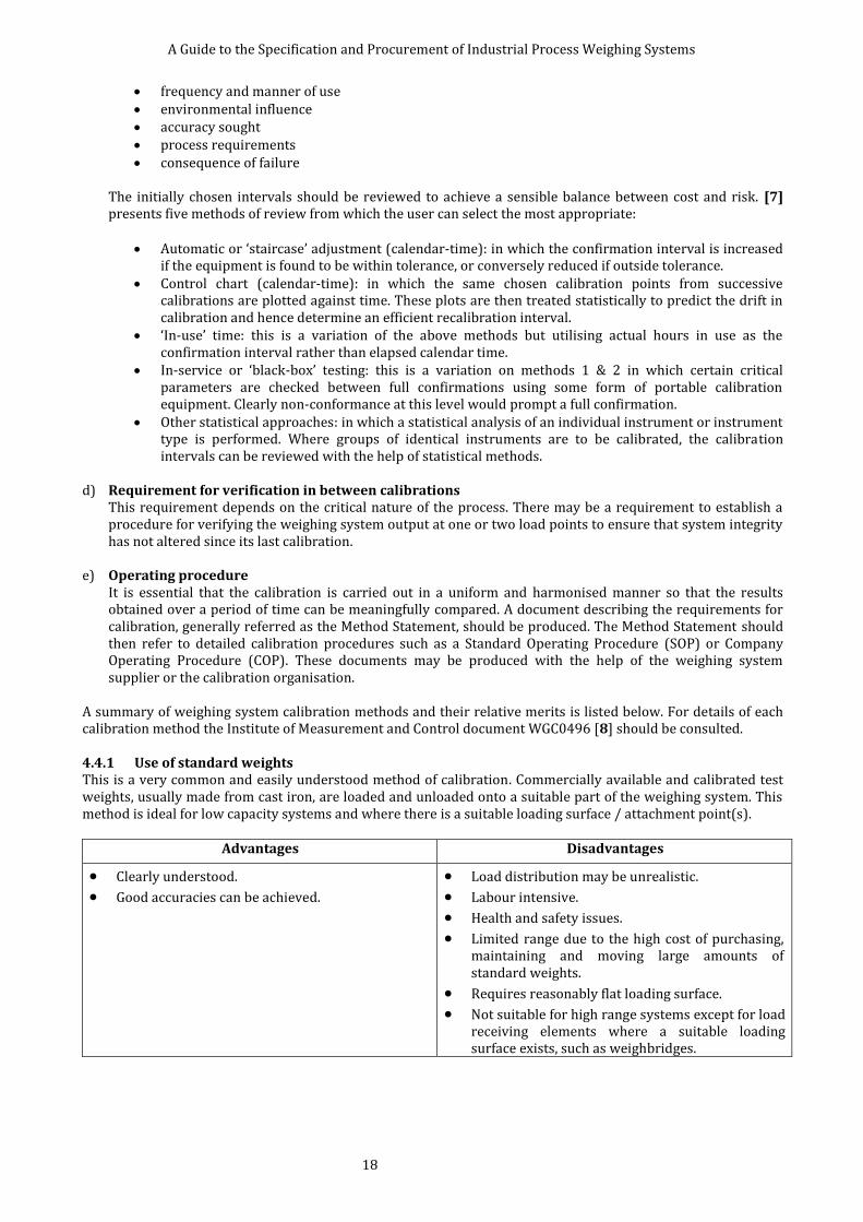
A summary of weighing system calibration methods and their relative merits is listed below. For details of each calibration method the Institute of Measurement and Control document WGC0496 [8] should be consulted. 4.4.1 Use of standard weights This is a very common and easily understood method of calibration. Commercially available and calibrated test weights, usually made from cast iron, are loaded and unloaded onto a suitable part of the weighing system. This method is ideal for low capacity systems and where there is a suitable loading surface / attachment point(s).
Advantages Disadvantages
Clearly understood.
Good accuracies can be achieved.
Load distribution may be unrealistic.
Labour intensive.
Health and safety issues.
Limited range due to the high cost of purchasing, maintaining and moving large amounts of standard weights.
Requires reasonably flat loading surface.
Not suitable for high range systems except for load receiving elements where a suitable loading surface exists, such as weighbridges.

A Guide to the Specification and Procurement of Industrial Process Weighing Systems
19
4.4.2 Use of reference weights An object of any shape or density calibrated against standard weights is used. It is possible to use objects such as a block of concrete, which can be weighed on a calibrated weighbridge immediately prior to use. This method is ideal for revalidation of calibration at specific load points.
Advantages Disadvantages
Clearly understood.
Adaptable and cheaper than comparable standard weights.
Potentially good accuracies can be obtained.
Useful method for large cranes.
Load distribution may be unrealistic.
It is generally difficult to apply a specific load.
Reference weights require calibration immediately prior to use and this may not be practicable.
4.4.3 Use of substitute material An amount of standard or reference weights are used as an incremental load, which is applied to the system. Between each step process material is added to the weigh vessel to replicate the readings obtained from the known weights. This method allows calibration over a much larger range than would otherwise be possible with standard or reference weights.
Advantages Disadvantages
Provision for and use of weights handled may be reduced.
Load distribution is more representative of actual load.
Hysteresis and poor zero return can make the data difficult to interpret.
Difficult to apply decreasing loads to obtain hysteresis data.
Time consuming for high capacity systems.
4.4.4 Use of force transfer method Known and clearly defined loads are applied, in situ, to the load cells of the weighing system to be calibrated. This is achieved by the use of reference load cells, which are calibrated in a force calibration laboratory, together with force generators such as hydraulic jacks or screw jacks placed directly or indirectly in series with these load cells. The application of this method requires mechanical modification to the installation.
Advantages Disadvantages
Fast and efficient calibration, once the existing structure is modified.
There is no theoretical limit of calibration range, which may be from a few hundred kilograms to several thousand tonnes.
Cost-effective, may be used for revalidation in addition to calibration.
Particularly useful for vessels where access is difficult.
It may be difficult to achieve correct load distribution.
May involve high initial cost in modifying the existing structure.
It does not simulate possible vessel distortions such as bulging.
It may ignore the mechanical influences of piping forces and structural deflections.

A Guide to the Specification and Procurement of Industrial Process Weighing Systems
20
4.4.5 Use of metered flow The weigh vessel under calibration is filled with a liquid, usually water, which is metered through an integrating flow meter. The metered volume is converted into weight and used as the load applied to the weighing system. It is popularly used for calibrating large capacity weighing systems where water is freely available and disposable.
Advantages Disadvantages
High-capacity systems may be calibrated.
It may be fast and efficient with the right flow meter and supply of water.
Replicates the actual load distribution for self-levelling products.
Requires large volume of high-pressure water for fast and efficient calibration.
Wasteful of water unless it can be recycled.
Data processing is difficult. For high accuracy calibration temperature and density of the water needs to be considered.
Difficult to use for decreasing loading.
Water is not always compatible with the process material or the load receiving element.
4.4.6 Use of proving tanks Tanks of known and certified volumes are used to discharge known volumes of liquid, usually water, into the weighing system under calibration. This volume is converted into weight by determining the density of the water used.
Advantages Disadvantages
Fast and efficient.
Can be very accurate.
Good load distribution.
Wasteful of water unless it is recycled.
Load data for increasing load only.
Costly due to logistics of handling certified tanks.
Complicated data processing.
Water is not always compatible with the process material or the load receiving element.
4.4.7 Use of technique remote to the weighing installation This method is applicable to the weighing system which may be calibrated out of its normal working installation and where the effect of influences associated with the weighing structure are negligible or acceptable in operation, such as a portable aircraft weighing system.
Advantages Disadvantages
Potentially low-cost operation since actual calibration on site is not carried out.
Applied loads can be very accurate.
Ignores the mechanical influence on the load cells in normal operating location.
It is only acceptable if it can be shown that the mechanical influences from force shunts are negligible.
A comparison of the capabilities of calibration methods and corresponding target measurement accuracies of weighing systems is given in Table 4.4.1. The indication of uncertainty of measurement of the applied load, given in the second column, is only to illustrate the capability of the commonly employed calibration procedures.

A Guide to the Specification and Procurement of Industrial Process Weighing Systems
21
Method of Calibration Expanded Uncertainty of
Calibration Load / % of Applied Load
Calibration Measurement Capability of the Weighing System
/ % of Applied Load
Standard weights 0.005 to 0.05 0.015 to 0.15
Reference weights 0.025 0.075
Substitute material 0.025 0.075
Force transfer method 0.05 0.15
Metered flow 0.03 0.09
Proving tanks 0.015 0.045
Remote calibration 0.01 0.03
Table 4.4.1 A summary of calibration methods and the accuracy requirements.
4.4.8 Calibration of weighing system components There may be installations, such as very large silos containing several hundred tonnes of material, where it is not practicable to carry out full system calibration due to technical reasons or cost considerations. In these instances it may be acceptable to carry out a calibration of some or all of the components of the weighing system. The methods used are based on simulating the load applied to the load cells either electronically or, in the case of Revalidation of Lever Systems, mechanically. They exclude the effects of the force shunts and other mechanical influences, such as inclined loading, which may be present in the installation. A summary of these methods is given below.
a. Use of load cell simulator An electronic device, which simulates the load cells by producing a millivolt signal, is used to replace the output produced by the load cells. The simulator is then adjusted to produce a millivolt signal equivalent to a selected load. This signal is injected into the junction box and the weighing system output is monitored.
b. Use of millivolt source A commercially available millivolt source is used to simulate the load cells. Its millivolt output is adjusted to give a signal equivalent to a selected load. This signal is injected into the junction box.
c. Use of shunt resistors This technique is normally used to check the calibration of the weighing system at one load point. This is established by placing a shunt resistor across one of the arms of the Wheatstone Bridge in the load cell. When activated the load cell output shifts by a predetermined amount and the weighing system output shifts by an equivalent weight.
d. Use of theoretical calculations The relationship between the weighing system output and the load applied to the load receiving element is established by analysing the individual calibration data of the weighing system components such as the load cell and the weighing instrumentation. Where known, the influences of the components such as the interconnecting cables and shunt forces such as pipes and tie bars are also taken into account.
e. Revalidation of lever systems This method is suitable for lever operated weighing systems where a known load is applied at a predetermined position on a lever. This load causes the weighing system output to shift by an equivalent amount.
4.5 SYSTEM PERFORMANCE This sub-section reviews the basic parameters that can be used to specify the accuracy of measurement. The term ‘Accuracy’ is often poorly defined and unhelpful and this document avoids its use except in general terms. Other parameters, which serve to describe measurement errors, are more explicit and are preferred. In the absence of any influence factors the relationship between the weighing system and the applied load will be a continuous curve exhibiting some non-linearity and hysteresis. The exact form of this relationship will be discovered during the calibration procedure and can adopt various forms. Because the exact shape of the calibration curve is not known at the time of specification, some simplified yet concise way of describing the curve must be agreed between the user and the supplier.

A Guide to the Specification and Procurement of Industrial Process Weighing Systems
22
The following methods may be adopted: 4.5.1 Terminal line This is probably the simplest and easiest method to understand. A straight line is drawn between the live load - initial zero and full scales points, on the calibration curve. Two lines are drawn, parallel to this line, which just enclose all points of the calibration curve. The maximum output deviation described by these lines then becomes a measure known as the Combined Error (Terminal). It may be expressed either in weight units or as a percentage of span. Figure 4.5.1 illustrates the interpretation of the various parameters that may be used to define the accuracy of the weighing system based on the terminal straight line.
Figure 4.5.1 Representation of errors using a terminal line.
Example: From the calibration curve of a system having a maximum operating capacity of 1000 kg, the terminal line is drawn and the maximum error measured (c) is determined to be 1 kg. The specification could be written: Combined Error (Terminal) = 1 kg or Combined Error (Terminal) = 0.1 % FS (or Range, or Span) provided it is clear elsewhere in the specification as to what the % figure relates.
4.5.2 Best straight line through zero This method may provide an error specification which is less demanding than those based on the terminal straight line, but is no less valid for that.

A Guide to the Specification and Procurement of Industrial Process Weighing Systems
23
A straight line is computed which best fits the data used to draw the calibration curve. The slope of the curve is calculated by the method of least squares and must originate from the initial live load zero. Again two parallel lines are drawn which just enclose all the points of the calibration curve. The maximum deviation described by these lines then becomes a measure known as the Combined Error (best fit straight line through zero). It may be expressed either in weight units or as a percentage of span. Figure 4.5.2 illustrates the interpretation of the various parameters that may be used to define the accuracy of the weighing system based on the best-fit straight line through zero. (Note: other "best" straight lines could be drawn and it is important to be specific).
Figure 4.5.2 Representation or errors using a best fit straight line through zero.
Example: From the calibration curve of a system having a maximum operating capacity of 1000 kg the best fit straight line is computed and drawn and the maximum error measured (c) is determined to be 0.5 kg. The specification could be written: Combined Error (BSL-Z) = 0.5 kg or Combined Error (BSL-Z) = 0.05 % FS (or Range, or Span) provided it is clear elsewhere in the specification as to what the % figure relates.
4.5.3 Error specifications based on OIML R 76 (BS EN 45501) This method, adopted for legal metrology, is based on the International Organisation for Legal Metrology (OIML) Recommendation R 76. Some weighing system applications are required to be specified as compliant with these regulations, or national standards based on them, and the British Standard [19] is summarised in 7.1 Weighing Systems Subject to Legislation.

A Guide to the Specification and Procurement of Industrial Process Weighing Systems
24
The user should be aware that systems certified for use in legal metrology are regulated by external bodies and their use may involve additional technical or operational demands, which will incur costs both initially and in the long term. Where the system is not intended for legal or trade use, this error envelope may be used as a convenient alternative for specifying system errors. In this case it must be understood and stated that the system is not used for trade and compliance with the rest of the Standard is not required. An envelope, which encloses the calibration curve, is defined in relationship to the number of divisions, e, into which the output of the weighing system is resolved. Most industrial process weighing systems will fall into the Class III category as specified in R76. For this class of system the calibration curve upon initial calibration must originate at zero live load and be contained in the envelope shown in Figure 4.5.3. The standard recognises that these errors may increase with time and allows for twice the errors shown on subsequent calibrations.
MPE = Maximum Permissible Error e = Verification scale interval M = Load For a Class III system: MPE = 0.5e for (0 ≤ M ≤ 500e) MPE = 1e for (500e < M ≤ 2000e) MPE = 1.5e for (2000e < M ≤ 10000e)
Figure 4.5.3 Representation of errors according to OIML R76.
Example: A weighing system with a maximum operating capacity of 6000 kg is specified as not required for trade use but nevertheless to have maximum errors that comply with a class III, 3000 divisions OIML envelope. The specification could be written: Maximum Permissible Error in accordance with Class III, 3000e OIML. For this system e = 2 kg (note that the actual resolution of a scale not required to be used in trade can be specified to be set at a smaller increment than e if required). This would mean that the maximum permissible error must not exceed: 1 kg for loads from 0 kg to 1 000 kg 2 kg for loads from 1 000 kg to 4 000 kg 3 kg for loads from 4 000 kg to 6 000 kg
Some weighing systems may be used for measurements that involve only increasing or decreasing loads; or only utilise part of the maximum operating capacity of the system; or indeed may involve only a single repeated point on the calibration curve. In such systems it may be appropriate to base an error specification on an error envelope that encloses only part of the calibration curve, or to use other error terms defined in this document. The most common of these limited specifications involve the measurement of weight changes when material is added to or removed from the load receiving element. The incremental error incurred during such
A Guide to the Specification and Procurement of Industrial Process Weighing Systems
25
measurements is often less than the maximum error over the complete live range and this fact may make the measurements more useful or relevant to the user. Incremental errors need to be specified with reference to the size of the weighment and their relative position on the overall scale range. Great care must be taken to ensure that the terminology used is clear and unambiguous.
Example: A weighing system with a maximum operating capacity of 10 000 kg and a resolution of 1 kg is required for use in an application where small ingredients are added to a partially loaded vessel. The user specification states that the maximum Combined Error (Terminal) is to be 5 kg and the user requires weighing small ingredient additions to an accuracy of 1 % of ingredient weight. The specification may be restated by the supplier as: Maximum Combined Error (Terminal) = 5 kg Incremental Error at any point on the scale for increasing loads = 2 kg This means that the maximum error for any ingredient addition (where the amount of the addition is computed by subtraction of the start weight output from the end weight output is) 2 kg. By the use of actual weight units the ambiguity in the word “small” is clarified and shows that the smallest ingredient that can be added to the system and be within the user specification of 1 % is 200 kg.
The specification may benefit from the inclusion of complete or typical descriptive operating sequences, detailing the operating conditions under which measurements are to be made. Factors that are relevant may include:
start and end point of an operation in terms of the weighing range of the system; direction of loading; time taken to complete the weighment; the presence of constant or changing influence factors, such as temperature, pressure, and agitation. Where the specification cannot conclude an overall system accuracy figure, or where it is known that verification by calibration is impractical and will not take place, the various components of the weighing system may be specified in isolation. However it should be noted that the use of component figures is not recommended as they can only illustrate the level of performance that might be achievable and may be misleading.
4.6 CLEANING AND HYGIENE This sub-section considers the effects of cleaning on the weighing system. The effects of facilitating cleaning are also reviewed. Cleaning regimes will be in place in the majority of process installations. These will be either internal or external to the load receiving element. These procedures facilitate compliance with Health and Safety regulations and Good Manufacturing Practice. The existing and proposed requirements for cleaning should be considered when specifying the weighing system. The main effects associated with cleaning may be listed as:
maintenance of original installed system performance;
prolonging the reliable working life of the system components;
damage to the system components or measuring errors caused by ill-considered cleaning procedures;
zero load output errors caused by material adhering to the inside or outside of the load receiving element, including foreign objects used in the actual cleaning process;
measuring errors caused by material bridging between the load receiving element and the load bearing structure.
The specification may need to address these issues in the following ways:
the materials of construction specified may be required to take into account the corrosive or aggressive nature of the cleaning materials - the working temperature, pressure and weight of the materials used may also be influencing factors;

A Guide to the Specification and Procurement of Industrial Process Weighing Systems
26
the strength of the various system components may need up-rating to accommodate cleaning procedures, particularly if the methods involve the use of mechanical tools like air hammers or lump breakers;
the sealing level protection specification against moisture ingress of the system components may need to be set at a higher level than for normal operation to allow cleaning with high-pressure hoses or to account for failure in drainage systems;
clearances between and within components may need to be specified to permit access and allow inspection for cleaning - inspection hatches may be required; in this respect, the need for clearances to be in accordance with safety guidelines is paramount;
the surface finish of components may be specified in terms of smoothness to reduce adhesion and facilitate ease of cleaning - the use of specific ‘easy clean’ surface coatings may be required;
the design of the system may include sloping surfaces or protecting covers to reduce the accumulation of dirt and dust - the internal design of the load receiving element may be modified to avoid accumulation of material either on its internal surfaces or within interconnecting piping;
the provision and maintenance of drainage, with sufficient capacity to cope with the maximum envisaged quantity and type of cleaning material and debris, should be addressed;
the design of the load receiving element may need to include permanent cleaning attachments, cleaning in place nozzles, or dust extraction hoods - the effects of these permanent attachments should not be ignored when evaluating the performance of the weighing system;
the provision of safety measures to protect personnel against possible hazards caused by contaminants may need to be considered - in this category are fire and explosion protection equipment, which may add to the loads on the system either permanently or in the event of an incident; measures taken to prevent hazards spreading should be considered, such as fire sprinkler systems and floor seals which may affect the performance of a weighing system.
A Guide to the Specification and Procurement of Industrial Process Weighing Systems
27
5 SPECIFIC CONSIDERATIONS An influence quantity is defined as a quantity that is not the subject of the weighing measurement, but a quantity that influences the value of the weighing system output. The specific considerations that follow identify these influence quantities. One or more influence quantities will be present in every application and consequently they receive specific attention. They are systematically analysed for their effect on the weighing system elements. Their effect on the operation of the weighing system is explained and where it is feasible, mathematical expressions are suggested to estimate the value of the effect. Where relevant, numerical examples are given to illustrate the magnitude of these quantities and to help the reader to specify operating ranges for the elements of the weighing system. Each of the considerations which follow is cross-referenced from a framework specification contained in 7.3 Model Form For Weighing System Specification.
5.1 TEMPERATURE This sub-section addresses the effect of temperature changes on the weighing system output caused by the environment or the process. Temperature is one of the most significant influence quantities affecting a weighing system. The temperature changes caused by the process may be due to the use of heated or cooled jackets, exothermic heat generated by mixing of the process materials or handling hot materials such as hot castings. The main effects of temperature changes may be listed as: change of mechanical dimensions due to the expansion of the materials used in the construction;
generation of forces caused by restriction of the expansion or contraction;
generation of vertical forces on the weigh vessel due to convection currents caused by temperature differences;
change in the performance of the weighing system components, such as load cells, the weighing instrumentation and connecting cables;
change in the performance of any additional system components such as Zener barriers and galvanic isolators;
possible permanent damage to weighing system components due to excessive temperature excursions. There are a number of mechanical and electrical techniques used to minimise the temperature effects, which are illustrated in the sections following. It is difficult to compute the precise effect of temperature variations on the performance of a weighing system. It is not unusual, in a process weighing system, to have widely differing temperatures affecting the various elements of the system. It is also possible that the load cells in a multiple load cell system may be at different temperatures, or that one load cell may be subjected to rapid temperature changes due to process factors or atmospheric conditions. Due to the practical difficulty in measuring these temperature variations and estimating the resultant effects on the weighing system output, the temperatures considered throughout this sub-section are assumed to be uniform and steady-state temperatures. Thermal shock effects or transient influences caused by changes of temperature are outside the scope of this Guide. A number of calculations can be carried out to quantify the effect of temperature variations, such as the forces generated in the structures and changes in the signal levels. It is important that the temperature ranges associated with each element of the weighing system are specified completely where practicable. 5.1.1 Load receiving element In the process industries, load receiving elements have a large variety of physical shapes and sizes. Typical examples are platforms and weigh vessels such as silos, hoppers and tanks. A load receiving element is generally supported directly by a number of load cells or on an intermediate weigh frame.

A Guide to the Specification and Procurement of Industrial Process Weighing Systems
28
The dimensions of the load receiving element and the weigh frame, if used, change with temperature. The dimensional changes in length, L, due to temperature change, may be computed from:
where: is the linear expansion coefficient of the material,
L is the length of the material, T is the change of temperature.
Example A: A load receiving element of 3 m diameter, fabricated from a stainless steel material having a linear expansion coefficient of 17 × 10-6 m·m-1·°C-1, subjected to a temperature change of 120 °C, will change its diameter D by:
The change is therefore 3 mm of the radius. This application may need special mounting hardware to avoid excessive forces due to thermal stress being applied to the support points.
MATERIAL
/ 10-6 m·m-1·°C-1 MATERIAL
/ 10-6 m·m-1·°C-1
Structural steel 12 Wood (across grain) 35-60
Stainless steel (austenitic) 17 Copper 17
Stainless steel (martensitic)
12 Brass 18
Aluminium 23 Polycarbonate 66
Glass (Pyrex) 3 Epoxy cast resin 45-65
Concrete 7-14 Nylon 6 280
Wood (along grain) 3-6 Nylon 66 80
PVC 70-80 Polyethylene 100-200
Table 5.1.1 Commonly used materials and their linear expansion coefficients.
If a part of the structure is constrained during temperature changes then thermal stresses will be set up. The force F generated as a result of a compressive thermal stress is:
where: A is the cross-sectional area of the affected member,
E is the Young’s modulus of the material, is the linear expansion coefficient of the material, T is the change of temperature.
Example B: A load receiving element mounted on a rectangular weigh frame, constructed from universal steel columns of 152 mm 152 mm 30 kg·m-1 having an area of section 4740 mm2, is subjected to a 100 °C temperature rise. If this beam is not allowed to expand freely then thermal stresses will produce a force of:
= 1 190 kN {122 tonnes} This force may cause a significant error in the weighing system output and can result in permanent damage to the load cells and possibly of the load bearing structure. There are a number of standard load cell mounting configurations designed to reduce the destructive effect of these forces by allowing the structure to expand with minimal restriction. This is further considered in section 5.1.3 Mounting hardware.

A Guide to the Specification and Procurement of Industrial Process Weighing Systems
29
MATERIAL YOUNG’S MODULUS
N·m-2 lbf·in-2
Structural steel 210 × 109 30×106
Stainless steel 215 × 109 31×106
Aluminium 70 × 109 10×106
Brass 100 × 109 15×106
Copper 130 × 109 19×106
Table 5.1.2 Typical values of Young’s modulus (modulus of elasticity) for commonly-used materials.
In many industrial applications the load receiving element may have a heating or cooling jacket. This may be filled with hot oil or steam for heating and industrial methylated spirits (IMS), glycol, or water for cooling purposes. The contents of this jacket will add to the dead weight of the load receiving element and any change in the contents will affect the weighing system output. 5.1.2 Load cell Most load cells designed for industrial use are produced with a compensated temperature range of -10 °C to +40 °C, but designed to operate in the temperature range of -10 °C to +60 °C. If the required operating temperature is outside the specified range, there will be a need to protect the load cells. This protection may be achieved depending on the method of heat transfer to the device. These are: convection; radiation; conduction. Heating of the load cells by convection or radiation may be reduced by the use of shields, shrouds or deflectors placed around the load cells. Heating by conduction may be reduced by the use of insulating pads placed between the source of heat, usually the load receiving element, and the load cell. It should be noted that placing heat insulation pads, which are usually non-metallic materials, may reduce the side load capability of the load cell assembly thus creating a need for tie bars or check rods for mechanical protection. The size and shape of the heat insulating pad will depend on the mechanical construction of the load bearing surfaces, the temperature of the vessel at the load cell location, operating temperature of the load cell and the ambient temperature and thermal characteristics of the pad material. The effect of temperature on the performance of a single load cell may be assessed from the manufacturer’s specification for that load cell. There are several parameters which need to be considered: temperature effect on the zero load output; temperature effect on the rated output; compensated temperature range; safe temperature range; storage temperature range. The temperature coefficient of the weighing system output at zero live load is dependent on the value of the dead load or tare on the load cells. It should be noted that if the load cells are supplied with a length of cable, this length should not be altered without consulting the supplier since the stated manufacturer’s specification may be dependent on it.
A Guide to the Specification and Procurement of Industrial Process Weighing Systems
30
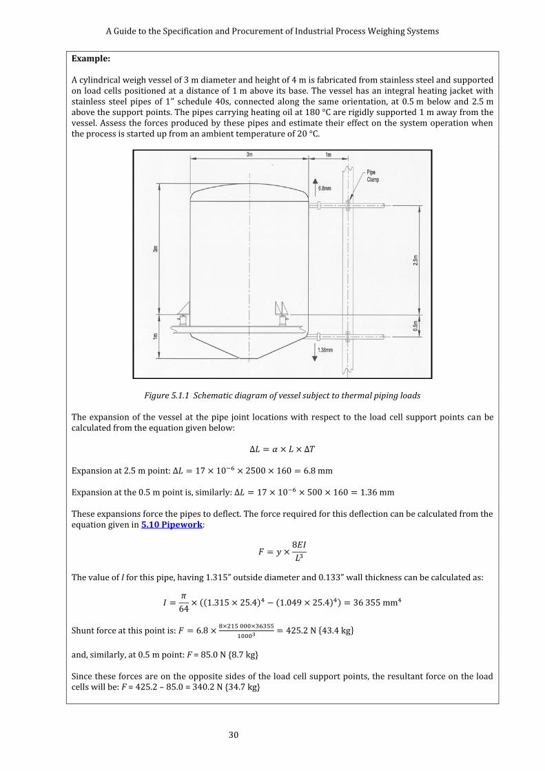
Example: A cylindrical weigh vessel of 3 m diameter and height of 4 m is fabricated from stainless steel and supported on load cells positioned at a distance of 1 m above its base. The vessel has an integral heating jacket with stainless steel pipes of 1” schedule 40s, connected along the same orientation, at 0.5 m below and 2.5 m above the support points. The pipes carrying heating oil at 180 °C are rigidly supported 1 m away from the vessel. Assess the forces produced by these pipes and estimate their effect on the system operation when the process is started up from an ambient temperature of 20 °C.
Figure 5.1.1 Schematic diagram of vessel subject to thermal piping loads The expansion of the vessel at the pipe joint locations with respect to the load cell support points can be calculated from the equation given below:
Expansion at 2.5 m point: Expansion at the 0.5 m point is, similarly: These expansions force the pipes to deflect. The force required for this deflection can be calculated from the equation given in 5.10 Pipework:
The value of I for this pipe, having 1.315” outside diameter and 0.133” wall thickness can be calculated as:
(( ) ( ) )
Shunt force at this point is:
{ }
and, similarly, at 0.5 m point: F = 85.0 N {8.7 kg} Since these forces are on the opposite sides of the load cell support points, the resultant force on the load cells will be: F = 425.2 – 85.0 = 340.2 N {34.7 kg}

A Guide to the Specification and Procurement of Industrial Process Weighing Systems
31
This force will act as constant output error for 160 °C temperature rise. It is also possible to calculate the horizontal forces generated by thermal stresses:
{ }
The vessel diameter will also increase by 8 mm. It is advisable to incorporate some means of free motion device in this system to avoid setting up thermal stresses.
5.1.3 Mounting hardware In process weighing applications load cells are normally used with a suitable mounting kit to facilitate the correct application of load to the load cell. Such kits can help to protect the load cell from damaging loads and may provide a jacking facility. This hardware is generally designed to allow limited movement of structures to reduce the errors produced by thermal expansions. In cases where this movement is relatively large, typically in excess of 5 mm, a specially designed unit, sometimes referred to as a Free Motion Unit (FMU), is utilised. A free motion unit is a mechanical arrangement which allows the weigh structure to expand without exerting damaging forces on the load cell. These units may be omni-directional (i.e. the expansion can take place in all directions) or bi-directional (i.e. the expansion is allowed only along one axis). This is usually achieved by incorporating a low-friction element between the load cell and the load receiving element. There are other types of mounting hardware utilised in the installation of weighing systems; and this hardware may act as a force shunt and contribute to the weighing system output as the temperature changes. The most significant of these are tie bars or stay rods. The tie bars may have a significant error contribution to the system output if their temperature changes independently of the rest of the mechanical structure. Other mounting hardware which may act as permanent force shunts (e.g. tension wires or bridge bearings) or that may become force shunts under certain operating conditions (e.g. check rods and bump stops) needs to be considered for their possible effects on the system output. 5.1.4 Load bearing structure It is unusual for the load bearing structure to change its temperature relative to the rest of the weighing structure. In cases where this takes place the considerations will be similar to those in 5.1.1 Load receiving element. 5.1.5 Junction box and cable Most junction boxes are field mounted and mainly contain terminal blocks. They may incorporate fixed or adjustable resistors or electronic circuitry. The main purpose of the junction box is to facilitate the connection of cables from the load cell(s) to the weighing instrumentation. In the case of simple junction boxes containing terminal blocks only, the influence of temperature is negligible. Where the junction box incorporates electrical or electronic components then the manufacturer’s specification should be consulted to establish the temperature effects. In four-wire excitation systems, the cable between the junction box and the weighing instrumentation can contribute significant errors caused by its change of resistance due to temperature variations. The extent of this error depends on the number of load cells in the system, type of system cable, its length and the range of temperature variation. The following expression gives the voltage drop, Vd, across the cores of the cable carrying the excitation voltage:
where: RC is the total resistance of the cores carrying the excitation voltage, RL is the combined resistance of load cells as seen from the junction box, Vexc is the load cell excitation voltage at the weighing instrumentation.

A Guide to the Specification and Procurement of Industrial Process Weighing Systems
32
This permanent voltage drop reduces the effective excitation voltage applied to the load cells and it is also temperature dependent. The change of this voltage with temperature Vd can be calculated from the following expression:
where: is the temperature coefficient of the cable conductor material (for copper, 4 000 × 10-6 Ω·Ω-1·°C-1)
ΔT is the change of temperature from the reference temperature.
Conductor Area, / mm2
Typical Strand Arrangement
Resistance, ·km-1
0.5 16/0.2 mm, 28/0.15 mm 40
0.75 24/0.2 mm 30
1.0 32/0.2 mm 20
1.5 30/0.25 mm 13.3
Table 5.1.3 Typical resistance of commonly used system cables.
Example: A silo weighing system is installed outdoors on four 350 Ω load cells connected in parallel in the junction box. The weight indicator working on a four-wire system is located in the control room, which is 100 m away from the junction box and provides 10 V dc excitation. The system cable used is a four-core screened cable with each core of 16 strands of 0.2 mm diameter, and the complete cable length is subjected to a 20 °C temperature change during a 24 hour period.
The voltage drop along the 100 m system cable is:
⁄
The weighing system output error due to the temperature change can be computed from the following expression, giving the error ε as a percentage in the weighing system output due to temperature change of ΔT:
(
( )
)
Substituting the values given in this equation we obtain the error:
(
( ) )
That is, as the temperature increases by 20 °C, the weighing system output is reduced by 0.675 %.
5.1.6 Weighing instrumentation When these units are placed in control rooms they are subjected to a limited range of temperature changes compared to the rest of the weighing system components. In applications where these units, sometimes referred as blind amplifiers, transmitters, etc, are placed outdoors, they are subjected to similar temperature variations to that of the load cells. The manufacturer’s specification should be consulted in order to establish the temperature effects on the system output.
It is normal practice to use 6-wire systems in the weighing instrumentation for excitation of the load cells. This method uses a technique of sensing the voltage drop along the cable supplying the load cells and correcting for it.
The following should be considered:
1. When the zero tracking is activated, slow variations at zero load indication (such as due to temperature changes) will be nullified.
2. If the weighing instrumentation has a 4-wire system, the effect of the temperature changes on the system

A Guide to the Specification and Procurement of Industrial Process Weighing Systems
33
cable should be determined and its effect on the system output should be computed. 3. If the weighing instrumentation has a 6-wire system, the limits of compensation for the voltage drop along
the excitation lines should be determined. 4. If safety barriers are used, their location and the temperatures they are likely to be subjected to should be
specified. The temperature effects of these barriers should be calculated from the manufacturer’s specifications.
5.2 ATMOSPHERIC QUALITY Whenever reference is made to atmospheric quality in this sub-section, our definition takes a broader view than that of the meteorologist. Consideration is given to the atmosphere, including effects on its composition contributed by the process surrounding the various elements of the weighing system. The main effects of atmospheric quality may be listed as: 1. Corrosion, which can also occur due to materials used in cleaning the plant (see 4.6 Cleaning And Hygiene). 2. Abrasion, due to powders and dusts. 3. Force shunting, due to solid contaminant build-up. It should also be noted that the effect of moisture on
some dusts and powders could produce incompressible material. 4. Accumulation of solid contaminants causing zero load output error. Corrosion is used here to describe the partial or complete wearing away, dissolving or softening of any substance by a chemical or electrochemical reaction. The term is applied here to the gradual action of chemicals, contained in the environment surrounding the weighing system, on metals and other materials used in construction. The most common and familiar example is the rusting of iron and steel due to the action of oxygen and water, both being necessary for the reaction to occur. The corrosion process can be accelerated by a number of factors including the presence of other chemicals, electrochemical action between dissimilar metals, temperature and mechanical stress. Plastics used in the weighing system can also be vulnerable to attack by chemicals, notably solvents; and apparently inert materials like glass and concrete may also be affected in certain circumstances. When specifying materials, consideration should be given to the distinction between effects which may cause deterioration in performance and those which are aesthetic in nature. The degree of corrosion is dependent upon factors such as temperature, pressure, concentration of solution, the presence of other chemicals and the duration of exposure. It is suggested that specialist advice should be sought to establish the suitability of a material for a particular use. Abrasion typically occurs in plants where powders are present, such as glass processing or in desert areas subject to sandstorms. It should be borne in mind that the effect of moisture in the atmosphere on some dusts and powders can produce a incompressible solid which may influence the transfer of load from the load receptor to the load bearing structure. The effect of dust should be considered carefully as it may accumulate on the load receiving element and affect the zero load output of the weighing system. The onus for advising the weighing equipment supplier, via the specification, of the hazards in the atmospheric quality must be placed upon the end user of the equipment, either directly or through an intermediate contractor. 5.2.1 Load receiving element The load receiving element can generally be protected from the effects of corrosion and abrasion by the use of carefully selected construction materials and/or surface coatings. Consideration should be given to mechanical design to reduce the external material build-up. 5.2.2 Load cell Careful selection of the materials of construction of the load cell and the method of sealing can contribute greatly to the load cell’s long-term reliability in a corrosive atmosphere. Typically such corrosion can have two effects on the load cell performance: premature mechanical failure due to deterioration of its metallurgical properties; electrical instability or failure due to contaminant ingress. Load cells are typically manufactured from stainless steel, alloy steel or aluminium. They may additionally be coated, plated or painted. It is widely accepted that fully welded stainless steel load cells provide the optimum
A Guide to the Specification and Procurement of Industrial Process Weighing Systems
34
degree of protection against the effects of the most corrosive materials. However, under certain circumstances, materials such as chlorine and chlorine-based products will affect some stainless steels, notably by stress corrosion cracking. Note that austenitic stainless steels such as AISI 316 are not generally suitable for the manufacture of high-performance load cells. A common grade of stainless steel used for load cell manufacture is 17-4 PH. Careful consideration must also be given to peripheral components such as the cable gland, plug, sockets, and cabling. This may be a particular problem in the presence of solvents. 5.2.3 Mounting hardware The mounting hardware components are required to move sufficiently to accommodate operational structural movements. Corrosion, abrasion and the coagulation of wet powders can all impede these movements. Furthermore, overload and jacking devices can deteriorate in the presence of any of these three factors and can subsequently fail to function correctly. Consideration should be given to provide independent and maintainable methods of providing overload protection and jacking facilities. Fasteners used in the assembly of the load cell and its mounting hardware must be of appropriate material and grade. Any grease or lubricants used in the assembly should be compatible with the application environment. Excessive use of such materials can be counter-productive due to coagulation with contaminants. Use of proprietary dry lubricants may be preferable under these conditions. Use of gaiters or boots should also be considered. 5.2.4 Load bearing structure Comments in section 5.2.1 Load receiving element apply. Special attention may also need to be given to any supporting concrete structure for protection from corrosion and abrasion. 5.2.5 Junction box There are two considerations for selecting the junction box:
material construction, metallic or non-metallic;
sealing level (see 5.3 Humidity). 5.2.6 Weighing instrumentation The considerations given to the enclosure used in 5.2.5 Junction box apply equally to the enclosures used for housing the weighing instrumentation.
5.3 HUMIDITY This subsection addresses the effects of humidity on the weighing system. The main effects of humidity may be listed as:
changes in the weight of the load receiving element due to condensing water; changes in the weight of the product being weighed due to water absorption; changes to the electrical characteristics of the weighing system due to contamination by water and any
dissolved chemicals it may contain; increased corrosion effects (see 5.2 Atmospheric quality); changes in the buoyancy effects of displaced air acting on the load receiving element.
Humidity denotes the amount of water vapour in the atmosphere. The absolute humidity is defined as the mass of water vapour per unit volume of atmosphere; however, a more useful quantity is Relative Humidity (RH).
In order to understand the definition of relative humidity, it has to be appreciated that the total pressure of the atmosphere is the sum of the partial pressures of each of its component gases, of which water vapour is one. The partial pressure of water vapour in the atmosphere cannot, except in very unusual cases, exceed the vapour pressure of water. When this condition is met, the atmosphere is said to be saturated and liquid water is formed as condensation. Relative humidity is defined as the ratio of the partial pressure of water actually present in the atmosphere to the saturated vapour pressure of water at the same temperature. The RH of a saturated atmosphere is therefore 100 %.
When the atmosphere cools, notably at night, the rate of cooling can exceed the rate at which water vapour can be lost. The relative humidity therefore rises and at some point may reach 100 %, at which time condensation will occur. This temperature is known as the Dew Point.

A Guide to the Specification and Procurement of Industrial Process Weighing Systems
35
The specification should provide a quantitative indication of the likely level and duration of any relevant humidity levels present. Where not known, reference to the geography and environment of the proposed installation may be helpful.
5.3.1 Load receiving element When the atmosphere becomes saturated, water will condense and can lay on the load receiving element, giving rise to an apparent product weight increase.
Example: A silo with a flat top measuring 5 m in diameter is sited outside in air at 15 °C and RH = 50 %. The following table shows the vapour pressure (VP) of water at various temperatures:
Temp / °C VP / bar Temp / °C VP / bar Temp / °C VP / bar
0 0.006 20 0.023 40 0.074
5 0.009 25 0.032 45 0.096
10 0.012 30 0.042 50 0.124
15 0.017 35 0.056 55 0.158
Table 5.3.1 Relationship between the temperature and vapour pressure.
From the table the partial pressure of the water vapour is: 0.017 × 50 % = 0.008 5 bar As the air temperature drops to about 5 °C, assuming no change in the amount of water present, it can be seen that this partial pressure becomes equal to the vapour pressure of water and condensation will occur. Water will be deposited on the silo, and if a film of depth 1 mm accumulates on the top surface this could amount to approximately 20 kg. It should be noted that condensation may also be present on other surfaces, increasing the effect.
The absorption of water by weighed product will lead to an increase of weight. It is debatable whether this is an error, as the weight of the material has genuinely increased. The system output does not, however, represent the dry weight and care has to be taken if the latter is the quantity that is required.
Air buoyancy errors due to humidity changes affecting the density of air do exist, but are considered negligible in industrial process weighing systems. 5.3.2 Load cell In a load cell the electrical connections are relatively close to each other and to the metallic structure of the transducer, requiring the maintenance of very high insulation resistances for satisfactory performance. The electrical shunting effects of water can be significant. Furthermore, deposits of dissolved chemicals can cause problems which persist beyond the time when the water has dried out. Sealing of the load cell therefore demands particular consideration.
The points of entry for water vapour are primarily the seals of the strain gauge housing and the connecting cable entry.
The strain gauge enclosure on the load cell can be sealed by either potting the system, or by welding or otherwise fixing a cover over the arrangement. A feature of potted systems is that if the potting material does not completely adhere to the metal of the load cell, very small gaps can be formed. Through the process of capillary action, these small gaps can cause significant problems.
Cables do not normally present a major problem unless the integrity of the sheath is breached. This may be due to mechanical (including animal) or chemical attack, permitting moisture to enter. This may cause short-circuits either directly in the cable or indirectly by allowing the moisture to be channelled by capillary action to the interior of the load cell. In extreme circumstances, water can even travel the whole length of a cable by capillary action.
A Guide to the Specification and Procurement of Industrial Process Weighing Systems
36
Specification of the degree of sealing can be made with reference to the IP code [9] (see also 7.2 Summary of IP codes based on BS EN 60529). This code addresses the protection of electrical enclosures in general and is dealt with in 5.3.5 Junction box. OIML Recommendation R 60 for the Metrological Regulation of Load Cells [10] includes provision for determining the effects of humidity by performing a damp heat, cyclic test in accordance with IEC 60068-2-30 [20]. The magnitude of humidity-induced variations is determined and compared with specified limits. 5.3.3 Mounting hardware Effects considered not applicable, other than the obvious implications of possible corrosion.
5.3.4 Load bearing structure Effects considered not applicable, other than the obvious implications of possible corrosion.
5.3.5 Junction box The junction box sealing integrity could ideally be specified with reference to the damp heat codes, but where this data is not available the IP code is useful. The IP code [9] provides a specification for the degree of protection provided by enclosures of electrical equipment. This data is summarised in 7.2 Summary of IP codes based on BS EN 60529.
In addition to defining the degree of protection to persons from hazardous parts in the enclosure and the degree of protection of equipment in the enclosure to solid foreign objects, the code does specify the protection of the equipment against harmful effects due to the ingress of water. It therefore has some limited relevance to the effect of humidity - particularly if condensation may occur. The part of the IP code number relevant to the ingress of water is the second numeral. Numbers 0 to 6 inclusive are associated with protection against dripping or jetting water and are not particularly relevant to the effects of humidity.
Number 7 (IPx7) indicates that the ingress of water in quantities causing harmful effects should not be possible when the enclosure is temporarily immersed in water under standard conditions of pressure (at a depth of 0.15 m to 1.0 m) and time (30 minutes). Number 8 (IPx8) indicates that the ingress of water in quantities causing harmful effects shall not be possible when the enclosure is continuously immersed. The exact conditions shall be agreed between the manufacturer and the user but shall be more severe than those for number 7. The conditions shall take into account that the enclosure may be continuously immersed in actual use. Included in the acceptance conditions for water ingress tests is that if any water has entered it shall neither be sufficient to interfere with the correct operation of the equipment nor deposit on insulating parts where it could lead to tracking. It should be noted that a particular classification number does not necessarily imply that the enclosure would pass tests for a lower classification unless it has been subject to those tests. With regard to protection against humidity, as number 7 only refers to immersion for 30 minutes it is of very limited relevance. It may be argued that number 8 may signify that the system would be immune to the effects of water vapour. However, as the conditions are subject to agreement between the manufacturer and the user, factors such as immersion time would need to be considered. The sealing of a proprietary junction box may be compromised by poor cable entry glands, and where used these glands must also have the appropriate level of sealing.
5.3.6 Weighing instrumentation Where the weighing instrumentation may be affected by humid atmosphere, the considerations in 5.3.5 Junction box apply. Modern surface mount technology can potentially exacerbate these problems due to the close proximity of components and tracks. It is possible to apply a conformal coating to protect the circuit from the effects of humidity and pollution.
5.4 PRECIPITATION In this subsection the effects of precipitation on the weighing system are considered. Precipitation is taken to encompass rain, snow and hail, and the effects considered to be significant are:
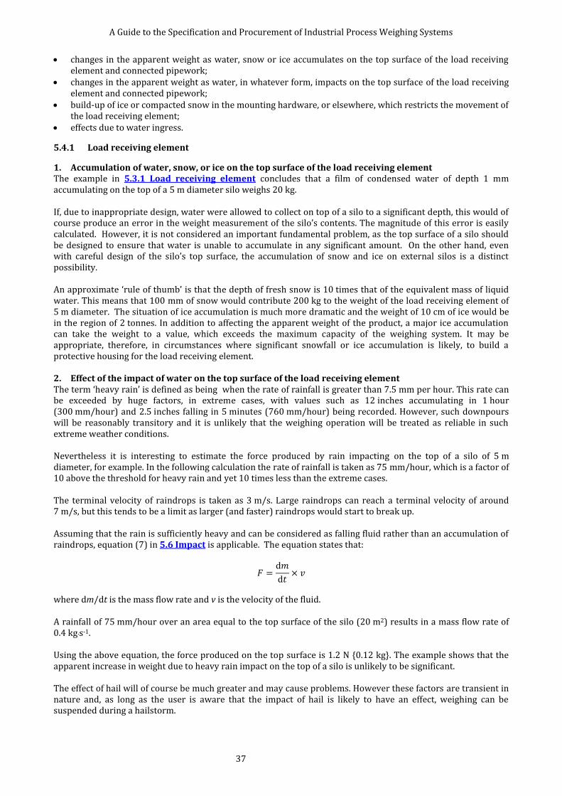
A Guide to the Specification and Procurement of Industrial Process Weighing Systems
37
changes in the apparent weight as water, snow or ice accumulates on the top surface of the load receiving element and connected pipework;
changes in the apparent weight as water, in whatever form, impacts on the top surface of the load receiving element and connected pipework;
build-up of ice or compacted snow in the mounting hardware, or elsewhere, which restricts the movement of the load receiving element;
effects due to water ingress.
5.4.1 Load receiving element
1. Accumulation of water, snow, or ice on the top surface of the load receiving element The example in 5.3.1 Load receiving element concludes that a film of condensed water of depth 1 mm accumulating on the top of a 5 m diameter silo weighs 20 kg. If, due to inappropriate design, water were allowed to collect on top of a silo to a significant depth, this would of course produce an error in the weight measurement of the silo’s contents. The magnitude of this error is easily calculated. However, it is not considered an important fundamental problem, as the top surface of a silo should be designed to ensure that water is unable to accumulate in any significant amount. On the other hand, even with careful design of the silo’s top surface, the accumulation of snow and ice on external silos is a distinct possibility. An approximate ‘rule of thumb’ is that the depth of fresh snow is 10 times that of the equivalent mass of liquid water. This means that 100 mm of snow would contribute 200 kg to the weight of the load receiving element of 5 m diameter. The situation of ice accumulation is much more dramatic and the weight of 10 cm of ice would be in the region of 2 tonnes. In addition to affecting the apparent weight of the product, a major ice accumulation can take the weight to a value, which exceeds the maximum capacity of the weighing system. It may be appropriate, therefore, in circumstances where significant snowfall or ice accumulation is likely, to build a protective housing for the load receiving element. 2. Effect of the impact of water on the top surface of the load receiving element The term ‘heavy rain’ is defined as being when the rate of rainfall is greater than 7.5 mm per hour. This rate can be exceeded by huge factors, in extreme cases, with values such as 12 inches accumulating in 1 hour (300 mm/hour) and 2.5 inches falling in 5 minutes (760 mm/hour) being recorded. However, such downpours will be reasonably transitory and it is unlikely that the weighing operation will be treated as reliable in such extreme weather conditions. Nevertheless it is interesting to estimate the force produced by rain impacting on the top of a silo of 5 m diameter, for example. In the following calculation the rate of rainfall is taken as 75 mm/hour, which is a factor of 10 above the threshold for heavy rain and yet 10 times less than the extreme cases. The terminal velocity of raindrops is taken as 3 m/s. Large raindrops can reach a terminal velocity of around 7 m/s, but this tends to be a limit as larger (and faster) raindrops would start to break up. Assuming that the rain is sufficiently heavy and can be considered as falling fluid rather than an accumulation of raindrops, equation (7) in 5.6 Impact is applicable. The equation states that:
where dm/dt is the mass flow rate and v is the velocity of the fluid. A rainfall of 75 mm/hour over an area equal to the top surface of the silo (20 m2) results in a mass flow rate of 0.4 kg·s-1. Using the above equation, the force produced on the top surface is 1.2 N {0.12 kg}. The example shows that the apparent increase in weight due to heavy rain impact on the top of a silo is unlikely to be significant. The effect of hail will of course be much greater and may cause problems. However these factors are transient in nature and, as long as the user is aware that the impact of hail is likely to have an effect, weighing can be suspended during a hailstorm.
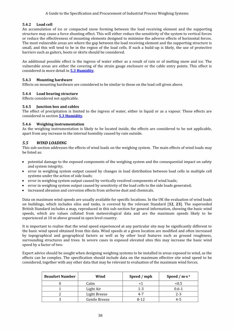
A Guide to the Specification and Procurement of Industrial Process Weighing Systems
38
5.4.2 Load cell An accumulation of ice or compacted snow forming between the load receiving element and the supporting structure may cause a force shunting effect. This will either reduce the sensitivity of the system to vertical forces or reduce the effectiveness of mounting elements designed to minimise the adverse effects of horizontal forces. The most vulnerable areas are where the gap between the load receiving element and the supporting structure is small, and this will tend to be in the region of the load cells. If such a build-up is likely, the use of protective barriers such as gaiters, boots or skirts should be considered. An additional possible effect is the ingress of water either as a result of rain or of melting snow and ice. The vulnerable areas are either the covering of the strain gauge enclosure or the cable entry points. This effect is considered in more detail in 5.3 Humidity. 5.4.3 Mounting hardware Effects on mounting hardware are considered to be similar to those on the load cell given above. 5.4.4 Load bearing structure Effects considered not applicable.
5.4.5 Junction box and cables The effect of precipitation is limited to the ingress of water, either in liquid or as a vapour. These effects are considered in section 5.3 Humidity.
5.4.6 Weighing instrumentation As the weighing instrumentation is likely to be located inside, the effects are considered to be not applicable, apart from any increase in the internal humidity caused by rain outside.
5.5 WIND LOADING This sub-section addresses the effects of wind loads on the weighing system. The main effects of wind loads may be listed as: potential damage to the exposed components of the weighing system and the consequential impact on safety
and system integrity; error in weighing system output caused by changes in load distribution between load cells in multiple cell
systems under the action of side loads; error in weighing system output caused by vertically resolved components of wind loads; error in weighing system output caused by sensitivity of the load cells to the side loads generated; increased abrasion and corrosion effects from airborne dust and chemicals. Data on maximum wind speeds are usually available for specific locations. In the UK the evaluation of wind loads on buildings, which includes silos and tanks, is covered by the relevant Standard [12, 23]. The superseded British Standard includes a map, reproduced in this sub-section for general information, showing the basic wind speeds, which are values collated from meteorological data and are the maximum speeds likely to be experienced at 10 m above ground in open level country.
It is important to realise that the wind speed experienced at any particular site may be significantly different to the basic wind speed obtained from this data. Wind speeds at a given location are modified and often increased by topographical and geographical factors as well as by other local features such as ground roughness, surrounding structures and trees. In severe cases in exposed elevated sites this may increase the basic wind speed by a factor of two.
Expert advice should be sought when designing weighing systems to be installed in areas exposed to wind, as the effects can be complex. The specification should include data on the maximum effective site wind speed to be considered, together with any other data that may be relevant to evaluation of the maximum wind forces.
Beaufort Number Wind Speed / mph Speed / m·s-1
0 Calm <1 <0.5
1 Light Air 1-3 0.6-1
2 Light Breeze 4-7 2-3
3 Gentle Breeze 8-12 4-5
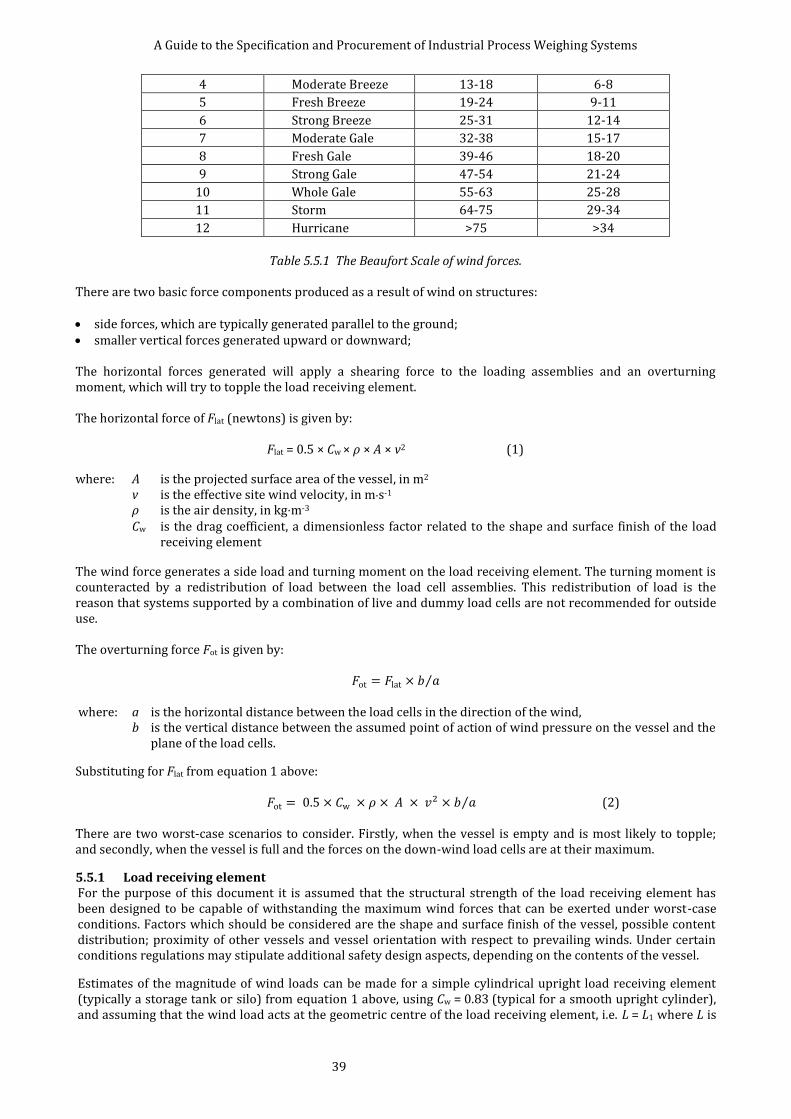
A Guide to the Specification and Procurement of Industrial Process Weighing Systems
39
4 Moderate Breeze 13-18 6-8
5 Fresh Breeze 19-24 9-11
6 Strong Breeze 25-31 12-14
7 Moderate Gale 32-38 15-17
8 Fresh Gale 39-46 18-20
9 Strong Gale 47-54 21-24
10 Whole Gale 55-63 25-28
11 Storm 64-75 29-34
12 Hurricane >75 >34
Table 5.5.1 The Beaufort Scale of wind forces.
There are two basic force components produced as a result of wind on structures: side forces, which are typically generated parallel to the ground; smaller vertical forces generated upward or downward; The horizontal forces generated will apply a shearing force to the loading assemblies and an overturning moment, which will try to topple the load receiving element. The horizontal force of Flat (newtons) is given by:
Flat = 0.5 × Cw × ρ × A × v2 (1)
where: A is the projected surface area of the vessel, in m2 v is the effective site wind velocity, in m·s-1
ρ is the air density, in kg·m-3 Cw is the drag coefficient, a dimensionless factor related to the shape and surface finish of the load
receiving element
The wind force generates a side load and turning moment on the load receiving element. The turning moment is counteracted by a redistribution of load between the load cell assemblies. This redistribution of load is the reason that systems supported by a combination of live and dummy load cells are not recommended for outside use. The overturning force Fot is given by:
⁄ where: a is the horizontal distance between the load cells in the direction of the wind,
b is the vertical distance between the assumed point of action of wind pressure on the vessel and the plane of the load cells.
Substituting for Flat from equation 1 above:
⁄ (2) There are two worst-case scenarios to consider. Firstly, when the vessel is empty and is most likely to topple; and secondly, when the vessel is full and the forces on the down-wind load cells are at their maximum.
5.5.1 Load receiving element For the purpose of this document it is assumed that the structural strength of the load receiving element has been designed to be capable of withstanding the maximum wind forces that can be exerted under worst-case conditions. Factors which should be considered are the shape and surface finish of the vessel, possible content distribution; proximity of other vessels and vessel orientation with respect to prevailing winds. Under certain conditions regulations may stipulate additional safety design aspects, depending on the contents of the vessel.
Estimates of the magnitude of wind loads can be made for a simple cylindrical upright load receiving element (typically a storage tank or silo) from equation 1 above, using Cw = 0.83 (typical for a smooth upright cylinder), and assuming that the wind load acts at the geometric centre of the load receiving element, i.e. L = L1 where L is

A Guide to the Specification and Procurement of Industrial Process Weighing Systems
40
the distance between the plane of the load cells and the geometric centre of the vessel and L1 is the distance between the plane of the load cells and the centre of gravity of the vessel. a) For a 3 point supported vessel subject to a lateral wind load Flat acting at its centre of wind pressure (assumed here to be at the geometric centre of the vessel) and using the nomenclature in Figure 5.5.1:
in equivalent kg weight units.
Figure 5.5.1 Schematic representation of wind loads on a three-point supported vessel. Then, taking moments, the maximum load to be withstood by each load cell and its support is given using equation 2 above by:

A Guide to the Specification and Procurement of Industrial Process Weighing Systems
41
Example: A vessel, shown in Figure 5.5.1, having a dead load of 1 000 kg and a total gross weight of 8 000 kg is subject to a site wind speed of 40 ms-1. The overall dimensions of the vessel are given as height 9 m and diameter 3 m. The load supports must be able to withstand a load of:
It is of interest to note that, with the wind in the opposite direction, this vessel would overturn even when full unless overturning protection is provided and, when empty, would become unstable at a wind speed calculated from:
which gives v = 11 m·s-1
b) For a 4-point supported vessel subject to a lateral wind load Flat acting at its centre of wind pressure (assumed here to be at the geometric centre of the vessel) and using the nomenclature in figure 5.5.2:
in equivalent kg weight units. Then taking moments, the maximum load to be withstood by each load cell and its support is given using equation 2 above by:
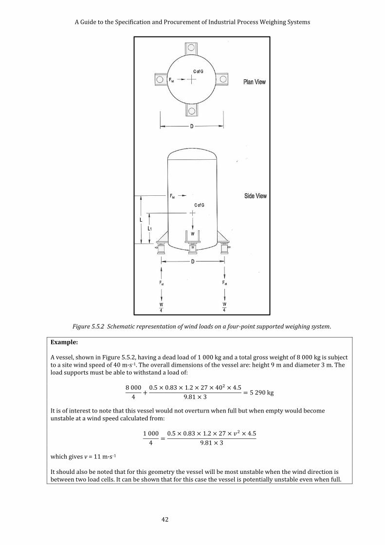
A Guide to the Specification and Procurement of Industrial Process Weighing Systems
42
Figure 5.5.2 Schematic representation of wind loads on a four-point supported weighing system.
Example: A vessel, shown in Figure 5.5.2, having a dead load of 1 000 kg and a total gross weight of 8 000 kg is subject to a site wind speed of 40 m·s-1. The overall dimensions of the vessel are: height 9 m and diameter 3 m. The load supports must be able to withstand a load of:
It is of interest to note that this vessel would not overturn when full but when empty would become unstable at a wind speed calculated from:
which gives v = 11 m·s-1
It should also be noted that for this geometry the vessel will be most unstable when the wind direction is between two load cells. It can be shown that for this case the vessel is potentially unstable even when full.
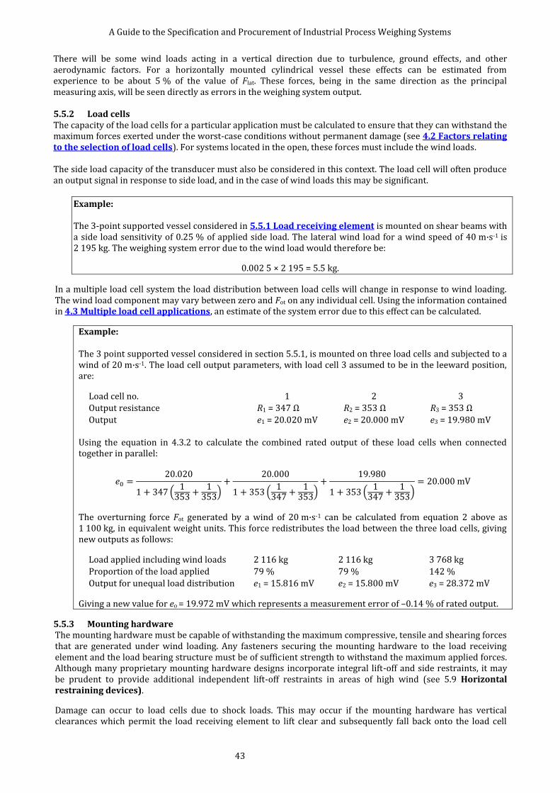
A Guide to the Specification and Procurement of Industrial Process Weighing Systems
43
There will be some wind loads acting in a vertical direction due to turbulence, ground effects, and other aerodynamic factors. For a horizontally mounted cylindrical vessel these effects can be estimated from experience to be about 5 % of the value of Flat. These forces, being in the same direction as the principal measuring axis, will be seen directly as errors in the weighing system output. 5.5.2 Load cells The capacity of the load cells for a particular application must be calculated to ensure that they can withstand the maximum forces exerted under the worst-case conditions without permanent damage (see 4.2 Factors relating to the selection of load cells). For systems located in the open, these forces must include the wind loads. The side load capacity of the transducer must also be considered in this context. The load cell will often produce an output signal in response to side load, and in the case of wind loads this may be significant.
Example: The 3-point supported vessel considered in 5.5.1 Load receiving element is mounted on shear beams with a side load sensitivity of 0.25 % of applied side load. The lateral wind load for a wind speed of 40 m·s-1 is 2 195 kg. The weighing system error due to the wind load would therefore be:
0.002 5 × 2 195 = 5.5 kg.
In a multiple load cell system the load distribution between load cells will change in response to wind loading. The wind load component may vary between zero and Fot on any individual cell. Using the information contained in 4.3 Multiple load cell applications, an estimate of the system error due to this effect can be calculated.
Example: The 3 point supported vessel considered in section 5.5.1, is mounted on three load cells and subjected to a wind of 20 m·s-1. The load cell output parameters, with load cell 3 assumed to be in the leeward position, are:
Load cell no. 1 2 3
Output resistance R1 = 347 Ω R2 = 353 Ω R3 = 353 Ω
Output e1 = 20.020 mV e2 = 20.000 mV e3 = 19.980 mV Using the equation in 4.3.2 to calculate the combined rated output of these load cells when connected together in parallel:
(
)
(
)
(
)
The overturning force Fot generated by a wind of 20 m·s-1 can be calculated from equation 2 above as 1 100 kg, in equivalent weight units. This force redistributes the load between the three load cells, giving new outputs as follows:
Load applied including wind loads 2 116 kg 2 116 kg 3 768 kg
Proportion of the load applied 79 % 79 % 142 %
Output for unequal load distribution e1 = 15.816 mV e2 = 15.800 mV e3 = 28.372 mV
Giving a new value for eo = 19.972 mV which represents a measurement error of –0.14 % of rated output.
5.5.3 Mounting hardware The mounting hardware must be capable of withstanding the maximum compressive, tensile and shearing forces that are generated under wind loading. Any fasteners securing the mounting hardware to the load receiving element and the load bearing structure must be of sufficient strength to withstand the maximum applied forces. Although many proprietary mounting hardware designs incorporate integral lift-off and side restraints, it may be prudent to provide additional independent lift-off restraints in areas of high wind (see 5.9 Horizontal restraining devices).
Damage can occur to load cells due to shock loads. This may occur if the mounting hardware has vertical clearances which permit the load receiving element to lift clear and subsequently fall back onto the load cell

A Guide to the Specification and Procurement of Industrial Process Weighing Systems
44
when subject to wind loads.
5.5.4 Load bearing structure For the purpose of this document it is assumed that the load bearing structure is capable of withstanding the maximum forces applied under worst-case conditions.
If load cells are being retrofitted to existing structures, it should be remembered that although the load receiving element may have had sufficient wind load integrity when fixed solidly to the ground or other structure, the act of unbolting the weighing structure to insert load cells can significantly affect this integrity.
5.5.5 Junction box Effects considered not applicable.
5.5.6 Weighing instrumentation Effects considered not applicable.
Figure 5.5.3 Basic wind speeds, in m·s-1, in the United Kingdom. This extract from BS 6399 : Part 2 : 1997 (now superseded by [12]), is reproduced with the permission of BSI
5.6 IMPACT This sub-section addresses the effect of impact or shock load on the weighing system. The impact loads
Note that actual site wind speed may be much higher than those indicated on this
map.
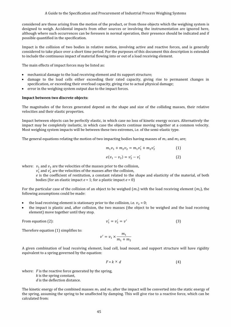
A Guide to the Specification and Procurement of Industrial Process Weighing Systems
45
considered are those arising from the motion of the product, or from those objects which the weighing system is designed to weigh. Accidental impacts from other sources or involving the instrumentation are ignored here, although where such occurrences can be foreseen in normal operation, their presence should be indicated and if possible quantified in the specification. Impact is the collision of two bodies in relative motion, involving active and reactive forces, and is generally considered to take place over a short time period. For the purposes of this document this description is extended to include the continuous impact of material flowing into or out of a load receiving element. The main effects of impact forces may be listed as: mechanical damage to the load receiving element and its support structure; damage to the load cells either exceeding their rated capacity, giving rise to permanent changes in
specification, or exceeding their overload capacity, giving rise to actual physical damage; error in the weighing system output due to the impact forces. Impact between two discrete objects: The magnitudes of the forces generated depend on the shape and size of the colliding masses, their relative velocities and their elastic properties. Impact between objects can be perfectly elastic, in which case no loss of kinetic energy occurs. Alternatively the impact may be completely inelastic, in which case the objects continue moving together at a common velocity. Most weighing system impacts will be between these two extremes, i.e. of the semi-elastic type. The general equations relating the motion of two impacting bodies having masses of m1 and m2 are;
(1)
( )
(2)
where: and are the velocities of the masses prior to the collision,
and are the velocities of the masses after the collision,
e is the coefficient of restitution, a constant related to the shape and elasticity of the material, of both bodies (for an elastic impact e = 1; for a plastic impact e = 0)
For the particular case of the collision of an object to be weighed (m1) with the load receiving element (m2), the following assumptions could be made: the load receiving element is stationary prior to the collision, i.e. = 0;
the impact is plastic and, after collision, the two masses (the object to be weighed and the load receiving element) move together until they stop.
From equation (2):
(3)
Therefore equation (1) simplifies to:
A given combination of load receiving element, load cell, load mount, and support structure will have rigidity equivalent to a spring governed by the equation:
F = k × d (4) where: F is the reactive force generated by the spring, k is the spring constant, d is the deflection distance. The kinetic energy of the combined masses m1 and m2 after the impact will be converted into the static energy of the spring, assuming the spring to be unaffected by damping. This will give rise to a reactive force, which can be calculated from:

A Guide to the Specification and Procurement of Industrial Process Weighing Systems
46
√ ( )⁄ (5)
Here the values of masses and the velocity of the weighed object at the time of impact need to be specified or determined for each case. In the case of the weighed object lowered on to the load receiving element, the speed of the operation would have to be specified. However, if the object is allowed to fall from a height of h on to the load receiving element then equation 5 becomes:
√ ( )⁄ (6)
The specification should state in as far as practicable the mass, shape, and elasticity of the impacting objects to enable the provider to assess the validity of the assumptions made in the above equations. Where data is not available, cannot be quantified, or is considered irrelevant, this should be stated. Extreme values of force can therefore result from impacts between stiff mechanical arrangements, possibly damaging the load cell either by plastic deformation or by strain gauge degradation due to shock waves – these forces can be reduced by the introduction of compliant fixtures, i.e. reducing k in equation (6). Continuous impact: For the consideration of continuous impact, the material flow will be assumed to behave like a non-viscous fluid. The general equation for the force F generated by fluid flow and caused by the rate of change of momentum is:
⁄ (7) where dm/dt is the mass flow rate and v is the velocity of the fluid.
This equation assumes that all the momentum is used to generate the force (i.e. the “worst” case).
For the inflow case, v is the velocity just prior to impact and can be calculated from the initial inflow velocity, u (if known), from:
⁄ √ (8)
where h is the height through which the material must fall. Equation 8 ignores the influence of air drag or other resistance, which might slow the fall.
For the outflow case, v is the exit velocity and can be calculated from Bernoulli’s general equation: ⁄ (9) where: ρ is the fluid density,
p is the pressure of the fluid, h is the static fluid head.
The specification should state the conditions and methods by which materials enter and leave the vessel in sufficient detail to permit the dynamic errors described above to be estimated. Where data is not available, cannot be quantified or is considered irrelevant, this should be stated. 5.6.1 Load receiving element The load receiving element should be constructed such that the maximum impact force, F, does not cause unacceptable long term damage. The parameters associated with the design and construction are clearly variable and can only be assessed on an individual basis. Consideration should also be given in design to the reduction of measurement error caused by momentum changes of the material entering or leaving the load receiving element, or to ensuring that some or all of the reaction forces set up are vectored in the least-sensitive load measuring direction.
Example A: To determine the maximum velocity at which the rated load can be lowered onto the scale without causing irreversible damage to the load cells.
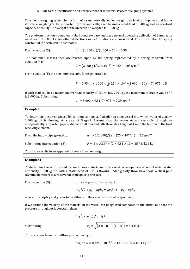
A Guide to the Specification and Procurement of Industrial Process Weighing Systems
47
Consider a weighing system in the form of a symmetrically loaded weigh scale having a top deck and frame structure weighing 50 kg supported by four load cells, each having a rated load of 500 kg and an overload capacity of 750 kg. The weight of the object to be weighed is 1 000 kg. The platform is set on a completely rigid concrete base and has a normal operating deflection of 3 mm at its rated load of 2 000 kg. No other deflections or deformations are considered. From this data, the spring constant of the scale can be estimated. From equation (3):
( ) ( ) ⁄ The combined masses then are reacted upon by the spring represented by a spring constant, from equation (4):
( ) ( )⁄
From equation (5) the maximum reactive force generated is:
√( ) ( )⁄
If each load cell has a maximum overload capacity of 150 % (i.e. 750 kg), the maximum tolerable value of F is 3 000 kg. Substituting:
⁄
Example B: To determine the error caused by continuous impact. Consider an open vessel into which water of density 1 000 kg·m-3 is flowing at a rate of 5 kg·s-1. Assume that the water enters vertically through an independently supported pipe of diameter 50 mm and falls through a height of 1 m to the bottom of the load receiving element. From the inflow pipe geometry: ( ⁄ ) ( ( ) )⁄
Substituting into equation (8): √ ( ) { } This force results in an apparent increase in vessel weight.
Example C: To determine the error caused by continuous material outflow. Consider an open vessel out of which water of density 1 000 kg·m-3 with a static head of 1 m is flowing under gravity through a short vertical pipe (50 mm diameter) to a receiver at atmospheric pressure. From equation (9): ⁄
⁄ ⁄
where subscripts 1 and 2 refer to conditions in the vessel and outlet respectively. If we assume the velocity of the material in the vessel can be ignored compared to the outlet, and that the pressure throughout is constant, then:
⁄ ( )
Substituting: √( ( ))
The mass flow from the outflow pipe geometry is:
⁄ ( )
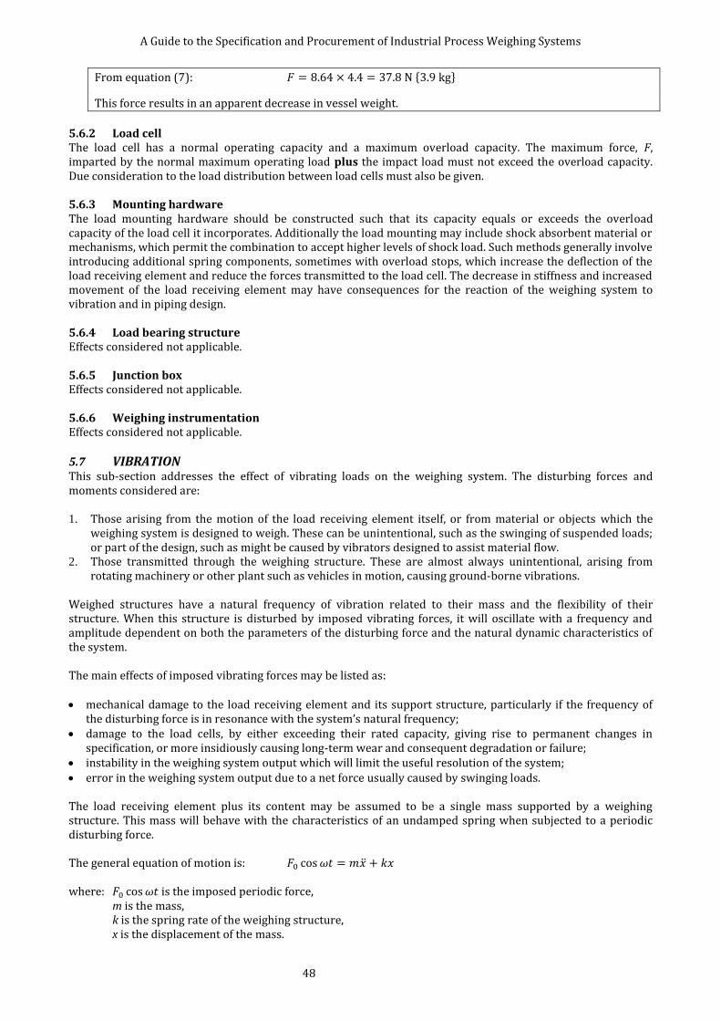
A Guide to the Specification and Procurement of Industrial Process Weighing Systems
48
From equation (7): { }
This force results in an apparent decrease in vessel weight.
5.6.2 Load cell The load cell has a normal operating capacity and a maximum overload capacity. The maximum force, F, imparted by the normal maximum operating load plus the impact load must not exceed the overload capacity. Due consideration to the load distribution between load cells must also be given. 5.6.3 Mounting hardware The load mounting hardware should be constructed such that its capacity equals or exceeds the overload capacity of the load cell it incorporates. Additionally the load mounting may include shock absorbent material or mechanisms, which permit the combination to accept higher levels of shock load. Such methods generally involve introducing additional spring components, sometimes with overload stops, which increase the deflection of the load receiving element and reduce the forces transmitted to the load cell. The decrease in stiffness and increased movement of the load receiving element may have consequences for the reaction of the weighing system to vibration and in piping design. 5.6.4 Load bearing structure Effects considered not applicable. 5.6.5 Junction box Effects considered not applicable. 5.6.6 Weighing instrumentation Effects considered not applicable.
5.7 VIBRATION This sub-section addresses the effect of vibrating loads on the weighing system. The disturbing forces and moments considered are: 1. Those arising from the motion of the load receiving element itself, or from material or objects which the
weighing system is designed to weigh. These can be unintentional, such as the swinging of suspended loads; or part of the design, such as might be caused by vibrators designed to assist material flow.
2. Those transmitted through the weighing structure. These are almost always unintentional, arising from rotating machinery or other plant such as vehicles in motion, causing ground-borne vibrations.
Weighed structures have a natural frequency of vibration related to their mass and the flexibility of their structure. When this structure is disturbed by imposed vibrating forces, it will oscillate with a frequency and amplitude dependent on both the parameters of the disturbing force and the natural dynamic characteristics of the system. The main effects of imposed vibrating forces may be listed as: mechanical damage to the load receiving element and its support structure, particularly if the frequency of
the disturbing force is in resonance with the system’s natural frequency; damage to the load cells, by either exceeding their rated capacity, giving rise to permanent changes in
specification, or more insidiously causing long-term wear and consequent degradation or failure; instability in the weighing system output which will limit the useful resolution of the system; error in the weighing system output due to a net force usually caused by swinging loads. The load receiving element plus its content may be assumed to be a single mass supported by a weighing structure. This mass will behave with the characteristics of an undamped spring when subjected to a periodic disturbing force. The general equation of motion is: ̈ where: is the imposed periodic force,
m is the mass, k is the spring rate of the weighing structure, x is the displacement of the mass.
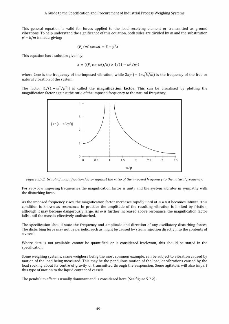
A Guide to the Specification and Procurement of Industrial Process Weighing Systems
49
This general equation is valid for forces applied to the load receiving element or transmitted as ground vibrations. To help understand the significance of this equation, both sides are divided by m and the substitution p2 = k/m is made, giving: ( ⁄ ) ̈ This equation has a solution given by: (( ) ⁄ ) ( ⁄ )⁄
where is the frequency of the imposed vibration, while ( √ ⁄ ) is the frequency of the free or natural vibration of the system. The factor | ( ⁄ )⁄ | is called the magnification factor. This can be visualised by plotting the magnification factor against the ratio of the imposed frequency to the natural frequency.
Figure 5.7.1 Graph of magnification factor against the ratio of the imposed frequency to the natural frequency. For very low imposing frequencies the magnification factor is unity and the system vibrates in sympathy with the disturbing force. As the imposed frequency rises, the magnification factor increases rapidly until at = p it becomes infinite. This condition is known as resonance. In practice the amplitude of the resulting vibration is limited by friction, although it may become dangerously large. As is further increased above resonance, the magnification factor falls until the mass is effectively undisturbed. The specification should state the frequency and amplitude and direction of any oscillatory disturbing forces. The disturbing force may not be periodic, such as might be caused by steam injection directly into the contents of a vessel. Where data is not available, cannot be quantified, or is considered irrelevant, this should be stated in the specification. Some weighing systems, crane weighers being the most common example, can be subject to vibration caused by motion of the load being measured. This may be the pendulous motion of the load, or vibrations caused by the load rocking about its centre of gravity or transmitted through the suspension. Some agitators will also impart this type of motion to the liquid content of vessels. The pendulum effect is usually dominant and is considered here (See figure 5.7.2).
0
1
2
3
4
0 0.5 1 1.5 2 2.5 3 3.5
|1 ∕ (1 − 𝜔2∕𝑝2)|
𝜔 ∕ 𝑝
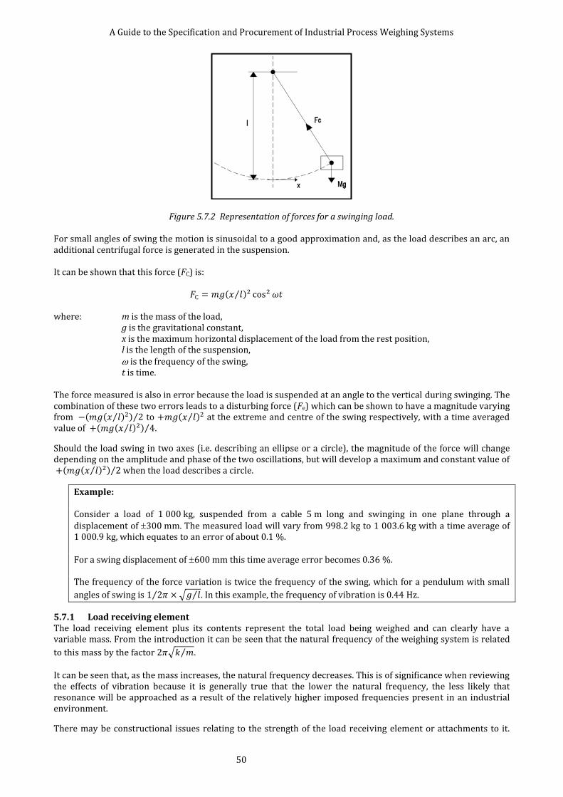
A Guide to the Specification and Procurement of Industrial Process Weighing Systems
50
Figure 5.7.2 Representation of forces for a swinging load. For small angles of swing the motion is sinusoidal to a good approximation and, as the load describes an arc, an additional centrifugal force is generated in the suspension. It can be shown that this force (FC) is: ( ⁄ ) where: m is the mass of the load, g is the gravitational constant, x is the maximum horizontal displacement of the load from the rest position, l is the length of the suspension, is the frequency of the swing, t is time. The force measured is also in error because the load is suspended at an angle to the vertical during swinging. The combination of these two errors leads to a disturbing force (Fe) which can be shown to have a magnitude varying from ( ( ⁄ ) ) ⁄ to ( ⁄ ) at the extreme and centre of the swing respectively, with a time averaged value of ( ( ⁄ ) ) ⁄ .
Should the load swing in two axes (i.e. describing an ellipse or a circle), the magnitude of the force will change depending on the amplitude and phase of the two oscillations, but will develop a maximum and constant value of ( ( ⁄ ) ) ⁄ when the load describes a circle.
Example: Consider a load of 1 000 kg, suspended from a cable 5 m long and swinging in one plane through a displacement of 300 mm. The measured load will vary from 998.2 kg to 1 003.6 kg with a time average of 1 000.9 kg, which equates to an error of about 0.1 %. For a swing displacement of 600 mm this time average error becomes 0.36 %. The frequency of the force variation is twice the frequency of the swing, which for a pendulum with small
angles of swing is ⁄ √ ⁄ . In this example, the frequency of vibration is 0.44 Hz.
5.7.1 Load receiving element The load receiving element plus its contents represent the total load being weighed and can clearly have a variable mass. From the introduction it can be seen that the natural frequency of the weighing system is related
to this mass by the factor √ ⁄ . It can be seen that, as the mass increases, the natural frequency decreases. This is of significance when reviewing the effects of vibration because it is generally true that the lower the natural frequency, the less likely that resonance will be approached as a result of the relatively higher imposed frequencies present in an industrial environment.
There may be constructional issues relating to the strength of the load receiving element or attachments to it.
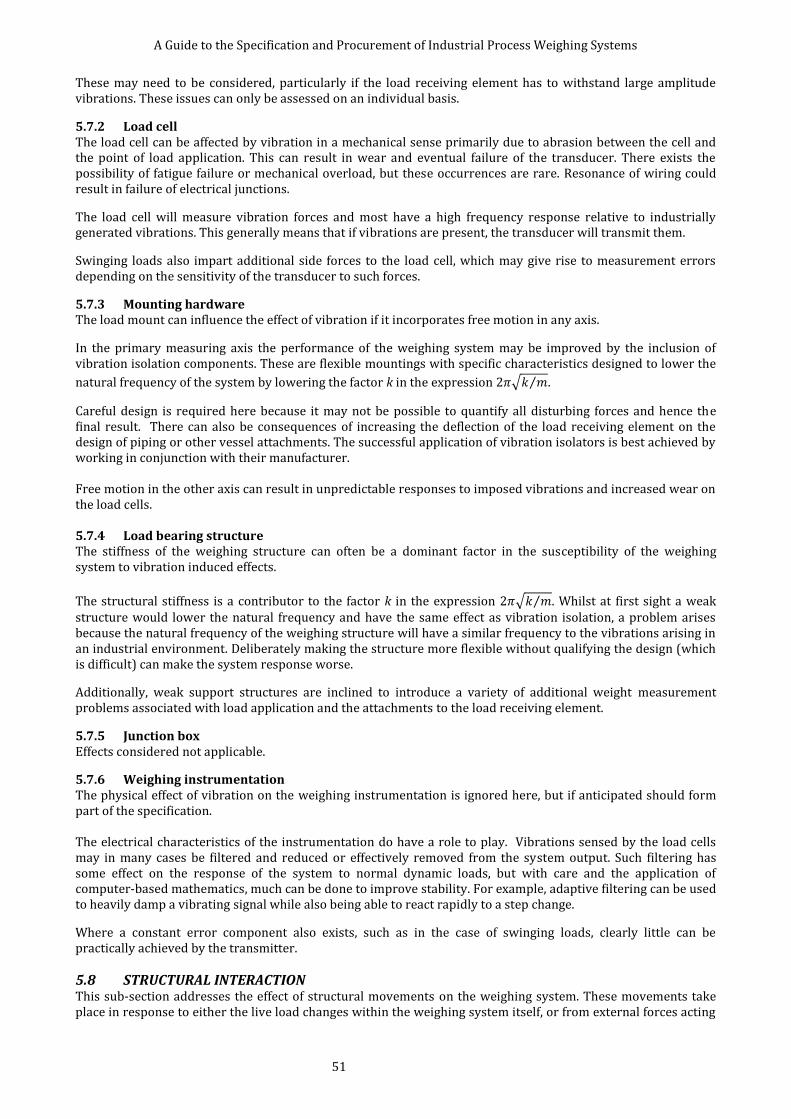
A Guide to the Specification and Procurement of Industrial Process Weighing Systems
51
These may need to be considered, particularly if the load receiving element has to withstand large amplitude vibrations. These issues can only be assessed on an individual basis.
5.7.2 Load cell The load cell can be affected by vibration in a mechanical sense primarily due to abrasion between the cell and the point of load application. This can result in wear and eventual failure of the transducer. There exists the possibility of fatigue failure or mechanical overload, but these occurrences are rare. Resonance of wiring could result in failure of electrical junctions.
The load cell will measure vibration forces and most have a high frequency response relative to industrially generated vibrations. This generally means that if vibrations are present, the transducer will transmit them.
Swinging loads also impart additional side forces to the load cell, which may give rise to measurement errors depending on the sensitivity of the transducer to such forces.
5.7.3 Mounting hardware The load mount can influence the effect of vibration if it incorporates free motion in any axis.
In the primary measuring axis the performance of the weighing system may be improved by the inclusion of vibration isolation components. These are flexible mountings with specific characteristics designed to lower the
natural frequency of the system by lowering the factor k in the expression √ ⁄ .
Careful design is required here because it may not be possible to quantify all disturbing forces and hence the final result. There can also be consequences of increasing the deflection of the load receiving element on the design of piping or other vessel attachments. The successful application of vibration isolators is best achieved by working in conjunction with their manufacturer. Free motion in the other axis can result in unpredictable responses to imposed vibrations and increased wear on the load cells. 5.7.4 Load bearing structure The stiffness of the weighing structure can often be a dominant factor in the susceptibility of the weighing system to vibration induced effects.
The structural stiffness is a contributor to the factor k in the expression √ ⁄ . Whilst at first sight a weak structure would lower the natural frequency and have the same effect as vibration isolation, a problem arises because the natural frequency of the weighing structure will have a similar frequency to the vibrations arising in an industrial environment. Deliberately making the structure more flexible without qualifying the design (which is difficult) can make the system response worse.
Additionally, weak support structures are inclined to introduce a variety of additional weight measurement problems associated with load application and the attachments to the load receiving element.
5.7.5 Junction box Effects considered not applicable.
5.7.6 Weighing instrumentation The physical effect of vibration on the weighing instrumentation is ignored here, but if anticipated should form part of the specification. The electrical characteristics of the instrumentation do have a role to play. Vibrations sensed by the load cells may in many cases be filtered and reduced or effectively removed from the system output. Such filtering has some effect on the response of the system to normal dynamic loads, but with care and the application of computer-based mathematics, much can be done to improve stability. For example, adaptive filtering can be used to heavily damp a vibrating signal while also being able to react rapidly to a step change.
Where a constant error component also exists, such as in the case of swinging loads, clearly little can be practically achieved by the transmitter.
5.8 STRUCTURAL INTERACTION This sub-section addresses the effect of structural movements on the weighing system. These movements take place in response to either the live load changes within the weighing system itself, or from external forces acting

A Guide to the Specification and Procurement of Industrial Process Weighing Systems
52
on the load bearing structure. Many of the effects reviewed here are dealt with in detail elsewhere in this document and are cross-referenced to the appropriate sub-section.
The main interactions relating to the weighing system structure may be listed as: weighing errors due to the applied force being misaligned to the primary axis of the load cell;
weighing errors due to the load cell being subject to side loads or bending moments;
weighing errors due to redistribution of the load between the load cells in a multiple load cell system;
changes in the system response to shock and vibration;
changes in the shunt forces generated by piping, tie bars or other attachments to the load receiving element.
The specification should provide quantitative information relating to the structural strength and loads and consequent movements of the mechanical structures which adjoin the weighing system. Where such data is not available or cannot be quantified, this should be stated. General information on the location and type of structures to be employed may assist the supplier to make an assessment of these structural movements or to lay down general minimum design requirements.
As a general observation, the less structural movement that exists, the better the weighing system performance will be. In higher performance applications, it may be appropriate to give consideration to the provision of totally isolated support structures. Any change in structural support geometry due to e.g. shifting of foundations, loosening of holding-down bolts etc may introduce further errors.
5.8.1 Load receiving element The load receiving element is part of the weighing structure, and the movements of its supports under load should be considered. These movements may result in angular changes to the support surface due to rotation, or positional changes such as might be caused by bellowing out of vessel walls or movement in support legs. It is worthy of note in this context that most load cell designs do not laterally locate these supports and their design may need additional horizontal bracing. Where possible the specification should include drawings of the load receiving element, in particular details of the proposed load cell locations. The specification for the preparation of the load cell support points is usually company specific and depends on their experience with a particular type of load cell used on an installation. It is therefore recommended that advice should be sought from the supplier of the weighing system regarding optimum conditions for the specification of the load support points, sometimes referred to as the cleats or vessel feet.
Connections to the load receiving element such as piping and tie bars are deflected by structural movement. The effects of piping on the structure can be underestimated in that the deflections cause by pipework will have a tendency to impart eccentric loads to the load receiving element. Structural movement of the pipe anchor, which is fixed to the surrounding structure, will also give rise to forces being applied to the weighing system (see also 5.9 Horizontal restraining devices and 5.10 Pipework).

A Guide to the Specification and Procurement of Industrial Process Weighing Systems
53
5.8.2 Load cell The load cell will experience changes during loading due to structural movement. The extent to which the load cells are affected by structural movement is likely to be dependent on the type of mounting hardware that is used in the installation of the load cell. Care should be exercised when an attempt is made to quantify the weigh system errors from the published specifications of load cells. The following points highlight some of the sources of errors which may be present in the installation.
1 The load may not be applied to the load cell directly in line with its principal axis. If it is inclined, the load measured by the load cell will be reduced.
Example: One of the load cells supporting a weigh vessel by means of brackets attached to its wall has an angle of 1° from horizontal. The load seen by the load cell is therefore inclined by 1° from its principal axis. The axial component of this load, seen by the load cell, is reduced by a factor of cos 1.
This represents a reduction of 0.015 % of the applied load. If this angle of inclination does not change during the weigh cycle, the reduction will appear to be a constant and will be compensated by the initial calibration of the weighing system. However, if it changes during the weigh cycle, it will then contribute to the total system error.
2 Any inclined load applied to a load cell is likely to generate a side load. Depending on the sensitivity of the load cell to side loads, this may contribute to the total system error. The angular loading may be concentric inclined loading or eccentric inclined loading. Methods of calculating these forces and establishing their effects are given in reference [11].
Example: One of the load cells supporting a weigh vessel by means of brackets attached to its wall has an angle of 3 from the horizontal, giving rise to an eccentric angular load. The load cell has an eccentric angular load sensitivity established by the manufacturer of 0.05 % of applied load (F). This will result in an output error of 0.05 %× F. If this angle of inclination does not change during the weigh cycle, the error will appear to be a constant and will be compensated by the initial calibration of the weighing system. However, if it changes during the weigh cycle, it will then contribute to the total system error.
3 The load cell may be subjected to side loads resulting from friction between the loading surfaces as the
structure move relative to each other. The load cell or the mounting hardware must be capable of withstanding these side loads, which may be significant.
Example: One of the load cells supporting a weigh vessel has a static coefficient of friction of 0.3 between its loading surface and the surface of the support lug. The support beam is subject to a lateral deflection under load. The load cell has a sensitivity to side loads established by its manufacturer of 0.25 % of side load applied via its mounting hardware. The load cell is subject to a side load of 0.3 × F, where F is the applied load. This side load will result in a load cell output of (0.25/100) × 0.3 × F = (0.075/100) × F or 0.075 % × F.
4 The distribution of load in a multiple load cell system may change due to differential deflections of the structure, which may in turn give rise to measurement errors (see 4.3 Multiple load cell applications).
5.8.3 Mounting hardware The mounting hardware may be required to be specified to accommodate or reduce the effects of structural interaction. Mounting assemblies may be specified to permit the relative motion or poor alignment of the load receiving element and the load bearing structure. The careful choice and use of suitable mounting hardware can reduce some of the errors caused by structural movement.

A Guide to the Specification and Procurement of Industrial Process Weighing Systems
54
The mounting hardware must be able to withstand the horizontal loads that may be experienced due to structural movement. The location of mounting hardware to the load bearing structure should also be considered in this context. In particular, where the load bearing structure is non-metallic, the specification of holding down bolts, and their locations may need to be included as part of the specification. The use of epoxy resins or grouts may be suitable in some installations. 5.8.4 Load bearing structure The load bearing structure itself may be specified in terms of minimising its effect on the weighing system. In considering the design of the load bearing structure, the overall strength of the structure may be specified with reference to the maximum permissible deflection ratios when subjected to the live load. The location of load cells in relation to the support structure geometry will be an issue if excessive twisting of supports is to be avoided. This is particularly relevant to beam load cells in which the load will not usually be applied symmetrically to the mounting assembly. There are guidelines relating the deflection of the load bearing structure to the performance of the weighing system, used as a basis for specifying structural work. These guidelines are empirical and based on the experience of the specifier, contractor or manufacturer of the weighing systems. In general, a stiffer structure (i.e. lower deflection) will result in a better performing weighing system, but the load cell type may also have an influence on this performance. Consideration should also be given to the immunity of the structure from deflections caused by variable loads such as might be present when adjacent vessels are loaded or the support floor is loaded by moving plant or machinery. It may be necessary to isolate the weighing system from the effects of vibration and shock by means of anti-vibration mounts or physical separation of the system from the surrounding structures (see 5.6 Impact and 5.7 Vibration). There is an additional benefit in minimising the load bearing structure deflections, since this will also reduce the interaction of the force shunts such as the pipework and the horizontal restraining devices. Constructional issues such as the tolerances applied to the levelling, flatness and finish of loading bearing surfaces where the load cells are installed may also need to be included in the specification. The provision of shims may be a requirement for multiple load cell installations.
5.8.5 Junction box Effects considered not applicable.
5.8.6 Weighing instrumentation Effects considered not applicable.

A Guide to the Specification and Procurement of Industrial Process Weighing Systems
55
5.9 HORIZONTAL RESTRAINING DEVICES In some weighing applications, the load cells or the load receiving element may need to be protected from excessive horizontal forces. A range of restraining devices may be installed horizontally between the load receiving element and the load bearing structure in order to achieve this protection.
The reasons for using horizontal restraining devices are: to achieve stability in tall vessels in the presence of horizontal loads caused by vibration, seismic loads or
wind; to protect the load cells from horizontal loads, which may be generated by external influences such as
thermal expansion, forklift truck collision or when an agitator or vibrator is used; to restrain the load receiving element, installed on mounting hardware utilising free motion units where the
vessel has freedom of movement in a horizontal direction. The main effects of horizontal restraints may be listed as: errors in the load measurement caused by vertical spring forces generated in the restraints when the load
receiving element is deflected by the live load; they influence the load distribution on the load cells unless they are identical and positioned with care; they can generate horizontal loads due to thermal stresses where there are differential expansions; they require to be installed horizontally and with a predetermined built-in stress, i.e. the nuts at the clamped
points tightened with a specific torque; incorrectly positioned tie bars may cause unpredictable non-linearity, hysteresis and repeatability errors. These restraining devices may be in the form of: 1. Tie bars may have round, hexagonal or other profiles but are usually in the form of solid round rods since
these are easy to apply and install. They are referred to by several names in commercial literature some of which are listed below: Struts Stay rods Lateral supporting struts Tie rods Guide elements
There are several commonly used configurations for tie bars. Their contribution as force shunts should be calculated and some are listed below in descending order of force shunting effect: clamped rigidly at both ends; clamped at both ends with the use of spherical washers; mounted with spherical bearings at one or both ends; mounted with pivots at one or both ends, usually utilising ball bearings. 2. Flexures, usually straps or bands. These are commonly used in ‘Loading Units’, which are designed as
protection for canister-type load cells. These are used when the force shunt value has to be limited. 3. Tension wires, taut wires installed between the load receiving element and the load bearing structure. These
are used generally in applications where the shunt force has to be limited to a very small value. They only afford protection in tension and the vessel requires additional protection if there are compressive forces present in the application. They may be designed to have very low force shunt values and their contribution is usually negligible.

A Guide to the Specification and Procurement of Industrial Process Weighing Systems
56
For a solid rod of circular cross-section, rigidly anchored at each end, the shunt force may be computed from the equations:
where: F is the shunt force generated by the tie bar, E is the Young’s modulus, 210 kN·mm-2 for carbon steel, I is the second moment of area or moment of inertia of the bar cross-section, L is the length of the tie bar, D is the diameter of the tie bar, y is the deflection of the tie bar.
(a)
(b)
Figure 5.9.1 Examples of tie bar configurations: (a) a circular load receiving element is on free motion
arrangement; (b) conventional arrangement using clevis forks and rod ends. 5.9.1 Load receiving element Restraining devices act as force shunts in a similar manner to pipe connections, and their effect on the performance of the weighing system should be accounted for when calculating the total shunt forces in accordance with the equation for Ft/g (given in 5.10 Pipework).
Example 1: A load receiving element is restrained with the use of four carbon steel tie bars of 20 mm diameter and 500 mm length. The estimated deflection of the vessel between the tie bar clamping points is 0.5 mm at full working load.
The force shunt by a single tie bar can be calculated from the following equations:
where: E = 210 000 N·mm-2 D = 20 mm, L = 500 mm, y = 0.5 mm.
Substituting, ⁄ and ⁄ { } The total shunt force for all four tie bars is 317 N {32 kg}. This needs to be considered, together with any piping shunt forces, against the performance requirements as explained in 5.10 Pipework.
A Guide to the Specification and Procurement of Industrial Process Weighing Systems
57
Example 2: In Example 1 above, the tie rod has been subjected to a temperature rise of 30 C. The horizontal force generated, for a rigidly held tie bar with negligible built-in stress, as the result of this temperature change can be computed from the equation given in section 5.1.1:
where: A = 314 mm2 E = 210 000 N·mm-2 = 12 × 10–6 m·m-1·°C-1 T = 30 C
Substituting, we have: { }
The above load is applied horizontally to the brackets at each end of the tie bar.
5.9.2 Load cell The effects of the shunt forces on the load cell are essentially the same as for the load receiving element. In some applications the load cells, such as the shear beam type, may act as tie bars in the horizontal direction. In these cases the application may not require additional protection from horizontal loads. It is advisable to estimate the side loads that may be present in the application and compare this to the safe side load capability of the load cells to be installed. 5.9.3 Mounting hardware Some load cells are supplied with associated mounting hardware with built-in side load protection devices. It is advisable to estimate the side loads that may be present in the application and compare this to the safe side load capability of the load mounting hardware. 5.9.4 Load bearing structure The horizontal restraints should be securely attached to the load bearing structure at a location which minimises the live load deflection of the restraint. 5.9.5 Junction box Effects considered not applicable.
5.9.6 Weighing instrumentation Effects considered not applicable.

A Guide to the Specification and Procurement of Industrial Process Weighing Systems
58
5.10 PIPEWORK This subsection discusses the effects of piping connected to the load receiving element. Piping attachments add both to the dead weight, and impose additional forces which may be measured by the load cells. These factors along with process considerations will inform the final piping design. The main effects of pipe connections may be listed as: errors in the load measurement caused by vertical spring forces generated in the pipe connections when the
load receiving element is deflected by the live load;
errors in the load measurement caused by restriction of the thermal expansion of the load receiving element by pipework;
errors in the load measurement due to thermal expansion of the pipework;
errors in the load measurement caused by pressure changes within flexible pipe couplings. Some of the above factors may only cause a zero shift whilst others will additionally cause a change in span. For some applications, particularly when weighing measurements are made by difference such as when using automatic taring, changes in zero load output may not be important. The specification should state the process conditions - both temperature and pressure under which measurements will be made. The supplier and/or user should perform a detailed analysis of the piping system to assess the magnitude of these effects and this analysis should become part of the specification. Where such an analysis is impracticable or limited in scope - this should be stated. After installation, and with zero live load, the forces generated by piping connections are limited to a proportion of their additional weight, and any forces introduced during construction and support. When the load receiving element is deflected by a live load, the piping is strained and a spring force is generated. If this deflection is repeatable and directly related to the increase in load, such as might be due to the load cell deflection, then the forces may be compensated during the calibration of the weighing system. However, there may be deflections around the structure, caused by factors, which are not necessarily repeatable. Consideration should be given to these deflections, where they affect the pipe connections. Some of the important contributory factors are: deflection of the load cell;
deflection of the mounting hardware, particularly if shock or vibration isolation is employed (see 5.6 Impact and 5.7 Vibration);
deflection of the load bearing structure;
deflection of the load receiving element structure. The forces generated by these combined deflections may have significant effects on the weighing system output, influencing its linearity, hysteresis, and repeatability. It is therefore advisable to reduce the forces, if process requirements permit, by the following methods: reducing the total number of connections;
reducing the total deflections where possible, by using rigid structures;
applying mechanical design criteria to reduce the stiffness of the piping. This is generally achieved by using smaller diameter pipes, thinner wall thickness material, and appropriate connection configurations with long horizontal runs or incorporating elbows or other changes in direction. The wall thickness of pipes is identified by a schedule number [13, 18];
utilising flexible couplings in the connections to the load receiving element - these assemblies will generally have lower spring rates than normal pipe runs, but they may still be significant.
Changes of process temperature or selective ambient temperature changes can produce deflections at the pipe connections. These deflections can be in any direction. Deflections in the vertical axis will give rise to changes in the zero load output of the weighing system. Deflections in the horizontal plane will generate thermal stresses (see 5.1 Temperature). They may also give rise to weighing errors due to changes in load distribution between load cells; this is of particular relevance where dummy load cells are employed as pivots.
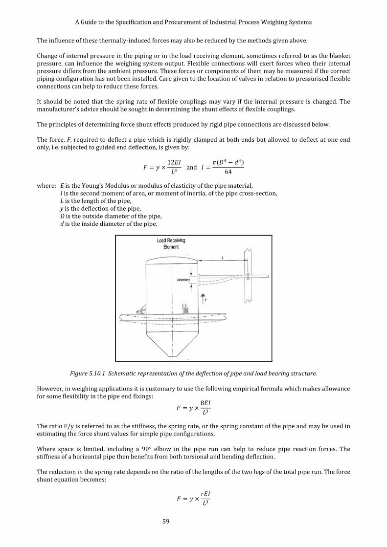
A Guide to the Specification and Procurement of Industrial Process Weighing Systems
59
The influence of these thermally-induced forces may also be reduced by the methods given above. Change of internal pressure in the piping or in the load receiving element, sometimes referred to as the blanket pressure, can influence the weighing system output. Flexible connections will exert forces when their internal pressure differs from the ambient pressure. These forces or components of them may be measured if the correct piping configuration has not been installed. Care given to the location of valves in relation to pressurised flexible connections can help to reduce these forces. It should be noted that the spring rate of flexible couplings may vary if the internal pressure is changed. The manufacturer’s advice should be sought in determining the shunt effects of flexible couplings. The principles of determining force shunt effects produced by rigid pipe connections are discussed below. The force, F, required to deflect a pipe which is rigidly clamped at both ends but allowed to deflect at one end only, i.e. subjected to guided end deflection, is given by:
( )
where: E is the Young’s Modulus or modulus of elasticity of the pipe material,
I is the second moment of area, or moment of inertia, of the pipe cross-section, L is the length of the pipe, y is the deflection of the pipe, D is the outside diameter of the pipe, d is the inside diameter of the pipe.
Figure 5.10.1 Schematic representation of the deflection of pipe and load bearing structure. However, in weighing applications it is customary to use the following empirical formula which makes allowance for some flexibility in the pipe end fixings:
The ratio F/y is referred to as the stiffness, the spring rate, or the spring constant of the pipe and may be used in estimating the force shunt values for simple pipe configurations. Where space is limited, including a 90° elbow in the pipe run can help to reduce pipe reaction forces. The stiffness of a horizontal pipe then benefits from both torsional and bending deflection. The reduction in the spring rate depends on the ratio of the lengths of the two legs of the total pipe run. The force shunt equation becomes:

A Guide to the Specification and Procurement of Industrial Process Weighing Systems
60
where r is known as the clamping factor. Indicative estimates of r are given in table 5.10.1.
Figure 5.10.2 Schematic representation of pipe connections in vertical and horizontal planes.
A/L B/L r
0.0 - 12.0
0.2 - 7.9
0.5 - 7.1
1.0 - 6.3
5.0 - 4.4
- 0.0 12.0
- 0.2 6.8
- 0.5 4.6
- 1.0 2.3
- 5.0 0.06
Table 5.10.1 Clamping factors for pipe connections in vertical and horizontal planes. A, B, and L are defined in figure 5.10.2 and r is the value of the clamping factor computed using a pipe stress analysis program [14]. The pipe used in the analysis was a schedule 40, 1.5 inch nominal diameter pipe with fixed ends and long radius bends. These values of r could also be de-rated by 0.66 to allow for some fixed end rotation. It should be noted that the configuration including a vertical leg imposes additional side loads onto the load receiving element. This force may be important in some applications, particularly those partly supported systems incorporating pivots.
Example: The vessel considered above, with a single 1.5” diameter carbon steel schedule 40 pipe, having 1 m horizontal length with a 1 m vertical leg, is subjected to a vertical force, i.e. a force shunt of 84 N {8.6 kg} for every 1 mm of vertical deflection of the vessel at the point of connection.
More complex pipe configurations can be analysed manually, but are more usually subject to computer analysis. However, the simple formulae given above are often adequate to provide an estimate of pipe forces.

A Guide to the Specification and Procurement of Industrial Process Weighing Systems
61
5.10.1 Load receiving element Good design practice should be employed to minimise the shunt forces produced by pipework connected to the load receiving element, and to ensure that the maximum loading on vessel connection points are not exceeded. The maximum total force (i.e. the arithmetical sum of all the pipe connection shunt forces) should not exceed Ft, where Ft can be calculated from the following empirical formula:
( )
Example A: For a weighing system designed to weigh a live load of 10 000 kg with a maximum permissible error of ±0.05 % RL, the maximum permissible pipe shunt force can be calculated as:
(
)
When hot or cold material is fed through a pipe the thermal expansion or contraction of the pipe will introduce a force on the load receiving element. Similarly, changes in the temperature of the load receiving element or load bearing structure will result in dimensional changes that may in turn result in forced deflections of the pipework. The magnitude of these forces can be difficult to calculate but some estimate can be made using the stiffness of the pipe connections. Again, computer analysis can yield more detailed estimates of these effects.
Example B: Consider a 5 000 kg capacity vessel with a required accuracy of 0.05 %. It has two horizontal pipe connections to it. One is a 2 m long schedule 40 size 1.5 carbon steel pipe on the outlet; and the other is a 0.2 m long 50 mm diameter pipe installed with a stainless steel flexible coupling having a spring rate of 10 N·mm-1. The load cells deflect 0.2 mm at the maximum working load. At the point of pipe connection the deflection due to flexing of the load bearing structure is 1.5 mm, and the deflection caused by distortion of the load receiving element is 0.6 mm. Then, for the required performance, the total shunt force:
(
)
The force shunt by the outlet pipe can be calculated from the following equations,
( )
where E = 210 000 N·mm-2 D = 48.26 mm (1.900) d = 40.89 mm (1.610) L = 2 000 mm. D and d are found from piping tables for schedule 40 pipes.
A Guide to the Specification and Procurement of Industrial Process Weighing Systems
62
Total deflection at the pipe attachment point:
y= 0.2 + 1.5 + 0.6 = 2.3 mm Second moment of area for the outlet pipe is:
I= 129 042 mm4 and force shunt exerted by the outlet pipe is:
Ft = 62.3 N {6.35 kg}
The total pipe shunt force including the shunt force exerted by the flexible coupling is:
62.3 + (2.3 x 10) = 85.3 N {8.7 kg} This is below the target of 25 kg, therefore the vessel should achieve the required weighing accuracy based on these considerations alone.
5.10.2 Load Cell The effects of pipework on the load cell are essentially the same as the effect on the load receiving element, but the influence on the weighing system output will depend on the design of the load cell and, to some extent, on the mounting hardware. The deflection of a load cell at rated load depends on the design and can typically vary from 0.1 mm to 10 mm. The in-service deflection will also depend on the load cell utilisation in the particular application. The pipe connections may give rise to side loads being applied to the load cell. This may be a consideration when selecting a type or range of transducer for a particular application. 5.10.3 Mounting hardware The pipework is not likely to directly influence the mounting hardware, except in that the mounting hardware must be capable of retaining the vessel under the influence of any side forces introduced by the pipework while still allowing free movement in the vertical plane. 5.10.4 Load bearing structure The pipe fixed end or anchor is likely to be located somewhere on the load bearing structure. Giving careful consideration to the deflection and security of these anchors (see 5.8 Structural interaction), can reduce the magnitude and repeatability of the pipe spring load. 5.10.5 Junction box Effects considered not applicable. 5.10.6 Weighing instrumentation Effects considered not applicable.

A Guide to the Specification and Procurement of Industrial Process Weighing Systems
63
6 SPECIAL CONSIDERATIONS 6.1 HAZARDOUS AREA WEIGHING SYSTEMS Weighing systems used in an area where an unavoidable, potentially explosive atmosphere may exist must comply with the appropriate relevant safety regulations. The purpose of this sub-section is to consider the effect that the safety systems have on weighing system performance, and not to inform the design of suitable safety systems. For a flammable incident to occur there must be a source of combustible gas, vapour, or dust, an oxygen supply, and sufficient energy to cause ignition. Within the context of this document, the ignition source is either in the form of heat or electrical energy. The protection of the weighing system involves some or all of the following: preventing the flammable material from coming into contact with the source of ignition; containing any incident to prevent damage to people or property; limiting the energy to levels below which ignition can occur. The main effects of these protection measures on the performance of the weighing system may be listed as: errors in the load cell output due to mechanical interference from the protective measures; lowering of the available measuring output from the load cells by the use of energy limiting components,
with consequent penalties on performance; thermally related errors due to the temperature coefficients of energy limiting components; operational or serviceability limitations of instrumentation due to protective enclosures. The regulations governing the use of electrical equipment in potentially flammable hazard areas vary around the world, often being influenced by prior industry practice. These regulations are subject to constant review and change. It is therefore critical for the user to be satisfied that the specification contains the correct and current regulatory requirements; and that the supplier is satisfied that the equipment provided meets those regulations. Whilst it is possible for a user or supplier to present a technically competent case for the safe use of equipment in certain circumstances, it is almost universal practice to utilise third party certification authorities to validate the safety of any equipment used. In 2003, the European Directive 94/9/EC, known as the ATEX Directive, came into force. The directive relates to a broad range of equipment and protective systems intended for use in potentially explosive areas. This document provides an outline of the relevant regulations insofar as they are known at the time of publication. A list of publications appears in the bibliography. Much of the general content is very similar to that of the European CENELEC standards already in existence. The ATEX Article 137 was not transposed directly but was implemented by DSEAR (The Dangerous Substances and Explosive Atmospheres Regulations 2002). It is a Statutory Instrument (SI 2002 No 2776) introduced into UK Legislation on 9 December 2002. There was a transitional period for full compliance which ended on 30 June 2006. The duties in DSEAR apply alongside the HSW Act. Scope of the DSEAR Regulations: • Wherever there is work carried out by employer or self-employed persons • Wherever a dangerous substance is present or is liable to be present • Wherever the dangerous substance poses a risk to the safety (not health) of the person The ATEX directive makes a distinction between equipment used in Mining and Non-mining applications:
For non-mining applications a further classification is made relating to the type of explosive atmosphere likely to be present:
Group I Mining Group II Non-mining

A Guide to the Specification and Procurement of Industrial Process Weighing Systems
64
For gas/air mixtures and dusts, typical substances are used to illustrate the ease of ignition by electrical spark. These groups are:
The final classification of gases concerns their ease of ignition from exposure to a hot surface:
Where equipment carries a temperature class, it is usually qualified with reference to an ambient temperature range, usually -20 °C to +40 °C. There are various degrees of protection which are listed as: Mining Equipment - Group I Category M1 - A very high level of protection. Equipment can be operated in the presence of the explosive atmosphere. Category M2 - A high level of protection. Equipment must be de-energised in the presence of the explosive atmosphere. Non-mining Equipment - Group II Category 1 - A very high level of protection. Used where the hazard is present continuously or for a long period of time. (Gas = Zone 0; dust = Zone 20). Category 2 - A high level of protection. Used where the hazard is likely to occur in normal operation. (Gas = Zone 1; dust = Zone 21). Category 3 - A normal level of protection. Used where the hazard is unlikely to occur, but if it does would only be present for a short period of time. (Gas = Zone 2; dust = Zone 22). Manufacturers of certified equipment have to submit their designs to a competent authority for assessment and to then have in place quality control procedures, which ensure the approved designs are implemented in the final product. Certified equipment must carry indelible markings, which identify its conformity to the various classifications mentioned above in a format laid down in the regulations.
Group G Gas/Vapour/Mist Group D Dust
I Methane (Mining only) IIA Propane IIB Ethylene IIC Hydrogen IIIA Combustible flyings IIIB Non-conductive dust IIIC Electrically conductive dusts
Max. Surface T Class Temperature T1 450°C T2 300°C T3 200°C T4 135°C T5 100°C T6 85°C

A Guide to the Specification and Procurement of Industrial Process Weighing Systems
65
6.1.1 Load receiving element There may be some relevant regulations relating to generation of ignition energy by the materials of construction, usage and earthing of the load receiving element, but these are not usually the direct concern of the weighing system supplier. Where an issue is deemed to be relevant, it must form part of the specification. 6.1.2 Load cell There are various protection methods applicable to load cells, but some common techniques in use are: Intrinsic Safety (coded i); Non-Incendive (coded n); and Pressurised (coded p) – see 6.1.6 Weighing Instrumentation for further information.
The technique of Intrinsic Safety relies on the use of appropriate electronic components acting as a barrier between the safe and the hazardous area equipment.
Commonly-used barrier components are Zener diode shunt protection barriers, which limit the electrical energy available to the load cells.
These devices affect the weighing system in three ways:
1. They have internal resistance, which lowers the available excitation voltage applied to the load cells. This consequently lowers the available signal-to-noise ratio and decreases the system performance. For many weighing systems this degradation in performance is small and intrinsically safe systems are available which maintain Class III performance in accordance with BS EN 45501.
2. The Zener diodes can generate thermal voltages when subject to temperature gradients, which are then apparent as errors in the weighing system output. Consideration should be given to the location of barrier components, or to eliminating these effects with special circuitry within the weighing instrumentation.
3. The operation of Zener barriers is dependent upon a secure correctly implemented earthing system. This may have consequences for the earthing regimes used in connection with the signal screening circuits within the load cell.
Example: To illustrate the effect of Zener barriers on energisation voltage Three load cells, each with a nominal bridge input resistance of 350 , are energised by a 10 V dc power supply. To achieve a safe circuit, Zener barriers are inserted generally in accordance with the circuit diagram in this sub-section. The manufacturer states that the maximum end-to-end resistance of each of the two channel supply barriers is 93 .
Figure 6.1.1 Typical connection diagram for safety barriers used in load cell
A Guide to the Specification and Procurement of Industrial Process Weighing Systems
66
The resistance of the parallel combination of the three load cells is 350/3 = 117 . The energisation voltage can be calculated from the resultant potential divider as:
The maximum potential measuring signal is thus reduced by 61 %.
Barriers using galvanic isolators may also be utilised. These devices depend on the use of transformers and opto-electronic components to provide isolation, they are active devices and have transfer errors in their own right but do offer the distinct advantage that secure earthing regime is not a requirement. These devices affect the weighing system in three ways: 1. They lower the available excitation voltage applied to the load cells. This consequently lowers the available
signal-to-noise ratio and decreases the system performance. 2. They have active components within them, which incur non-linearity error as well as imparting additional
noise to the weighing signals. 3. They have a defined and substantial temperature coefficient. Typically such components have an output
which can vary by 0.1 % per 5 °C or worse. Weighing instrumentation with galvanic isolation built-in is available, and in these cases compensation for non-linearity and thermal effects becomes part of the design. The technique of intrinsic safety Code i(a) is acceptable for Categories M1 and 1 (Zones 0 & 20); whilst Code i(b) is only acceptable in Categories M2 and 2 (Zones 1 & 21). Whilst there are standards relating to the use of uncertified load cells by allowing the manufacturer to declare them to be “Simple Apparatus” [4], most users and suppliers prefer to specify the use of formal third party certification. Most approval authorities around the world do not view load cells as ‘simple apparatus’, as examination of designs has shown that most cells have components which, unprotected, could cause an ignition hazard. The specification should state what formal certification exists for the load cell and any associated barriers used. Where no current relevant certificates exist, this should also be stated. Non-Incendive protection (Code n) relies on the sealing and mechanical construction of the load cell to preclude the occurrence of an ignition hazard. This form of approval is only acceptable in Category 3 (Temperature Class T4) areas (Zones 2 & 22) and has not been universally adopted. However, the method has the advantage that no safety barriers are required. For some approvals it is necessary for the manufacturer to surround the strain gauges with a filler material, this may have an adverse effect on the performance of the load cell. Where this is the case, it should be stated on the specification. 6.1.3 Mounting hardware With the exception of possible system earthing requirements, there are no effects on mounting hardware. 6.1.4 Load bearing structure Effects considered not applicable.
6.1.5 Junction box and cable The junction box should comply with any relevant regulations for the area in which it is installed, and be wired in accordance with the systems certificate relating to the load cells. The manufacturer’s advice should be sought for approved wiring diagrams and in particular the requirements for any load cell extension cable used. The extension cable is an energy storing component and will form part of any system certification.
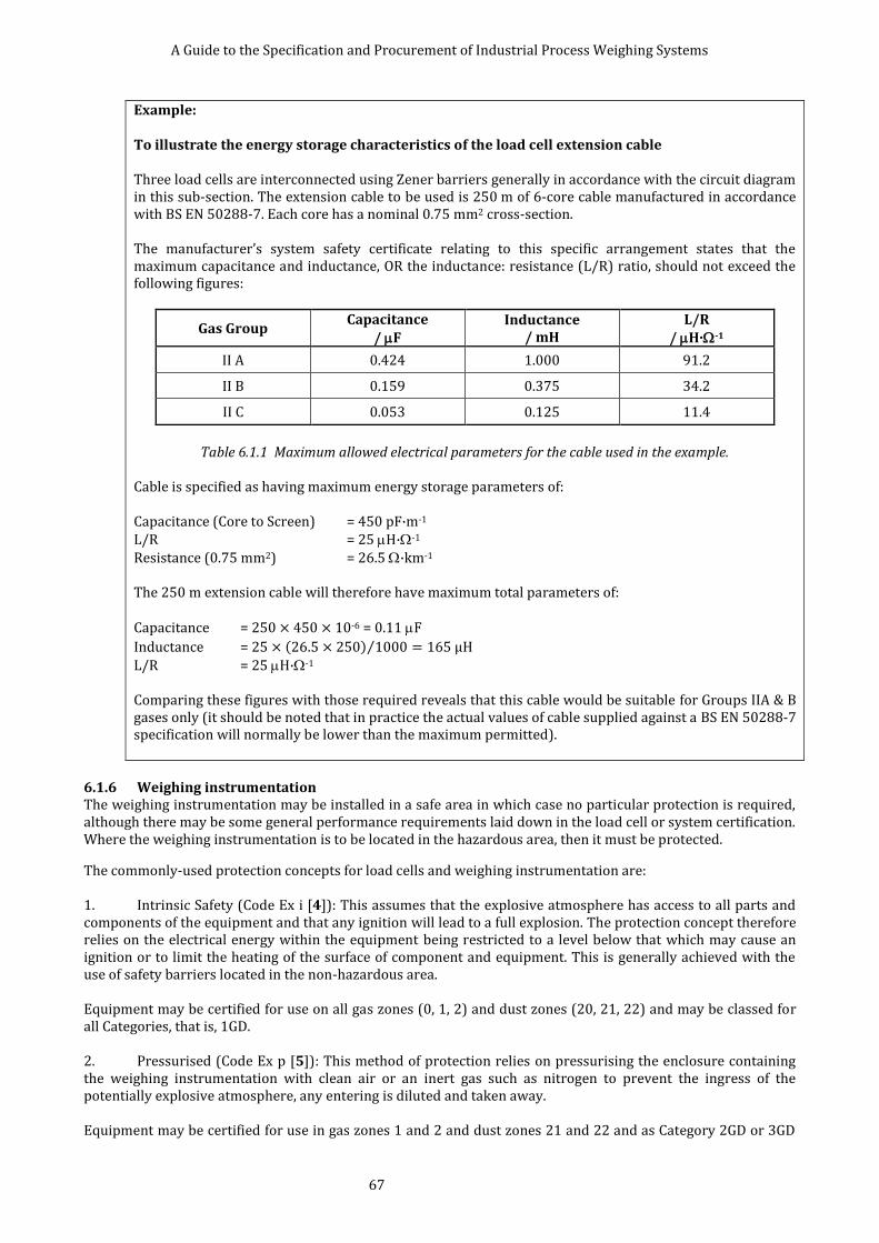
A Guide to the Specification and Procurement of Industrial Process Weighing Systems
67
Example: To illustrate the energy storage characteristics of the load cell extension cable Three load cells are interconnected using Zener barriers generally in accordance with the circuit diagram in this sub-section. The extension cable to be used is 250 m of 6-core cable manufactured in accordance with BS EN 50288-7. Each core has a nominal 0.75 mm2 cross-section. The manufacturer’s system safety certificate relating to this specific arrangement states that the maximum capacitance and inductance, OR the inductance: resistance (L/R) ratio, should not exceed the following figures:
Gas Group Capacitance
/ F Inductance
/ mH L/R
/ H·-1
II A 0.424 1.000 91.2
II B 0.159 0.375 34.2
II C 0.053 0.125 11.4
Table 6.1.1 Maximum allowed electrical parameters for the cable used in the example.
Cable is specified as having maximum energy storage parameters of: Capacitance (Core to Screen) = 450 pF·m-1 L/R = 25 H·-1 Resistance (0.75 mm2) = 26.5 ·km-1 The 250 m extension cable will therefore have maximum total parameters of: Capacitance = 250 450 10-6 = 0.11 F
Inductance = ( ) ⁄
L/R = 25 H·-1 Comparing these figures with those required reveals that this cable would be suitable for Groups IIA & B gases only (it should be noted that in practice the actual values of cable supplied against a BS EN 50288-7 specification will normally be lower than the maximum permitted).
6.1.6 Weighing instrumentation The weighing instrumentation may be installed in a safe area in which case no particular protection is required, although there may be some general performance requirements laid down in the load cell or system certification. Where the weighing instrumentation is to be located in the hazardous area, then it must be protected.
The commonly-used protection concepts for load cells and weighing instrumentation are: 1. Intrinsic Safety (Code Ex i [4]): This assumes that the explosive atmosphere has access to all parts and components of the equipment and that any ignition will lead to a full explosion. The protection concept therefore relies on the electrical energy within the equipment being restricted to a level below that which may cause an ignition or to limit the heating of the surface of component and equipment. This is generally achieved with the use of safety barriers located in the non-hazardous area. Equipment may be certified for use on all gas zones (0, 1, 2) and dust zones (20, 21, 22) and may be classed for all Categories, that is, 1GD. 2. Pressurised (Code Ex p [5]): This method of protection relies on pressurising the enclosure containing the weighing instrumentation with clean air or an inert gas such as nitrogen to prevent the ingress of the potentially explosive atmosphere, any entering is diluted and taken away. Equipment may be certified for use in gas zones 1 and 2 and dust zones 21 and 22 and as Category 2GD or 3GD
A Guide to the Specification and Procurement of Industrial Process Weighing Systems
68
equipment. 3. Encapsulation (Code Ex m): This method of protection is based on encapsulating the incendive components intended for use in explosive gas or explosive dust atmospheres. Equipment may be certified for use in all gas (0, 1, 2) and dust zones (20, 21, 22) and may be all categories, that is, 1GD. (Reference IEC 60079-18). 4. Protection by enclosure (Code Ex t): This method of protection relies on tight and rugged enclosure design where the explosive atmosphere does not reach the incendive components. This protection concept is only applicable to explosive dust environment and the equipment may be certified for use in all dust zones (20, 21, and 22) and may be classed as Category 1D. (Reference IEC 60079-31). 5. Non-Incendive (Code Ex n [6]): This method of protection is only acceptable for gas zone 2 and classified as Category 3G equipment. There are four methods of protection within this concept. These are; Ex nA components used are non-sparking, Ex nR components are tightly enclosed to restrict the breathing and thus prevent ignition, Ex nC components used are non-incendive, Ex nL components used do not contain enough energy to cause ignition. The supplier should state in the specification which protection method and certification are being offered.
6.2 ELECTRICAL STORMS AND EARTHING This sub-section reviews the effects of electrical storms and other high levels of electrical activity in the vicinity of the weighing system. The effects of interference from electromagnetic fields from more conventional sources such as radios are also considered.
In a strain gauge load cell the gauges are necessarily bonded in intimate contact with the metallic loading element. The insulation between the gauges and the body of the cell may be able to withstand a potential difference of a few hundred volts. The gauges are then connected via cables to electronic instrumentation. The input circuits may or may not be isolated from earth, and in any event the degree of isolation is unlikely to be able to withstand potential differences higher than about 1 000 V. Therefore it is clear that the potential differences associated with electrical storms, which in lightning discharges are in the range of 10 MV to 100 MV, can cause catastrophic damage to the weighing system.
The main effects of lightning on the weighing system may be listed as:
1. A direct strike from cloud to ground lightning (direct attachment). This can be the most devastating, due to the enormous energy that is dissipated. These direct strikes are associated with physical shock damage as well as associated thermal damage. Many weighing systems act as ideal targets for such strikes, especially in open or elevated sites.
2. Capacitive and inductive coupling from cloud to cloud or from cloud to ground lightning. This occurs due to the rapidly changing electromagnetic fields associated with lightning, which can result in voltage spikes being produced in equipment cables by capacitive coupling. Simultaneously, huge current flow can induce transient currents into cables through mutual inductance.
3. Ground potential surges caused by a cloud to ground strike, often known as resistive coupling. The ground has a finite resistance and therefore adjacent buildings and structures can be at different ground potentials. Any cables linking these locations will also experience the potential difference. This effect often causes the most problems, as the frequency of occurrence is much higher than direct strikes.
Careful consideration should be given to this natural phenomenon during the specification stage of a project, particularly where the load receiving element is to be located outdoors in areas of high storm activity. Although it is difficult to design for complete protection, good design practice and maintenance combined with proprietary lightning surge protection equipment can minimise the risk of irreparable damage. Where lightning is foreseen as a problem, the provision of protection equipment should become part of the specification. Where additional surge protection components are to be fitted, other than as part of the original equipment supply, the original supplier should be informed and consulted as such items may adversely affect the weighing system performance.
Other sources of high electrical energy should also be considered the most common being the high currents and consequent induced voltage spikes resulting from electric welding. The load cells should not be installed in
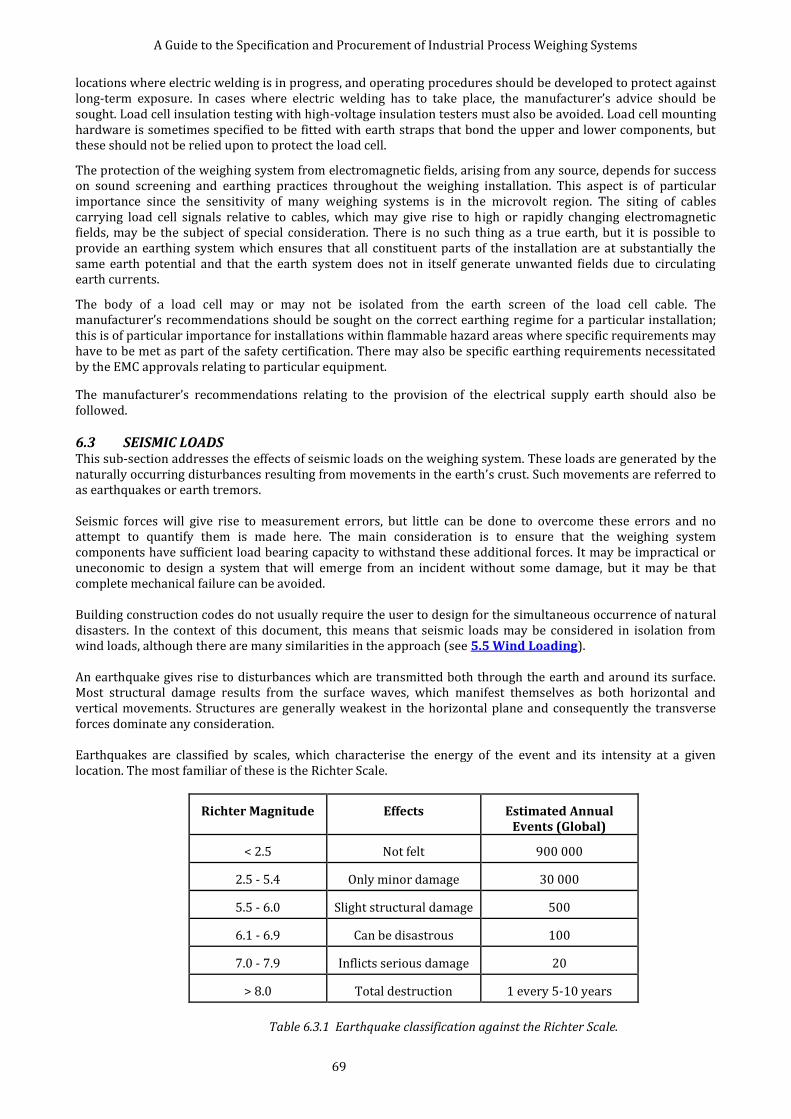
A Guide to the Specification and Procurement of Industrial Process Weighing Systems
69
locations where electric welding is in progress, and operating procedures should be developed to protect against long-term exposure. In cases where electric welding has to take place, the manufacturer’s advice should be sought. Load cell insulation testing with high-voltage insulation testers must also be avoided. Load cell mounting hardware is sometimes specified to be fitted with earth straps that bond the upper and lower components, but these should not be relied upon to protect the load cell.
The protection of the weighing system from electromagnetic fields, arising from any source, depends for success on sound screening and earthing practices throughout the weighing installation. This aspect is of particular importance since the sensitivity of many weighing systems is in the microvolt region. The siting of cables carrying load cell signals relative to cables, which may give rise to high or rapidly changing electromagnetic fields, may be the subject of special consideration. There is no such thing as a true earth, but it is possible to provide an earthing system which ensures that all constituent parts of the installation are at substantially the same earth potential and that the earth system does not in itself generate unwanted fields due to circulating earth currents.
The body of a load cell may or may not be isolated from the earth screen of the load cell cable. The manufacturer’s recommendations should be sought on the correct earthing regime for a particular installation; this is of particular importance for installations within flammable hazard areas where specific requirements may have to be met as part of the safety certification. There may also be specific earthing requirements necessitated by the EMC approvals relating to particular equipment.
The manufacturer’s recommendations relating to the provision of the electrical supply earth should also be followed.
6.3 SEISMIC LOADS This sub-section addresses the effects of seismic loads on the weighing system. These loads are generated by the naturally occurring disturbances resulting from movements in the earth’s crust. Such movements are referred to as earthquakes or earth tremors. Seismic forces will give rise to measurement errors, but little can be done to overcome these errors and no attempt to quantify them is made here. The main consideration is to ensure that the weighing system components have sufficient load bearing capacity to withstand these additional forces. It may be impractical or uneconomic to design a system that will emerge from an incident without some damage, but it may be that complete mechanical failure can be avoided. Building construction codes do not usually require the user to design for the simultaneous occurrence of natural disasters. In the context of this document, this means that seismic loads may be considered in isolation from wind loads, although there are many similarities in the approach (see 5.5 Wind Loading). An earthquake gives rise to disturbances which are transmitted both through the earth and around its surface. Most structural damage results from the surface waves, which manifest themselves as both horizontal and vertical movements. Structures are generally weakest in the horizontal plane and consequently the transverse forces dominate any consideration. Earthquakes are classified by scales, which characterise the energy of the event and its intensity at a given location. The most familiar of these is the Richter Scale.
Richter Magnitude Effects Estimated Annual Events (Global)
< 2.5 Not felt 900 000
2.5 - 5.4 Only minor damage 30 000
5.5 - 6.0 Slight structural damage 500
6.1 - 6.9 Can be disastrous 100
7.0 - 7.9 Inflicts serious damage 20
> 8.0 Total destruction 1 every 5-10 years
Table 6.3.1 Earthquake classification against the Richter Scale.

A Guide to the Specification and Procurement of Industrial Process Weighing Systems
70
It may be of interest to note that, whilst serious earthquakes are unknown in the UK, in the period from 1974 to 1999, there were 20 recorded events of greater value than 4.0 Richter magnitude within a 300 mile radius of Birmingham. Some installations of strategic importance, such as those in the nuclear industry, demand protection. Codes of practice for the design of structures to withstand earthquakes vary throughout the world. There are established relevant building codes in the USA [1] and in Europe [2]. These standards differ in detail but address common areas: 1. A geographic division of the earth’s surface into risk areas or zones in which the seismic activity is by
definition uniform.
For example the American Standard designates zones as follows: Zone 0 No damage Zone 1 Minor Damage Zone 2 Moderate Damage Zone 3 Serious Damage Zone 4 Major Damage Zone 5 Near a Major Fault
2. A way of quantifying or modelling the accelerations (and consequent resultant forces) within a zone. This
includes factors additional to the intensity of the earthquake, including but not limited to: the type of structure, the strategic importance of the structure, the soil type and the natural frequency of the structure. Typical accelerations lie in the range 0 m·s-2 - 5 m·s-2.
3. A method of assessing the effect of the forces generated by these accelerations. This takes into account the
design of the structure and usually involves some assumptions to help simplify a complex situation. As a result of the variation and complexity related to the evaluation of seismic loads, the specification related to weighing systems should be presented in specific terms. The user should provide sufficient details of the maximum design forces and the relevant Building Codes to permit the supplier to assess the suitability of any equipment proposed. The specification should also indicate the level of damage that is acceptable. An estimate of the magnitude of seismic loads can be made from the following simplified equations, based on the work contained in [3].
For a 3-point supported vessel subject to a lateral seismic load acting at its centre of gravity and using the nomenclature shown in figure 6.3.1: Flat = 0.3 × Z × W
where the constant 0.3 is a conservative figure derived for typical vessel installations. Z varies from 0.19 to 1.0, depending on the earthquake zone; and W = total live and dead load in equivalent weight units. Then, taking moments, the maximum load to be withstood by the load cell and its support is given by:

A Guide to the Specification and Procurement of Industrial Process Weighing Systems
71
Figure 6.3.1 Representation of the weigh vessel with three-point support.
Example: A vessel with the geometry illustrated, having a total gross weight 80 000 kg with a centre of gravity height when full of 4.5 m and diameter 3 m, is located in a high seismic risk area (Z = 1.0). Each load support must be able to withstand a load of:
The load supports must also be capable of withstanding the side load imparted, i.e. Flat = 24 000 kg
In all cases the magnitude of the seismic forces calculated for each application must reflect the actual acceleration as given in the specification.
6.4 RADIATION This sub-section reviews the effects of nuclear radiation on the weighing system. Electronic weighing systems are widely used in the Nuclear Industry in applications for the processing of nuclear

A Guide to the Specification and Procurement of Industrial Process Weighing Systems
72
fuel and waste products. In the majority of installations it is only the load cells, mounting hardware and junction box that are exposed to radiation, the instrumentation is usually located in a normal chemical plant environment or a control room. Radiation can be present in the form of Alpha, Beta and Neutron particles, or Gamma-ray and X-ray electromagnetic waves. The energy of these radiations is absorbed by matter exposed to them and the dissipated energy is known as the absorbed dose, measured in greys (Gy). 1 grey = 1 joulekg-1. The older unit was the rad. The damaging biological effects of radiation are dependent on the type of radiation and this gives rise to another unit, known as the dose equivalent, which is the absorbed dose modified by a quality factor related to the type of radiation. Dose equivalent is measured in sieverts, the older corresponding unit being the rem. The damaging effects of radiation on the materials used in weighing system components, however, are practically independent of the type of radiation encountered. Radiation can change the mechanical and electrical characteristics of many materials, usually making them less suitable for their design duty. The most vulnerable materials used in weighing system components are the organic plastics, elastomers and resins used as glues, insulators and sealants. The damaging effects of radiation are cumulative. Materials for use in radiation areas are characterised by their “useful life dose” which is a measure of the total dose in greys at which a chosen characteristic is reduced by a significant amount. The useful life dose is obtained from tests of mechanical or electrical strength or other chosen critical factor. For most materials and certainly those used in weighing systems it is the mechanical effects which occur at a faster rate and are therefore dominant. Cable insulation may become brittle or otherwise mechanically dysfunctional, and the resins used to bond strain gauges will start to lose their strength which may affect the measurement. The materials used for construction must be chosen with care. Cables insulated with PEEK (poly ether ether ketone) or Polymide/FEP (fluorinated ethylene propylene) are amongst those recommended for these applications. The supplier may need to seek advice from material suppliers or other expert sources for information on the useful life dose figures for chosen materials. The useful life dose may be dependent on dose rate, temperature and other ambient conditions. The specification should include the dose rate and attention should be drawn to any other factors known to be critical. The specification may also give recognition to the fact that the exposed components may have a reduced life expectancy or performance which deteriorates with time. For some applications it may be possible to shield the field-mounted components from the radiation source using metal shields such as lead which is particularly effective. The weight of such shields must of course be accounted for if they become part of the weighed structure.

A Guide to the Specification and Procurement of Industrial Process Weighing Systems
73
7 ANNEXES 7.1 WEIGHING SYSTEMS SUBJECT TO LEGISLATION 7.1.1 Introduction This annex reviews the factors that should be considered when specifying a weighing system that is to be subject to legislative control. This annex is provided here to help the reader to familiarise with the basic requirements of weighing systems subject to statutory control. The reader is advised to refer to the relevant legislation or seek expert advice to establish the requirements appropriate to his/her system. A large proportion of such systems are governed by the Non-Automatic Weighing Instruments Regulations 2000 (S.I. 2000/3236), [22].
S.I. 2000/3236 identifies certain applications (known as Schedule 3 applications) for which compliance is mandatory. These are where mass is determined for:
commercial transactions; the calculation of a toll, tariff, tax or similar type of payment; the application of laws or regulations including expert opinions given in court proceedings; the weighing of patients for medical purposes; pharmaceutical dispensing applications; determining a price for direct sale to the public or the marking of pre-packages. Some potential users have the view that they can assure weighing performance without a detailed examination of the system specification, by requiring the supply of a ‘legal for trade’ system, even for applications where such a system is not legally required. In adopting this approach the user should be aware that this may introduce unnecessary expense, limit the range of calibration methods and the possibilities of customisation. Such a specification may impose demanding if not impossible restrictions on the supplier and indeed the user in the long term. A non-automatic weighing instrument (NAWI) is basically a weighing system which requires the intervention of an operator - including transporting the load to the load receiving element, such as in the case of a weighbridge. Many industrial process weighing systems may be completely or partly automatic, and the relevant legislation in these cases may be that for automatic filling machines or for batch weighing operations. This document intentionally excludes consideration of batching or control systems and the following sections are limited to those applicable to NAWIs. The purpose of what follows is to increase awareness of the implications of specifying a ‘legal for trade’ system. Where such a system is required, the relevant specialist documentation should be consulted. 7.1.2 Essential requirements If a NAWI is to be used in a Schedule 3 application, it must satisfy the essential requirements, which are set out in the legislation. These are based on OIML Recommendation R 76, which specifies the metrological requirements such as classification, accuracy, aspects of design and construction and the level of immunity to environmental factors. Instruments are deemed to conform to the essential requirements if they comply with specified European Standards, which in the UK means British Standard BS EN 45501:1994 [19]. Two methods exist for demonstrating that a weighing instrument meets the essential requirements: 1. Type approval, followed by either a declaration of conformity with type or verification by the appropriate
procedures. 2. Unit verification, which is intended for ‘one off’ instruments and the testing is carried out appropriate to the
installation. 7.1.3 NAWI Classification Four accuracy classes are defined, from I (Special) to IV (Ordinary). The class is specified by: the verification scale interval (e); the minimum capacity; the maximum capacity divided by the verification scale interval - known as the number of divisions. In classes III and IV, the verification scale interval is equal to the actual scale interval. Classes I and II instruments are permitted to be fitted with an auxiliary indicating device, in which case the verification scale interval can be up to 10 times the actual scale interval.
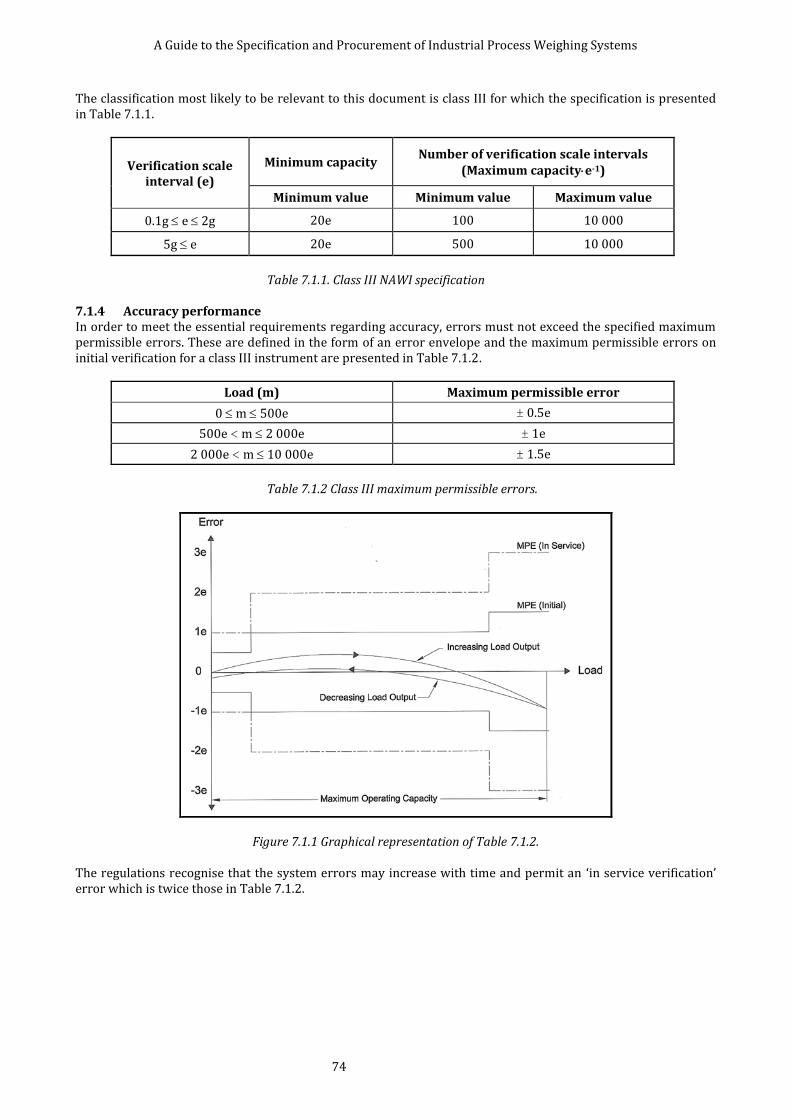
A Guide to the Specification and Procurement of Industrial Process Weighing Systems
74
The classification most likely to be relevant to this document is class III for which the specification is presented in Table 7.1.1.
Verification scale interval (e)
Minimum capacity Number of verification scale intervals
(Maximum capacitye-1)
Minimum value Minimum value Maximum value
0.1g e 2g 20e 100 10 000
5g e 20e 500 10 000
Table 7.1.1. Class III NAWI specification
7.1.4 Accuracy performance In order to meet the essential requirements regarding accuracy, errors must not exceed the specified maximum permissible errors. These are defined in the form of an error envelope and the maximum permissible errors on initial verification for a class III instrument are presented in Table 7.1.2.
Load (m) Maximum permissible error
0 m 500e ± 0.5e
500e < m 2 000e ± 1e
2 000e < m 10 000e ± 1.5e
Table 7.1.2 Class III maximum permissible errors.
Figure 7.1.1 Graphical representation of Table 7.1.2. The regulations recognise that the system errors may increase with time and permit an ‘in service verification’ error which is twice those in Table 7.1.2.

A Guide to the Specification and Procurement of Industrial Process Weighing Systems
75
7.1.5 Testing of NAWIs BS EN 45501:1994 [19] specifies the following tests: 1. Examination of documentation. 2. Comparison of the system with the documentation. 3. An initial examination, which includes examination of descriptive markings and arrangements for stamping. 4. Evaluation of performance, including: tests at zero load, weighing tests, tests of tare operation, eccentricity
testing, discrimination testing, sensitivity testing, evaluation of repeatability and creep testing. 5. The effect of influence factors including tilting, temperature and voltage variations. 6. Endurance tests. Although not all the tests are applicable, particularly for in-service verification, they are extremely detailed and the appropriate documentation and expertise should be consulted.

A Guide to the Specification and Procurement of Industrial Process Weighing Systems
76
7.2 SUMMARY OF IP CODES BASED ON BS EN 60529:1992+A2:2013 The following information is given for general guidance only. The reader should refer to the British Standard stated above. The degree of protection provided by an enclosure is indicated by the IP code with an arrangement shown below:
IP 2 3 C H
IP Ingress Protection, this is always stated.
2 First numeral, protection against ingress of solid bodies and against contact with live or moving parts.
3 Second numeral, protection against ingress of liquid.
C Additional letter, optional, protection against access to hazardous parts, such as back of hand, fingers, tool and wire.
H Supplementary information specific to high voltage apparatus, motion during water test, stationary during water test and weather conditions.
FIRST NUMERAL SECOND NUMERAL
0 No protection. 0 No protection.
1
Protected against access to hazardous parts with the back of a hand.
Protected against solid foreign objects of 50 mm diameter and greater.
1
Protected against vertically falling water drops. Vertically falling water drops shall have no harmful
effects.
2
Protected against access to hazardous parts with a finger.
Protected against solid foreign objects of 12.5 mm diameter and greater.
2
Protected against vertically falling water drops when enclosure is tilted up to 15.
Vertical falling drops shall have no harmful effects when enclosure is tilted at any angle up to 15 on either side of the vertical.
3
Protected against access to hazardous parts with a tool.
Protected against solid foreign objects of 2.5 mm diameter and greater.
3
Protected against spraying of water. Water sprayed at an angle up to 60 on either side
of the vertical shall have no harmful effects.
4
Protected against access to hazardous parts with a wire.
Protected against solid foreign objects of 1 mm diameter and greater.
4
Protected against splashing water. Water splashed against the enclosure from any
direction shall have no harmful effects.
5 Protected against access to hazardous parts
with a wire. Dust protected.
5 Protected against water jets. Water projected in jets against the enclosure from
any direction shall have no harmful effects.
6
Protected against access to hazardous parts with a wire.
Dust tight. 6
Protected against powerful jets. Water projected in powerful jets against the
enclosure from any direction shall have no harmful effects.
7
Protected against effects of temporary immersion in water.
Ingress of water in quantities causing harmful effects shall not be possible when the enclosure is temporarily immersed in water under standardised conditions of pressure and time.
8
Protected against the effects of continuous immersion in water.
Ingress of water in quantities causing harmful effects shall not be possible when the enclosure is continuously immersed in water under conditions which shall be agreed between manufacturer and user, but which are more severe than for numeral 7.
Some load cells may be specified as IP69K to ISO 20653, where “6” is “dust-tight” and “9K” is “Protected against high-pressure / steam-jet cleaning”.
A Guide to the Specification and Procurement of Industrial Process Weighing Systems
77
7.3 MODEL FORM FOR WEIGHING SYSTEM SPECIFICATION The model specification forms illustrated in this sub-section are intended to act as a framework to help a user or specifier to format a form that suits individual requirements. The specification form has been laid out in an order which correlates to the rest of this document. Each entry may be found in the index section from where the reader can find the relevant section of the document for further reference. Three examples of completed specifications are given, each being intended to illustrate how the various parameters that describe a process weighing system could be communicated. In reviewing these forms it should be remembered that they are written with the assumption that communication between user and supplier is two-way, and that both may write entries into the form. A user’s need may be fulfilled in different ways by different suppliers. It may be that the need is considered unrealistic in the view of a particular supplier, who may make alternative suggestions. Arriving at the final specification by which the system is procured should be a co-operative process, with both sides having an input. The information in the forms can and should be supplemented where possible by drawings to illustrate the text. It is recognised that there will also be specification information relating to contractual, commercial and quality management matters, it is recommended that these requirements should be referred to in “Additional Requirements” section and supplemented by appropriate documentation.

A Guide to the Specification and Procurement of Industrial Process Weighing Systems
78
7.3.1 Standard Form for Weighing System Specification
WEIGHING SYSTEM SPECIFICATION
Page 1 of 3
Project Ref. No.
Specification No.
Issue No.
Project title: Prepared by: Date:
Checked by: Date:
Approved by: Date:
Tag or Equipment Identification No.:
Schedule 3 (Legal for Trade) Application: Yes/No
Scope of Supply: (Give brief details of the system including the site location, type of process and material, if new or retrofit and any other salient points to give an overall summary of the requirement).
Supplementary Related Drawings or Documents:
User Data Supplier Data
1
GE
NE
RA
L
Field Environment Hazardous Area
2 Atmospheric Quality
3 Humidity
4 Temperature (Max/Min)
5 Wind Loading
6 Seismic Loading
7 Precipitation
8 Nuclear Radiation
9 Electrical Effects
10 Cleaning and Hygiene
11 System Performance
12 Method of Calibration
13 Special Requirements
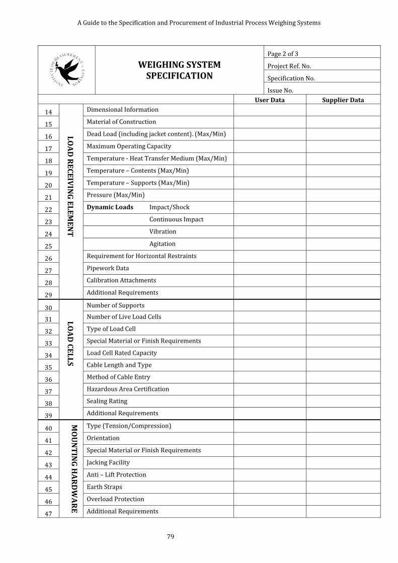
A Guide to the Specification and Procurement of Industrial Process Weighing Systems
79
WEIGHING SYSTEM SPECIFICATION
Page 2 of 3
Project Ref. No.
Specification No.
Issue No.
User Data Supplier Data
14
LO
AD
RE
CE
IVIN
G E
LE
ME
NT
Dimensional Information
15 Material of Construction
16 Dead Load (including jacket content). (Max/Min)
17 Maximum Operating Capacity
18 Temperature - Heat Transfer Medium (Max/Min)
19 Temperature – Contents (Max/Min)
20 Temperature – Supports (Max/Min)
21 Pressure (Max/Min)
22 Dynamic Loads Impact/Shock
23 Continuous Impact
24 Vibration
25 Agitation
26 Requirement for Horizontal Restraints
27 Pipework Data
28 Calibration Attachments
29 Additional Requirements
30
LO
AD
CE
LL
S
Number of Supports
31 Number of Live Load Cells
32 Type of Load Cell
33 Special Material or Finish Requirements
34 Load Cell Rated Capacity
35 Cable Length and Type
36 Method of Cable Entry
37 Hazardous Area Certification
38 Sealing Rating
39 Additional Requirements
40
MO
UN
TIN
G H
AR
DW
AR
E
Type (Tension/Compression)
41 Orientation
42 Special Material or Finish Requirements
43 Jacking Facility
44 Anti – Lift Protection
45 Earth Straps
46 Overload Protection
47 Additional Requirements

A Guide to the Specification and Procurement of Industrial Process Weighing Systems
80
WEIGHING SYSTEM SPECIFICATION
Page 3 of 3
Project Ref. No.
Specification No.
Issue No.
User Data Supplier Data
48 LO
AD
BE
AR
ING
S
TR
UC
TU
RE
Live Load Deflection
49 Type of Structure (Particularly in the region of the Load Cells)
50 Foundation Detail
51 Material of Construction
52 External Structural Influences
53 Ground Borne Dynamic Loads
54 Additional Requirements
55
JUN
CT
ION
BO
X
Electrical Connections
56 Hazardous Area Certification
57 Cable Entry
58 Cable Type and Connection
59 Maximum Cable Length to Weighing instrumentation
60 Special Material or Finish Requirements
61 Location (Including any Flammable Hazard)
62 Sealing Rating
63 Additional Requirements
64
WE
IGH
ING
INS
TR
UM
EN
TA
TIO
N
Location
65 Hazardous Area Certification
66 Atmospheric Quality
67 Ambient Temperature (Max/Min)
68 Supply Voltage and Frequency (Max/Min)
69 Output Signal (State Type)
70 Integral Display
71 Calibrated Range
72 Method of Mounting
73 Type of Enclosure
74 Sealing Rating
75 Additional Requirements
76 AD
DIT
ION
AL
IN
FO
RM
AT
ION
Documentation/Certification
77 Training Requirements
78 Spares Holding
79 Maintenance Programme
80 Additional Requirements

A Guide to the Specification and Procurement of Industrial Process Weighing Systems
81
7.3.2 Example 1. Ace Pet Foods, Expansion Project.
ACE PET
FOODS LTD. WEIGHING SYSTEM SPECIFICATION
Page 1 of 4
Project Ref. No. AA123/1
Specification No. XYZ120-E
Issue No. 1
Project Title: Pet Food Expansion Project
Prepared by: John Smith Date:8/5/98
Checked by: David Jones Date:21/5/98
Approved by: Anne Davis Date:22/5/98
Tag or Equipment Identification No.: V 124 Schedule 3 (Legal for Trade) Application: No
Scope of Supply: A new ribbon type-mixing vessel is to be installed in the moist cat food line at our production plant in Hertford. The supplier should provide, and calibrate all the necessary components to fulfil the duty outlined in the specification, but the installation both mechanical and electrical will be performed by our nominated sub – contractor. The supplier will be expected to provide our installation contractor with technical assistance to ensure a successful outcome. The ultimate responsibility to ensure that the specification will be met will lay with the weighing system supplier. Supplementary Related Drawings or Documents: 1) Drawing D342/1 General Arrangement of Mixer V124.
User Data Supplier Data
1 G
EN
ER
AL
Field Environment Hazardous Area N/A
2 Atmospheric Quality Wet and subject to Cleaning (*Note 1)
All field items in 304 Grade Stainless Steel
3 Humidity Field : R.H.100%
4 Temperature (Max/Min) 35/15 C
5 Wind Loading None
6 Seismic Loading None
7 Precipitation None
8 Nuclear Radiation None
9 Electromagnetic Fields Mobile Radio Units CE Marked (*Note 4)
10 Cleaning and Hygiene Food Production Area
11 System Performance 0.1% Comb. Error B.S.L.
0.1%of 1500kg(*Note 5)
12 Method of Calibration V.T.A.(Vendor to advise)
Weights (*Note 6)
13 Special Requirements 24hr.Operation (*Note 13)
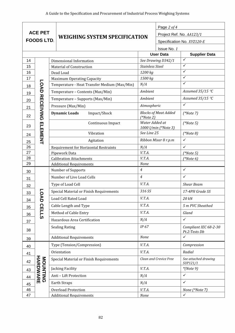
A Guide to the Specification and Procurement of Industrial Process Weighing Systems
82
ACE PET
FOODS LTD. WEIGHING SYSTEM SPECIFICATION
Page 2 of 4
Project Ref. No. AA123/1
Specification No. XYZ120-E
Issue No. 1
User Data Supplier Data
14
LO
AD
RE
CE
IVIN
G E
LE
ME
NT
Dimensional Information See Drawing D342/1
15 Material of Construction Stainless Steel
16 Dead Load 1200 kg
17 Maximum Operating Capacity 1500 kg
18 Temperature - Heat Transfer Medium (Max/Min) N/A
19 Temperature – Contents (Max/Min) Ambient Assumed 35/15 C
20 Temperature – Supports (Max/Min) Ambient Assumed 35/15 C
21 Pressure (Max/Min) Atmospheric
22 Dynamic Loads Impact/Shock Blocks of Meat Added
(*Note 2) (*Note 7)
23 Continuous Impact Water Added at
1000 l/min (*Note 3) (*Note 5)
24 Vibration See Line 25 (*Note 8)
25 Agitation Ribbon Mixer 8 r.p.m
26 Requirement for Horizontal Restraints N/A
27 Pipework Data V.T.A. (*Note 5)
28 Calibration Attachments V.T.A. (*Note 6)
29 Additional Requirements None
30
LO
AD
CE
LL
S
Number of Supports 4
31 Number of Live Load Cells 4
32 Type of Load Cell V.T.A. Shear Beam
33 Special Material or Finish Requirements 316 SS 17-4PH Grade SS
34 Load Cell Rated Load V.T.A. 20 kN
35 Cable Length and Type V.T.A. 5 m PVC Sheathed
36 Method of Cable Entry V.T.A. Gland
37 Hazardous Area Certification N/A
38 Sealing Rating IP 67 Compliant IEC 68-2-30
Pt.2:Tests Db
39 Additional Requirements None
40
MO
UN
TIN
G
HA
RD
WA
RE
Type (Tension/Compression) V.T.A. Compression
41 Orientation V.T.A. Radial
42 Special Material or Finish Requirements Clean and Crevice Free See attached drawing
SUP121/1
43 Jacking Facility V.T.A. *(Note 9)
44 Anti – Lift Protection N/A
45 Earth Straps N/A
46 Overload Protection V.T.A. None (*Note 7)
47 Additional Requirements None
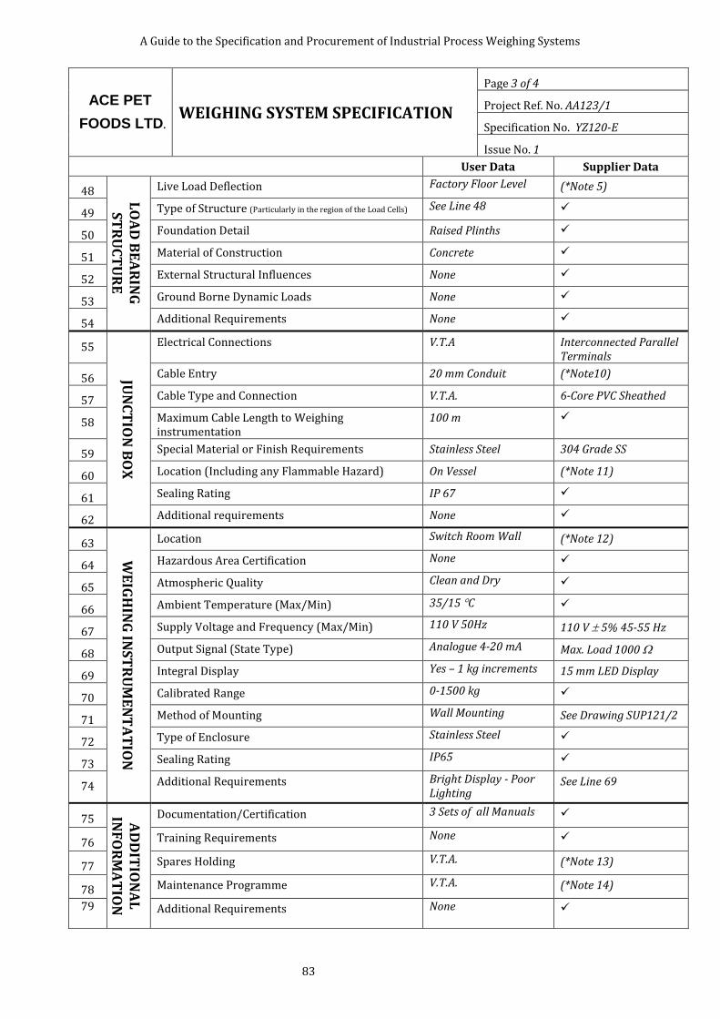
A Guide to the Specification and Procurement of Industrial Process Weighing Systems
83
ACE PET
FOODS LTD. WEIGHING SYSTEM SPECIFICATION
Page 3 of 4
Project Ref. No. AA123/1
Specification No. YZ120-E
Issue No. 1
User Data Supplier Data
48 LO
AD
BE
AR
ING
S
TR
UC
TU
RE
Live Load Deflection Factory Floor Level (*Note 5)
49 Type of Structure (Particularly in the region of the Load Cells) See Line 48
50 Foundation Detail Raised Plinths
51 Material of Construction Concrete
52 External Structural Influences None
53 Ground Borne Dynamic Loads None
54 Additional Requirements None
55
JUN
CT
ION
BO
X
Electrical Connections V.T.A Interconnected Parallel Terminals
56 Cable Entry 20 mm Conduit (*Note10)
57 Cable Type and Connection V.T.A. 6-Core PVC Sheathed
58 Maximum Cable Length to Weighing instrumentation
100 m
59 Special Material or Finish Requirements Stainless Steel 304 Grade SS
60 Location (Including any Flammable Hazard) On Vessel (*Note 11)
61 Sealing Rating IP 67
62 Additional requirements None
63
WE
IGH
ING
INS
TR
UM
EN
TA
TIO
N
Location Switch Room Wall (*Note 12)
64 Hazardous Area Certification None
65 Atmospheric Quality Clean and Dry
66 Ambient Temperature (Max/Min) 35/15 C
67 Supply Voltage and Frequency (Max/Min) 110 V 50Hz 110 V 5% 45-55 Hz
68 Output Signal (State Type) Analogue 4-20 mA Max. Load 1000
69 Integral Display Yes – 1 kg increments 15 mm LED Display
70 Calibrated Range 0-1500 kg
71 Method of Mounting Wall Mounting See Drawing SUP121/2
72 Type of Enclosure Stainless Steel
73 Sealing Rating IP65
74 Additional Requirements Bright Display - Poor Lighting
See Line 69
75 AD
DIT
ION
AL
IN
FO
RM
AT
ION
Documentation/Certification 3 Sets of all Manuals
76 Training Requirements None
77 Spares Holding V.T.A. (*Note 13)
78 Maintenance Programme V.T.A. (*Note 14)
79 Additional Requirements None
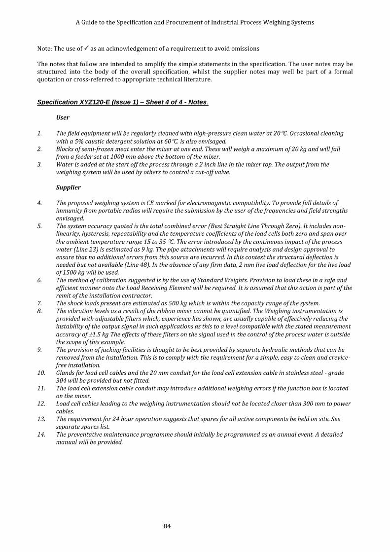
A Guide to the Specification and Procurement of Industrial Process Weighing Systems
84
Note: The use of as an acknowledgement of a requirement to avoid omissions The notes that follow are intended to amplify the simple statements in the specification. The user notes may be structured into the body of the overall specification, whilst the supplier notes may well be part of a formal quotation or cross-referred to appropriate technical literature. Specification XYZ120-E (Issue 1) – Sheet 4 of 4 - Notes.
User
1. The field equipment will be regularly cleaned with high-pressure clean water at 20C. Occasional cleaning with a 5% caustic detergent solution at 60C. is also envisaged.
2. Blocks of semi-frozen meat enter the mixer at one end. These will weigh a maximum of 20 kg and will fall from a feeder set at 1000 mm above the bottom of the mixer.
3. Water is added at the start off the process through a 2 inch line in the mixer top. The output from the weighing system will be used by others to control a cut-off valve.
Supplier
4. The proposed weighing system is CE marked for electromagnetic compatibility. To provide full details of
immunity from portable radios will require the submission by the user of the frequencies and field strengths envisaged.
5. The system accuracy quoted is the total combined error (Best Straight Line Through Zero). It includes non-linearity, hysteresis, repeatability and the temperature coefficients of the load cells both zero and span over the ambient temperature range 15 to 35 C. The error introduced by the continuous impact of the process water (Line 23) is estimated as 9 kg. The pipe attachments will require analysis and design approval to ensure that no additional errors from this source are incurred. In this context the structural deflection is needed but not available (Line 48). In the absence of any firm data, 2 mm live load deflection for the live load of 1500 kg will be used.
6. The method of calibration suggested is by the use of Standard Weights. Provision to load these in a safe and efficient manner onto the Load Receiving Element will be required. It is assumed that this action is part of the remit of the installation contractor.
7. The shock loads present are estimated as 500 kg which is within the capacity range of the system. 8. The vibration levels as a result of the ribbon mixer cannot be quantified. The Weighing instrumentation is
provided with adjustable filters which, experience has shown, are usually capable of effectively reducing the instability of the output signal in such applications as this to a level compatible with the stated measurement accuracy of 1.5 kg The effects of these filters on the signal used in the control of the process water is outside the scope of this example.
9. The provision of jacking facilities is thought to be best provided by separate hydraulic methods that can be removed from the installation. This is to comply with the requirement for a simple, easy to clean and crevice-free installation.
10. Glands for load cell cables and the 20 mm conduit for the load cell extension cable in stainless steel - grade 304 will be provided but not fitted.
11. The load cell extension cable conduit may introduce additional weighing errors if the junction box is located on the mixer.
12. Load cell cables leading to the weighing instrumentation should not be located closer than 300 mm to power cables.
13. The requirement for 24 hour operation suggests that spares for all active components be held on site. See separate spares list.
14. The preventative maintenance programme should initially be programmed as an annual event. A detailed manual will be provided.

A Guide to the Specification and Procurement of Industrial Process Weighing Systems
85
7.3.3 Example 2, Bulk Silo Company Silo Weighing Project.
Bulk
Supply
Company
WEIGHING SYSTEM SPECIFICATION
Page 1 of 4
Project Ref. No. W1234A
Specification No.SPEC1
Issue No. Rev.0
Project Title: Silo Weighing
Prepared by: A.Brown Date:01.07.99
Checked by: B. Jones Date:05.07.99
Approved by: C. Smith Date:09.07.99
Tag or Equipment Identification No.: WE-1234-A
Schedule 3 (Legal for Trade) Application: No
Scope of Supply:
A 100 tonne capacity, skirted silo is located outdoors, on the North East Scottish coast. The silo is, currently, installed directly onto a concrete pad. A structural steel “ring” will be provided, by the original silo supplier, to enable the silo to be weighed using four load cells. The weighing system will be used to continuously measure the contents of material in the silo and transmit the weight to a DCS system. The DCS will use the information for stock control and the control of the transfer of material from the silo to the process line. The silo is installed in a safe area free from any hydrocarbon and dust hazard. The material in the silo is hygroscopic and corrosive. The vendor is to provide all the equipment necessary to provide a successful weighing system. Installation of the equipment will be carried out by others under supervision of the vendor, who is also responsible for setting the equipment to work, calibration and ensuring that the equipment complies with all aspects of the specification. Supplementary Related Drawings or Documents: None
User Data Supplier Data
1
GE
NE
RA
L
Field Environment Hazardous Area Safe
2 Atmospheric Quality Coastal, Dusty,
Corrosive
All field items Stainless Steel
3 Humidity Field : 90 %
4 Temperature (Max/Min) 35/-10 C
5 Wind Loading N.E. Scotland
6 Seismic Loading None
7 Precipitation N.E. Scotland
8 Nuclear Radiation None
9 Electromagnetic Fields Mobile Comms. CE Marked (*Note 2)
10 Cleaning and Hygiene Hose
11 System Performance 0.5 % 500 kg (*Note 3)
12 Method of Calibration Material Delivery (*Note 4)
13 Special Requirements 24 hr. Operation (*Note 5)
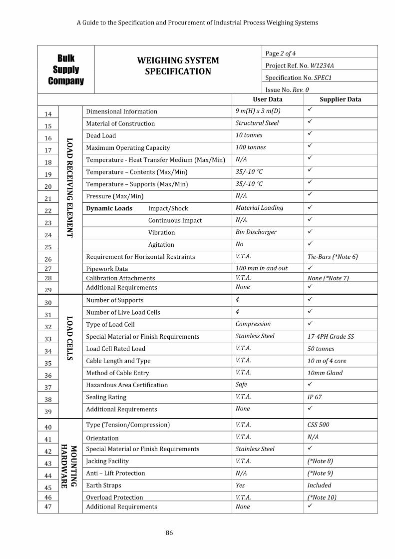
A Guide to the Specification and Procurement of Industrial Process Weighing Systems
86
Bulk
Supply
Company
WEIGHING SYSTEM SPECIFICATION
Page 2 of 4
Project Ref. No. W1234A
Specification No. SPEC1
Issue No. Rev. 0
User Data Supplier Data
14
LO
AD
RE
CE
IVIN
G E
LE
ME
NT
Dimensional Information 9 m(H) x 3 m(D)
15 Material of Construction Structural Steel
16 Dead Load 10 tonnes
17 Maximum Operating Capacity 100 tonnes
18 Temperature - Heat Transfer Medium (Max/Min) N/A
19 Temperature – Contents (Max/Min) 35/-10 C
20 Temperature – Supports (Max/Min) 35/-10 C
21 Pressure (Max/Min) N/A
22 Dynamic Loads Impact/Shock Material Loading
23 Continuous Impact N/A
24 Vibration Bin Discharger
25 Agitation No
26 Requirement for Horizontal Restraints V.T.A. Tie-Bars (*Note 6)
27 Pipework Data 100 mm in and out
28 Calibration Attachments V.T.A. None (*Note 7)
29 Additional Requirements None
30
LO
AD
CE
LL
S
Number of Supports 4
31 Number of Live Load Cells 4
32 Type of Load Cell Compression
33 Special Material or Finish Requirements Stainless Steel 17-4PH Grade SS
34 Load Cell Rated Load V.T.A. 50 tonnes
35 Cable Length and Type V.T.A. 10 m of 4 core
36 Method of Cable Entry V.T.A. 10mm Gland
37 Hazardous Area Certification Safe
38 Sealing Rating V.T.A. IP 67
39 Additional Requirements None
40
MO
UN
TIN
G
HA
RD
WA
RE
Type (Tension/Compression) V.T.A. CSS 500
41 Orientation V.T.A. N/A
42 Special Material or Finish Requirements Stainless Steel
43 Jacking Facility V.T.A. (*Note 8)
44 Anti – Lift Protection N/A (*Note 9)
45 Earth Straps Yes Included
46 Overload Protection V.T.A. (*Note 10)
47 Additional Requirements None
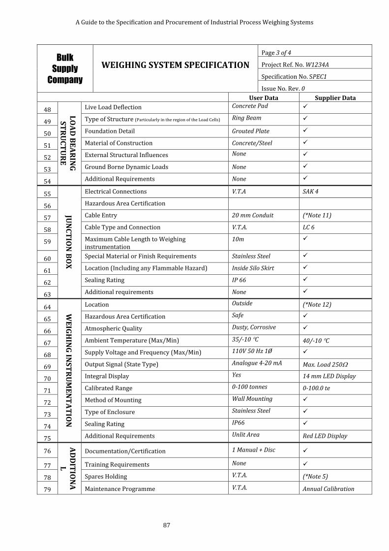
A Guide to the Specification and Procurement of Industrial Process Weighing Systems
87
Bulk
Supply
Company
WEIGHING SYSTEM SPECIFICATION
Page 3 of 4
Project Ref. No. W1234A
Specification No. SPEC1
Issue No. Rev. 0
User Data Supplier Data
48 LO
AD
BE
AR
ING
S
TR
UC
TU
RE
Live Load Deflection Concrete Pad
49 Type of Structure (Particularly in the region of the Load Cells) Ring Beam
50 Foundation Detail Grouted Plate
51 Material of Construction Concrete/Steel
52 External Structural Influences None
53 Ground Borne Dynamic Loads None
54 Additional Requirements None
55
JUN
CT
ION
BO
X
Electrical Connections V.T.A SAK 4
56 Hazardous Area Certification
57 Cable Entry 20 mm Conduit (*Note 11)
58 Cable Type and Connection V.T.A. LC 6
59 Maximum Cable Length to Weighing instrumentation
10m
60 Special Material or Finish Requirements Stainless Steel
61 Location (Including any Flammable Hazard) Inside Silo Skirt
62 Sealing Rating IP 66
63 Additional requirements None
64
WE
IGH
ING
INS
TR
UM
EN
TA
TIO
N
Location Outside (*Note 12)
65 Hazardous Area Certification Safe
66 Atmospheric Quality Dusty, Corrosive
67 Ambient Temperature (Max/Min) 35/-10 C 40/-10 C
68 Supply Voltage and Frequency (Max/Min) 110V 50 Hz 1Ø
69 Output Signal (State Type) Analogue 4-20 mA Max. Load 250
70 Integral Display Yes 14 mm LED Display
71 Calibrated Range 0-100 tonnes 0-100.0 te
72 Method of Mounting Wall Mounting
73 Type of Enclosure Stainless Steel
74 Sealing Rating IP66
75 Additional Requirements Unlit Area Red LED Display
76
AD
DIT
ION
AL
IN
FO
RM
AT
IO
N
Documentation/Certification 1 Manual + Disc
77 Training Requirements None
78 Spares Holding V.T.A. (*Note 5)
79 Maintenance Programme V.T.A. Annual Calibration
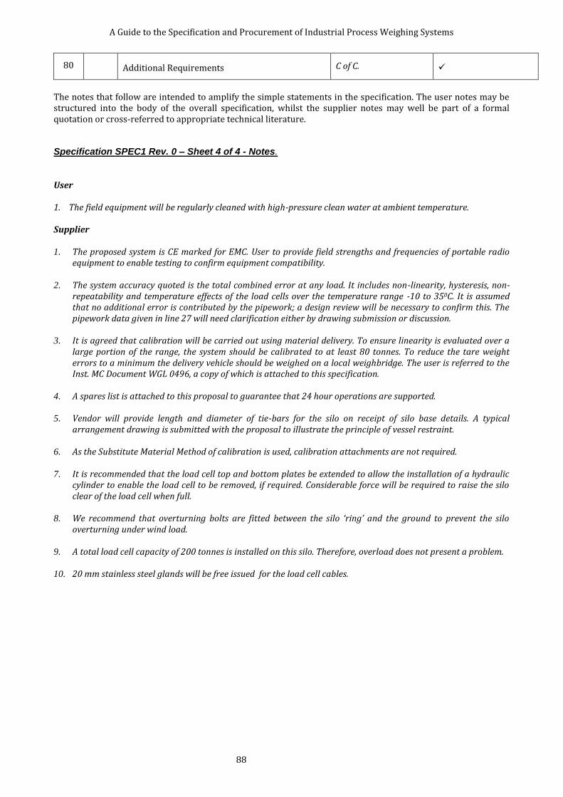
A Guide to the Specification and Procurement of Industrial Process Weighing Systems
88
80 Additional Requirements C of C.
The notes that follow are intended to amplify the simple statements in the specification. The user notes may be structured into the body of the overall specification, whilst the supplier notes may well be part of a formal quotation or cross-referred to appropriate technical literature. Specification SPEC1 Rev. 0 – Sheet 4 of 4 - Notes.
User 1. The field equipment will be regularly cleaned with high-pressure clean water at ambient temperature. Supplier 1. The proposed system is CE marked for EMC. User to provide field strengths and frequencies of portable radio
equipment to enable testing to confirm equipment compatibility. 2. The system accuracy quoted is the total combined error at any load. It includes non-linearity, hysteresis, non-
repeatability and temperature effects of the load cells over the temperature range -10 to 350C. It is assumed that no additional error is contributed by the pipework; a design review will be necessary to confirm this. The pipework data given in line 27 will need clarification either by drawing submission or discussion.
3. It is agreed that calibration will be carried out using material delivery. To ensure linearity is evaluated over a
large portion of the range, the system should be calibrated to at least 80 tonnes. To reduce the tare weight errors to a minimum the delivery vehicle should be weighed on a local weighbridge. The user is referred to the Inst. MC Document WGL 0496, a copy of which is attached to this specification.
4. A spares list is attached to this proposal to guarantee that 24 hour operations are supported. 5. Vendor will provide length and diameter of tie-bars for the silo on receipt of silo base details. A typical
arrangement drawing is submitted with the proposal to illustrate the principle of vessel restraint. 6. As the Substitute Material Method of calibration is used, calibration attachments are not required. 7. It is recommended that the load cell top and bottom plates be extended to allow the installation of a hydraulic
cylinder to enable the load cell to be removed, if required. Considerable force will be required to raise the silo clear of the load cell when full.
8. We recommend that overturning bolts are fitted between the silo ‘ring’ and the ground to prevent the silo
overturning under wind load. 9. A total load cell capacity of 200 tonnes is installed on this silo. Therefore, overload does not present a problem. 10. 20 mm stainless steel glands will be free issued for the load cell cables.

A Guide to the Specification and Procurement of Industrial Process Weighing Systems
89
7.3.4 Example 3. Fine Chemicals Inc., Reactor Vessel Weighing Project.
Fine
Chemicals
Inc.
WEIGHING SYSTEM SPECIFICATION
Page 1 of 4
Project Ref. No.: W1401
Specification No.: SPEC 2
Issue No.: Rev. 0
Project Title:
Reactor Vessel Weighing
Prepared by: A.Brown Date:01.08.99
Checked by: B. Jones Date:05.08.99
Approved by: C.Smith Date:09.08.99
Tag or Equipment Identification No.: 30-WE-1401
Scope of Supply: Schedule 3 (Legal for Trade) Application: No
A 40 tonne gross, 20 tonne capacity, reactor vessel is located outdoors, on the North West English coast. The vessel will be installed directly onto structural steel work A steel ‘ring’ will be provided by the reactor vessel supplier, to enable the vessel to be weighed using three load cells. The weighing system will be used to continuously measure the contents of fine chemicals in the vessel and transmit the weight to a DCS. The weighing controller is to be capable of accepting an auto-tare command from the DCS and actual weights batched will be reported to the DCS. The vessel is installed in a Zone 2 hazardous area, solvents are used in the internal cleaning process, external cleaning by high pressure hose, no dust hazard is present. The vessel incorporates a water jacket which is fed with a continuous flow of cold water leaving the vessel by an open connection. A hygienic installation is required. The vendor is required to provide all the equipment necessary to provide a successful weighing system. Installation of the equipment will be carried out by others under the supervision of the vendor who is also responsible for setting the equipment to work, calibration and that the equipment complies with all aspects of the specification. See note 1. Supplementary Related Drawings or Documents: None
User Data Supplier Data
1
GE
NE
RA
L
Field Environment Hazardous Area Zone 2 Intrinsic Safety
2 Atmospheric Quality Coastal All field items S.S.
3 Humidity Field : 50 % Occasional condensation
4 Temperature (Max/Min) 35/-10 C Standard equipment
5 Wind Loading N.W. England 25 m/sec.
6 Seismic Loading Negligible
7 Precipitation N.W. England
8 Nuclear Radiation None
9 Electromagnetic Fields Mobile Comms. CE Marked (*Note 2)
10 Cleaning and Hygiene High Pressure Hose
11 System Performance 0.05 % 20 kg (*Note 3)
12 Method of Calibration Water Meter (*Note 4)
13 Special Requirements Continuous ops. See note 5
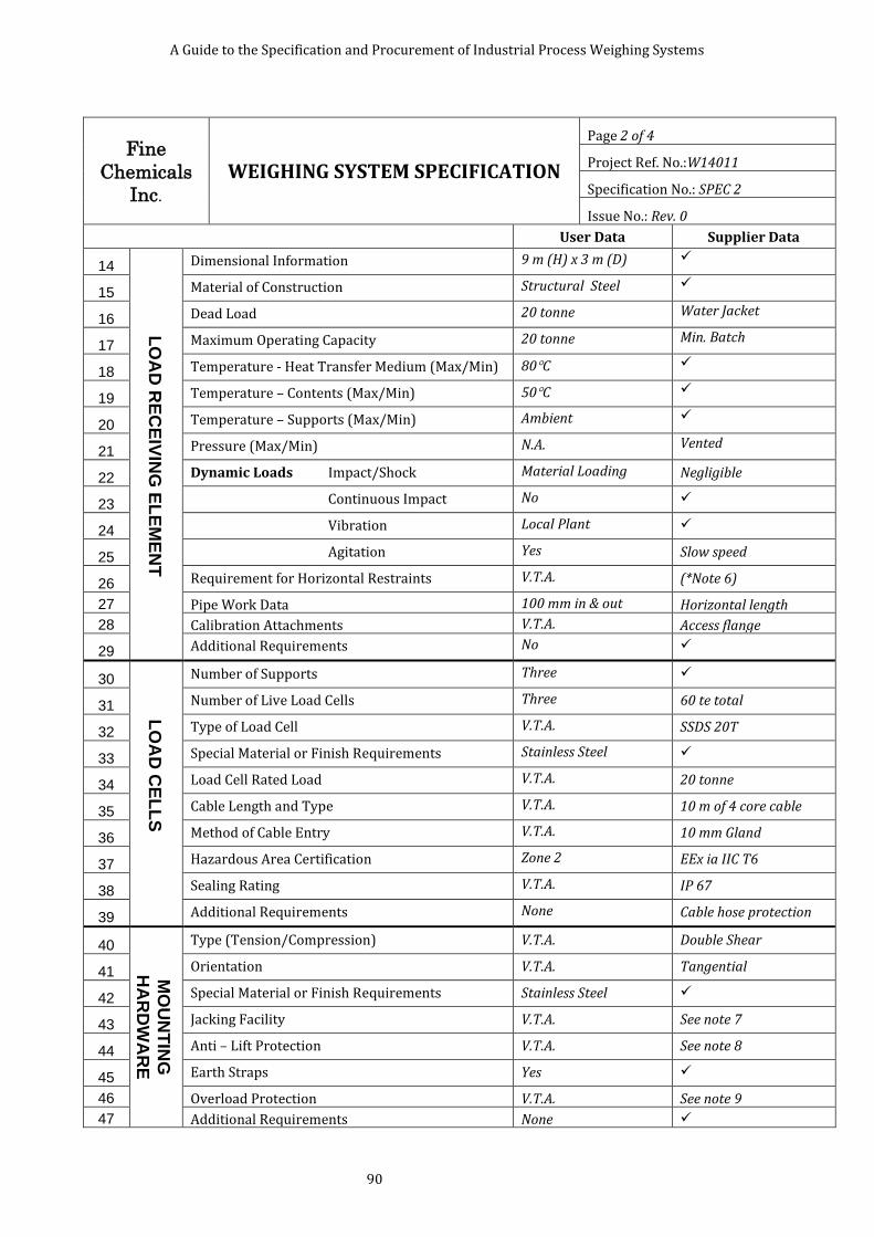
A Guide to the Specification and Procurement of Industrial Process Weighing Systems
90
Fine
Chemicals
Inc.
WEIGHING SYSTEM SPECIFICATION
Page 2 of 4
Project Ref. No.:W14011
Specification No.: SPEC 2
Issue No.: Rev. 0
User Data Supplier Data
14
LO
AD
RE
CE
IVIN
G E
LE
ME
NT
Dimensional Information 9 m (H) x 3 m (D)
15 Material of Construction Structural Steel
16 Dead Load 20 tonne Water Jacket
17 Maximum Operating Capacity 20 tonne Min. Batch
18 Temperature - Heat Transfer Medium (Max/Min) 80C
19 Temperature – Contents (Max/Min) 50C
20 Temperature – Supports (Max/Min) Ambient
21 Pressure (Max/Min) N.A. Vented
22 Dynamic Loads Impact/Shock Material Loading Negligible
23 Continuous Impact No
24 Vibration Local Plant
25 Agitation Yes Slow speed
26 Requirement for Horizontal Restraints V.T.A. (*Note 6)
27 Pipe Work Data 100 mm in & out Horizontal length
28 Calibration Attachments V.T.A. Access flange
29 Additional Requirements No
30
LO
AD
CE
LL
S
Number of Supports Three
31 Number of Live Load Cells Three 60 te total
32 Type of Load Cell V.T.A. SSDS 20T
33 Special Material or Finish Requirements Stainless Steel
34 Load Cell Rated Load V.T.A. 20 tonne
35 Cable Length and Type V.T.A. 10 m of 4 core cable
36 Method of Cable Entry V.T.A. 10 mm Gland
37 Hazardous Area Certification Zone 2 EEx ia IIC T6
38 Sealing Rating V.T.A. IP 67
39 Additional Requirements None Cable hose protection
40
MO
UN
TIN
G
HA
RD
WA
RE
Type (Tension/Compression) V.T.A. Double Shear
41 Orientation V.T.A. Tangential
42 Special Material or Finish Requirements Stainless Steel
43 Jacking Facility V.T.A. See note 7
44 Anti – Lift Protection V.T.A. See note 8
45 Earth Straps Yes
46 Overload Protection V.T.A. See note 9
47 Additional Requirements None
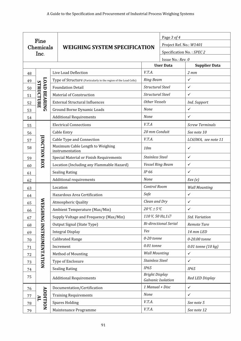
A Guide to the Specification and Procurement of Industrial Process Weighing Systems
91
Fine
Chemicals
Inc.
WEIGHING SYSTEM SPECIFICATION
Page 3 of 4
Project Ref. No.: W1401
Specification No. : SPEC 2
Issue No.: Rev. 0
User Data Supplier Data
48 LO
AD
BE
AR
ING
S
TR
UC
TU
RE
Live Load Deflection V.T.A. 2 mm
49 Type of Structure (Particularly in the region of the Load Cells) Ring Beam
50 Foundation Detail Structural Steel
51 Material of Construction Structural Steel
52 External Structural Influences Other Vessels Ind. Support
53 Ground Borne Dynamic Loads None
54 Additional Requirements None
55
JUN
CT
ION
BO
X
Electrical Connections V.T.A Screw Terminals
56 Cable Entry 20 mm Conduit See note 10
57 Cable Type and Connection V.T.A. LC6SWA, see note 11
58 Maximum Cable Length to Weighing instrumentation
10m
59 Special Material or Finish Requirements Stainless Steel
60 Location (Including any Flammable Hazard) Vessel Ring Beam
61 Sealing Rating IP 66
62 Additional requirements None Eex (e)
63
WE
IGH
ING
INS
TR
UM
EN
TA
TIO
N
Location Control Room Wall Mounting
64 Hazardous Area Certification Safe
65 Atmospheric Quality Clean and Dry
66 Ambient Temperature (Max/Min) 20C 5C
67 Supply Voltage and Frequency (Max/Min) 110 V, 50 Hz,1 Std. Variation
68 Output Signal (State Type) Bi-directional Serial Remote Tare
69 Integral Display Yes 14 mm LED
70 Calibrated Range 0-20 tonne 0-20.00 tonne
71 Increment 0.01 tonne 0.01 tonne (10 kg)
72 Method of Mounting Wall Mounting
73 Type of Enclosure Stainless Steel
74 Sealing Rating IP65 IP65
75 Additional Requirements Bright Display
Galvanic Isolation Red LED Display
76
AD
DIT
ION
AL
IN
FO
RM
AT
ION
Documentation/Certification 1 Manual + Disc
77 Training Requirements None
78 Spares Holding V.T.A. See note 5
79 Maintenance Programme V.T.A. See note 12

A Guide to the Specification and Procurement of Industrial Process Weighing Systems
92
80 Additional Requirements C of C O.K.
Specification SPEC 2 Rev. 0 – Sheet 4 of 4 - Notes. User 1. The field equipment will be regularly cleaned with high pressure clean water at ambient temperature. Supplier 2. The proposed system is CE marked for EMC. The equipment conforms to EN55022 together with associated IEC
801 Documents and European Council Directive 89/336/EEC. If the user’s portable communications equipment operates at field strengths and frequencies outside the range of the specifications above, details must be provided by the user to enable testing to confirm equipment compatibility
3. The system accuracy as quoted is the total combined error at any load. It includes for non-linearity, hysteresis,
non-repeatability and temperature effects of the load cells over the temperature range -10 to 35 C. It is assumed that no additional error is contributed by the pipe work, a design review will be necessary to confirm this. Structural steel deflection is assumed to be 2 mm for the live load. To achieve an accuracy of 0.05 % would involve considerable costs in design, manufacture and installation of pipe work and structure.
4. It is agreed that calibration will be carried out using a calibrated water meter. To ensure linearity is evaluated
over a large portion of the range, the system should be calibrated over the whole range of the system. A flange will be required to enable a hose to be connected to the vessel for calibration. User is to note that disposal of the calibration medium must be within their discharge consents.
5. A spares list is attached to this proposal to guarantee that continuous operations are supported. 6. Horizontal restraint may be necessary due to the action of the agitator, some restraint may be provided by the
load cells. Vendor will provide length and diameter of tie bars, if required, for the vessel on receipt of agitator power details.
7. It is recommended that the load cell top and bottom plates be extended to allow the installation of a hydraulic
cylinder to enable the load cell to be removed, if required. Considerable force will be required to raise the vessel clear of the load cell when full.
8. The load cell mounting unit incorporates an anti-lift feature in its design, this will be adequate for this
application. 9. A total load cell capacity of 60 tonne is installed on this vessel, therefore overload does not present a problem. 10. 20 mm stainless steel glands will be provided free issued for the load cell cables. 11. A three twisted pair, overall screened cable, single wired armoured cable, LC6SWA is recommended for
interconnection between the summation junction box and the weighing instrumentation. It will have a blue outer sheath to clearly indicate that it is used for IS circuits.
12. Regular visual inspection to ensure that there are no restrictions being imposed on the free movement of the
vessel. Calibration six months following the initial calibration and thereafter based on engineering intuition taking into account factors such as manufacturer’s recommendation, frequency and manner of use, environmental influences and the accuracy required. The manufacturer’s recommendation would be for six monthly intervals as the vessel is outside and subject to seasonal changes in temperature.

A Guide to the Specification and Procurement of Industrial Process Weighing Systems
93
8 REFERENCES
[1] ANSI A58.1 / ASCE 7-98, Minimum Design Loads for Buildings and Other Structures
[2] BS EN 1998 Eurocode 8, Design of structures for earthquake resistance
[3] A Structural Evaluation of Tank Support Applications Under Earthquake and Wind Loads, published by BLH Electronics, Inc.
[4] BS EN 60079-11:2012, Explosive atmospheres. Equipment protection by intrinsic safety "i"
[5] BS EN 60079-2:2007, Explosive atmospheres. Equipment protection by pressurized enclosure "p"
[6] BS EN 60079-15:2010, Explosive atmospheres. Equipment protection by type of protection "n"
[7] ILAC-G24 / OIML D 10, Guidelines for the determination of calibration intervals of measuring instruments
[8] A Code of Practice for the Calibration of Industrial Process Weighing Systems, WGC0496, published 1996, revised 2011, by the Institute of Measurement and Control
[9] BS EN 60529:1992+A2:2013, Degrees of protection provided by enclosures (IP code)
[10] OIML R 60, Metrological regulation for load cells
[11] BS 8422:2003, Force measurement. Strain gauge load cell systems. Calibration method
[12] BS EN 1991-1-4:2005+A1:2010, Eurocode 1. Actions on structures. General actions. Wind actions
[13] ASME B36.10M Welded seamless wrought steel pipe.
[14] Caesar II version 4.00 for Windows, courtesy of Fern Computer Consultancy Ltd, Ripley
[15] JCGM 200:2012, International Vocabulary of Metrology – Basic and General Concepts and Associated Terms, published by BIPM
[16] NPL Measurement Good Practice Guide No. 71, The Measurement of Mass and Weight
[17] Guide to the measurement of force, published 1998, revised 2013, by the Institute of Measurement and Control, ISBN 0 904457 28 1
[18] ASME B36.19 Stainless steel pipe
[19] BS EN 45501:1994, Specification for metrological aspects of non-automatic weighing instruments
[20] BS EN 60068-2-30:2005, Environmental testing. Tests. Test Db and guidance: Damp heat, cyclic (12 h + 12 h cycle)
[21] British Standard BS EN 50288-7:2005 Multi-element metallic cables used in analogue and digital communication and control – Part 7 Sectional specification for instrumentation and control cables.
[22] The Non-Automatic Weighing Instruments Regulations 2000 (S.I. 2000 No. 3236), as amended by The Non-Automatic Weighing Instruments (Amendment) Regulations 2008 (SI 2008/738)
[23] HB 10139:1997, Wind Loading Ready Reckoner for BS 6399-2:1997, published by BSI
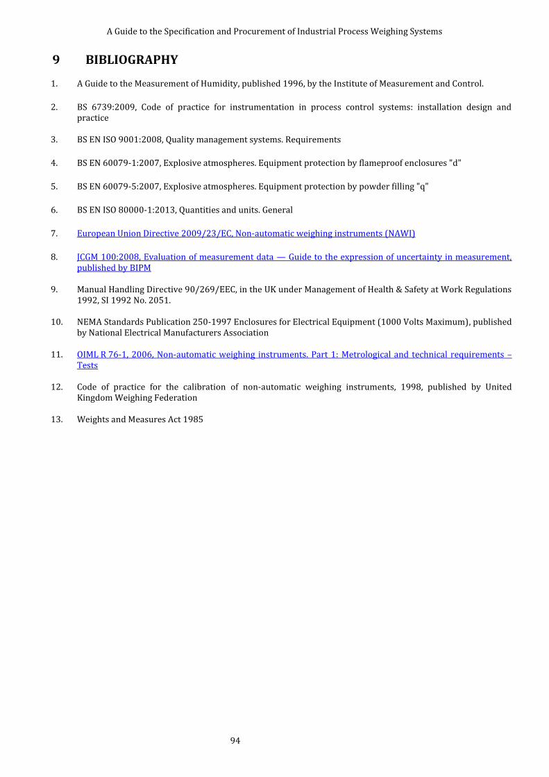
A Guide to the Specification and Procurement of Industrial Process Weighing Systems
94
9 BIBLIOGRAPHY 1. A Guide to the Measurement of Humidity, published 1996, by the Institute of Measurement and Control.
2. BS 6739:2009, Code of practice for instrumentation in process control systems: installation design and practice
3. BS EN ISO 9001:2008, Quality management systems. Requirements
4. BS EN 60079-1:2007, Explosive atmospheres. Equipment protection by flameproof enclosures "d"
5. BS EN 60079-5:2007, Explosive atmospheres. Equipment protection by powder filling "q"
6. BS EN ISO 80000-1:2013, Quantities and units. General
7. European Union Directive 2009/23/EC, Non-automatic weighing instruments (NAWI)
8. JCGM 100:2008, Evaluation of measurement data — Guide to the expression of uncertainty in measurement, published by BIPM
9. Manual Handling Directive 90/269/EEC, in the UK under Management of Health & Safety at Work Regulations 1992, SI 1992 No. 2051.
10. NEMA Standards Publication 250-1997 Enclosures for Electrical Equipment (1000 Volts Maximum), published by National Electrical Manufacturers Association
11. OIML R 76-1, 2006, Non-automatic weighing instruments. Part 1: Metrological and technical requirements – Tests
12. Code of practice for the calibration of non-automatic weighing instruments, 1998, published by United Kingdom Weighing Federation
13. Weights and Measures Act 1985
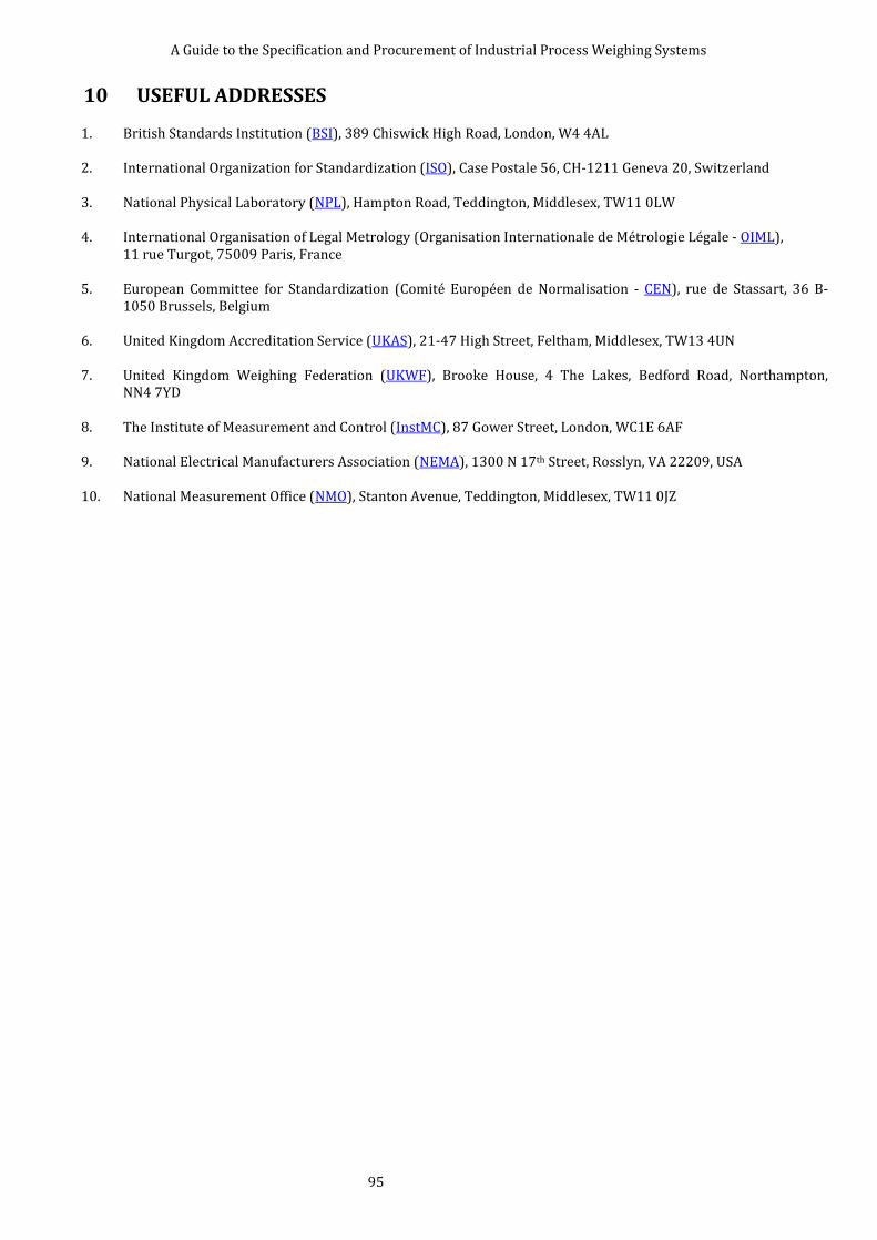
A Guide to the Specification and Procurement of Industrial Process Weighing Systems
95
10 USEFUL ADDRESSES 1. British Standards Institution (BSI), 389 Chiswick High Road, London, W4 4AL
2. International Organization for Standardization (ISO), Case Postale 56, CH-1211 Geneva 20, Switzerland
3. National Physical Laboratory (NPL), Hampton Road, Teddington, Middlesex, TW11 0LW
4. International Organisation of Legal Metrology (Organisation Internationale de Métrologie Légale - OIML),
11 rue Turgot, 75009 Paris, France
5. European Committee for Standardization (Comité Européen de Normalisation - CEN), rue de Stassart, 36 B-1050 Brussels, Belgium
6. United Kingdom Accreditation Service (UKAS), 21-47 High Street, Feltham, Middlesex, TW13 4UN
7. United Kingdom Weighing Federation (UKWF), Brooke House, 4 The Lakes, Bedford Road, Northampton, NN4 7YD
8. The Institute of Measurement and Control (InstMC), 87 Gower Street, London, WC1E 6AF
9. National Electrical Manufacturers Association (NEMA), 1300 N 17th Street, Rosslyn, VA 22209, USA
10. National Measurement Office (NMO), Stanton Avenue, Teddington, Middlesex, TW11 0JZ
A Guide to the Specification and Procurement of Industrial Process Weighing Systems
96
11 INDEX
A
absolute humidity · 34 aerodynamic factors (wind) · 43 agitation · 15, 25 anti-lift · See jacking facilities ATEX · 63 atmospheric quality · 33 austenitic stainless steel · 34
B
Bernoulli’s equation · 46 blanket pressure · 59 boot · 34 bump stop · 31
C
calibration · 8, 12, 13, 17, 18, 19, 20, 21, 22, 23, 24, 25, 53, 58, 73, 88, 92, 94
calibration frequency · 17 capacity, maximum operating · 8 capacity, minimum operating · 8 capillary action · 35 centre of gravity · 15, 16, 49, 70, 71 certification · 14 check rod · 8 cleaning · 25 concrete structure · 34 conduction · 29 continuous impact · 46 continuous material outflow · 47 convection · 29 COP · See company operating procedure Corrosion · 33
D
dead load · 8 dew point · 34 digital load cell · 8 DSEAR · 8 dummy load cell · 9
E
earth tremor · 69 earthing · 65, 66, 69 earthquake · 69 electrical storms · 68 error envelope · 74 essential requirements · 73 exothermic · 27
F
Fieldbus · 9 flexible coupling · 9 Force shunting · 33 four wire excitation · 31 four wire system · 32 free motion unit · 31
G
gaiter · 34 Galvanic barrier · 9 glycol · 29
H
hazardous area · 63 heavy rain · 37 horizontal restraining devices · 55 human factors · 12 humidity · 34 hygiene · 25
I
ice, accumulation of · 37 IEC · 9 impact · 44 impact of water · 37 IMS · 29 incremental error · 9 industrial methylated spirit · 29 influence quantity · 27 IP codes · 76 ISO · 9
J
jacking facilities. · 34
L
legal for trade · 73 lightning · 68 linear expansion coefficient · 28 live load · 9
M
magnification factor · 49 mass flow rate · 46 maximum operating capacity · 9 maximum permissible error · 17, 61
A Guide to the Specification and Procurement of Industrial Process Weighing Systems
97
method statement · 18 minimum operating capacity · 9 Minimum operating capacity · 9 mining equipment · 64 MPE · 17
N
NEMA · 94 non-mining equipment · 64 nuclear industry · 70 nuclear radiation · 71
O
OIML · 9, 23, 24, 36, 73, 93, 94 output resistance · 16, 17, 43 overload protection · 34 overturning moment · 39
P
pipework · 58 pivot · 10 precipitation · 36 pressure · 59 primary axis · 10 principal axis · 10
R
radiation, heat · 29 rated capacity · 10 relative humidity · 34 Richter Scale · 69
S
sandstorm · 33 scale interval, analogue · 10 scale interval, digital · 10 sealing · 14, 26, 33, 34, 35, 36, 66 seismic loads · 69
sensing · 10 shock load · 44 side force · 39 Simple Apparatus · 66 six wire system · 32 snow, accumulation of · 37 SOP · See standard operating procedure sprinkler systems · 26 Standard operating procedure · 18 storm · 68 structural movements · 51
T
temperature · 27 terminal velocity · 37 thermal shock · 27 thermal stress · 28 tie bar · See tie rod tie rod · 10 Tie rod · 55 transmitter · 10
U
UKAS · 95
V
vertical forces (due to wind) · 39 vibration · 48
W
water, accumulation of · 37 weighing structure · 10 wet powders · 34 wind bolt · 10 wind loads · 13, 38, 39, 43, 44, 69, 93
Z
Zener barrier · 10