Embed Size (px)
Citation preview

A Guide to Networksand Connectivity
www.commscope.com

1 The Need for Networks 2
2 Network Strategy 4
3 Alternative Network Configurations 6
4 Cabling Alternatives 11
5 Planning for Growth and Flexibility 15
6 Avoiding Interference 17
7 Standards, Categories and Regulations 19
8 Network Architecture, Design and Installation 24
9 Selecting a Supplier 30
10 Cost of Network Ownership 32
11 High-speed Networking 34
12 Cabling for the Multi-gigabit Era 36
13 Cabling for BAS, Security and
Other Low Voltage Systems 38
14 Wiring for Mobility 40
15 Real-time Infrastructure Management 42
Glossary of Terms 44

A guide to networks and connectivity
1
www.commscope.com
This guide is intended for those who need to know aboutcommunications infrastructure as part of their work, but whoare not necessarily specialists in this subject. Facilities andproperty managers, architects, design consultants anddepartmental heads are among those who now have toconsider connectivity issues, and will benefit from theinformation on these pages.
Cabling for data networks differs significantly from the morefamiliar power and telephone networks. An understandingof networks that can carry data and video, as well as voicetransmissions, will help you ensure that cabling installedtoday can meet the demands of tomorrow.
The guide focuses on key strategic and practical factors inplanning and implementing connectivity networks in theprivate or local network. Communications are rapidlybecoming the most important business resource as rapidadvances in computing and telecommunications arealtering the way people work, impacting overall productivity.As this happens, it is vital for organizations to have anetwork infrastructure that can turn these developments totheir advantage.
The various sections of this guide give an appreciation of theprinciples of connectivity and the issues involved. Crossreferences (in bold) to the Glossary section enable the readerto deal with the specialist infrastructure terminology that isso often a barrier to understanding the subject.
The priority in this publication is to provide information in aform that is easy to assimilate. It is not an exhaustive studyof communications networks.
Connectivity for Today and Tomorrow

1The need for networks
2
Network BasicsNetworks are a collection of systems and/or end pointdevices that allow sharing of information and resources suchas servers, workstations and peripherals. A properlydesigned and implemented network will give the speed andreliability of communication essential to an efficient system.
Networks should also conform to accepted national andinternational standards and be able to evolve with abusiness' changing needs.
Typical network
Workstation
Switch
Printer
Electronic equipment for tasks ranging fromcomputing and building security to environmentalcontrol, can produce greater benefits as part ofintegrated systems. The advantages of individualdevices working together grow as their numbersmultiply. At the same time, the challenges ofproviding the necessary links also increase.

A guide to networks and connectivity
3
www.commscope.com
Growing Need for NetworksDramatic growth in the use of computers has focusedattention on networks and cabling. Where once telephoneswere the only concern, managers now have to deal with thecomplex and rapidly changing requirements of computingand information systems.
In the past, it was common for desktop PCs to operate inisolation. Today, the vast majority of business PCs are part ofLocal Area Networks (LANs), enabling them to workproductively together.
LANs can connect PCs to servers and peripherals, orprovide links between transducers, cameras, monitors,sensors and almost any other electronic device. When suchlinks are made on an ad hoc basis, work areas can soonbecome cluttered with unidentified cabling, making fault-finding and basic maintenance more difficult.
Network TrendsThe use of networks and supported infrastructure isextending to new areas. The move from traditionalmainframe and minicomputer terminals and consoles toclient/server systems resulted in the replacement ofproprietary networks by open OSI - compliant networktransport systems. And many IT professionals are faced, forthe first time, with the need to develop cabling strategies forsecurity and building management systems, videoconferencing, multimedia information systems, Voice over IP(VoIP), Power over Ethernet (PoE), and new eBusinessapplications. And the evolution of networks continues at arapid pace, enabling network-wide applications to bedeployed that can take advantage of networked computingresources in new and innovative ways that can improveefficiency and productivity if properly deployed andmanaged, including peer-to-peer networks, clustering, andgrid computing.
A new aspect to enterprise networking is the introduction ofmobility. Wireless LANs (WLANs) have become popular notonly for residential use but also in the enterprise. A WLANprovides flexibility and improves the productivity of theworkforce. The integration of WLANs places additionalrequirements on network planning.
With the role of networks having expanded in this way,knowledge of networks and the infrastructure that enablesthem has become essential at all levels of management.

2Network strategy
4
Load Estimating and PlanningThe choice of network and cable types (described insections 4 and 5) depends on the types of devices to beconnected, their location and the way they are used. At theplanning stage, it is important to consider future as well aspresent requirements.
Load estimating has become increasingly difficult due to theunpredictable nature of bandwidth requirements associatedwith current technologies. Applications such as Internetaccess, email (and email attachments), VoIP, video, real timestreaming media and file transfers offer diverse challenges tothe network planner in the form of unpredictable trafficpatterns.
Target Life SpanThe target life cycle of an average cabling installation is up to 20 years (The ISO/IEC IS 11801 cabling standard forcustomer premises, states that a cabling system isanticipated to have a usable life in excess of 10 years). Over this time, several generations of networking hardwareand software will be installed, and network throughputrequirements will certainly increase, as will the importance of reliability and security.

A guide to networks and connectivity
5
www.commscope.com
Specifying a NetworkUnderspecifying networks and cabling systems is a commonerror. Since the expense and disruption of a prematurereplacement is so great, trying to cut corners at theinstallation stage may be unwise and frequently results inongoing rearrangements at a much higher financial cost andwith associated disruptions or delays in deployment ofservices.
Some key factors to consider in specifying a network may be summarized as follows:
• Usage patterns, including combined size and duration of peak loads for all applications
• Expected increase in bandwidth demands
• The number of users and anticipated growth
• Location of users and maximum distances from theselocations to the network switch
• Expected use of VoIP and PoE applications
• Expected use of wireless applications and anticipatedchanges in technology and applications
• The likely rate of change in users' locations (churn)
• Connectivity with current and future devices and software
• Space available for cable runs
• Total cost of ownership
• Regulations and safety requirements
• Importance of protection against loss of service and data theft

3Alternative network configurations
Network TypesThere are three main physical network topologies in commonuse. These topologies are the ring, bus and star.
Ring Networks - Ring networks, as the name suggests, havea continuous loop that passes every device. This ensuresthat signals from one device are seen by all other devices onthe ring. In a simple ring, a break in any part of the network,caused by a fault or system maintenance activity, will disablethe whole system. More advanced implementations havelargely overcome this problem. The Token Ring LAN is anexample of a ring network.
Bus Networks - The bus network connects devices along thelength of a cable, which is, essentially, a high-speedcommunications link. Devices can be removed from the buswithout disabling the rest of the system. The originalEthernet LAN is an example of a bus network.
Star Networks - Star networks incorporate many point-to-point links radiating from central equipment. In voicenetworks this could be the PABX and in data networks thiscould be the switch. Devices connected to atelecommunications outlet in a star network can be addedor removed easily without disturbing the rest of the network.
6

Ring network
Bus network
Star network
Switch
A guide to networks and connectivity
7
www.commscope.com

Physical topology
Switch
8
Topologies: Logical and PhysicalThe descriptions refer to the physical topologies ofnetworks. In practice, however, the physical topology of allthese networks is usually adapted to a star layout thatprovides a much more flexible method for moving users ofthe network. This is a major advantage when systems aregrowing or there is a significant degree of churn.
An example of this can be seen in the diagram above. Thesystem shown has the appearance of a star, but its logicaltopology remains a true ring, with the loop completed withinthe central switch. Networks based on star, bus and ringtype logical topologies all have their advocates, and the finalchoice largely depends on the application. The star physicaltopology, however, is now almost universally accepted withincommerce and industry.
Ethernet LANsThe original Ethernet networks worked over coaxial cable.The development of 10BASE-T, designed to operate overbalanced unshielded twisted pair (UTP) cable at datatransmission rates of 10 Mb/s, contributed to the widespreadadoption of Ethernet as the preferred LAN in most office andindustrial applications. Today, 100BASE-T (100 Mb/s) iscommonplace, and 1000BASE-T (1 Gb/s) is already beingdeployed on desktops, while 10 Gigabit Ethernet has emergedas the preferred option to support aggregation of desktopspeeds between switches in the backbone and forconnections to servers in data centers. 10 Gigabit Ethernetdeployments in Data Centers, backbones, and ultimately to thedesktop are expected to accelerate as equipment compliantwith the 10GBASE-T (10 Gb/s) standard for twisted pair cablingbecomes available.

A guide to networks and connectivity
9
www.commscope.com
100BASE-T and subsequent (faster) versions of Ethernethave a star physical topology. As with all LAN systems, PCsand other active devices connected to the network must beequipped with Network Interface Cards (NICs) or LAN-on-motherboard (LOM) technology.
Older protocols such as Asychronous Transfer Mode (ATM)and Fiber Distributed Data Interface (FDDI) are still in use,although they have been overtaken by the expansion ofEthernet into most areas of corporate networks.
ATMATM uses fast packet switching techniques to transmit delaysensitive data, over star networks, at up to 155 Mb/s fortwisted pair cabling and up to 2.5 Gb/s over optical cabling.
FDDIThe FDDI is a higher speed version of the Token Ring,operating over optical fibers at 100 Mb/s. FDDI systems canhave two complete fiber loops, providing a degree ofredundancy that is useful in critical applications.
Proprietary NetworksProprietary systems are a third common form of networking.Introduced before standards-based networks were established,proprietary systems were exclusive to a particular manufacturer.Among the most numerous were systems from IBM and Wang.Today however, proprietary networks have been replaced bystandards-based, open architecture networks.
Serial CommunicationAnother type of cabling that may be encountered is serialcommunications. This is often used to link terminals and PCsdirectly to minis, mainframes and peripherals at relatively lowspeed. This type of link is not true networking. However, serialconnections can be interfaced with structured cablingsystems and routed via switches and backbones. To do this, apassive adaptor or active interface device is required.
There are two principal forms of serial communications(asynchronous, and synchronous). Both types interconnectwith communications devices via their serial ports.
Wireless LANsWireless LANs, sometimes also called Wireless Ethernet,have a cell-based architecture where a Wireless AccessPoint (AP) serves as the base station supporting mobiledevices in that cell. APs are typically connected to a wiredEthernet backbone via a horizontal cable in a star topology.

Switch
Patchpanel
Equipment room
10
Backbones and Network LinksMultiple segments of a network, joined by a backbone cable,can create networks serving large areas, without excessivecabling. The backbone is a high-speed link that enablesseparate hubs or switches to work together as a unit. If abackbone fails, the individual subnets may continue tooperate autonomously.
Backbone cables can be coaxial, balanced twisted pair oroptical fiber cable. Generic cabling standards, however,recommend the use of multimode fiber or balanced twistedpair cables in the backbone.
To form large networks, individual LANs of any type can belinked together via backbone cables, bridges or routers. WithEthernet, switches are often grouped in a single room forsecurity and convenience. In this case, the backbones are short,and the system is referred to as a collapsed backbone network.
Refurbish or Replace?In many installations, there will be the option to install acompletely new network or refurbish one already in place. The latter alternative usually offers major savings, but itsviability depends on the existing cabling and the approachchosen for the new network. However, ad hoc networks,which use mixed cabling for historic or cost reasons, haveinherent drawbacks.
Today's structured cabling systems are available with rangesof adaptors for interconnection with all major hardwaretypes. These will allow established systems, as well as newerones, to benefit from the latest cabling techniques.

4Cabling alternatives
A guide to networks and connectivity
11
www.commscope.com
Importance of CablingCabling is a key component of any networked system, sodecision makers should be prepared to commit up to 15%of the total cost in this area. Failures in badly designed andimplemented cabling are both common and expensive, soinvestment in high quality cabling and network design iseasily justified.
Cable ChoiceThe equipment connected to a network and thecommunications load it imposes are key factors in cablechoice. There are, however, other considerations:
• Maximum distance between network switches and endpoint devices
• Space available in ducting and floor/ceiling cavities
• The levels of Electromagnetic Interference (EMI) present
• Cable fire risk assessment (regulations and insurerrequirements)
• Likely changes in equipment served by the system and the way it is used
• Level of resilience required
• The required life span of the network
• Restrictions on cable routing that dictate cable bend radius
• Existing cable installations with potential for reuse

Building to building backbone
Shielded (STP) Foil screened (FTP)
Unshielded twisted pair (UTP) Optical fiber
Cable AlternativesTaking the points on the previous page into account, the firstcabling decision is the choice between UTP, shielded and/orfoil screened cable types, optical fiber or a combinationof these.
Cables other than optical fiber invariably have copperconductors insulated and protected by one or more plasticsleeves. These are often formed into cables containinganything from two to hundreds of pairs. The higher paircount cables are usually used in the backbone andespecially for traditional voice and very low speed dataapplications.
The maximum lengths over which these cables can run inbackbone and horizontal (Hub-to-desk) applications arespecified in cabling standards such as the InternationalStandard ISO/IEC IS 11801. These are summarized in thediagram below:
Building 1
2000mcampus
backbone
Building 2
90m horizontal
300m building backbone
12
A guide to networks and connectivity
13
www.commscope.com
It is important to note that these maximums apply to all media.They do not take into account the performance differencesbetween cable types and transmission protocols used by thenetwork. In practice, maximum cable lengths will depend on theapplication, the type of network used (e.g. 1000BASE-T) and thecable's quality. Good cable suppliers and installers will advise ona cabling system's capabilities in a particular network.
Size RestrictionsIt is important to check the space available for cable runs beforemaking decisions on cable type. The size, weight and flexibilityof shielded and screened cables depends on whether foil orbraided sleeving is used, and how many conductors they have.These factors, together with the shielding/screening material,will also determine the cable's resistance to EMI. It is, therefore,very important to consider the method of shielding/screeningbefore choosing such cables.
Shielded CablesShielded cables, referred to as STP, use an expensive andbulky construction consisting of individually shielded twistedpairs with an additional overall shield. This is a robust andbulky cable that is far less flexible than unshielded types.
Foil Screened Cables, usually referred to as FTP or ScTP, areconstructed of four twisted pairs with an overall foil sleeve.FTP cables can be more compact than STP, but generallyhave much lower resistance to EMI than STP types.
Both shielded and screened cables have metal sleeves thatmust be grounded well to cancel the effect of EMI on thesignal carried by the conductors, requiring special groundingand termination considerations.
Unshielded Twisted Pair CableAdvances in UTP cabling over the last 15 years have enabledit to carry data reliably at speeds of up to 10 Gb/s. This allowsthe use of more cost effective cabling in applications thatwere previously considered the reserve of other media types(i.e. coaxial cable, optical fiber). UTP has become thepreferred media worldwide for transmission to the desktop.The latest developments in UTP cabling technology, coupledwith advances in networking equipment, that now enable UTPcabling to carry data at speeds up to 10 Gb/s ensure that UTPwill continue to be the preferred copper media worldwide.
UTP cables minimize EMI by closely matching eachconductor of a cable pair such that any interference iscancelled out. This is known as a balanced circuit.

14
Balance of CircuitsIn a perfectly balanced circuit, the sum of noise voltagesinduced in the conductors is zero, so there is no interferencewith the signal being transmitted. UTP cable is designed tosupport cost-effective balanced transmission.
Shielded cable can be less balanced due to the presenceof the shield, thus shield integrity and grounding are vital. High quality UTP cables achieve a well-balanced circuitwithout a need for shielding the entire circuit.
Alien Crosstalk and 10 Gigabit Transmission on UTPCompared to the requirements up to 1 Gb/s, the IEEE10GBASE-T standard for 10 Gigabits over twisted paircabling places additional demands on the cablinginfrastructure, including the need to support extendedfrequencies and the requirement to minimize Alien Crosstalk.Alien Crosstalk is the coupling of signals between adjacentcabling links or channels. While traditional and cumbersomeshielding techniques may be used to minimize AlienCrosstalk, developments in UTP cabling technology havealready been shown to achieve the required performanceand reliability, and it can be expected that the marketpreference towards UTP will continue.
Optical Alternative For high-speed applications in backbone cabling and overextended distances, optical fiber is the most commonlyused alternative. Optical fiber occupies little space and isvery robust but remains more expensive to install andconnectorize than other cable types. Additionally, the opticalfiber transmission equipment carries a significant premiumover the copper alternatives.
Most optical fiber cable used in LANs within the building isof the multimode type. Compared to the higher performancesinglemode fiber used in campus deployments, multimodeallows for the use of less expensive electronic equipmentand is easier (less expensive) to install and connectorize.
Since the optical fiber transmission equipment carries asignificant premium over the copper alternatives, in mostnetworks optical fiber is used for backbones (where higherspeeds or longer distances are required), while balancedUTP provides the link to the desktop. Because optical fibertransmits signals via light waves, it is inherently resistant tovirtually all forms of electronic interference.

5Planning for growth and flexibility
A guide to networks and connectivity
15
www.commscope.com
Major cable manufacturers specify their products andwarranties assuming a 15- or 20-year life. Over this time,change is both inevitable and impossible to predictaccurately. The only solution is to specify a network that isinherently able to accommodate change, growth and morebandwidth-intensive applications.
Future ReadinessIn normal circumstances, a new network should not becomethe factor that restricts system upgrades within the 20-yearbuilding refurbishment cycle. Well-designed cabling systemswill have the potential to handle data 10-15 times faster thanmost commonly installed LANs. This allows new networkingtechnology to be introduced without replacing the cabling.
The applications it serves define a network's minimumspecification. However, in some situations where Category5e cable is considered adequate, it often makes sense toinstall better cabling (such as cabling with significantperformance margin to Category 6, or Category 6A cabling)to provide for future needs.
With the shift from proprietary to open computer systemshas come a move from proprietary to standards-basedcabling. The latter can serve many different types of devices,ranging from PCs and printers to video cameras andthermostats or Wireless Access Points.
Standards-Based CablingStandards-based cabling is a major advance, offering usersfreedom to connect equipment from a variety of suppliers. It also gives users the potential to employ the same networkto serve several separate systems, for example, telephones,computers and building controls.

16
Saturated WiringThe flexibility offered by standards-based cabling isenhanced with the use of saturated wiring. This is theinstallation of sufficient cabling and outlets in a work area tomaximize flexibility of the location for devices connected tothe network. IT departments then have similar freedom inhow they arrange their work areas.
Wiring for MobilityStandards-based cabling is also required to support mobileapplications such as WLANs today. A Wired for Mobilityoutlet grid, with a cabling network end point at regularintervals, makes the wired infrastructure ready for growth andnew wireless infrastructure requirements in the future. Withthe Wired for Mobility grid in place, there is maximumflexibility for adding wireless infrastructure devices in a costeffective way.
Structured CablingStandards-based cabling and saturated wiring are centralelements in structured cabling, an approach pioneered bySYSTIMAX® Solutions, from CommScope. This uses an opensystem approach, supporting major proprietary and non-proprietary standards and protocols. SYSTIMAX Solutions™uses balanced UTP and optical fiber cabling deployed in astar topology and terminated with standard outlets.
Use of standards-based structured cabling, forming amodular network, makes it easy to extend or change asystem with minimum disruption to users. In high growthcompanies, structured cabling allows smooth, controlledexpansion, with addition of new equipment and cable runs atreduced incremental cost.
Network ComponentsPatch panels located in each zone of a building or campusallow PCs, peripherals, network switches and other devicesto be connected and disconnected quickly. In companieswith high rates of churn, this gives considerable savings. When new cable is laid and outlets added, UTP structuredcabling simplifies the task through its use of standardcomponents throughout. UTP cabling is easier to handle andinstall than shielded or coaxial types.

6Avoiding interference
Every active electrical and electronic device has potentialto produce electromagnetic flux that can disrupt networkcommunications. This problem has increased alongside thegrowth in the use of electronic equipment. Both cableselection and cable routing are vital in safeguardingcommunications against interference.
In addition to the potential for interference from externalsources, the active pairs in a multi-pair cable can interferewith each other. This is known as crosstalk.
There are two methods of measuring crosstalk performance,pair-to-pair and PowerSum. The pair-to-pair method onlymeasures the maximum interference caused by any othersingle active pair in the cable. When many pairs in a multi-pair cable are active, the loss of performance will be greaterthan that indicated by the pair-to-pair method.
PowerSum is a more realistic way of measuring crosstalk.It is based on the measurements taken when all pairs in amulti-pair cable are active. For cables containing more thanfour pairs, PowerSum is the only appropriate method fortesting crosstalk performance.
External Noise Sources All network components, including switches, PCs andcabling must be designed to perform adequately in thepresence of external noise. Particular care is needed whencabling components are produced by differentmanufacturers.
A guide to networks and connectivity
17
www.commscope.com

18
Routing of cable should conform to cable manufacturers'recommendations and should always avoid potential sourcesof interference. Potential sources of EMI are lift motors,automatic doors and air-conditioning units. The older thisequipment, the more likely it is to produce EMI. Closed metalconduits and ducting will give cabling extra protectionagainst sources of EMI that cannot be remedied or avoided.
Where shielded cabling is used, correct termination andgrounding of the shield at patch panels and outletconnectors is vital. The potential benefits of the shield mustbe weighed against complications related to grounding andsafety. Any lack of shield integrity can render the potentialbenefits totally ineffective, and large currents may flow in theshield due to improper grounding.
When deploying twisted pair cabling for 10 Gb/stransmission, particular attention must be paid to AlienCrosstalk, the coupling of signals from adjacent links ofchannels. Recent advances in UTP cabling technology allowUTP cabling to minimize Alien Crosstalk and are an integralpart of emerging standards for Category 6A and Class E
A
cabling.
For most indoor cabling environments, balancedtransmission over UTP offers excellent protection againstexternal noise.
In particularly electromagnetically hostile or sensitiveenvironments, use of optical fiber cabling may be the onlyalternative.
EMC Regulations Both the installer and system user are responsible forensuring their networked systems have electromagneticcompatibility (EMC) with other electronic devices. EuropeanEMC Directives have been mandatory in all European Unioncountries from 1 January 1996, and penalties againstnetwork owners are specified for non-compliance. In Asia,many countries have adopted requirements set by IECCISPR for EMC compliance. In the US, the FCC maintainsstringent directives for EMC compliance.
Reputable installers will ensure that cabling specifications,routing and ducting are designed to eliminate interferenceproblems. Some manufacturers also provide warranties onthe EMC performance of certified installations using theircabling.
7Standards, categoriesand regulations
Cabling standards not only encompass communicationsperformance, they also cover areas ranging from routing andfire resistance to EMC. The greatest value of cablingstandards is in defining terminology and general approaches.They are not intended to provide a detailed specification forbuilding a network.
ISO/IEC and TIA/EIABoth the ISO/IEC and TIA/EIA standards organizations havedefined generic cabling systems suitable for medium and largeoffices. Details of these can be found in the ISO/IEC IS 11801standard for Customer Premises Cabling and TIA/EIA 568B.
ISO/IEC IS 11801, TIA/EIA 568B and the European version,EN 50173-1, are all key standards for cabling installation. These cover similar areas, but use different approaches toconformity. ISO/IEC IS 11801 is a global standard that hasevolved to meet the needs of all geographic areas. As aresult, some of its requirements are very broad.
Cable Categories TIA/EIA 568B and ISO/IEC 11801 specify several cablingcategories. The first two categories are suited only to voiceand data communications up to 4 Mb/s and are seldom usedin data networking applications. While both TIA/EIA andISO/IEC refer to components in terms of “categories”,TIA/EIA also uses “categories” for end-to-end channelperformance, while the ISO/IEC standard refers to the end-to-end performance in terms of “Classes”.
Category 3 cabling is generally regarded as suitable only fornetworks operating up to 16 Mb/s using active equipment.Primary usage is for backbone cabling to support voice (but not VoIP). ISO/IEC refers to the end-to-end Category 3channel as a Class C channel.
A guide to networks and connectivity
19
www.commscope.com

20
Category 4 cable was developed to support communicationsat 16 Mb/s over runs up to 100 meters, but is nowconsidered obsolete. ISO/IEC never introduced a matchingspecification for Category 4.
Category 5 cabling was designed to support applications upto 100 Mb/s. Reliable support for 1 Gb/s requires additionalperformance specifications, and existing installations may notcomply. Category 5 cabling is now also considered obsolete.A superseded edition of ISO/IEC 11801 referred to the end-to-end Category 5 channel as a Class D channel.
Category 5e (Enhanced Category 5) is an upgrade to Category5 specifications that was targeted as minimally compliantsupport of Gigabit Ethernet (1000BASE-T). The maximumfrequency specified for Categories 5 and 5e is 100 MHz. 1Gb/s signalling is accomplished via PAM5 encoding schemetransmitted over all cable pairs. ISO/IEC refers to the end-to-end Category 5e channel as a Class D channel.
Category 6 cabling was designed with a significantimprovement in bandwidth, which is nearly double thebandwidth of Category 5e for robust support of GigabitEthernet (1000BASE-T) over the maximum frequencyspecified of 250 MHz. Category 6 cabling is alsorecommended if mid-span PoE is required to be supportedas an application since the additional connectionsintroduced by the mid-span equipment may have adetrimental effect on the crosstalk and return lossperformance of the end-to-end 'channel'. ISO/IEC refers tothe end-to-end Category 6 channel as a Class E channel.
Category 6A cabling is designed to meet or exceed therequirements of 10 Gb/s Ethernet (10GBASE-T). It extendsthe cabling bandwidth beyond Category 6 by specifying thefrequency range out to 500 MHz and includes the AlienCrosstalk specifications that are vital for the support of 10Gb/s Ethernet. ISO/IEC is developing the Class E
A
specification, offering better performance than Category 6Afor certain parameters.
Category 7 cabling is specified only in ISO/IEC 11801 andCENELEC EN50173-1 (Class F), but not in TIA-568B. It isspecified to a frequency of 600 MHz and requires the use ofbulky and expensive individually paired shielded cables. The connector for Category 7 is a complex switched version ofan RJ45 that does not seem to have gained significant share inthe Category 7 market. A non-RJ45 version is also allowedwhen the customer is prepared to give up compatibility with

Transmission characteristics of UTP
Low 100KHz 1MHz 16MHz20MHz100MHz 250MHz 500MHz
Category 6A
Category 6
Category 5
Category 4
Category 3
A guide to networks and connectivity
21
www.commscope.com
RJ45 plugs. Class F is not expected to gain wide marketacceptance and its market share was predicted to reach0.4% worldwide by 2006. Class FA specifications to 1000MHz have recently been added in ISO/IEC.
Cabling for 10GBASE-TThe IEEE developed the 10GBASE-T standard with the intentof targeting the installed base of Category 6/Class Ecabling. However, although Category 6/Class E cabling isthe minimum requirement in the 10GBASE-T standard,achievable distances over Category 6/Class E cabling arehighly dependent on the Alien Crosstalk environment as wellas the cabling performance at frequencies not specified forCategory 6/Class E. Shielded Category 6/Class E cablingmay exhibit improved Alien Crosstalk, but without anormative specification and without the necessary standardsspecifications for higher frequency performance.
Guidelines for the verification of 10GBASE-T requirementshave been developed by EIA/TIA (TSB-155) and ISO/IEC (TR 24750), but do not provide improved specifications forCategory 6/Class E and are not intended for newinstallations. Achieving useful distances over UTP is likely torequire multiple mitigation steps ranging from unbundling ofcables to component replacement, since the Category6/Class E cabling standards fall considerably short of the10GBASE-T requirements and do not specify Alien Crosstalk.

22
For new installations, Category 6A or Class EA cablingguarantees 10GBASE-T support to 100 m over UTP. Sincethe international Class E
Aspecification is more stringent,
cabling for new installations intended to support 10GBASE-Tshould be specified to meet the Class E
Arequirements.
Network Standards Two major LAN types, Ethernet and Token Ring, are alsodefined by standards. The IEEE, the Institute of Electricaland Electronic Engineers, sets standards for theimplementation of Ethernet defined through its 802.3Committee. Token Ring standards were developed by the802.5 Committee.
The work of the IEEE committees aims to ensure a highdegree of consistency and interoperability between systemsimplemented by different suppliers. Conformance with theirstandards is important to network buyers, since non-standard elements can lead to disruption and extra costwhen networks are modified or extended.
The evolution and widespread acceptance of Ethernet hasensured that the 802.3 Committee continues to be active,having developed Ethernet specifications up to 10 Gb/s overlaser-optimized 50 micron multimode fiber, and currentlyworking on a 10 Gb/s specification for 4 connector twistedpair cabling channels over 100 m.
Fire PreventionStandards that are of particular practical interest to networkusers are those relating to fire. These differ from country tocountry, but invariably cover both flame spread andsmoke emission.
Conforming to a minimum local standard will ensure that fireofficers do not order removal of a network. However, the key isto install 'the right cable in the right environment' so as toreduce risk to fire hazard. Data cables that conform to thehighest North America and international standards should beinstalled in areas where the risks of fire occurrence andbusiness loss/interruption are the highest, for example in datacenters and communication rooms. These cables have veryhigh fire retardance (and low smoke emission) that will preventthe fire from spreading to other parts of the room or building.

A guide to networks and connectivity
23
www.commscope.com
In relation to this impact of a widespread fire, any extra costin buying cable to the highest standard is minimal.Specifying cable with low fire retardance can incur higherinsurance premiums. Insurers often set additionalrequirements to complement statutory building regulations.These increased standards required by the insurers aredesigned not only to provide safety for the people affected inthe fire, but also to protect the assets of the business, tominimize the cost of fire damage to buildings and theircontents, and to improve business continuity.
In Europe, a common approach to attempt to minimize theimpact of fire in cabling is to use Low Smoke Zero Halogen(LSZH) cabling. When this cable burns, less smoke will beproduced (compared with traditional PVC cables) to hinderevacuation of the building. However, the use of LSZHmaterials does not ensure that the cables will have lowflammability. Cables compliant with the IEC 60332 Part 3specifications offer better fire performance than the lessexpensive IEC 60332 Part 1 compliant cables. A much betterfire-performing alternative (commonly used in North America,and now also included in the Construction Product Directivein Europe) is to use plenum rated (also known as enhancedfire performance) cable, which is a low smoke and highly fireretardant cable. In North America, plenum rated cable haslong been recognized as a safer cable and is defined by theNational Fire Protection Association in the National ElectricalCode (NFPA 70), which is revised and published every3 years.

8Network architecture, design and installation
Once network configuration and cabling types are decided,there remains the practical task of designing and installingthe system. The first step, deciding network architecture, isusually a straightforward task. Examples of networkarchitecture for typical buildings and sites are shown in thediagram on page 25.
Collapsed BackbonesVariations on the typical architectures are possible. Forinstance the backbones may be collapsed so that servers,switches and patch panels can be contained within acompact, secure area. This can save space and improve thesystem's physical security.
RedundancyWhere systems are mission critical, redundant backbonesand risers may be needed to implement a mesh designednetwork which will give the required level of system faulttolerance. In these situations, duplicate pathways should be as far fromeach other as possible.
Physical LimitationsDecisions on the type of cable needed for risers,backbones, horizontal runs and saturated wiring will havebeen made at an early stage of planning. At installation,design and planning stages, it is important to work within thephysical limitations of the chosen cable type.
24

Network architecture
Cable Routing Cable manufacturers will specify minimum bend radii andmaximum pull-through forces. They will also give advice onproximity to sources of heat, vibration, EMI and pathway fill.
Routing Diagram A comprehensive cable routing diagram must be producedbefore installation begins. This will be a guide to installersand a reference point for future maintenance, expansion andfault tracing.
Cable Labeling The diagram should be cross referenced to physical labelson each cable run. Producing plans and labeling can beundertaken by the installer or handled by an in-housesystems department. A number of software packages areavailable to assist in these tasks.
Installation and AccessNetworks should be designed for easy installation andaccess while giving cables adequate support and protection.Manufacturers' guidelines are designed to ensure that allthese criteria are met. They also take into account nationaland international standards applying to cable pathways. It is,however, the installer's responsibility to ensure that therequirements of building codes and standards are met in full.
Patch panel Patch panel
Switch
A guide to networks and connectivity
25
www.commscope.com

26
Alternative methods of cable support and protection include:
• Underfloor Ducts
• Access (Raised) Floors
• Conduit
• Trays and Wireways
• Ceiling Distribution
• Perimeter Raceways
Conduits and Conduit Ceiling DistributionConduit and ceiling distribution are usually implementedaccording to industry-based standards. EIA/TIA 569B, forinstance, specifies that conduit sections should be amaximum of 30 m long and have no more than two 90degree bends between pull points. Inside bend radii must besix times conduit diameter, or at least ten times for conduitsover 50 mm.
Wireways Using suitable equipment and procedures when installingcable will minimize tension and avoid damage. Wireway andraceway manufacturers guidelines and code requirementsmust also be followed in determining cable fill for thesetypes of pathway.
Cable Support Ceiling distribution, conduits, trays and other pathwayhardware can be used above suspended ceilings.Alternatively, the cable can be hung loosely using J-hooks,rings or other means of suspension, at spacings of no morethan 1.5 meters. Unless they are designed for the purpose,ceiling tiles, rails and supports should not carry cables.Communication cables should not be tied to power cablesfor support.
Large bundles of over 140 cables may require specialattention to prevent overstressing cables at the bottom of thebundle.
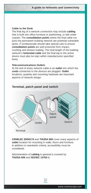
Terminal, patch panel and switch
Switch
A guide to networks and connectivity
27
www.commscope.com
Terminal
Outlet
Patchpanel
Cable to the DeskThe final leg of a network connection may include cablingthat is built into office furniture or partitioning, or laid undercarpets. The consolidation points where the final cable runjoins the permanent building network are potential vulnerablespots. IT professionals should take special care to ensureconsolidation points are well protected from impact,crushing and tension loading. The total length of the buildingnetwork's horizontal cable and the final leg to the activedevice must also be kept within manufacturers specifiedlimits.
Telecommunications Outlets At the end of every network cable is an outlet into which thecords connected to the devices are plugged. Outletlocations, quantity and mounting hardware are importantaspects of network design.
CENELEC EN50174 and TIA/EIA 569 cover many aspects ofoutlet location for mounting in walls, floors and furniture. In addition to standards criteria, accessibility must beconsidered.
Administration of cabling in general is covered byTIA/EIA 606 and ISO/IEC 14763-1.

Moving patch cords
Location A
Location B
Patchpanel
Location B
Location A
28
High quality and good design are of special importance inoutlets and connectors. Over the course of a network's life,these may be connected and disconnected many thousandsof times, and any weakness will result in a poor connection.Bad connections and poor connector performance are, byfar, the greatest cause of cable network faults.
In shielded cable, the quality, location and integrity ofgrounding and bonding connections are particularlyimportant and often difficult to achieve and monitor, and anyloss of shielding integrity will have an effect on the cable'sresistance to EMI.
Between the outlets at the periphery of a network and theswitches at its center there will invariably be patch panels.These allow cable runs to be connected and disconnectedvery quickly, simply by moving patch cords.

A guide to networks and connectivity
29
www.commscope.com
Patch PanelsIn a network that never changed, patch systems would notbe necessary. In practice, every network is subject tomovement of people or provision of new services, and it isthe patch panel that allows this to take place quickly withminimum effort and disruption. Patch panels also make iteasier to detect and bypass network faults.
Patch panels are generally located near network hubs in aposition that minimizes the total cabling distance to outlets.
Power over Ethernet (PoE)More and more network endpoint devices (e.g. IP phones,Wireless Access Points, IP cameras) are able to be poweredover the standards-based copper cabling, so that no localpower for these end devices is required. The DC power isinjected into the data pairs of the horizontal cabling by aPoE-enabled switch (end-span) or to the pairs of thehorizontal cabling by a mid-span PoE device. PoE has beenstandardized in the IEEE 802.3af. Mid-span PoE devices areavailable with 6, 12 and 24 ports. A new PoE Plusspecification is in development to support the additionalcurrent requirements of devices such as Pan-Tilt-Zoomcameras and dual radio access points..
Eliminating the labor costs associated with contracting anelectrician to run wiring for new AC outlets, savessignificantly on the installation cost of the end devices.
Overall, PoE simplifies the installation of the network,improves the speed of installation, and ultimately saves timeand money. In addition to powering end devices, the mid-span PoE device can provide continuous service duringpower outages when utilizing the same centralized UPS thatprovides back-up power to the network.

9Selecting a supplier
30
In practice, the most important network decision for mostusers is the selection of a supplier. Besides implementing thenetwork, good suppliers can offer valuable advice andinformation.
Since networking is a specialist subject, many organizationscall on suppliers and independent consultants to help withnetworking specifications and strategy. In this situation, it isvital to select a supplier or consultant with skills andexperience that can be trusted.
Selection CriteriaSome of the questions that should be asked of a cablingsupplier are given in the list below.
• Size - does the supplier have the resources to handlethe job?
• Skill set - does the supplier have all the necessary skillsand have installers received adequate training from thecabling manufacturer?
• Quality - does the supplier have quality processes inplace to cover all aspects of design, materials, installationand testing, e.g. as per ISO 9001:2000 and TL 9000certification?
• Warranty - does the supplier provide a comprehensivewarranty backed by the cabling system manufacturer?Does the warranty cover the applications that will run onthe network as well as the cabling components? Doesthe warranty cover labor to replace any defectivecomponents? Is the warranty based on fully documentedtesting by a qualified organization?

A guide to networks and connectivity
31
www.commscope.com
• Materials - will cable and components be to the higheststandards and produced by a single manufacturer? Are allthe cables and components quality tested and verified byindependent test laboratories with follow-up verificationprograms?
• Authorization - is the supplier fully trained and authorizedby the cabling manufacturer?
Suppliers Suppliers authorized by leading cabling manufacturers arerequired to meet comprehensive technical and businessstandards. They are also provided with full training innetwork planning and installation.
Systems installed by authorized suppliers, and subsequentlycertified, are usually backed by manufacturers warranties,ranging from five to 20 years. It is important to note that notall suppliers using cabling from a particular manufacturer areauthorized. Even a network exclusively using onemanufacturer's product will not be guaranteed by themanufacturer unless it is installed by an authorized supplier.

10Cost of network ownership
Total cost of ownership is a key factor when assessing bidsto supply and install a network. Since a network can beexpected to have a 20-year life, the accumulation of re-occurring costs and the cost of upgrades can equal orexceed the original capital investment.
Network EvolutionAdding, removing and changing devices connected to thenetwork is usually the greatest cost after initial installation.Structured cabling systems were developed to reduce thiscost, allowing new sections to be added to a network withminimum effort.
The Ad hoc AlternativeThe alternative to integrated structured cabling is ad hoccabling. This can take various forms, some of which fallwithin the definition of structured cabling, but none can bedescribed as integrated. Different types of cablingcomponents can be linked in ad hoc cabling to create asystem that functions, but may result in high operating costsand frequent communications problems.
Ad hoc cabling systems usually have a lower initial cost thanfully integrated, structured cabling systems but do not offerthe benefits of a guarantee backed by a single manufacturer.This includes the guarantee of the cabling systems' EMCperformance. It is unlikely that ad hoc cabling systems willbe fully tested to prove EMC performance and there is thensome debate as to who is responsible for the EMCconformance.
32

A guide to networks and connectivity
33
www.commscope.com
CompatibilityMaintenance costs in ad hoc cabling systems can be higher,since new components must be obtained from multiplesources, creating extra overheads. There are also greaterrisks of incompatibility as the components may not havebeen tested together as a system.
Incompatibility problems may only manifest themselves whenchanges are made to the system or higher speed networksare implemented.
Network FaultsOperational faults are potentially an even bigger problem andone that is difficult to predict. Fault-finding can beparticularly expensive in badly designed and implementednetworks. Full documentation of paths and easy access to cables andconnectors is essential to minimize the cost of preventiveand corrective work.
WarrantiesThe quality of a network's warranty is the best assurancethat system faults will not result in unexpected costs. Ideally,the warranty should cover the full 20-year life expectancy ofa cabling system and cover the cabling components from end-to-end, as well as the labor that may be required toreplace any defective components.
To avoid disputes in the event of a claim, the warrantyshould cover the cabling components and the applicationsthe system has been designed to support. Only cablingsuppliers that have fully tested and documented supportableapplications on their systems can offer such a warranty withconfidence.
A network designed and implemented by a companyauthorized by the manufacturer of all its components willhave fewer areas of doubt in its warranty. In these situations,there can be no argument as to which particular supplier isresponsible for a fault.

11High-speed networking
34
Preparing for the FutureDemand for networking capacity is growing relentlessly. New communications-dependent systems are being installedand these are used more intensely than their predecessors.Even greater communication demands are created by a newgeneration of multimedia applications. These requiresimultaneous video, voice and data transmission that canexceed 100 Mb/s or even 1 Gb/s for each workstation.Network technologies and data rates consideredunwarranted only a few years ago must now be considered adistinct possibility for the future of any network.
Various LAN and WAN technologies and approaches havebeen developed in response to increased demand forcommunications and the Ethernet family (includingspecifications spanning from 10 Mb/s to 10 Gb/s) has been themost successful technology in the LAN. The shift to 10 Gigabitnetworking is already apparent in backbone implementations,and in the increased deployment of storage area networks(SANs). As bandwidth demands continue, the next migrationwill be 40+ Gb/s for enterprise and data center backbones.
Gigabit Ethernet LANs are rapidly migrating from fast Ethernet to GigabitEthernet in the horizontal, due to increased bandwidth demandsand reduced prices for 1 Gb/s network equipment and interfacecards. The worldwide acceptance of Category 5e and Category6 UTP cabling has facilitated the migration to 1000BASE-T nowunder way and it can be expected that Category 6A UTP cablingwill facilitate the migration to 10GBASE-T in the near future.
Switched LANsA dramatic increase in network performance has beenachieved by implementing switched LANs, which is nowcommonplace in today's enterprise networks. Switchingimproves performance between workstations and servers,but places additional demand on building backbones.

A guide to networks and connectivity
35
www.commscope.com
10 Gigabit EthernetNetwork backbones and data centers are already migratingto 10 Gigabit Ethernet over optical fiber. The type of opticalfiber selected for the backbone will determine the type,complexity and cost of the networking equipment that maybe deployed. OM3 laser-optimized 50 micron multimodefiber utilizing low cost VCSEL technology provides a moreeconomical alternative to singlemode fiber implementations.The 10GBASE-T standard for twisted pair cabling isexpected to accelerate deployment of 10GBASE-T withlower cost technology that will eventually deliver 10 Gigabitsto the desktop.
Storage Area NetworksThe data explosion experienced in the LAN has also resultedin increased requirements for server-to-server and server-to-storage networks. Data rates of 10 Gigabit are common inthese networks, which extend to the building backbone.Commonly deployed for storage area networks, FiberChannel technology operates at various data rates up to10 Gb/s, and the InfiniBand™ architecture has beendesigned for wire speeds of 2.5 Gb/s and beyond. The latestimprovement in signaling rates has extended the availablebandwidth to up to 120 Gb/s.
Grid ComputingGrid computing makes "spare" desktop CPU horsepoweravailable across the network to large jobs that require it. There are many scientific applications that need thecomputing power of arrays, but up to now the cost of asupercomputer or a massively parallel array was prohibitive.Grid computing is a technique that effectively provides thehorsepower "across the network" to support these kinds ofapplications. Grid computing is highly dependent upon veryfast interconnections among all of the participatingcomputing platforms. Present successful implementations ofthis are found in the form of clusters of servers that are setaside and tied together, often in the data centers, via a fastfiber or other types of optical interface. The network is being populated right now with workstationsthat offer unprecedented computing power. The simpleability to harness these common appliances together with avery fast, cost-effective interconnection scheme would makeit possible to deploy grid computing across an organization.

36
12Cabling for the multi-gigabit era
With no end in sight to the bandwidth explosion, and giventhe current growth rates, Gigabit LANs are the norm formany organizations. Gigabit desktop connections and 10Gigabit backbones are becoming the common requirementfor many organizations while 10 Gb/s UTP connections willbe initially implemented in data centers, low rise backbonesand for mission critical applications. Although the exacttiming of the migration to higher speeds for a givenorganization is not easily predicted, the selection of asuitable infrastructure today can determine the ability toreact in a speedy and cost-effective manner whenever theneed arises.
In anticipation of future needs, SYSTIMAX® Labs hasdeveloped leading-edge connectivity solutions to enable thesmooth and cost-effective migration to the high-speedapplications of the 10 Gigabit Era.
Horizontal CablingIn the horizontal subsystem, cabling that meets Category 6/Class E specifications offers inexpensive insurance againstdemands up to 1 Gb/s. The SYSTIMAX GigaSPEED®
Solution was the blueprint that drove the standardsdevelopments of Category 6/Class E.
If 10 Gigabit Ethernet is expected to be deployed to thedesk within the lifetime of the cabling installation, UTPcabling that meets the specifications for Class E
Aand
Category 6A offers unparalleled application support overUTP. The SYSTIMAX GigaSPEED X10D Solution quicklybecame the blueprint for the new cabling channelspecifications early in their development.

Building BackboneIn the riser backbone, a combination of multimode andsinglemode fiber cables may be required. The LazrSPEED®
Solution offers next generation support for 10 gigabittechnology, virtually eliminating the need for singlemodefiber in buildings.
Campus BackboneSince the campus backbone often provides the mostdifficult installation conditions, network planners need toconsider the highest capacity cable plant available.Singlemode fiber is the recommended media. TheSYSTIMAX TeraSPEED™ singlemode solution provides awide range of options for outdoor environments.
Media RecommendationsSYSTIMAX Solutions media recommendations based onthese developments are summarized in the diagram below.
Campus backboneSinglemode for
100+ Gb/s TeraSPEED
Riserbackbone
Multimodefor
10 Gb/sLazrSPEED
HorizontalCategory 6/Class E for 1+ Gb/s GigaSPEED XL
Category 6A/Class EA for 10 Gb/s GigaSPEED X10DMultimode for 10 Gb/s LazrSPEED
A guide to networks and connectivity
37
www.commscope.com

13Cabling for BAS, security andother low voltage systems
38
Recent advances in technology and adoption of industry-widestandards have resulted in efforts to improve communicationsbetween the various low-voltage systems in commercial officebuildings. Over a decade of industry evolution has resulted ina compelling business case to integrate these systems onto acommon cabling system, or onto a common IP-basednetwork, and the development of the ANSI/TIA/EIA-862Building Automation Systems Standard for CommercialBuildings. This standard endorses the star-based designapproach of using UTP cabling for all low-voltage buildingsystems and permits common closets and pathways for allfive of the low-voltage building systems including officeautomation, HVAC, Fire/Life/Safety, Security and EnergyManagement Systems. An international version of this NorthAmerican standard is under development at this time.
Deployment of a cabling system in accordance with TIA-862 can result in reduced installation cost and time todeployment and, perhaps more importantly a drasticreduction in ongoing management expenses related to,cabling-related moves, adds and changes.
Early data “networks” were not generally interconnected orcompatible, and utilized dissimilar cabling andcommunications protocols that prevented the exchange ofdata without complicated and expensive hardware. Their evolution and integration has been led by thedeployment and market dominance of Ethernet and UTP-based structured cabling, accompanied by significantimprovements in performance and reduction in total systemcost. The same trend is already apparent in the area ofBuilding Automation, and the benefits of the integratedcabling approach should be considered when planning for anew cabling infrastructure.
Most buildings feature between 10 to 46 low voltage systems,each requiring its own control, management and monitoring.Without a common infrastructure that can link them together,

IBIS cabling
SD SD
TTR
TR
TR
ERMC MR
EF
HCP
HCP
Coverage Area
Windows
Coverage Area
Coverage Area Coverage Area
EF Entrance facility
ER Equipment room
HC Horizontal cross-connect
HCP Horizontal connection
point
TR Telecommunications
room
A guide to networks and connectivity
39 www.commscope.com
these dozens of systems can create a lifetime accumulation ofunnecessary cost. But with a single backbone supporting all ofthese systems—from security to lighting, from HVAC tocommunications—building operations can become highperforming and cost-effective.
Intelligent Buildings—and their requisite infrastructures—arequickly becoming the new standard for owners/operators andtenants who want high-performing, easily-managed, efficientspaces. Deploying an Intelligent Building InfrastructureSolution (IBIS) facilitates convergence of a building’s systems,from Building Automation Systems and CommunicationsSystems, to video surveillance and access control, over thesame, common standards-based cabling infrastructure,providing an enhanced level of efficiency and cross-systemperformance.
MR Mechanical room
MC Main cross-connect
SD Smoke detector (a BAS device)
T Thermostat (a BAS device)
BAS outlet
Camera (a BAS device)

14Wiring for mobility
40
As wireless infrastructure technology continues to evolve,
the wired infrastructure that supports the wireless network
needs to be proactively designed to future-proof the network
investment. In order to be prepared for wireless technologies
that potentially have a much smaller range and require dense
wireless infrastructure (i.e. dense spacing of the Access
Points), pre-wiring the enterprise with a relatively dense grid
of outlets future-proofs the wired infrastructure.
This is the 'Wired for Mobility outlet grid.
Initially, a subset of the installed outlets will be used to
support today's IEEE 802.11a/b/g APs for data. When new
technologies become available, moving or adding APs
becomes relatively simple and cost effective. In addition to
the wireless infrastructure, pre-wiring based on the grid
future-proofs for the rollout of other IP based applications
such as BAS, IP cameras, security or other applications.

A guide to networks and connectivity
41
www.commscope.com
The ISO/IEC Technical Report 24704 “Customer premises
cabling for wireless Access Points” specifies minimum
cabling requirements for wireless coverage, and
recommends an overlay “honeycomb” grid for TOs to be
placed in the ceiling in cells with 12 meter (40 ft) radius as
per the drawing below. When the outlets are placed in a
more rectangular fashion, the recommended distance
between the outlets is 20 meters.
Grid of telecommunications outletsfor wireless coverage areas
D = 20 m (max)

15Intelligent Infrastructure Solutions
42
It is clear that today, more than ever, the network is the heartof the enterprise. The cabling infrastructure is its centralnervous system. Typically, more than 20% of networkconnections are moved, added, changed or disruptedannually. Traditionally, the physical connectivity layer isadministered through manual re-arrangement of cablingconnections, and this makes it susceptible to human errorsthat can prove costly. In today's world of completeintegration of data networks into corporate bu There arenumerous network management software products availableon the market to enable management of networkcomponents. These sophisticated programs easily integratecomponents from a multitude of vendors and are capable ofmonitoring data traffic, generating alarms, and providingdiagnostic reports to help troubleshoot network failures.However, these software products lack one function that isan integral part of any network - they are not capable ofeither documenting or monitoring the actual physical layerconnectivity between devices on the network.
The technology to address this market need is alreadyavailable and is commonly referred to as an intelligentinfrastructure solution. It typically consists of intelligentcopper or fiber patch panels that are preferably designed torecognize the insertion of standards-compliant patch cords,with a controller unit that communicates with infrastructuremanagement software via the LAN. An intelligentinfrastructure solution is capable of monitoring andcommunicating any change in the network's physicalconnectivity to network administrators, thus providing themwith the missing piece of critical data necessary for effectivemanagement of their network.

A guide to networks and connectivity
43
www.commscope.com
Through SNMP integration with network managementsoftware, the Intelligent Infrastructure Solution allowsnetwork administrators to consolidate all the information-gathering tools that are essential for maintaining reliable andhealthy networks.
The Intelligent Infrastructure Solution also streamlinesadministration of cabling connections to minimize the effectof human errors. Each intelligent patch panel can beprovided with LED indicators and trace buttons at every portto enable quick and easy identification of the ends of eachconnection, thereby saving considerable time introubleshooting and/or moves and changes. Additionally,intelligent controllers can be equipped with interactive LCDscreens that facilitate the implementation of electronic workorders with step-by-step instructions, greatly speeding upaccurate provision of services.
A “truly intelligent” Intelligent Infrastructure Solution alsoallows the IT manager to schedule and provide connectivityfor specific services without having to manually select thespecific ports and patching connections. Service provisioningcan be made as easy as selecting the type of service to beprovided and selecting the end point (or person) to deliver itto, with the real-time infrastructure management systemworking out all the connectivity details and only alerting theadministrator if any blocking conditions are found.
Yet another level of intelligence can be activated in intelligentsystems with the integration of device discovery functions.The intelligent system can be configured to monitor activityand specific devices at the switch port level, and to tie in anynetwork alarms to the physical layer ports. Port activation/deactivation can be made an integral part of the electronicwork orders, increasing the overall security of the network.
Intelligent Infrastructure Solution functions such asautomated service provisioning and device discovery canalso be integrated with external packages designed tomanage work flow and deployment of resources andequipment, especially in data centers, where accurate recordkeeping and detailed auditing are essential.
An Intelligent Infrastructure Solution provides vision,knowledge and control to enhance a network's effectiveness.In any environment where high employee productivity and /orreliable service provisioning are a necessity, the benefits of aIntelligent Infrastructure Solution provide significantadvantages that should not be overlooked.

44
Glossary of Terms
The following glossary offers explanations for a number of terms used in this guide.
10BASE-T 10 Mb/s Ethernet using 2 pairs of Category 3 cable.
100BASE-T 100 Mb/s Fast Ethernet using 2-pair Category 5 cable.
1000BASE-T 1000 Mb/s (1 Gb/s) Ethernet using 4 pairs of Category 5ecable.
10GBASE-T The IEEE standard for 10 Gigabit Ethernet over Twisted Pair Cabling. Ratified in June 2006, it includes cablingrequirements for Alien Crosstalk and channel performance to 500 MHz.
Access Point (AP) A Wireless LAN base station that supports a wireless cell.The Access Point is typically connected to the wiredinfrastructure.
Ad hoc Cabling Cabling scheme where different types of cablingcomponents from different vendors are linked together toform a cabling system.
Alien Crosstalk Signal coupling between adjacent cabling components(cables, connectors) or between adjacent links or channels.
AP See Access Point.
Application A system, with its associated transmission method which issupported by Telecommunications Cabling.
Asychronous Two or more signals sourced from independent clocks,therefore having different frequency and phase relations.
Asychronous A high-speed cell-based switching and multiplexingTransfer Mode technology based on segmentation of voice, data and(ATM) video into fixed packets (cells). These cells are transferred
along switched paths and are not received on a regularbasis (hence the term Asychronous).
ATM See Asychronous Transfer Mode
Backbone(s) The part of a premises distribution system that includes amain cable route and facilities for supporting the cable fromthe Equipment Room to the upper floors, or along the samefloor to the wiring closets.
Balanced A circuit where equal and opposite signalsCircuit are generated and sent on to two conductors. The better the
balance of a circuit, the lesser is its emissions and thegreater is its noise immunity (hence the better is its EMCperformance).
Balanced Twisted A cable consisting of one or more metallic symmetricalPair Cable cable elements (Twisted Pairs or quads).
Bandwidth The range of frequencies that can be used for transmittinginformation on a channel. It indicates the transmission-carrying capacity of a channel. Thus, the larger thebandwidth, the greater the amount of information that canpass through the circuit. Measured in Hertz or bits persecond or MHz.km (for fiber).
Bridge(s) A device used to link two sub networks using the samecommunications method and sometimes the same kind oftransmission medium.
Bus Consists of a common transmission path with a number ofnodes attached to it. Sometimes referred to as linearnetwork topology.

A guide to networks and connectivity
45
www.commscope.com
Cable Fill The ratio of cable installed into a conduit/trunking againstthe theoretical maximum capacity of the conduit/trunking.
Cable Routing A detailed drawing showing the layout of the cable routes.Diagram
Cabling A system of telecommunications cables, cords andconnecting hardware that can support the connection ofinformation technology equipment.
Campus A premises containing more than one building adjacent ornear to one another.
Campus Backbone A cable that connects the campus distributor to the buildingCabling backbone distributor(s). Campus backbone cables may also
connect building cabling distributors directly.
Category 3 Industry standard for cable and connecting hardwareproducts with transmission characteristics specified to 16MHz, designed to support digital transmission of 10 Mb/s.
Category 4 Industry standard for cable and connecting hardwareproducts with transmission characteristics specified to 20MHz, designed to support digital transmission of 16 Mb/s.
Category 5 Industry standard for cable and connecting hardwareproducts with transmission characteristics specified to 100MHz, designed to support digital transmission of 100 Mb/s.
Category 5e Enhanced Category 5 specifications for cable andconnecting hardware products with transmissioncharacteristics specified to 100 MHz, minimally compliant tosupport digital transmission of 1 Gb/s.
Category 6 Industry standard for cable and connecting hardwareproducts with transmission characteristics specified to 250MHz, designed for robust digital transmission support of 1Gb/s.
Category 6A Identified as Augmented Category 6 or Class EA, thespecification currently in draft to become an industrystandard for cable and connecting hardware products withtransmission characteristics specified to 500 MHz and AlienCrosstalk requirements, designed to support digitaltransmission of 10 Gb/s over balanced pair UTP.
Category 7 Standard for cable and connecting hardware products withtransmission characteristics specified to 600 MHz andrequiring individually shielded pair cables. Requires either aswitched “RJ45” or a non-RJ45 connector and is notstandardized by EIA/TIA. Although Category 7, also knownas Class F, has been standardized internationally since 2002,due to the requirement for individual pair shielding andchoice of connector, it has not found worldwide acceptanceand is not widely used.
Ceiling Distribution system that uses the space between the false orDistribution suspended ceiling and the structural ceiling for housing
horizontal cable routes.
CENELEC EN The European standard for generic 50173 cabling for customer premises.
Channel The end-to-end transmission path connecting any twopieces of application-specific equipment. Equipment cablesand work area cables are included in the channel.
Churn The relocation of an individual or a group of individualswithin a building such that the workspace or services to theworkspace require change.

46
Client/server A technique by which processing can be distributedbetween nodes requesting information (clients) and thosemaintaining data (servers).
Collapsed This architecture is a backbone topology where wiringBackbone concentrators located at floor levels are attached in a star
configuration to a central high performance switchingconcentrator.
Consolidation An interconnection point in horizontal cabling, typically usedPoint to support the re-arrangement of furniture cloisters.
Cords A short length of copper wire or fiber-optic cable withconnectors on each end. Used to connect equipment tocabling, or to connect cabling segments (cross-connection).
Crosstalk An electromagnetic coupling between two physicallyisolated circuits in a system. This coupling causes a signalon one circuit to induce a noise voltage on adjacent circuits,thereby causing signal interference.
Electromagnetic The ability of a system, equipment or device to operateCompatibility (EMC) satisfactorily in its environment without introducing
unacceptable electromagnetic disturbance, or being affectedby that environment.
Electromagnetic Electric and magnetic fields (commonly referred to as Flux emissions) generated by equipment or system.
Electromagnetic The interference in signal transmission or reception causedInterference (EMI) by the radiation of electric and magnetic fields.
EMC See Electromagnetic Compatibility.
EMI See Electromagnetic Interference.
Ethernet A LAN originally developed by DEC, Xerox and Intel. It uses the CSMA/CD Protocol.
FDDI See Fiber Distributed Data Interface.
Fiber See Optical Fiber.
Fiber Distributed An American National Standards Institute standard for fiber-Data Interface (FDDI) based token passing access protocol that operates at a
100 Mb/s (FDDI) data transfer rate.
Foil Screened A cable that uses a metallic foil to surround the conductorsTwisted Pair in a twisted pair cable.Cable (FTP)
FTP See Foil Screened Twisted Pair Cable
Generic Cabling A structured telecommunications cabling system, capable ofsupporting a wide range of applications. Generic cablingcan be installed without prior knowledge of the requiredapplications. Application-specific hardware is not a part ofgeneric cabling.
Grid Computing Grid computing makes "spare" CPU horsepower availableacross the network to large jobs that require it, by harnessingthe capabilities of dispersed devices across the network.
Horizontal Cable A cable connecting the floor distributor to thetelecommunications outlet(s).
Horizontal Runs See Horizontal Subsystem.
Horizontal The part of the premises distribution system installed onSubsystem one floor that includes the cabling and distribution
components connecting the riser backbone or equipmentwiring to the information outlet.
Hub A concentrator or repeater in a star topology at which nodeconnections meet.

A guide to networks and connectivity
47
www.commscope.com
IEC 60332 The international standard covering fire performance of cables.
IEEE Institute of Electrical and Electronic Engineers in the USA.This organization is also involved in producing Local AreaNetwork standards such as Ethernet.
InfiniBand™ A high bandwidth switched network topology developedArchitecture for Storage Area Networks (SANs).
Interconnect A location at which equipment cables are terminated andinterconnected to the cabling subsystems without using apatch cord or jumper.
Interface Cards See Network Interface Cards.
Interference A signal impairment caused by the interaction of anotherunwanted signal.
ISO/IEC 14763-1 The international standard for basic administration ofgeneric cabling
ISO/IEC IS 11801 The international standard for generic cabling for customerpremises.
LANs See Local Area Networks.
Local Area A LAN allows users to share information and computerNetworks (LANs) resources. Typically, a local area network is limited to a
single building.
Multimedia A means of conveying information with components in differentmedia such as voice, music, text, graphics, image and video.
Multimode Fiber Optical fibers that have a large core and that permit multiplerays or modes to propagate through the core.
Network Architecture Network topology and design.
Network Interface The piece of equipment that is installed into the expansionCards (NICs) port of a personal computer and allows communication
between the PC and the network.
Node(s) A piece of communications equipment on the network.
Noise The term used for spurious signals produced in a conductorby sources other than the transmitter to which it isconnected. Noise can affect a legitimate signal to the extentthat it is inaccurate or indecipherable when it reaches thereceiver. The higher the speed of data transmission, theworse the effects of noise become.
Optical Fiber A transmission medium consisting of a core of glass orplastic surrounded by a protective cladding. Signals aretransmitted as light pulses, introduced into the fiber by a light transmitter i.e. Laser or an LED.
Outlets A term used to describe the sockets provided in the worklocation of a structured cabling system. These are usually 8pin modular sockets which can support a variety of servicese.g. voice, video and data.
PABX Private Automatic Branch Exchange. A private switchingsystem that switches calls both internally within a building orpremises and outside to the telephone network.
Packet Switching A type of exchange or network which conveys a string ofinformation from origin to destination by cutting it up into anumber of packets and carrying each independently. A packet-swtiched effect could be achieved by sendingindividual pages of a book through the post separately. The receiving device reassembles the message. Thus adirect connection between origin and destination does notexist at any point.

48
Patch Cord(s) Flexible cable unit or element with connector(s), used toestablish connections on a patch panel.
Patch Panel(s) Termination and administration hardware designed toaccommodate the use of patch cords. It facilitatesadministration for moves and changes.
Pathway(s) Designated cable routes and/or support structures in a falsefloor or ceiling.
Peripheral(s) Additions to a system, a resource (e.g. printer, scanner, etc).
Physical Layer Layer 1 of the open systems interconnection (OSI) model.The physical layer protocol is the hardware and software inthe line terminating device which converts the databitsneeded by the datalink layer into the electrical pulses,modem tones, optical signals or other means which willtransmit the data.
Physical Topology Physical cabling layout i.e. ring, bus, star wired etc.
PoE See Power over Ethernet.
Ports A computer interface capable of transmitting and orreceiving information.
Power over Ethernet A method of providing power to an end device (e.g. a (PoE) Wireless Access Point) via the data or spare pairs of the
Ethernet cable. PoE has been standardized in IEEE 802.3af.
PowerSum A method of testing and measuring crosstalk in multi-paircables that accounts for the sum of crosstalk affecting a pairwhen all other pairs are active. This is the only method ofspecifying crosstalk performance that is suited to cableswith more than four pairs.
Proprietary Systems that are not standards-specific and therefore are not interoperable with standards-based equipment.
Protocol(s) A rule of procedure by which computer devicesintercommunicate. Thus a protocol is the equivalent of ahuman language, with punctuation and grammatical rules.
Raceway Any distribution method designed for holding cables, e.g.conduit, metal or plastic trunking, cable trays, etc.
Ring A closed loop network topology.
Riser(s) The term used to describe a space utilized by backbonecabling to house communications cabling and other buildingservices. This space should preferably be specified, orallowed for, at the time of the building design.
Router(s) An intermediate system between two or more networkscapable of forwarding data packets at the network layer(layer 3).
Screened Cable See Foil Screened Twisted Pair Cable.
Serial Communications See Serial Data Transmission.
Serial Data Data transmission between computer devices using only a Transmission single circuit path. Whole bytes of information (8 bits) are
sent in sequential pattern. Compares with paralleltransmission. Parallel transmission is often used internallywithin computing devices because of the higher processingspeeds which are possible, but for long-distancetelecommunication, serial transmission is more economic interms of line plant.
Server(s) Host Computer(s).

A guide to networks and connectivity
49
www.commscope.com
Shielded Twisted An electrically conducting cable comprising one or morePair Cable (STP) elements each of which is individually shielded. STP usually
also incorporates an overall shield.
Singlemode Optical fiber with a small core diameter in which only asingle mode of light is capable of propagation. 8.3 micron isthe common standard core size.
Star A physical point-to-point network topology.
Storage Area A high speed network or sub network of shared storageNetwork (SAN) devices.
STP See Shielded Twisted Pair Cable.
Switching A function carried out by a switching hub, alleviating trafficby making virtual connections between transmitting andreceiving nodes.
Synchronous Signals that are sourced from the same timing reference andhence are identical in frequency.
Telecommunications A branch of technology concerned with the transmission,emission and reception of signs, signals, writing, imagesand sounds; that is, information of any nature by cable,radio, optical or other electromagnetic systems.
Token Ring The transmission medium used for IEEE 802.3 10BASE-2LANs (Sometimes referred to as CheaperNet). It is a 50 ohmthin coax cable.
Token Ring LAN A 4 or 16 Mb/s LAN standard based on token passingaccess protocol originally developed by IBM. Sometimes referred to as IEEE 802.5 or ISO 8802-5standard which uses a token-passing scheme where theinformation frame circulates the ring until it reaches theintended destination station.
Topology The physical or logical configuration of atelecommunications system.
Transducer A sensing device that converts a signal from one form toanother e.g. mechanical to electrical.
Twisted Pair(s) A cable element which consists of two insulated conductorstwisted together in a determined fashion to form a balancedtransmission line.
Unshielded Twisted An electrically conducting cable comprising one or more Pair Cable pairs none of which is shielded.
UTP See UnShielded Twisted Pair Cable.
VCSEL Vertical Cavity Surface Emitting Laser
Video Conferencing Real time communications via video between two or moreusers at separate locations.
Wireless LAN (WLAN) Local area network that communicates using radiotechnology.
Wiring for Mobility Provisioning of a grid with telecommunications outletsplaced at regular distances for connecting wirelessinfrastructure devices (e.g. Wireless LAN Access Points).
WLAN See Wireless LAN
Work Area A building space where the occupants interact withtelecommunications terminal equipment. A user's work areawhich is typically 9 sq. meter or 100 sq. ft.

50
Notes

A guide to networks and connectivity
51
www.commscope.com
Notes

© 2008 CommScope, Inc. All rights reserved.
Visit our Web site at www.commscope.com or contact your localCommScope representative or BusinessPartner for more information.All trademarks identified by ® or ™ are registered trademarks ortrademarks, respectively, of CommScope.
This document is for planning purposes only and is not intended tomodify or supplement any specifications or warranties relating toSYSTIMAX products or services.
03/08 MI-42-1