Embed Size (px)
Citation preview

RTO-MP-AVT-146 20 - 1
UNCLASSIFIED/UNLIMITED
UNCLASSIFIED/UNLIMITED
A Generic Architecture for Autonomous Uninhabited Vehicles
Magali BARBIER, Jean-François GABARD ONERA/DCSD 2 av. Edouard Belin BP74025, 31055 TOULOUSE Cedex
France
[email protected] / [email protected]
Hervé AYREAULT GESMA BP42, 29240 BREST ARMEES
France
ABSTRACT
Research on autonomy is performed for various types of uninhabited vehicles: ground, aerial, surface, underwater and space vehicles. A quick state-of-the-art highlights that industry and research develop their own architectures and that no standard is emerging; few solutions propose architecture adaptive to several types of platform.
Autonomous vehicles that move in partially known and dynamic environments have to deal with asynchronous disruptive events. Hence the need for implementing onboard decision capabilities that allow the vehicle to perform the mission even when the initial plan prepared offline is not valid any more. Decision capabilities, which guarantee the adaptability of the vehicle to variable environmental conditions, must be implemented in a dedicated architecture able to manage the components of the whole control loop {perception, situation assessment, decision, and action}.
This paper focuses on the ProCoSA® software package used by ONERA for controlling and monitoring highly autonomous systems. This software allows the development of decision architectures for any type of autonomous vehicle performing its mission in a partially known and dynamic environment. We present the software package, a tutorial example, and architecture implementations on an Autonomous Underwater Vehicle (AUV) and on an autonomous Uninhabited Aerial Vehicle (UAV).
1 PROCOSA® SOFTWARE PACKAGE
ProCoSA®, which was created at ONERA for the development of decision architectures to be embedded in autonomous vehicles, is based on the Petri net [1] graphical and mathematical modelling tool. ProCoSA® Petri nets model the behaviour of autonomous vehicles as state changes at different description levels. Using these procedures, ProCoSA® supervises the activation of the software functions enabling autonomy to be achieved by the vehicle: perception, situation assessment, decision, and action. Its components are detailed in the following subsections:
• JdP is the Petri net player of ProCoSA®, it performs the supervision function:
• it executes the Petri net procedures: looking for the occurrence of events, it fires the event-triggered transitions of the Petri nets and runs actions associated to transitions;
Barbier, M.; Gabard, J.-F.; Ayreault, H. (2007) A Generic Architecture for Autonomous Uninhabited Vehicles. In Platform Innovations and System Integration for Unmanned Air, Land and Sea Vehicles (AVT-SCI Joint Symposium) (pp. 20-1 – 20-16). Meeting Proceedings RTO-MP-AVT-146, Paper 20. Neuilly-sur-Seine, France: RTO. Available from: http://www.rto.nato.int/abstracts.asp.

Report Documentation Page Form ApprovedOMB No. 0704-0188
Public reporting burden for the collection of information is estimated to average 1 hour per response, including the time for reviewing instructions, searching existing data sources, gathering andmaintaining the data needed, and completing and reviewing the collection of information. Send comments regarding this burden estimate or any other aspect of this collection of information,including suggestions for reducing this burden, to Washington Headquarters Services, Directorate for Information Operations and Reports, 1215 Jefferson Davis Highway, Suite 1204, ArlingtonVA 22202-4302. Respondents should be aware that notwithstanding any other provision of law, no person shall be subject to a penalty for failing to comply with a collection of information if itdoes not display a currently valid OMB control number.
1. REPORT DATE 01 NOV 2007
2. REPORT TYPE N/A
3. DATES COVERED -
4. TITLE AND SUBTITLE A Generic Architecture for Autonomous Uninhabited Vehicles
5a. CONTRACT NUMBER
5b. GRANT NUMBER
5c. PROGRAM ELEMENT NUMBER
6. AUTHOR(S) 5d. PROJECT NUMBER
5e. TASK NUMBER
5f. WORK UNIT NUMBER
7. PERFORMING ORGANIZATION NAME(S) AND ADDRESS(ES) ONERA/DCSD 2 av. Edouard Belin BP74025, 31055 TOULOUSE Cedex France
8. PERFORMING ORGANIZATIONREPORT NUMBER
9. SPONSORING/MONITORING AGENCY NAME(S) AND ADDRESS(ES) 10. SPONSOR/MONITOR’S ACRONYM(S)
11. SPONSOR/MONITOR’S REPORT NUMBER(S)
12. DISTRIBUTION/AVAILABILITY STATEMENT Approved for public release, distribution unlimited
13. SUPPLEMENTARY NOTES See also ADM202416., The original document contains color images.
14. ABSTRACT
15. SUBJECT TERMS
16. SECURITY CLASSIFICATION OF: 17. LIMITATION OF ABSTRACT
UU
18. NUMBEROF PAGES
16
19a. NAME OFRESPONSIBLE PERSON
a. REPORT unclassified
b. ABSTRACT unclassified
c. THIS PAGE unclassified
Standard Form 298 (Rev. 8-98) Prescribed by ANSI Std Z39-18

A Generic Architecture for Autonomous Uninhabited Vehicles
20 - 2 RTO-MP-AVT-146
UNCLASSIFIED/UNLIMITED
UNCLASSIFIED/UNLIMITED
• it supervises the dialog between procedures and software programs and also manages the communication with systems outside the vehicle.
• EdiPet, a graphical user interface for Petri nets, is used both by the developer for procedure design and by the operator for execution monitoring.
A ProCoSA® project includes JdP, Petri net procedures and software programs. An operational version of ProCoSA®, which stands for “Programmation et Contrôle de Systèmes à forte Autonomie”, was registered in 1999 to the French APP program protection agency.
1.1 ProCoSA® Petri nets The Petri nets used by ProCoSA® for modelling the behaviour of autonomous vehicles have the following properties:
• they are interpreted nets: triggering events and actions are attached to transitions; an enabled transition is fired if and only if the associated triggering event occurs, and the associated actions are executed;
• they are “safe” nets: only unary arcs are used, and places should not contain more than one token; • special places, called “global places”, have been introduced in order to ease synchronisation
between nets while preserving modularity: such a global place is shared between several nets. This feature is particularly suitable for handling disruptive events;
• timers can be programmed: a special action enables a timer variable to be instantiated, which allows actions with a limited duration to be modelled.
The hierarchical modelling features enable the developer to structure the whole application in a generic way: at the highest description level, nets model generic behaviours, regardless of the characteristics of a given vehicle; at the lowest level, they can model the sequences of elementary actions to be performed by vehicle or payload. This modular approach eases a quick adaptation to system changes.
Several types of actions can be associated to transitions: • activation of a Petri net (a Petri net is activated when it receives its initial marking); • deactivation of a Petri net (when a Petri net is deactivated, it looses its marking); • emission of an event; • emission of a request towards JdP (e.g. a timer initialisation); • emission of a message towards a software program.
Several parameters can be associated to an event and used by the actions associated to the transition. This enables to establish a limited data flow between the different software programs activated by the Petri nets: when a software program ends, it sends an event towards a Petri net (usually the one that launched it) with a set of output parameters. Those parameters can be immediately transferred by the receiving transition to the next software program activated by this transition.
1.2 The JdP Petri net player JdP was developed in Tiny language. Tiny is a Lisp interpreter designed for distributed embedded applications and includes a library implementing the TCP/IP communication protocol between software programs and the Petri net player. There is no code translation step between the Petri net procedures and their execution: they are directly interpreted by the Petri net player, thus avoiding any supplementary error causes.
A Generic Architecture for Autonomous Uninhabited Vehicles
RTO-MP-AVT-146 20 - 3
UNCLASSIFIED/UNLIMITED
UNCLASSIFIED/UNLIMITED
When a ProCoSA® project is run, JdP first reads the Petri net structures and establishes the socket connections with EdiPet (if used during the execution phase) and with the software programs. Specified Petri nets are activated, and the internal JdP loop is ready to receive the incoming events.
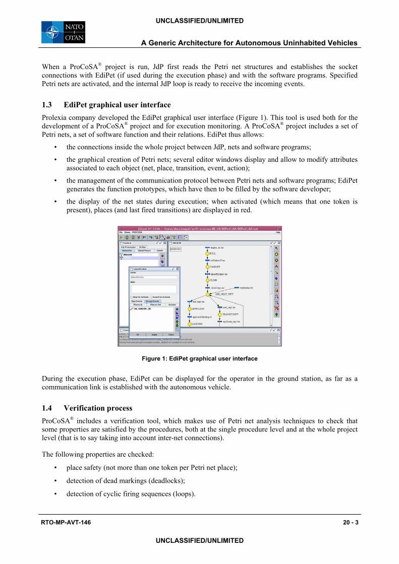
1.3 EdiPet graphical user interface Prolexia company developed the EdiPet graphical user interface (Figure 1). This tool is used both for the development of a ProCoSA® project and for execution monitoring. A ProCoSA® project includes a set of Petri nets, a set of software function and their relations. EdiPet thus allows:
• the connections inside the whole project between JdP, nets and software programs;
• the graphical creation of Petri nets; several editor windows display and allow to modify attributes associated to each object (net, place, transition, event, action);
• the management of the communication protocol between Petri nets and software programs; EdiPet generates the function prototypes, which have then to be filled by the software developer;
• the display of the net states during execution; when activated (which means that one token is present), places (and last fired transitions) are displayed in red.
Figure 1: EdiPet graphical user interface
During the execution phase, EdiPet can be displayed for the operator in the ground station, as far as a communication link is established with the autonomous vehicle.
1.4 Verification process ProCoSA® includes a verification tool, which makes use of Petri net analysis techniques to check that some properties are satisfied by the procedures, both at the single procedure level and at the whole project level (that is to say taking into account inter-net connections).
The following properties are checked:
• place safety (not more than one token per Petri net place);
• detection of dead markings (deadlocks);
• detection of cyclic firing sequences (loops).

A Generic Architecture for Autonomous Uninhabited Vehicles
20 - 4 RTO-MP-AVT-146
UNCLASSIFIED/UNLIMITED
UNCLASSIFIED/UNLIMITED
The principle of this analysis lies on the automatic generation of the reachability graph, which contains all the possible reachable states of each net and of the whole set of interconnected nets. As nets are safe, this set is necessarily finite, and its analysis permits to deduce the above properties.
2 TUTORIAL EXAMPLE The basic example that explains how to program an embedded decision architecture using ProCoSA® software package is a simple project for the supervision of an autonomous Uninhabited Aerial Vehicle (UAV). The different stages for architecture development are described in the following subsections. The vehicle is totally autonomous once the mission begins: there is no communication with an operator during mission execution.
2.1 Vehicle mission The objective of the UAV mission is to achieve survey operations while flying a sequence of legs: a leg can be a transit leg or a payload leg. Two payloads are available onboard (e.g. cameras). Each leg is defined by its starting waypoint, its ending waypoint, and by activated payloads for payload legs.
The nominal phases describing the flight plan are the following: mission preparation (plan storage), runway rolling, takeoff, climb to the cruise altitude, leg following, approach to the landing strip, and land.
Two types of disruptive events may affect the mission; a reaction is specified for each one:
• in case of an engine failure, transit to the nearest emergency site;
• in case of a payload failure, update of the sequence of waypoints and mission resuming.
2.2 Software program coding Embedded decision functions allow the vehicle to be autonomous. These functions are developed independently. This is also the case for the guidance function that computes vehicle moves and controls payloads. In this tutorial, two software programs are used:
• GUI software program simulates vehicle guidance and payload control;
• DEC software program stores all information relative to the mission and achieves decision tasks in case of non-nominal situations.
These software programs are simplified versions. In a real architecture, more sophisticated software programs have to be developed to enable to close the loop {perception, situation assessment, decision, and action}.
EdiPet interface is used to code ProCoSA® Petri nets; functions of GUI and DEC software programs, events they can send by return, and parameters associated to function’s calls and events were previously specified for the example project. Figure 3 illustrates an example of a software program call (the GUI_TakeOff function is activated by the GUI_ROLL_OK event at the end of the runway rolling phase) and an example of a return event (the DEC_LEG_next event is received after the call of the DEC_NextLeg function).
2.3 Nominal behaviour modelling The nominal behaviour for the vehicle is to follow the flight plan. With Petri nets, the natural way to implement such a nominal behaviour is to model each vehicle phase by a place and each phase change by a transition. A generic solution for leg following is to model a loop until the end of the sequence. DEC program knows the leg sequence and manages its update.

A Generic Architecture for Autonomous Uninhabited Vehicles
RTO-MP-AVT-146 20 - 5
UNCLASSIFIED/UNLIMITED
UNCLASSIFIED/UNLIMITED
Two Petri nets model then the nominal behaviour:
• the MISSION net manages phase sequencing;
• the PAYLOADS net manages payload activation and deactivation; as events relative to these controls are sent by DEC program, there is no direct relation between MISSION and PAYLOADS nets.
The EdiPet project is shown on Figure 2. The execution begins when the MISSION net receives the MISS_GO event from the JdP Petri net player. In a real context, this event may be sent by an operator through a specific interface.
Figure 2 - Nominal project includes JdP, MISSION and PAYLOADS nets and GUI and DEC programs. The EVENTS net refers to the non-nominal behaviour.
Petri nets are built following three steps:
• creation of net structure (places, transitions and arcs) with the EdiPet interface;
• definition of initial places (displayed with a token) and arguments;
• association of events and actions to transitions according to the templates of the software program functions; events and actions are displayed on EdiPet interface through the “/ae” label attached to transition names. Examples on Figure 3 show this interpretation for respectively “roll to takeoff”, and “climb to next leg” phase changes.

A Generic Architecture for Autonomous Uninhabited Vehicles
20 - 6 RTO-MP-AVT-146
UNCLASSIFIED/UNLIMITED
UNCLASSIFIED/UNLIMITED
action:DEC_NextLeg
event: DEC_LEG_next= Wpt3
event: GUI_ROLL_OK
action:GUI_TakeOff
Figure 3 - Examples of Petri net interpretation
Figure 4 shows MISSION and PAYLOADS nets. The fact that the payloads are modelled separately enables the operator to monitor the payload states during mission execution. At the beginning of the mission, payloads are off: places PL1_OFF and PL2_OFF are marked. The confirmation of the payload states change is required by the net from GUI software program before setting up the state to ON or OFF.
Figure 4 - MISSION and PAYLOADS nets
2.4 Analysis of the nominal behaviour The verification process in EdiPet is run for each elementary net of the example, then for the combined net which is built - for an analysis purpose only – by taking into account the direct connections between elementary nets:

A Generic Architecture for Autonomous Uninhabited Vehicles
RTO-MP-AVT-146 20 - 7
UNCLASSIFIED/UNLIMITED
UNCLASSIFIED/UNLIMITED
• MISSION net: all places are safe, the tree includes 11 nodes, 2 are duplicated nodes, there are no dead markings;
• PAYLOADS net: all places are safe, the tree includes 33 nodes, 17 are duplicated nodes; this is consistent with the combination of all possible states of the two payloads; there are no dead markings;
• the results are the same for the net built with MISSION and PAYLOADS nets as there are executed in parallel (no direct connection between the two nets, through events or net activation requests).
A second verification step is performed through simulation; the whole project can be run from the EdiPet interface. In the example, the following successive processes are thus activated:
• Petri net player log process: this report is useful to check the activity of the Petri net player;
• Petri net player input process: this window allows the developer to send Lisp controls, for example the emission of the MISS_GO event;
• GUI and DEC software programs: the associated windows display the results of function calls.
Once all processes are activated, the developer can launch the mission by sending the MISS_GO event through the Petri net player input process: he can check the evolution of markings on EdiPet nets and the outputs information from the software programs. The mission was fully executed with respect to the flight plan and to the payload activations and deactivations.
2.5 Non-nominal behaviour modelling Non-nominal behaviours are modelled through (1) a third Petri net, EVENTS, which includes the reaction to both types of disruptive event, and (2) an extension of the MISSION net.
When a failure event occurs, the appropriate reaction is modelled:
• in case of an engine failure, after the killing of MISSION net (ordered by the action associated to the engine_failure transition of the EVENTS net), the DEC program computes the nearest emergency site; the EVENTS net then supervises the transit to this emergency site, that is modelled as a leg follow;
• in case of a payload failure, after the killing of MISSION net (ordered by the action associated to the payload_failure transition of the EVENTS net), the DEC program computes another list of waypoints that do not use the faulty payload; to resume the mission, a new instantiation of the MISSION net is created and the “replanning2leg” transition is fired.
Figure 5 shows the two parts of EVENTS net and Figure 6 shows the new place and transition coded for mission resuming in MISSION net. The final project for this embedded architecture is given on Figure 2.

A Generic Architecture for Autonomous Uninhabited Vehicles
20 - 8 RTO-MP-AVT-146
UNCLASSIFIED/UNLIMITED
UNCLASSIFIED/UNLIMITED
Figure 5 - Non-nominal EVENTS net
Figure 6 – New part of MISSION net
2.6 Analysis of the whole project The same kind of analysis on the whole project including the non-nominal behaviours can be performed.
However, the formal analysis of the augmented MISSION net obviously shows that places are no more safe, due to the added REPLAN_WAIT initial place, although this cannot happen during execution, as the MISSION net is “killed” before its re-activation; this illustrates existing limitations in the verification functions implemented currently, and shows a way of improving them by taking into account the “kill” action when performing the global analysis on the combined net.
The checking process of the whole project was successfully achieved through simulation tests including the occurrence of disruptive events.
3 AUTONOMOUS UNDERWATER VEHICLE PROJECT
GESMA group from French armament procurement agency DGA has been working on autonomy projects for several years. One is devoted to the development of an autonomous system for the execution of missions in a partially known environment by an Autonomous Underwater Vehicle (AUV). A ProCoSA® based architecture was implemented for the autonomous execution of a mission defined by a set of mission areas where a survey procedure is performed. At the end of these operations, the vehicle joins the end area. The environment is defined by bathymetry, currents, forbidden areas and non-navigable water data.
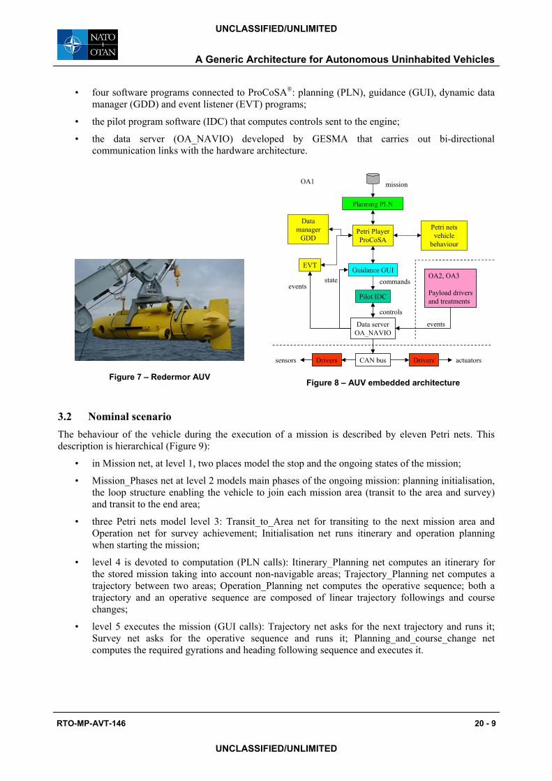
3.1 Experimental configuration and decision architecture overview Experiments are conducted with the Redermor AUV (Figure 7). Three computers and thirteen distributed Can interfaces with computation capabilities are installed on the platform. Serial link, Can Bus, I2C and Ethernet connections are available for payload integration and data exchange. OA1 computer is in charge of complex vehicle functions, supervision and mission planning; it thus includes the decision architecture (Figure 8). OA2 and OA3 computers are used for sonar payload controls and treatments like Computer Aided Detection and Classification algorithms for mine warfare.
For mission supervision, the decision architecture in OA1 computer includes:
• the Petri net player;
• vehicle behaviour modelling through Petri nets for nominal and non-nominal situations;
A Generic Architecture for Autonomous Uninhabited Vehicles
RTO-MP-AVT-146 20 - 9
UNCLASSIFIED/UNLIMITED
UNCLASSIFIED/UNLIMITED
• four software programs connected to ProCoSA®: planning (PLN), guidance (GUI), dynamic data manager (GDD) and event listener (EVT) programs;
• the pilot program software (IDC) that computes controls sent to the engine;
• the data server (OA_NAVIO) developed by GESMA that carries out bi-directional communication links with the hardware architecture.
Figure 7 – Redermor AUV
Pilot IDC
Planning PLN
Petri netsvehicle
behaviour
Petri PlayerProCoSA
Guidance GUIcommands
controls
Datamanager
GDD
state
mission
events
EVT
Data serverOA_NAVIO
OA2, OA3
Payload driversand treatments
events
CAN bus Drivers actuatorssensors Drivers
OA1
Figure 8 – AUV embedded architecture
3.2 Nominal scenario The behaviour of the vehicle during the execution of a mission is described by eleven Petri nets. This description is hierarchical (Figure 9):
• in Mission net, at level 1, two places model the stop and the ongoing states of the mission;
• Mission_Phases net at level 2 models main phases of the ongoing mission: planning initialisation, the loop structure enabling the vehicle to join each mission area (transit to the area and survey) and transit to the end area;
• three Petri nets model level 3: Transit_to_Area net for transiting to the next mission area and Operation net for survey achievement; Initialisation net runs itinerary and operation planning when starting the mission;
• level 4 is devoted to computation (PLN calls): Itinerary_Planning net computes an itinerary for the stored mission taking into account non-navigable areas; Trajectory_Planning net computes a trajectory between two areas; Operation_Planning net computes the operative sequence; both a trajectory and an operative sequence are composed of linear trajectory followings and course changes;
• level 5 executes the mission (GUI calls): Trajectory net asks for the next trajectory and runs it; Survey net asks for the operative sequence and runs it; Planning_and_course_change net computes the required gyrations and heading following sequence and executes it.

A Generic Architecture for Autonomous Uninhabited Vehicles
20 - 10 RTO-MP-AVT-146
UNCLASSIFIED/UNLIMITED
UNCLASSIFIED/UNLIMITED
TrajectoryTrajectory
Itineraryplanning
Itineraryplanning
Operationplanning
Operationplanning
Mission PhasesMission Phases
Transit to AreaTransit to Area
SurveySurvey
Planning and coursechange
Planning and coursechange
PLN
MissionMission
InitialisationInitialisation OperationOperation
PLN
PLN GUI
GUI GUI
Trajectoryplanning
TrajectoryplanningPLN
Software programsPLN: planningGUI: guidanceGDD: data manager
GDD GDD GDD
GDD GDD
Figure 9 – Hierarchy of Petri nets
3.3 Non-nominal scenario Many events that affect AUV missions require onboard replanning. At present, three types of events are implemented:
• an alarm event forces the vehicle to move directly to the end area: a new itinerary to avoid non-navigable areas and a new trajectory are computed then executed;
• when arriving on an objective area, if the real current is different from the predicted one it invalidates the already-computed survey: a new operative sequence is computed;
• the operator can ask for a local operation of inspection, for example to inspect a suspicious object. A specific operative sequence is planned before the vehicle resumes its mission.
These events are considered in the architecture through three new Petri nets. The Decision net implements the decisions that the vehicle must take according to the type of event, e.g. return to the end area in case of an alarm event. The Action net executes the decisions; it can run nominal nets. The Inspection net executes the inspection asked by the operator.
3.4 Lab bench tests and sea experiments A bench test has been developed to test the whole decision architecture. The OA_NAVIO data server has been connected on the one hand to a Redermor simulator, and on the other hand to an operator interface. The simulation of several missions allowed to validate the desired behaviour of the vehicle (Petri net modelling), the computation functions of PLN, the management of dynamic data in GDD, the guidance and the pilot of the vehicle (GDD and IDC) and the reception of disrupted events (EVT) together with the supervision on operator interface (Figure 10). Nominal and non-nominal scenarios were successfully simulated.
First sea experiments were conducted in Douarnenez Bay in March 2006. Three missions were carried out. The vehicle is tracked by acoustic means, and only a few points were available (Figure 11). Vehicle immersion, transit to the survey area, line following at a given altitude and return to the end area were successfully performed. Several autonomous behaviours were observed:
• the bathymetry of the mission area was different from predicted values: the vehicle adapted its manoeuvres to the measured altitudes;

A Generic Architecture for Autonomous Uninhabited Vehicles
RTO-MP-AVT-146 20 - 11
UNCLASSIFIED/UNLIMITED
UNCLASSIFIED/UNLIMITED
• predicted and real currents were different: when arriving in the survey area, a new operation sequence was computed with a new main direction for the survey;
• online computation of course changes allowed to take into account real currents.
These experiments validated the embedded use of ProCoSA®. Emphasis should now be put on guidance accuracy, perception function, classification of disruptive events, situation monitoring and assessment functions.
Figure 10 – Supervision of a simulated AUV mission. Survey area is blue, forbidden area is red, planning
trace is yellow, vehicle simulated trace is green.
Figure 11 – Supervision of a real AUV mission. Acoustic vehicle trace is green.
4 UNINHABITED AERIAL VEHICLE PROJECT
EADS and ONERA were involved in a national project [3] that aims at testing an architecture designed for mission supervision in a Uninhabited Aerial Vehicle (UAV) and demonstrating the relevance of such architectures in future uninhabited vehicles. As all categories of UAVs have to perform their missions in complex environments with the same types of constraints, the embedded architecture had to be generic, i.e. not dedicated to a given mission, environment or vehicle. As the mission may be disrupted by internal or external events, e.g. failures, weather situation, interfering aircraft, and threats, onboard plan monitoring and replanning were required in order to deal with nominal or disruptive events, avoid systematic return to base and proceed with the mission as well as possible given the new constraints.
The UAV mission consists in following an ordered set of payload and transit legs, as introduced in the tutorial example (section 4). In addition, once a payload has been followed, the operator has time to analyse the results and to ask the vehicle for a payload leg replay.
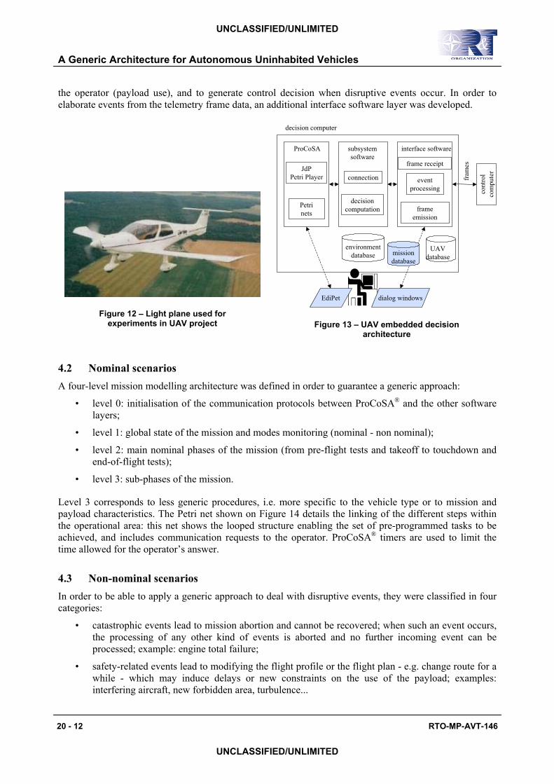
4.1 Experimental configuration and decision architecture overview Experiments were conducted on a light plane, a Dyn’Aero MCR-4S (Figure 12). Two computers are devoted to the control part of the plane, and a third one to the decision part, i.e. mission management. The first control computer is directly linked to the plane sensors and actuators (e.g. the automatic pilot) and to the ground station, while the second one acts as an interface between the previous real time control computer and the decision computer: it sends formatted frames and interprets elaborated orders.
The role of the software decision architecture implemented on the decision computer through ProCoSA®
(Figure 13) is thus to monitor the main mission phases of the nominal scenario, to manage the dialog with
A Generic Architecture for Autonomous Uninhabited Vehicles
20 - 12 RTO-MP-AVT-146
UNCLASSIFIED/UNLIMITED
UNCLASSIFIED/UNLIMITED
the operator (payload use), and to generate control decision when disruptive events occur. In order to elaborate events from the telemetry frame data, an additional interface software layer was developed.
Figure 12 – Light plane used for experiments in UAV project
environmentdatabase mission
database
UAVdatabase
Petrinets
JdPPetri Player
EdiPet
subsystemsoftware
connection
decisioncomputation
interface software
frame receipt
eventprocessing
frameemission
cont
rol
com
pute
r
fram
es
ProCoSA
decision computer
dialog windows
Figure 13 – UAV embedded decision architecture
4.2 Nominal scenarios A four-level mission modelling architecture was defined in order to guarantee a generic approach:
• level 0: initialisation of the communication protocols between ProCoSA® and the other software layers;
• level 1: global state of the mission and modes monitoring (nominal - non nominal);
• level 2: main nominal phases of the mission (from pre-flight tests and takeoff to touchdown and end-of-flight tests);
• level 3: sub-phases of the mission.
Level 3 corresponds to less generic procedures, i.e. more specific to the vehicle type or to mission and payload characteristics. The Petri net shown on Figure 14 details the linking of the different steps within the operational area: this net shows the looped structure enabling the set of pre-programmed tasks to be achieved, and includes communication requests to the operator. ProCoSA® timers are used to limit the time allowed for the operator’s answer.
4.3 Non-nominal scenarios In order to be able to apply a generic approach to deal with disruptive events, they were classified in four categories:
• catastrophic events lead to mission abortion and cannot be recovered; when such an event occurs, the processing of any other kind of events is aborted and no further incoming event can be processed; example: engine total failure;
• safety-related events lead to modifying the flight profile or the flight plan - e.g. change route for a while - which may induce delays or new constraints on the use of the payload; examples: interfering aircraft, new forbidden area, turbulence...

A Generic Architecture for Autonomous Uninhabited Vehicles
RTO-MP-AVT-146 20 - 13
UNCLASSIFIED/UNLIMITED
UNCLASSIFIED/UNLIMITED
• mission-related events only have consequences on the mission itself; replanning amounts to adapt the mission to the new constraints, e.g. remove waypoints; examples: camera failure, violated temporal constraint, new mission goal...
• communication-related events are related to communication breakdowns between the UAV and the ground; such events result in the UAV being fully “autonomous” therefore it has to proceed with the mission as planned; example: telemetry failure.
According to this classification, one Petri net was designed for each disruptive event category: an example is given by the engine failure Petri net shown on Figure 15: one can note the use of the “global places” feature (see section 1.1), which enables to adapt the reconfiguration actions to the current state of the mission. This reconfiguration process is achieved through software function activation requests, which enable to build a set of control orders to be sent to the control computer.
Figure 14 – Modelling of the linking of operational tasks
Figure 15 – Engine failure reaction modelling
4.4 Ground and flight tests Several series of field tests were realised in 2006. A test series was organised as a two-step process: during the first week, ground tests were conducted in order to prepare and simulate the scenarios to be run on the plane. Flight tests were conducted during the second week, with a pilot and an operator onboard the plane.
Seven scenarios were then tested, including single or multiple disruptive events occurrence: for example, the most complex one includes first a payload failure, then a simulated interfering aircraft, and finally a simulated engine failure.

A Generic Architecture for Autonomous Uninhabited Vehicles
20 - 14 RTO-MP-AVT-146
UNCLASSIFIED/UNLIMITED
UNCLASSIFIED/UNLIMITED
A double check process was achieved during each flight test. Flight data (telemetry frames) and the corresponding Petri net states was registered onboard. The ProCoSA® layer of the decision computer was duplicated on the ground station that also received the real-time telemetry frames, thus enabling system state to be monitored on the ground.
The following conclusions were drawn from these experiments: • vehicle behaviours modelled by Petri nets were correctly executed; • multiple disruptive events were dealt with without conflict; • the Man Machine Interface prototype used by the operator needs to be improved; • the real time hardware implementation of the system needs to be strengthened.
The following steps would consist in testing a direct connection between the decision computer and the autopilot and to enrich the replanning algorithms.
5 CONCLUSIONS AND PERSPECTIVES
The ProCoSA® software package is used by ONERA for controlling and monitoring highly autonomous systems. It allows fast prototyping of embedded decision architectures. Petri net procedures model the desired behaviours of the uninhabited vehicle, and the hierarchical modelling features enable to structure the whole application in a generic way: at the highest description level, generic behaviours can be described, regardless of the characteristics of a given vehicle; at the lowest level, they specify the sequences of elementary actions to be performed by the vehicle or the payloads. This formalism allows parallelism modelling and asynchronous event handling.
Industry and research develop their own architectures and no standard is emerging. This favours emulation but makes it difficult to compare different platforms. Several properties can be expected for such architectures: modularity (both at the design level and the ability to receive new components), easiness of implementation, easiness of interfacing, genericity, adaptivity, interoperability, extensibility, portability, maturity, ability to be validated…
The key features offered by ProCoSA® to develop generic decision architectures for autonomy are the following ones:
• the modularity of the architecture is obtained by considering separate software programs that are synchronised by the supervision function; the architecture can then include new programs easily;
• implementation: a graphical user interface is available to code Petri net behaviours and their interfacing with software programs; it can also be used to display states online;
• communication with hardware components, operators and other vehicles can be achieved through specific interfaces must be developed performing data exchange, i.e. for telemetry and control frames treatment;
• architectures are generic regarding to mission objectives, environment and vehicle characteristics which are stored in databases; several scenarios can then be tested with minor modifications; moreover, if an operator interface is available for mission preparation, the obtained scenario can be easily embedded;
• vehicle nominal and non-nominal behaviours can be incrementally developed. New behaviours can be added to an existing structure, e.g. for the implementation of reactions to new disruptive events;
• the software includes a verification tool, which makes use of Petri net analysis techniques to check that some properties are satisfied by the procedures.

A Generic Architecture for Autonomous Uninhabited Vehicles
RTO-MP-AVT-146 20 - 15
UNCLASSIFIED/UNLIMITED
UNCLASSIFIED/UNLIMITED
Experimental demonstrations were conducted in 2006 on two different autonomous vehicles: an AUV and a “habited UAV” (for security reasons). These demonstrations validated the embedded use of ProCoSA® software. During sea tests, there was no interaction between the AUV and the operator: once the mission was launched, the vehicle performed its missions fully autonomously. During flight tests, the operator was able to modify some parameters. By the end of 2007, the ProCoSA® based architecture should be adapted to a new AUV able to perform Rapid Environmental Assessment missions.
Several ways of research could lead to the improvement of ProCoSA® software package:
• extension of analysis features to take into account timers, net kills, software program outputs;
• specification of a generic articulation between the decision level of ProCoSA® and the reactive level;
• comparison with existing decision architectures implemented onboard autonomous vehicles: centralised architectures based on Artificial Intelligence (Blackboards, multi-agents architectures…), hierarchical architecture with more than three levels, hybrid architectures both reactive and deliberative…
References
[1] Murata, T. (1989). Petri nets: properties, analysis and applications. IEEE. 77 (4), pp. 541-580.
[2] F. Dabe, H. Ayreault, M. Barbier, S. Nicolas, Goal Driven Planning and Adaptivity for AUVs, UUST 05 Unmanned Untethered Submersible Technology, 21-24 August 2005, Durham, NH, USA.
[3] M. Barbier, J.F. Gabard, J.H. Llareus, C. Tessier, J. Caron, H. Fortrye, L. Gadeau, G. Peiller, Implementation and Flight Testing of an Onboard Architecture for Mission Supervision, 21st IUAVS International Unmanned Air Vehicle Systems Conference, April 3-5, 2006, Bristol, UK.

A Generic Architecture for Autonomous Uninhabited Vehicles
20 - 16 RTO-MP-AVT-146
UNCLASSIFIED/UNLIMITED
UNCLASSIFIED/UNLIMITED


![Ultrasonic Methods for Human Motion Detection · Ultrasonic Methods for Human Motion Detection 9 - 2 RTO-MP-SET-107 UNCLASSIFIED/UNLIMITED UNCLASSIFIED/UNLIMITED measurements [1],](https://img.dokumen.tips/doc/110x75/5ae21e557f8b9ad47c8cabad/ultrasonic-methods-for-human-motion-methods-for-human-motion-detection-9-2-rto-mp-set-107.jpg)