Embed Size (px)
Citation preview

Robert Steinberger-Wilckens, Arvin Mossadegh Pour
A Fuel Cell System for Railbus Application
HydRail ConferenceBirmingham, 3 & 4 July 2012

Slide 2RSt, July 2012
Hydrogen & Fuel Cells Doctoral Training Centre
The Hydrogen & Fuel Cell Research Centre&
Hydrogen production, storage & handling
PEFC & HT-PEFCSOFCSystems & Modelling

Slide 3RSt, July 2012
Introduction
• hydrogen storage on board vehicles remains sub-optimal• increase of storage pressure to 70 MPa to reduce size and/or
extend range• metal hydrides can offer an alternative – the tank is practically
pressure-less, H2 losses are low and handling simple• high weight of metal hydride tank itself and low adsorption
figures (~5% hydrogen) are a problem for mobile applications• new materials allow loading up to 14% but require high
temperatures in desorption process

Slide 4RSt, July 2012
The Project Idea
• combine high-performance metal hydride tank with SOFC system and use the exhaust heat for discharging the tank
• possible applications:- rail transport- marine vessels
• in both applications weight is of minor importance or even welcomed
• preferably (in first instance) aplication to Auxiliary Power Units for on-board electricity production
• test objects:- APU for diesel rail buses- APU for harbour vessels, service vessels, marine research vessels

Slide 5RSt, July 2012
Application Rail Bus
• diesel-driven vehicles
• travel medium distances in shuttle service
• i.e. hydrogen supply easily accomplished
• energy demand suitable for metal hydride tank
• environmental benefit through reduction of diesel exhaust gases in stations etc.
• possibility to extend functions from APU to diesel-electric drive or hybrid drive train
Slide 6RSt, July 2012
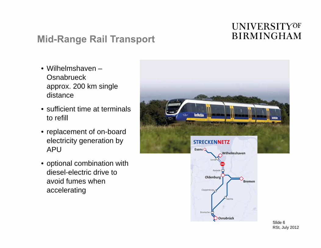
Mid-Range Rail Transport
• Wilhelmshaven –Osnabrueck approx. 200 km single distance
• sufficient time at terminals to refill
• replacement of on-board electricity generation by APU
• optional combination with diesel-electric drive to avoid fumes when accelerating

Slide 7RSt, July 2012
Travel Requirements
• re: Siemens Desiro
• total electric power on-baord: 15 kW
• SOFC system net efficiency 50%
• 75 kWh of hydrogen for 2 hours travel + ½ hour of stops
• 2,5 kg of H2

Slide 8RSt, July 2012
Solid Oxide Fuel Cell -Principle
characteristics:- 700 deg.C operating temperatureadvantages:- high electrical efficiency- high value heat- relatively insensitive to fuel impurities

Slide 9RSt, July 2012
G. Barkhordarian et al. (GKSS, EP1824780, Dec.2004, Deutschland 10 2004 061286.9)
MgB2 + 2 LiH + 4H2MgH2 + 2 LiBH4
MgB2 + CaH2 + 4H2MgH2 + Ca(BH4)2
MgB2 + 2 NaH + 4H2MgH2 + 2 NaBH4
Metal Hydride Concepts
Reactive Hydride Composite:
T ~ 350 °C – 400 °C
7.8 – 11.4 wt%
Sodium Alanate:
2 Na3AlH6 + 4 Al + 6 H26 NaH + 6 Al + 9 H2 6 NaAlH4
T ~ 125 °C
5.6 wt%

Slide 10RSt, July 2012
Volume 260 litre
(compact vehicle: 9 l petrol or 1.2 kg H2 for 100 km)
73 l
167 l
175 kg
H2-gas 700 barComposite shell
liquid H2
MgH2
Tank weight and volume for 500 km range (6 kg H2 = 200 kWh)m
etal hydrides
Storage Alternatives
NaAlH4
LiBH4 / MgH2
285 kg
92,9 l130 kg
Weight 133 kg
92 kg
167 l
Status: 22.1.2009
200 l462 kgHydralloy C®
(GKSS Tank f. SAX3)

Slide 11RSt, July 2012
Hydrogen Sorption of a Reactive Hydride Composite 2LiBH4+MgH2 2LiH+MgB2
loading, 350°C, 50 bar H2unloading, 400°C, 5 bar H2

Slide 12RSt, July 2012
Absorption Desorption
Metal Hydride Tanks (Sodium Alanate)

Slide 13RSt, July 2012
Internal Hull External Hull
Improvements with respect to the previous model:
Weight: 1,58 (up to 2.4 possible) instead of 0,865 wt. %; + 83 % ( up to +178 %) by light weight hull materials
Volumen: 31,2 instead of 21 kgH2/m3; + 49 % by compaction of the storage material
Metal Hydride Tanks (Sodium Alanate) (2)

Slide 14RSt, July 2012
AnodeMH Tank
Cathode
System Concept
400°C700°C
SOFC
heat
Aux. Hydrogen Tank
heat via burner
start up
H2
questions:- balance of heat flow - balance of gas flows- sizing of tank for applicationduring start up phase

Slide 15RSt, July 2012
AnodeMH Tank
Aux. Hydrogen Tank
Air
20ºC
λ=8
Cathode800ºC
+50 mbar
Air
800°C
27 m^3/h
Start Up Phase

Slide 16RSt, July 2012
Anode
MH Tank
Aux. Hydrogen Tank
Air
20ºC
λ=8
Cathode
600ºC
+50 mbar
700ºC
+30 mbar
Air
Operational Phase
400ºC, 5 bar

Slide 17RSt, July 2012
Stack and Tank Modelling
stack considered as heat exchanger during start-up
• zero-dimensional SOFC model during operation• no flow fields• no transient behaviour, apart from temperature dependance
tank is heated by air in the outer hull and releases H2when heated to core

Slide 18RSt, July 2012
Start-up of Metal Hydride Tank

Slide 19RSt, July 2012
Start-up of SOFC Stack

Slide 20RSt, July 2012
Conclusions and Outlook
• system can be started within one hour• heat flux and gas flows can be balanced• hydrogen release rate is in balance with stack fuel
requirements
• design needs further refinement - reduction of start-up time- proper temperature control
• further work to be done on - system transients- adaptatoin to application requirements

Slide 21RSt, July 2012
Thank you for your attention!
Acknowledgments go to:
IEK-PBZ – Fuel Cell Project at Forschungszentrum Juelich
Klaus Taube, Jose Bellosta von ColbeHelmholtz-Zentrum Geesthacht