Embed Size (px)
Citation preview
lable at ScienceDirect
Energy 118 (2017) 197e208
Contents lists avai
Energy
journal homepage: www.elsevier .com/locate/energy
A flexible control strategy of plug-in electric vehicles operating inseven modes for smoothing load power curves in smart grid
Siwar Khemakhem, Mouna Rekik, Lotfi Krichen*
National Engineering School of Sfax, Control and Energy Management Laboratory (CEMLab), BP 1173, 5052, Sfax, Tunisia
a r t i c l e i n f o
Article history:Received 15 August 2016Received in revised form30 November 2016Accepted 11 December 2016
Keywords:Plug-in electric vehiclesLithium-ion batterySmart gridSupervision strategyLoad power variance
* Corresponding author.E-mail address: [email protected] (L. Kriche
http://dx.doi.org/10.1016/j.energy.2016.12.0390360-5442/© 2016 Elsevier Ltd. All rights reserved.
a b s t r a c t
Plug-in electric vehicles (PEVs) seem to be an interesting new electrical load for improving the reliabilityof smart grid. The purpose of this work is to investigate a supervision strategy based on regulatedcharging of PEVs in order to guarantee an optimized power management of the system and consequentlya flatter power demand curve. The system mainly includes PEVs powered by a Lithium-ion batteryensuring the charging and discharging operations of these PEVs at home and a daily load powerdemanded by home appliances. The purpose of the considered strategy is to detect the connection statusof each PEV and to establish the priority order between these PEVs with certain flexibility which resultsin managing the PEVs through seven operating modes. The response of the control algorithm enables toensure the power flow exchange between the PEVs and the electrical grid, especially at rush hours, andto minimize load power variance aiming to achieve the smoothness for the power demand curve and toreduce the stress of the electrical grid. The simulation results are presented in order to illustrate theefficiency of this power control approach.
© 2016 Elsevier Ltd. All rights reserved.
1. Introduction
Up-to-date, the world has undergone a challenge in terms ofproviding electricity and ensuring global energy requirements. Thechallenge is mainly due to the shortage of primary energy resourcesfrom conventional fossil fuels like natural gas, coal and oil [1]. As aresult, there is a great tendency to integrate the renewable energyresources and the use of plug-in electric vehicles (PEVs) on thesmart grid in order to minimize reliance on conventional energyresources, satisfy the energy demands and consequently decreasingconcerns related to global warming effects as well as the onesrelated to energy crisis [2e5].
The excessive electricity consumption causes intense surges indemand during peak hour which can cause undesirable impactsand harm the stability of the existing network. That's why; someresearchers are working on ways to minimize load power varianceby using renewable energy sources. In Ref. [6], a stochastic multi-objective daily volt/var control based on hydro-turbine, fuel cell,wind turbine, and photovoltaic power plants are investigated. Astudy in Ref. [7] has developed a new control strategy that involves
n).
wind and photovoltaic generation subsystems. This strategy hasbeen suggested with the objective of load power demand satis-faction, storage and grid constraints verification in order to avoidblackout. These methods have presented good solutions to reduceload power variance and enhance power electrical system quality.However, the common disadvantage of this renewable distributedgeneration is their intermittent and unstable production due totheir dependence on weather change and climatic fluctuation.Currently, power systems supervision has been changing leading toaccomplish renewable energies gaps and use new paradigms in thefunctioning and improvement of power systems.
Plug-in Electric Vehicles (PEVs) as an emerging new electricalload and a significant approach on smart grid, have attracted moreattention worldwide and have appeared as future solution towardssolving problems for the energy management owing to theirmobility and power storage properties [8,9].
In that, smart grid as a suitable concept has a potential toimprove grid modernization for making it more able to addressfuture need, more efficient and accommodating [10]. Some re-searchers are interesting in smart meters, electricity storage tech-nologies, and electrical local smart grids in which they develop thedesign of coherent smart energy systems as an integrated part ofachieving future 100% renewable energy and transport solutions[11,12]. Ref. [13] has presented the interest profits, risks and a

S. Khemakhem et al. / Energy 118 (2017) 197e208198
challenge concerned in smart grid and has insisted on the impact ofthe actual smart grid modernization for potential and reliable en-ergy generation. Indeed, the need for new flexible electric powerwith quality improvement leads to the development of the bi-directional flow of electricity and information [14]. Communica-tions flow is used to collect data supplied by meters and sensorsthat can be used to permit both consumers and utilities to reply tothe grid status [15]. In this context, these PEVs are equipped bybatteries which can operate as a load on the grid known as grid-to-vehicle (G2V) concept or as a power source known as vehicle-to-grid (V2G) concept [16,17]. It has been proved that the V2G tech-nology can describe an interactive relationship between PEVs andthe power grid [18,19], help to realize the balance between pro-duction and consumption of power grid, participate in frequencyregulation [20], so as to flatten the variation of the load powerprofiles [21], reduce cost [22] and integrate renewable energysources [23]. From these interesting benefits, various researcheshave been carried out the PEVs and their integration into the grid.Ref. [24] discusses the impact of PEVs and V2G technology tointegrate a highly level of wind generation without excess onelectricity production as well as greatly to minimize national CO2emissions. Ref. [25] describes the main challenge of renewableenergy strategies to include the transportation field in these stra-tegies for sustainable development purpose and discusses the po-tential solutions for this challenge in Denmark case. Authors inRef. [26] have concentrated on the notions of G2V concept and V2Gtechnology, their economic benefits depending on the chargingstrategies of PEVs (coordinated/uncoordinated charging) and theireffects on power distribution networks. Others in Ref. [27] areworking on the optimal scheduling of charging/dischargingbehavior of electrics vehicles. They are adjusting the PEVs powerand are proposing a locally optimal scheduling scheme.
Researchers in Ref. [28] are working on the performance ofbatteries for PEVs. They have exanimate the recent battery tech-nologies for PEV and the most important parameters to maximizethe effectiveness and competitiveness of PEV battery on short andlong term. Ref. [29] has presented an estimated sample model-based health management of Lithium-ion batteries for electrifiedvehicles to maintain the battery lifecycle. A study in Ref. [30] hasexplained new dynamic model at battery swapping station forelectric vehicles in electricity market.
Within the smart grid concept, much studies has beenconcentrated on the active participation of demand-side response,household electricity use and smart homes in terms of theirstructures, components, and benefits [31e33]. An overview ofservices offered by smart home and reveals key barriers to smarthome adoption was carried out in Ref. [34]. Authors in Ref. [35]focus on the prediction of the next day energy consumption forsmart homes. Others in Ref. [36] proposed a home energy man-agement system to manage household energy consumption aimingto keep the customer comfort at a good condition. Moreover, thereare several studies aiming to reduce load power variance. Forinstance, an energy retailer scheme that permits investigating de-mand response in electricity supply is presented in Ref. [37] inorder to achieve load minimizing based on price elasticity usingPower Systems Computer Aided Design (PSCAD). An improvementof the load variance in household smart micro-grid using chargingprofiles of plug-in hybrid electric vehicles driven by the residentswas explored in Ref. [38].
Although these considered studies have elaborated differentaspects for PEVs charge scheduling, energy loss minimization andconsequently load power variance enhancing, however, it is notablethat there is not enough flexibility either in PEV time connection, orin energy demand as well in duration of charging.
In this paper, a flexible control strategy of PEV operating in
seven modes is proposed. The aim is to satisfy the energy dis-patching between PEVs and power grid and to minimize the loadpower variance. For that, an appropriate algorithm must be ach-ieved to generate the optimal required powers and avoid the highelectricity demand in peak hours. In fact, the main contribution ofthis work is tomonitor the system under different operationmodesof activation according to the following constraints: (i) the dailyload demand of the household appliances, (ii) the connection timeof the each PEV, (iii) the priority order and the state of charge (SOC)value of each battery.
The algorithm presented is flexible and applicable for any houseequipped with two PEVs which could provide grid support by in-jection or absorption of their optimal reference powers whencharging slot time that are available at home.
The flexibility of this approach is shown in PEV time connectionand their charge/discharge duration. Indeed, the bidirectional en-ergy flow of vehicle to home (V2H) provides greater flexibility tocontrol the PEV battery energy which is one of the recent tech-nologies. It can be considered not only as an electric load but also asa storage system and thus a supplier of electrical demand at homeappliances. The focus of this considered strategy is thus, firstly, thedetection of the presence of each PEV taking into account the pri-ority selection of PEV owner chosen charging time period, andsecondly, the availability of these PEVs to switch between manypower flow feasibilities according to seven operating modes with aflexibility degree in order to achieve a flatter daily power demandcurve.
The paper is structured as follows: section 2 shows thedescription of the studied system and the modeling of the batteryas an important electrical part in exchanging power for each PEV.Section 3 details the control of PEV power generation. In section 4,the power control algorithm applied to the studied PEVs taking intoaccount their connection status to the grid will be described. Aflexible strategy is investigated to show the impact of this regulatedcharging on minimizing load power variance and flatteningconsequently the daily power demand curve. The simulation re-sults and the conclusion of this work are developed in sections 5and 6, respectively.
2. System description and modeling
2.1. System description
The aim of this paper is to point out the high power of PEVswhich could provide significant flexibility in their connection timeand duration of charging when they are parked at home and todemonstrate the appropriate merits of V2G technology. As shownin Fig. 1, the studied home is equipped by AC powered devices, DCpowered devices associated to DC/AC power converters to connectthese load to the AC power grid and PEVs with their bidirectionalchargers.
Each PEV includes a Li-ion battery pack, an inductive filter L, abidirectional DC/DC converter, a DC link voltage bus, a bidirectionalDC/AC converter and a line which is represented as an RL filter.
The direction of the current is the criterion to define the chargeor discharge phase of the battery. Positive battery current de-termines the discharging operation and negative battery currentdetermine the charging process. The L filter participates into thechopper operation and smoothes the charge and discharge currentripples. This inductor filter and the buck-boost DC/DC converter areused to ensure the possibility of bidirectional power flow exchange(charge/discharge) and to adjust the voltage levels between thebattery pack and the DC bus. Therefore, the DC/DC converter aimsto adapt the battery output voltage to the appropriate inverterinput voltage. The bidirectional DC/AC converter which is

Fig. 1. Scheme of home components.
S. Khemakhem et al. / Energy 118 (2017) 197e208 199
interposed between the DC bus and the line achieves the energytransit from the DC bus to the appropriate AC values in order toinject (or absorb) sinusoidal currents into the electrical grid [39].This converter acts as a rectifier in chargingmode and as an inverterin discharging mode. The RL filter is used to improve the quality ofcurrent injected or absorbed to the grid, to attenuate harmonicscaused by the DC/AC converter and guarantee a three-phase voltagesource to attain a quasi sinusoidal voltage. The integration of bothcommunication and electrical power flows is the essential charac-teristic of smart grid. The modern technologies in the smartmetering are essential to ensure a successful integration of PEVsframework V2G concept, a dynamic PEV load as well as effectiveinformation measured of the power demanded or supplied to grid[40]. For that, it is assumed in this paper that each PEV have twoflows when it is plugged-in. In addition, a “flexible supervisionstrategy of PEVs powers” is proposed to switch between differentoperating modes, to ensure the dispatch of power between PEVsand smart grid in a flexible way depending on the informationobtained by the smart meter, so as to reduce the load power vari-ance and highly achieve the efficiency of the load power curve. Thisstrategy is applicable in any home in which the base load of thehousehold appliances is defined from the typical daily load profile.
2.2. Modeling of the battery
The PEV modeling will gain importance in the electric part. Thebattery has an important effect on the V2G systems. This electricalcomponent assumes the power exchange between the PEV and the
power grid. The battery model in this study, as it is considered asthe most recent battery technology used in PEVs, is based on acommercially lithium-ion (Li-ion). Lithium-ion battery wasselected in this work because the cell battery has a significant en-ergy densities, high specific power, long lifetime, lightweight na-ture, security, lower cost, lower waste of charge, and, potentiallyhigher voltage [41e43]. The simplest form of the “electrical batterymodel” is a voltage source connected in series with an internalresistance. It can be distinguished that there is a characteristicequation of the battery voltage, for each operating mode.
The voltage source is modeled by the charge equation oflithium-ion battery as follows [44]:
Vbatt ¼ U0 � R$i� KQ
i$t � 0$1Qi* � K
QQ � i$t
i$t þ Ae�B$i$t (1)
In discharging mode, the equation of the voltage source oflithium-ion battery is described as [44]:
Vbatt ¼ U0 � R$i� KQ
Q � i$ti* � K
QQ � i$t
i$t þ Ae�B$i$t (2)
The state of charge (SOC) equation is based on coulomb count-ing method. This method is simple to implement but the initial SOCvalue should be known. The equation is written as follows [45]:
SOC ¼ 100�1� i$t
Q
�(3)
In order to accomplish the demand of total voltage and current

S. Khemakhem et al. / Energy 118 (2017) 197e208200
levels, many Li-ion battery cells are connected in series and/orparallel configurations. The association of battery cell in series andparallel determines a battery pack.
The series number cell of a battery pack NS is calculated as [46]:
NS ¼UDC
U0(4)
The number of parallel cells of battery packs NP is expressed as[46]:
NP ¼ EbatðEcell � DE�w$wcellÞ$NS
(5)
With:
DE�w ¼ a$1;4 (6)
The parameters of the studied PEVs battery cell are detailed inthe Appendix.
The SOC of the studied batteries should be maintained in anoperating range of limits in order to avoid the over-charge and the
Fig. 2. Control configuration of each PE
deep discharge of the battery:
SOCmin � SOC � SOCmax (7)
With:SOCmin ¼ 0;2; SOCmax ¼ 0;8:The SOC depends on the distance run by each PEV. The
demanded energy for traveling Ptr depends on the distance run ADand the vehicle efficiency mPEV as given in Ref. [47]:
Ptr ¼ mPEV$AD (8)
3. Control of PEV power generation
The control of each PEV power generation is achieved by thecontrol of the different power converters. This control, summarizedin Fig. 2, is classified into three parts. The first one illustrates thecontrol the DC/DC converter and the battery current.
-Current control: A PI regulator is used to adapt the batterycharge or discharge current to the reference value
00Ibat�ref
00. While
the positive battery current corresponds to a discharge phase, the
V structure for power generation.

S. Khemakhem et al. / Energy 118 (2017) 197e208 201
negative battery current corresponds to a charge phase. This PIregulator is expressed by the following equation:
Um�bat ¼ Ubat � PI�Ibat�ref � Ibat
�(9)
-Converter control: The main role of DC/DC converter is to adaptthe battery output voltage to the adequate inverter input voltage.The control of the DC/DC converter is given by the duty ratio asfollow:
mbat�ref ¼Um�bat
UDC(10)
The second part corresponds to the DC bus control. A PI regu-lator is used to control the DC bus voltage by setting the referencecurrent
00Ibat�ref
00. Then, the reference of the battery exchanged
power00Pbat�ref
00can be calculated taking into account the needed
power to control the DC bus voltage00PDC�ref
00and the power to
satisfy demands00PD
00, as given by the following equation.
Pbat�ref ¼ PDC�ref � PD (11)
Indeed, the DC bus control depends mainly on the proposedstrategy which consists in controlling the battery state and calcu-lating its needed reference power to be absorbed or supplied.
The third part which is depicted in Fig. 2 presents the DC/ACconverter control and currents control Indeed, the bidirectional DC/AC converter ensures the control of the continuous voltage in gridside as well as the exchange of active and reactive powers betweenthe PEVs and the grid. The injected or the absorbed currents areregulated according to the different operating modes of the pro-posed algorithm. This algorithm is developed to monitor the powerflows between each PEV and the power grid in order to make de-cision to choose correctly the optimal references PEV powersPPEV1;2�ref and to ensure a flatter daily load power curve.The reac-tive power Qref is set to zero to ensure a power factor equals to one.These reference powers yield the components park referencecurrents
00itd�ref ; itq�ref
00for active and reactive powers management
goal. From the continuous voltage measurement and the modu-lated voltages, the operating of this converter is assisted by thecomputation of the reference phase voltages
00Vmd�reg ;Vmq�reg
00ac-
cording the following equations:
Vmd�reg ¼ 2UDC
Vmd (12)
Vmq�reg ¼ 2UDC
Vmq (13)
These voltages are used to generate the duty cycles of theinverter control signals. In order to regulate the line-to-line volt-ages, attenuate the generated harmonics and realize good perfor-mances in tracking, two PI correctors are used to control theconnection line. This control permits, simultaneously the three-phase voltage at the nominal frequency 50 Hz. The active andreactive powers transmitted into the grid through the line arecalculated as follows:
PGrid ¼ VGd itd þ VGq itq (14)
QGrid ¼ VGq itd � VGd itq (15)
4. Proposed control strategy
In order to achieve an optimal flow of PEVs powers in smart gridtransaction, a power control strategy is investigated. The consid-ered approach is applied for any house equipped with two PEVs.This strategy, depicted in Fig. 3, permits power dispatching be-tween these two PEVs and power grid and aims to minimize theload power variance. Seven operating modes are considered tocalculate the optimal reference powers of the two PEVs
00Pref�PEV1;2
00
absorbed or injected to the grid in case of lack or excess in loaddemand, respectively. The proposed algorithm which is built on“flexible supervision strategy of PEVs powers” as well as moni-toring the system correctly into seven operating modes is estab-lished to ensure the following roles:
� Receiving the daily load configuration data that describe thestudied household appliances, the connection state of the twoPEVs and the SOC of each battery.
� Establishing the priority order between these two PEVs withcertain flexibility.
� Assuring the powermanagement between the PEVs and loads inorder to reduce the stress of the electrical grid and achieve thesmoothness for the power demand curve.
� Controlling the batteries SOC and consequently avoiding thedeep discharge and overcharge of the batteries.
There are several conditions which are essential to ensure thefunctioning of the algorithm suggested above. First, the properconnection status of each PEV in which a specific PEV plugs-in atthe first of sometime-period and plugs-out at another time-periodmust be ensured. Second, it is essential to maintain the initial valueof SOC of each considered PEV battery. Indeed, equation (7) dem-onstrates the allowed minimum and maximum battery SOC of thestudied PEVs which need to be sustained within the allowablelevels to save the battery from deterioration and reduce batterydegradation. Finally, the total load power
00PL
00presented by daily
load profile and the reference average power of the studiedhome
00PR
00are to be well maintained. It is assumed that the average
reference power consists on the average household load power andthe average required power for the distance run by each PEV asexpressed in equation (16).
PR ¼ 1T
XTt¼1
ðPL þ PPEV1 þ PPEV2Þ (16)
The control is done by calculating the amount of PEVs powersneeded to be absorbed or injected into the power grid
00Pdiff
00by the
considered equation:
Pdiff ¼ PL � PR (17)
At each instant, the number, the connection time, the priorityorder of the considered PEVs and the sign of
00Pdiff
00are identified at
the same time.
� When there is an excess of load demand "Pdiff � 000. In this sit-
uation,00Pdiff
00should be injected into the grid from the PEVs.
Moreover, if the battery SOC value of the PEV is equal or lessthan the SOCmin: the PEV must be connected and waits forcharging. Else, if the battery SOC value is more than the SOCmin,then it is the V2G operation case. Indeed, the PEV acts todecrease the excess required energy and feedback the storedpower into the grid.
� When there is a lack of power consummation00Pdiff <0
00. In this
situation,00Pdiff
00should be absorbed from the grid. If the battery

Fig. 3. Flexible supervision strategy of PEVs powers.
S. Khemakhem et al. / Energy 118 (2017) 197e208202

Fig. 4. Total load power without PEV connection.
S. Khemakhem et al. / Energy 118 (2017) 197e208 203
SOC value of the PEV is equal or more than the SOCmax: the PEVis charged and it is ready for being used. Else, if the battery SOCvalue is less than the SOCmax; then it is the G2V operation. Infact, the PEV operates to compensate this lack and absorb theelectric power from the grid.
This algorithm receives, first, the total load power00PL
00, the
reference average power00PR
00, the connection status of PEV number
one00CSPEV1
00, the connection status of PEV number two
00CSPEV2
00, the
connection time of PEV number one00Tc1
00, the connection time of
PEV number two00Tc2
00, the battery SOC value of PEV number one
00SOCPEV1
00and the battery SOC value of PEV number two
00SOCPEV2
00,
as inputs, then, it is managed into seven operating modes:
4.1. Mode 1
This mode shows that no PEVs are connected to the grid. In thiscase: the number of PEVs is equal to zero and the total PEVs poweris also equal to zero
00PPEVt ¼ 0
00because there is no power trans-
mitted to the grid.
4.2. Mode 2
This is the mode where one PEV is at home and is available tojoin V2G or G2V operation. In this mode: the number of PEVsdetected is
00N ¼ 1
00which means that the connection status of PEV
number one is equal to one or connection status of PEV number twois equal to one.
00CSPEV1 ¼ 1 or CSPEV2 ¼ 1
00:
The first case of mode 2 (mode 2.1) is obtained when00Pdiff
00is
negative and the SOC of the connected vehicle00SOCcv
00is less than
the SOCmax , thus the PEV operates to compensate the lack of energyand absorb this quantity of power from the grid.
The second case of mode 2 (mode 2.2) is detected when00Pdiff
00is
positive and the SOC of the connected vehicle00SOCcv
00is more than
the SOCmin , so there is an excess of demand and the power quantityneeded
00Pdiff
00should be injected to the grid through this PEV.
According to these two cases: the power of PEV, when it is notconnected, is equal to zero
00PPEVNC ¼ 0
00and the total PEVs power is
equal to00Pdiff
00which is equal also to the power of connected
vehicle00PPEVt ¼ PPEVC
00.
4.3. Mode 3
It corresponds also to the availability of onePEV
00N ¼ 1
00and
00CSPEV1 ¼ 1 or CSPEV2 ¼ 1
00, but the connected
vehicle expects the minimum or the maximum SOC. This mode isobtained by two cases:
If00Pdiff
00is negative and
00SOCcv
00is equal or more than the SOCmax,
thus the PEV is totally charged and ready for being used. It is in thefirst case of mode 3 (mode 3.1) where the battery attends itsmaximum
00SOCcv ¼ SOCmax
00.
If00Pdiff
00is positive and
00SOCcv
00is equal or less than the SOCmin;
thus the connected PEV must wait for charging because its batteryexpects its
00SOCmin
00. It is the second case of mode 3 (mode 3.2).
The two cases stated above indicate that the00PPEVNC ¼ 0
00and
the total PEVs power is equal to the power of connected vehiclewhich is equal to zero
00PPEVt ¼ PPEVC
00.
The following modes 4, 5, 6 and 7 will appear when there aretwo PEVs
00N ¼ 2
00;
00CSPEV1 ¼ 1 and CSPEV2 ¼ 1
00. In this situation,
we have:
4.4. Mode 4
This mode is obtained by the activation of one of these twocases:
When00Pdiff
00is positive, the SOC of priority vehicle
00SOCpv
00is
more than the SOCmin and the SOC of secondary vehicle00SOCsv
00is
more than the SOCmin , this is the first case of mode 4 (mode 4.1)which is responsible for the discharging of the priority and thesecondary PEVs and feed backing power to the grid.
When00Pdiff
00is negative, the
00SOCpv
00is less than the SOCmax and
the00SOCsv
00is less than the SOCmax, which is the second case of this
mode (mode 4.2). This case is responsible for charging the priorityand the secondary PEVs.
Considering the two cases mentioned above, the total PEVspower is calculated from the power of the priority PEV and thepower of the secondary PEV which is equal to:00PPEVt ¼ PPEVP þ PPEVS
00.
4.5. Mode 5
There are, in this mode, two selected cases:If
00Pdiff
00is positive, the
00SOCpv
00is equal or less than the SOCmin
and the00SOCsv
00is equal or less than the SOCmin , the first case of
mode 5 (mode 5.1) is obtained. It is the case in which the batteriesof priority and secondary PEV reach their minimum SOC value.Hence, these two PEVs should be connected and wait for charging.
If00Pdiff
00is negative, the
00SOCpv
00is equal or more than the SOCmax
and the00SOCsv
00is equal or more than the SOCmax ,the second case of
mode 5 (mode 5.2) shows that the priority and secondary PEVs arecompletely charged and ready for being used because the batteriesSOC value attain their maximum value
00SOCmax
00.
These two cases demonstrate that there is no power exchangedwith the grid. Indeed, the power of the priority PEV is equal to zero00PPEVP ¼ 0
00; the power of the secondary PEV is equal to zero
00PPEVS ¼ 0
00and the total PEVs power is equal
to:00PPEVt ¼ PPEVP þ PPEVS
00.
4.6. Mode 6
In this mode, there are two interactive cases to distinguish:When
00Pdiff
00is positive, the
00SOCpv
00is more than the SOCmin and
the00SOCsv
00is equal or less than the SOCmin, which is the first case of
this mode (mode 6.1). The priority PEV is in discharging phasewhich can inject the stored power to the grid and consequentlyminimize load power variance, whereas, the secondary PEV attendsits
00SOCmin
00and must wait for charging.
When00Pdiff
00is negative, the
00SOCpv
00is less than the SOCmax and
the00SOCsv
00is equal or more than the SOCmax, which is the second
case of this mode (mode 6.2). The priority PEV is in charging phase
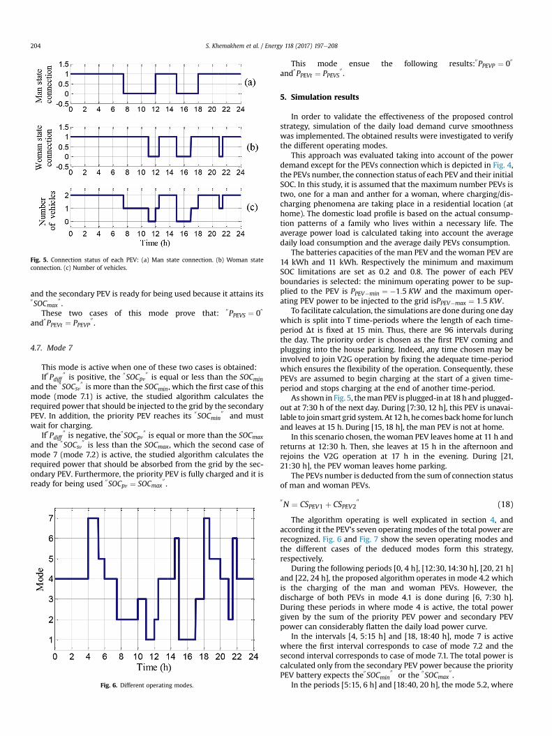
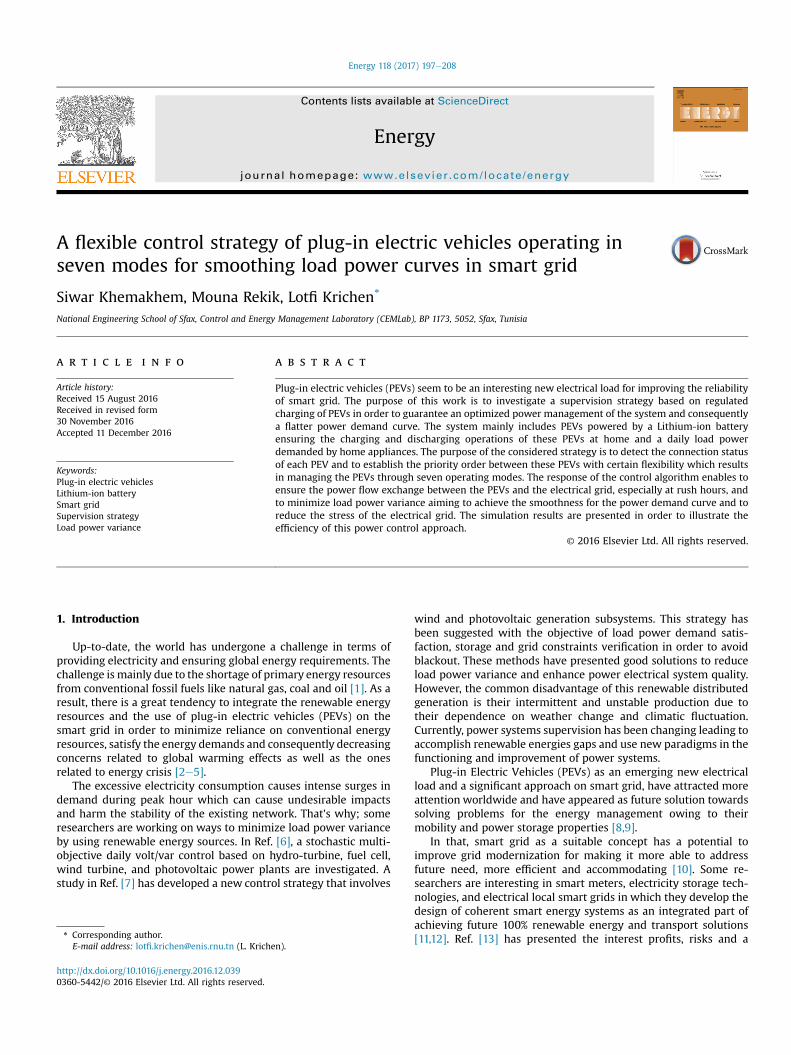
Fig. 5. Connection status of each PEV: (a) Man state connection. (b) Woman stateconnection. (c) Number of vehicles.
S. Khemakhem et al. / Energy 118 (2017) 197e208204
and the secondary PEV is ready for being used because it attains its00SOCmax
00.
These two cases of this mode prove that:00PPEVS ¼ 0
00
and00PPEVt ¼ PPEVP
00.
4.7. Mode 7
This mode is active when one of these two cases is obtained:If
00Pdiff
00is positive, the
00SOCpv
00is equal or less than the SOCmin
and the00SOCsv
00is more than the SOCmin, which the first case of this
mode (mode 7.1) is active, the studied algorithm calculates therequired power that should be injected to the grid by the secondaryPEV. In addition, the priority PEV reaches its
00SOCmin
00and must
wait for charging.If
00Pdiff
00is negative, the
00SOCpv
00is equal or more than the SOCmax
and the00SOCsv
00is less than the SOCmax, which the second case of
mode 7 (mode 7.2) is active, the studied algorithm calculates therequired power that should be absorbed from the grid by the sec-ondary PEV. Furthermore, the priority PEV is fully charged and it isready for being used
00SOCpv ¼ SOCmax
00.
Fig. 6. Different operating modes.
This mode ensue the following results:00PPEVP ¼ 0
00
and00PPEVt ¼ PPEVS
00.
5. Simulation results
In order to validate the effectiveness of the proposed controlstrategy, simulation of the daily load demand curve smoothnesswas implemented. The obtained results were investigated to verifythe different operating modes.
This approach was evaluated taking into account of the powerdemand except for the PEVs connection which is depicted in Fig. 4,the PEVs number, the connection status of each PEV and their initialSOC. In this study, it is assumed that the maximum number PEVs istwo, one for a man and anther for a woman, where charging/dis-charging phenomena are taking place in a residential location (athome). The domestic load profile is based on the actual consump-tion patterns of a family who lives within a necessary life. Theaverage power load is calculated taking into account the averagedaily load consumption and the average daily PEVs consumption.
The batteries capacities of the man PEV and the woman PEV are14 kWh and 11 kWh. Respectively the minimum and maximumSOC limitations are set as 0.2 and 0.8. The power of each PEVboundaries is selected: the minimum operating power to be sup-plied to the PEV is PPEV�min ¼ �1:5 KW and the maximum oper-ating PEV power to be injected to the grid isPPEV�max ¼ 1:5 KW .
To facilitate calculation, the simulations are done during one daywhich is split into T time-periods where the length of each time-period Dt is fixed at 15 min. Thus, there are 96 intervals duringthe day. The priority order is chosen as the first PEV coming andplugging into the house parking. Indeed, any time chosen may beinvolved to join V2G operation by fixing the adequate time-periodwhich ensures the flexibility of the operation. Consequently, thesePEVs are assumed to begin charging at the start of a given time-period and stops charging at the end of another time-period.
As shown in Fig. 5, themanPEV is plugged-in at 18 h and plugged-out at 7:30 h of the next day. During [7:30, 12 h], this PEV is unavai-lable to join smart grid system. At 12 h, he comesback home for lunchand leaves at 15 h. During [15, 18 h], the man PEV is not at home.
In this scenario chosen, the woman PEV leaves home at 11 h andreturns at 12:30 h. Then, she leaves at 15 h in the afternoon andrejoins the V2G operation at 17 h in the evening. During [21,21:30 h], the PEV woman leaves home parking.
The PEVs number is deducted from the sum of connection statusof man and woman PEVs.
00N ¼ CSPEV1 þ CSPEV2
00(18)
The algorithm operating is well explicated in section 4, andaccording it the PEV's seven operating modes of the total power arerecognized. Fig. 6 and Fig. 7 show the seven operating modes andthe different cases of the deduced modes form this strategy,respectively.
During the following periods [0, 4 h], [12:30, 14:30 h], [20, 21 h]and [22, 24 h], the proposed algorithm operates in mode 4.2 whichis the charging of the man and woman PEVs. However, thedischarge of both PEVs in mode 4.1 is done during [6, 7:30 h].During these periods in where mode 4 is active, the total powergiven by the sum of the priority PEV power and secondary PEVpower can considerably flatten the daily load power curve.
In the intervals [4, 5:15 h] and [18, 18:40 h], mode 7 is activewhere the first interval corresponds to case of mode 7.2 and thesecond interval corresponds to case of mode 7.1. The total power iscalculated only from the secondary PEV power because the priorityPEV battery expects the
00SOCmin
00or the
00SOCmax
00.
In the periods [5:15, 6 h] and [18:40, 20 h], the mode 5.2, where

Fig. 8. Charging profile of man PEV.
Fig. 9. Charging profile of woman PEV.
Fig. 7. Different interactive cases of the deduced modes.
S. Khemakhem et al. / Energy 118 (2017) 197e208 205
priority and secondary PEVs are totally charged and reached the00SOCmax
00, and mode 5.1, where priority and secondary PEVs reach
the00SOCmin
00, are respectively detected. During these periods,
mode 5 is observed in which no PEVs powers are exchanged and,
consequently, the total PEVs power calculated from the sum of thepriority PEV power and secondary PEV power is equal to zero.
In the intervals [7:30, 10 h], [12, 12:30 h] and [21, 21:30 h], mode2 is obtained where the total power is calculated from only the PEVconnected to home parking. Indeed, during [7:30, 8:30 h] and [21,21:30 h], mode 2.2 is active. The first period corresponds to womanPEV injection power; however, the second period corresponds toman PEV injection power. During [8:30, 10 h] and [12, 12:30 h],mode 2.1 is obtained. In the first interval, woman PEV absorbspower from the grid. Whereas, man PEV absorbs power from thegrid in the second interval.
In the periods [10, 11 h] and [17, 18 h], the total power deter-mined by the woman PEV power is equal to zero because the bat-tery attained its "SOCmax" in the first interval corresponding tomode 3.1 and it reaches its
00SOCmin
00in the second interval corre-
sponding to mode 3.2. During these two periods, mode 3 is active.In the time [11, 12 h], mode 1 is observed in which no PEVs are
detected and, consequently, the total PEVs power is equal to zerowhich is the same result in the following interval [15, 17 h].
During [14:30, 15 h] and [21:30, 22 h], mode 6 is functional inwhich the total power is given only by the priority PEV power (manPEV). In fact, the woman PEV (secondary PEV) expects its
00SOCmax
00
in the period [14:30, 15 h] corresponding to case 2 of mode 6.Whereas, it reaches its
00SOCmin
00during [21:30, 22 h] corresponding
to case 1 of mode 6.Fig. 8 and Fig. 9 illustrate the charging profiles of man PEV and

Fig. 12. State of charge curve of man PEV.
S. Khemakhem et al. / Energy 118 (2017) 197e208206
woman PEV during one day cycle. They show that the negativepowers correspond to charging cases where both PEVs consumethe difference power between the daily power requirement and thereference average power
00Pdiff
00. Whereas, the positive powers
correspond to discharging cases where PEVs feedback the storedpower to the grid.
From the power profile of man PEV, it is observable that, during[7.30, 12 h] and [15, 18 h], the man PEV does not absorb or supplyelectrical power because it is not connected from the grid. As far as,in the following intervals [11, 12 h], [15, 17 h] and [21, 21:30 h], thewoman PEV is not at home and, consequently it does not join theV2G system.
Both man and woman battery current curves are shown inFig. 10 and Fig. 11, respectively. These results confirm the chosenconvention in which negative currents are dedicated for chargingcases and positive currents for discharging cases.
The charging/discharging operation can be also confirmed bythe evolution of battery SOC curve in time as presented in Fig. 12and Fig. 13. As it seen, both man PEV and woman PEV have a spe-cific SOC curve for their batteries during one day. It is notable thatthe PEV charging and discharging will be established according toinitial SOC value in every connection to the grid. It is observable alsothat the discharging is accompanied with a little diminution of SOCcurves of both batteries.
Fig. 14 shows the comparison of the power curves. It can bededucted that, by the implementing of this control algorithm, thedaily load demand curve can be considerably flatten. Indeed, the
Fig. 10. Man battery current curve.
Fig. 11. Woman Battery current curve.
total load power curve with PEVs connection in red coincides withthe reference average power load curve in green during charging or
Fig. 13. State of charge curve of woman PEV.
Fig. 14. Comparison of load power curves.

S. Khemakhem et al. / Energy 118 (2017) 197e208 207
discharging operation. Whereas, the total power load in blue curveremains unchanged which is in the case where PEVs are not con-nected or not available to supply the stored energy to the grid.
6. Conclusion
In this paper, a flexible control strategy of two PEVs operating inseven modes is investigated. This control allows the detection ofPEVs with their priority order in a first step and the availability ofthese PEVs to switch between different operating modes of acti-vation with certain flexibility in a second step. The aim of thisproposed algorithm was to manage the bi-directional power flowbetween the considered PEVs and power grid in order to achieve asmooth daily load power curve. This technique favors the integra-tion of regulated charging of PEVs connected to home parking inorder to provide grid support by injection or absorption of theiroptimal required powers and avoid the high electricity demandespecially in peak hours. Simulation results were implemented toprove the effectiveness of the applied approach, its ability to flattenthe total power demand curve and therefore to enhance the AC gridpower qualities. This strategy can be generalized at each node andtherefore for the whole network.
Appendix
Li-ion battery cell (3.3V, 2.3 A h) parameters.
Parameters Value
Battery constant voltage 3:366 VInternal resistance 0:01 U
Constant Polarization 0:0076 U
Exponentiel zone amplitude 0:26422 VExponential zone inverse constant time 26:5487 ðAhÞ�1
Weight of the battery cell 0:07 KgSlope of PEV inclination 0:025Battery cell energy 7:59Wh
References
[1] Andrews J, Shabani B. Dimensionless analysis of the global techno-economicfeasibility of solar-hydrogen systems for constant year-round power supply.Int J Hydrogen Energy 2012;37:6e18.
[2] Askarzadeh A. A discrete chaotic harmony search-based simulated annealingalgorithm for optimum design of PV/wind hybrid system. Sol Energy 2013;97:93e101.
[3] Belfkira R, Zhang L, Barakat G. Optimal sizing study of hybrid wind/PV/dieselpower generation unit. Sol Energy 2011;85:100e10.
[4] Doucette R, McCulloch M. Modeling the prospects of plug-in hybrid electricvehicles to reduce CO2 emissions. Appl Energy 2011;88:2315e23.
[5] Arslan O, Karasan O. Cost and emission impacts of virtual power plant for-mation in plug-in hybrid electric vehicle penetrated networks. Energy2013;60:116e24.
[6] Niknam T, Zare M, Aghaei J. Scenario-based multi-objective volt/var control indistribution networks including renewable energy sources. IEEE Trans PowerDeliv 2012;27:2004e19.
[7] Boukettaya G, Krichen L. A dynamic power management strategy of a gridconnected hybrid generation system using wind, photovoltaic and flywheelenergy storage system in residential applications. Energy 2014;71:148e59.
[8] García eVillalobos J, Zamora I, San Martín JI, Asensio FJ, Aperribay V. Plug-inelectric vehicles in electric distribution networks: a review of smart chargingapproaches. Renew Sustain Energy Rev 2014;38:717e31.
[9] Poullikkas A. Sustainable options for electric vehicle technologies. RenewSustain Energy Rev 2015;41:1277e87.
[10] Zhao Z, Lee W, Shin Y, Song K. An optimal power scheduling method fordemand response in home energy management system. IEEE TransanctionsSmart Grid 2013;4. 139e400.
[11] Lund H, Mathiesen BV. Energy system analysis of 100% renewable energysystems - the case of Denmark in years 2030 and 2050. Energy 2009;34:524e31.
[12] Mathiesen BV, Lund H, Connolly D, Wenze H, Østergaard PA, M€oller B, et al.
Smart Energy Systems for coherent 100% renewable energy and transportsolutions. Appl Energy 2015;145:139e54.
[13] Thakur J, Chakraborty B. Intelli-grid: moving towards automation of electricgrid in India. Renew Sustain Energy Rev 2015;42:16e25.
[14] Siano P. Demand response and smart grids -A survey. Renew Sustain EnergyRev 2014;30:461e78.
[15] Deng R, Yang Z, Chen J, Asr N, Chow M. Residential energy consumptionscheduling: a coupled-constraint game approach. IEEE Trans Smart Grid2014;5:1340e50.
[16] Brouwer A, Kuramochi T, Broek M, Faaij A. Fulfilling the electricity demand ofelectric vehicles in the long term future: an evaluation of centralized anddecentralized power supply systems. Appl Energy 2013;107:33e51.
[17] Su W, Chow M. Computational intelligence-based energy management for alarge-scale PHEV/PEV enabled municipal parking deck. Appl Energy 2012;96:171e82.
[18] Honarmand M, Zakariazadeh A, Jadid S. Optimal scheduling of electric vehi-cles in an intelligent parking lot considering vehicle-to-grid concept andbattery condition. Energy 2014;65:572e9.
[19] Amirioun MH, Kazemi A. A new model based on optimal scheduling ofcombined energy exchange modes for aggregation of electric vehicles in aresidential complex. Energy 2014;69:186e98.
[20] Zhang J, He L, Li C, Cao Y, Wang J, Fang B, et al. Coordinated control for large-scale EV charging facilities and energy storage devices participating in fre-quency regulation. Appl Energy 2014;123:253e62.
[21] Sortomme E, Hindi M, Macpherson S, Venkata S. Coordinated charging ofplug-in hybrid electric vehicles to minimize distribution system losses. IEEETrans Smart Grid 2011;2:189e205.
[22] Foley A, Tyther B, Calnan P, Gallachoir B. Impacts of electric vehicle chargingunder electricity market operations. Appl Energy 2013;101:93e102.
[23] Drude L, Junior L, Rüther R. Photovoltaics (PV) and electric vehicle-to-grid(V2G) strategies for peak demand reduction in urban regions in Brazil in asmart grid environment. Renew Energy 2014;68:443e51.
[24] Lund H, Kempton W. Integration of renewable energy into the transport andelectricity sectors through V2G. Energy Policy 2008;36:3578e87.
[25] Lund H. Renewable energy strategies for sustainable development. Energy2007;32:912e9.
[26] Shafie-khah M, Neyestani N, Damavandi M, Gil F, Catal~ao J. Economic andtechnical aspects of plug-in electric vehicles in electricity markets. RenewSustain Energy Rev 2016;53:1168e77.
[27] He Y, Venkatesh B, Guan L. Optimal scheduling for charging and discharging ofelectric vehicles. IEEE Trans Smart Grid 2012;3:1095e105.
[28] Gerssen-Gondelach S, Faaij A. Performance of batteries for electric vehicles onshort and longer term. J Power Sources 2012;212:111e29.
[29] Hu X, Li SE, Jia Z, Egardt B. Enhanced sample entropy-based health manage-ment of Li-ion battery for electrified vehicles. Energy 2014;64:953e60.
[30] Yang S, Yao J, Kang T, Zhu X. Dynamic operation model of the batteryswapping station for EV (electric vehicle) in electricity market. Energy2014;65:544e9.
[31] Vardakas JS, Zorba N, Verikoukis CV. Scheduling policies for two-state smarthome appliances in dynamic electricity pricing environments. Energy2014;69:455e69.
[32] Gils HC. Assessment of the theoretical demand response potential in Europe.Energy 2014;67:1e18.
[33] Setlhaolo D, Xia X, Zhang J. Optimal scheduling of household appliances fordemand response. Electr Power Syst Res 2014;116:24e8.
[34] Balta-Ozkan N, Davidson R, Bicket M, Whitmarsh L. The development of smarthomes market in the UK. Energy 2013;60:361e72.
[35] Arghira N, Hawarah L, Ploix S, Jacomino M. Prediction of appliances energyuse in smart homes. Energy 2012;48:128e34.
[36] Ha L, Ploix S, Zamai E, Jacomino M. Tabu search for the optimization ofhousehold energy consumption. In: IEEE international conference on infor-mation reuse and integration; 2006. p. 86e92.
[37] Faria P, Vale Z. Demand response in electrical energy supply: an optimal realtime pricing approach. Energy 2011;36:5374e84.
[38] Jian L, Xue H, Xu G, Zhu X, Zhao D, Shao Z. Regulated charging of plug-inhybrid electric vehicles for minimizing load variance in household smartmicro-grid. IEEE Trans Ind Electron 2013;60:3218e26.
[39] Lee Y, Khaligh A, Emadi A. Advanced integrated bidirectional AC/DC and DC/DC converter for plug-in hybrid electric vehicles. IEEE Trans Veh Technol2009;58:3970e80.
[40] Keles C, Karabiber A, Akcin M, Kaygusuz A, Alagoz B, Gul O. A smart buildingpower management concept: smart socket applications with DC distribution.Electr Power Energy Syst 2015;64:679e88.
[41] Sarasketa-Zabala E, Martinez-Laserna E, Berecibar M, Gandiaga I, Rodriguez-Martinez L, Villarreal I. Realistic lifetime prediction approach for Li-ion bat-teries. Appl Energy 2016;162:839e52.
[42] Jaguemont J, Boulon L, Dub�e Y. A comprehensive review of lithium-ion bat-teries used in hybrid and electric vehicles at cold temperatures. Appl Energy2016;164:99e114.
[43] Abada S, Marlair G, Lecocq A, Petit M, Sauvant-Moynot V, Huet F. Safetyfocused modeling of lithium-ion batteries: a review. J Power Sources2016;306:178e92.
[44] Tremblay O, Dessaint L. Experimental validation of a battery dynamic modelfor EV applications. World Electr Veh 2009;3:289e98.
[45] Rahimi-Eichi H, Chow MY. Adaptive parameter identification and state-of

S. Khemakhem et al. / Energy 118 (2017) 197e208208
charge estimation of lithium-ion batteries. In: IEEE industrial electronics so-ciety conference in montreal, Canada; 2012. p. 4012e7.
[46] Sadoun R, Rizoug N, Bartholomeüs P, Barbedette B, Le Moigne P. Optimalsizing of hybrid supply for electric vehicle using Li-ion battery and super-capacitor. In: IEEE vehicle power and propulsion conference; 2011. p. 1e8.
[47] Soroudi A, Keane A. Risk averse energy hub management considering plug-inelectric vehicles using information gap decision theory. In: Rajakaruna S,Shahnia F, Ghosh A, editors. Plug -in electric vehicles in smart Gri1ds: energymanagement. Springer: E-Publishing Inc; 2015. p. 107e27.
Nomenclature
Ubatt : Battery voltage (V)U0: Battery constant voltage (V)R: Battery internal resistance (U)K: Constant Polarization (U)i: Battery current (A)i:t: Actual battery charge (Ah)i*: Battery filtered current (A)Q: Battery capacity(Ah)A: Exponentiel zone amplitude (V)B: Exponential zone inverse constant timeðAhÞ�1
DE�w: Energy variation versus weighta: Slope of PEV inclinationEcell: Battery cell energywcell: Weight of the battery cell
Ebat : Battery provided energyNS: Number of battery cells connected in seriesNP: Number of battery cells connected in parallelmPEV : Efficiency of the vehicleUm�bat : Modulated voltage of DC/DC converter(V)Im�bat : Modulated current of the battery (A)Lbat : Battery filter inductance (H)UDC ; IDC : DC bus voltage (V) and current (A)CDC: DC bus capacitance (mF)im�inv: Inverter input current (A)itd ; itq: d and q line currents (A)Vmd;Vmq; : Direct and quadratic components of the DC/AC converter voltages (V)VGd;VGq: Direct and quadratic components of Grid voltages (V)U: rotational speed (rad s�1)Rt: Line resistance (U)Lt : Line inductance (H)N: Number of PEVsCSPEV1: Connection status of PEV number oneCSPEV1: Connection status of PEV number twoTc1: Connection time of PEV number oneTc2: Connection time of PEV number twoPL: Total load power in a home appliancesPR: Reference average power of homePEVC: Connected PEVPEVNC: Not connected PEVSOCmin: Minimum value of the battery SOCSOCmax: Maximum value of the battery SOC