Embed Size (px)
Citation preview
JOHNS HOPKINS APL TECHNICAL DIGEST, VOLUME 30, NUMBER 4 (2012) 287
and microwave-frequency synthesizers as well as high-precision clocks for test and measurement and for research. An important military application is reference oscillators for coherent RF sensors.3
A number of tunable, high-frequency sources have been demonstrated that are based on the heterodyning of two laser frequencies, either between independent lasers4–6 or between two laser modes sharing a common cavity and common gain.7–12 In the first approach, all
INTRODUCTIONLow-phase-noise microwave oscillators are essential
for a number of military and commercial applications, and many of these applications require the output fre-quencies to be tunable over a broad range. Commer-cial applications include high-precision frequency or timing references for communications, fiber remoting of antennas for fiber radio,1, 2 precision clocks, and Global Positioning System (GPS) navigation. Additional com-mercial applications include master oscillators for RF
A Fiber Laser Photonic Frequency Synthesizer: Concept, Performance, and Applications
Michael C. Gross, Patrick T. Callahan, and Michael L. Dennis
e have developed a tunable photonic source of precision frequencies in the RF, microwave, and
millimeter-wave regimes. This source is based on a laser that uses stimulated Brillouin scattering in optical fiber as its gain mechanism, lasing on two wavelengths simultaneously. The lasing modes are heterodyned on a photodiode to produce the desired output frequency. These modes can be arbi-trarily far apart, allowing very high frequencies to be generated. The lasing lines share a single cavity, so that the dominant noise mechanisms cancel. As a result, the output beat frequency exhibits a narrow linewidth and low phase noise. In this article, we describe the laser and its use as a photonic frequency synthesizer: its stepwise tunability, its potential for higher-frequency operation, its linewidth and noise characteristics, and its applications.

M. C. GROSS, P. T. CALLAHAN, AND M. L. DENNIS
JOHNS HOPKINS APL TECHNICAL DIGEST, VOLUME 30, NUMBER 4 (2012)288
that for light input to port A, some fraction of the light will be coupled over to port C and will thence be trans-mitted back to port B, the other port at the input end of the coupler. The gain fiber is both single-mode at the desired operating wavelength and polarization main-taining, as is the coupler. The transmission spectrum observed at port D of the coupler consists of periodic minima, as illustrated in Fig. 1b. These minima are located at frequencies N, given by
N = NDFSR = Nc/nL , (1)
where N is an integer, L is the total round-trip length of the FRR, n is the index of refraction, and c is the speed of light in vacuum; the quantity DFSR c/nL is referred to as the free spectral range (FSR) of the reso-nator. These transmission minima result from the fact that, on resonance, all pump light is coupled into the fiber within the FRR. The minima have a width (full width at a transmission halfway between the maximum and minimum values), D1/2, given by
D1/2 = DFSR/F . (2)
The quantity
F1 1
1– –
–4
,,/ p (3)
phase noise and drift from each laser is directly trans-ferred onto the RF signal; therefore, exceptionally stable lasers are required to obtain a narrow linewidth and low phase noise in the RF domain. The second approach eliminates this problem in that the dominant noise processes originate with the laser cavity and thus affect each mode equally; this noise is cancelled out when the two frequencies are differenced. However, most laser gain media are homogeneously broadened, which means that the radiating sites (atoms, ions, or molecules) all experience the same linewidth-broadening mechanisms. As a result of this homogeneity, all the sites can radi-ate into all the lasing modes in the cavity, and these modes must compete for gain from each of these sites.13 For dual-mode (dual-wavelength) operation, this gain competition results in power shifting between the lasing modes, which can severely degrade the amplitude and phase noise of the beat frequency.14
The dual-wavelength operation of a fiber laser with stimulated Brillouin scattering (SBS) gain15, 16 avoids both the noise associated with independent lasers and noise due to gain competition between wavelengths in a single cavity. Over the past several years, we have devel-oped an a photonic frequency synthesizer (FPS )based on a laser of this type under support of internal research and development programs within the APL Air and Mis-sile Defense Business Area. We have shown its output frequency to be discretely tunable up to 100 GHz17–20 with a linewidth <1 Hz.20, 21 We have also reported on this laser’s phase noise22 and demonstrated a technique for reducing its amplitude noise.23 Finally, we have used this laser to photonically upconvert data at rates >1 Gb/s onto a 60-GHz carrier and to transmit that car-rier wirelessly,19, 24 as discussed in detail by Nanzer et al. elsewhere in this issue. In this article, we describe this SBS fiber laser in detail, discuss its frequency-tuning capability, and consider possible operation at even higher frequencies (into the terahertz regime).
CONCEPTA block diagram of the SBS laser is shown in Fig. 1a.
The laser construction is extremely simple, consisting only of a pump laser, an optical circulator, and a fiber ring resonator (FRR). The physical basis for the laser’s operation is discussed in the following subsections.
Fiber Ring ResonatorThe FRR has been extensively developed over the
last 25 years,25 primarily for applications in resonant fiber-optic gyroscopes26, 27 and optical spectrum ana-lyzers.28–30 The FRR consists entirely of a coil of opti-cal fiber spliced to two ports of a four-port coupler. As shown in the Fig. 1, ports B and C are connected such
Frequency
CouplerPort
APort
D
PortB
Gainfiber
PortC
FRR(b)
(a)
Pumplaser
SBSlaser
output
SBSlasing Resonant
pump
Transmittedpump
Tran
smis
sion
��FSR
��1/2
Figure 1. (a) The laser resonator. Note that the SBS propagates oppositely to the pump. (b) Transmission spectrum of the FRR from coupler port A to port D. Δ1/2, full width at half maximum of the transmission resonance; ΔFSR, free spectral range.
A FIBER LASER PHOTONIC FREQUENCY SYNTHESIZER
JOHNS HOPKINS APL TECHNICAL DIGEST, VOLUME 30, NUMBER 4 (2012) 289
acoustic phonon is quite small compared with that of a photon, the phonon can carry momentum comparable to or in excess of that of the photon. In a single-mode optical fiber, light can propagate only forward or backward within the fiber; thus, the principal consequence of Eq. 6 is that the scattered photon propagates in the direction opposite to that of the pump photon.
The SBS phenomenon therefore results in opti-cal gain at an optical frequency lower than that of the pump, with the difference equal to the Brillouin shift. The homogeneous (intrinsic) linewidth of this gain line is quite narrow, typically 15 MHz.32 Furthermore, this gain can be obtained at any optical frequency simply by pumping with photons at a frequency that is higher than that desired by an amount equal to the Brillouin shift. The evolution for the Stokes (Brillouin backscattered) field on propagation along a fiber is given by
PS(z) = PS(0) exp(gBPpumpz/Aeff) , (7)
where PS is the power in the Stokes field, z is the dis-tance along the fiber, gB is the material-dependent peak Brillouin gain coefficient, Ppump is the power in the pump, and Aeff is the effective area of the mode in the fiber. For standard, single-mode silica fiber and light at 1550 nm, gB 5 10–11 m/W and Aeff 80 mm2. As an example, from Eq. 7 we can calculate that, for a fiber of length z = 20 m, a gain of 3 dB results for Ppump 55.5 mW. Thus, the Brillouin gain pro-cess can be accessed by using pump lasers of modest power, comparable to lasers commonly used in the telecommunications industry.
SBS Fiber LasersBecause the SBS phenomenon provides optical gain,
it can be used to implement a laser. To construct a laser based on SBS, four primary conditions must be met:
1. An optical resonator containing a gain medium must be constructed.
2. A pump source must be provided at a wavelength (frequency) corresponding to a resonance of the resonator.
3. The Brillouin gain line must overlap at least one resonance of the FRR.
4. The pump power must be such that the gain from SBS exceeds the round-trip loss for light propagat-ing around the resonator at the Stokes-shifted wave-length.
These four conditions can be satisfied simultane-ously for two separate pump wavelengths. Condition 1 is straightforward; it can be met simply by using the configuration of Fig. 1 with a fiber in the loop that
is referred to as the finesse of the resonator, where , is the total round-trip loss; for well-constructed designs, the loss is equal to (or only slightly greater than) the fractional output coupling at the coupler. The finesse is related also to the quality factor, Q, of the FRR by the relationship
/ / ,Q N NF/ /1 2 1 2opt FSR� � � �� � �= = = (4)
where we have identified the optical frequency opt with a resonance of the FRR from Eq. 1. The Q is a generally useful property of resonators, whether optical, electrical, or otherwise, with higher values preferred for low-noise oscillators. For N 2 107 or higher (appro-priate for typical fiber lengths) and F 20–50 (typical for a simple FRR), Q 109. This is substantially greater than for high-quality microwave resonators. FRRs are commercially available with F > 3000 and correspond-ing Q > 1011, far in excess of any standard microwave- frequency resonators.
Stimulated Brillouin ScatteringSBS is a well-known fundamental phenomenon of
importance in the propagation of moderate optical powers over single-mode optical fiber for significant distances. The theory of SBS in fibers is extensively developed in chapter 9 of Ref. 31 and in the references contained therein; essential background information is reviewed here. Physically, SBS is the phenomenon of scattering of photons from acoustic phonons in bulk media. In this interaction, both energy and momentum are conserved, so that the following relations are satisfied:
–0 B =l (5)
k k k–0 B=l (6)
Here, the quantities ( , ,0 B l ) and ( , ,k k k0 Bl ) are the frequencies and wavevectors, respectively, of the scattered photon, the initial (pump) photon, and the phonon. Phenomenologically, there are two important consequences of Eqs. 5 and 6:
1. The scattered photon is reduced in frequency by an amount B, which is referred to as the Brillouin shift or Stokes shift. The Brillouin shift, B, is a material-dependent parameter; furthermore, it is proportional to the optical frequency of the pump photon and is also weakly dependent on environmental charac-teristics such as temperature and strain. In standard single-mode silica fiber at a wavelength of 1550 nm, B 10–12 GHz.
2. The wavevector—i.e., direction of propagation—of the scattered photon is altered substantially. This is due to the fact that, although the energy of an

M. C. GROSS, P. T. CALLAHAN, AND M. L. DENNIS
JOHNS HOPKINS APL TECHNICAL DIGEST, VOLUME 30, NUMBER 4 (2012)290
of typical length (10 MHz for a 20-m cavity), so that this condition is not particularly demanding in prac-tice. Condition 4 is a general requirement for lasing. So long as conditions 3 and 4 are satisfied, lasing will obtain at the frequencies 1, out and 2, out, correspond-ing to the FRR resonances closest to the peak of each respective SBS gain band. If these two lasing lines are heterodyned together on a photodiode, as indicated in Fig. 2f, nonlinear mixing will generate an RF or micro-wave beat note of frequency fout equal to the optical frequency difference between the two lasing lines. This beat-note frequency is the PFS output, and it will be approximately equal to the difference between the two pumps. We use the word “approximately” because the optical mode frequencies are determined by the narrow cavity resonances rather than the broad gain bands. As a result, the system will suppress any noise on the difference between the pump frequencies, as will be quantified below.
The essential conditions listed above have been understood for some time; the earliest demonstration of an SBS fiber laser was made in 1976.33–35 Subse-quently, it was recognized that this approach offered some potential for implementation of a low-noise, nar-row-linewidth laser.36, 37 This led to the development of laser gyroscopes based on SBS fiber ring lasers.38–44 The
success of the Brillouin laser gyroscope depends critically on rejection of common-mode technical noise. Common-mode rejection occurs when two lasing modes share a single cavity; any thermal drift or acoustic vibration will be common to the two modes. In our two-mode laser, this noise will be canceled, to first order, when the two lines are differenced on the photodiode.18 As a result, the beat-frequency noise will be far lower than the cavity noise.
A key advantage of the dual-wavelength SBS laser, as compared with alternative dual-wave-length-laser techniques for generating high- frequency RF and micro-wave signals,10 is that the gain for the two modes is independent: Each mode obtains gain exclusively
is sufficiently long to provide gain (2–50 m is ade-quate, depending on pump power). In order to satisfy conditions 2–4 for two-wavelength operation, certain relationships among the cavity resonances, pump wave-lengths, Brillouin gain bands, and SBS lasing lines are required, as illustrated in Fig. 2. Figure 2a shows the cavity transmission spectrum, as in Fig. 1. Figure 2b shows a single pump wavelength that is modulated to create two pump wavelengths before insertion into the cavity, as illustrated in Fig. 2c. Figure 2d is the spectrum of the two Brillouin gain bands produced by the two pumps. Figure 2e shows the SBS lasing lines that result from each gain band.
Figures 2a–2c illustrate that condition 2 is criti-cal: Typically, the resonance width is on the order of 100–500 kHz. Ideally, the pump laser linewidth should be much less than this. Also, the pump wavelength must track the FRR resonance even as the latter drifts, for example, because of changes in the temperature of the environment of the FRR. Both of these conditions can be met using servo control of the pump source. Figure 2d also illustrates the importance of condition 3: Because lasing will occur only at a resonance of the FRR, there will be no laser if the SBS gain line does not overlap a resonance. Fortunately, the width of an SBS gain line, DB, is comparable to the FSR of an FRR
(a) Resonator transmission
(b) Pump laser
(c) Modulated pump laser
(d) SBS gain
(e) Brillouin lasing
(f) Beat frequency
�B �B
�0
� �0 – f0
–f0 +f0
� �0 + f0
�2,gain �1,gain
�2,pump �1,pump
�2,out �1,out
fout
Frequency
Figure 2. Relationships in optical frequency among the principal physical processes in the photonic frequency synthesizer (PFS). (a) Cavity transmission (green). (b) Initial pump laser (orange). (c) Pump frequencies for two-wavelength operation (blue) obtained by amplitude modulating the initial pump. (d) SBS gain bands (gray). (e) SBS lasing lines (red). (f) Beat note in the RF domain generated by mixing the SBS lasing lines (purple). 0, pump-laser frequency; f0, microwave drive frequency; 1, pump and 2, pump, higher and lower pump frequencies; B, Brillouin shift; 1, gain and 2, gain, frequencies of peak gain for higher and lower gain bands; 1, out and 2, out, higher and lower lasing frequencies; fout, beat-note frequency.
A FIBER LASER PHOTONIC FREQUENCY SYNTHESIZER
JOHNS HOPKINS APL TECHNICAL DIGEST, VOLUME 30, NUMBER 4 (2012) 291
to reach threshold. The optical circulator couples the pump lines into the cavity.
The FRR consists of a 20% coupler, a piezoelectric fiber stretcher, and a coil of fiber; all intracavity com-ponents and all the components in the pump path are polarization maintaining. The total length of the cavity is 20 m, yielding an FSR of 10 MHz and a resonance width of 500 kHz. When the two pump tones are aligned with the resonances of the FRR, as in Fig. 2c, pump power builds up in the cavity and each produces a Stokes-shifted SBS gain band as shown in Fig. 2d.35 The cavity FSR is less than the Brillouin gain bandwidth, so that at least one cavity resonance will overlap the SBS gain band and lasing will result for each gain band at the cavity resonance with the highest gain. For the fiber used in these experiments, we measured the peak shift and full width at half maximum of the gain band to be 10.868 GHz and 14.6 MHz, respectively, at room tem-perature. The fiber stretcher allows a small amount of FSR tuning, but it was held fixed during the experiments described here.
Finally, the two lasing lines are coupled out of the cavity and are separated from the pumps by the circula-tor. The lasing lines are then mixed on a photodiode, producing the PFS output: a beat note with frequency fout equal to the difference between the two lines.
Note that any effects of thermal and acoustic noise not suppressed by the common-mode rejection are atten-uated by enclosing the cavity within three layers of ther-mal control and vibration isolation, illustrated by the
from its respective SBS gain band. There is thus no gain competition between the two lasing modes and there-fore no competition-induced phase or amplitude noise. Note, however, that the SBS gain itself is homogeneously broadened. This fact helps to ensure that only a single lasing mode—the one with the highest net gain—oper-ates on each gain band, minimizing mode hopping and amplitude noise on each mode.
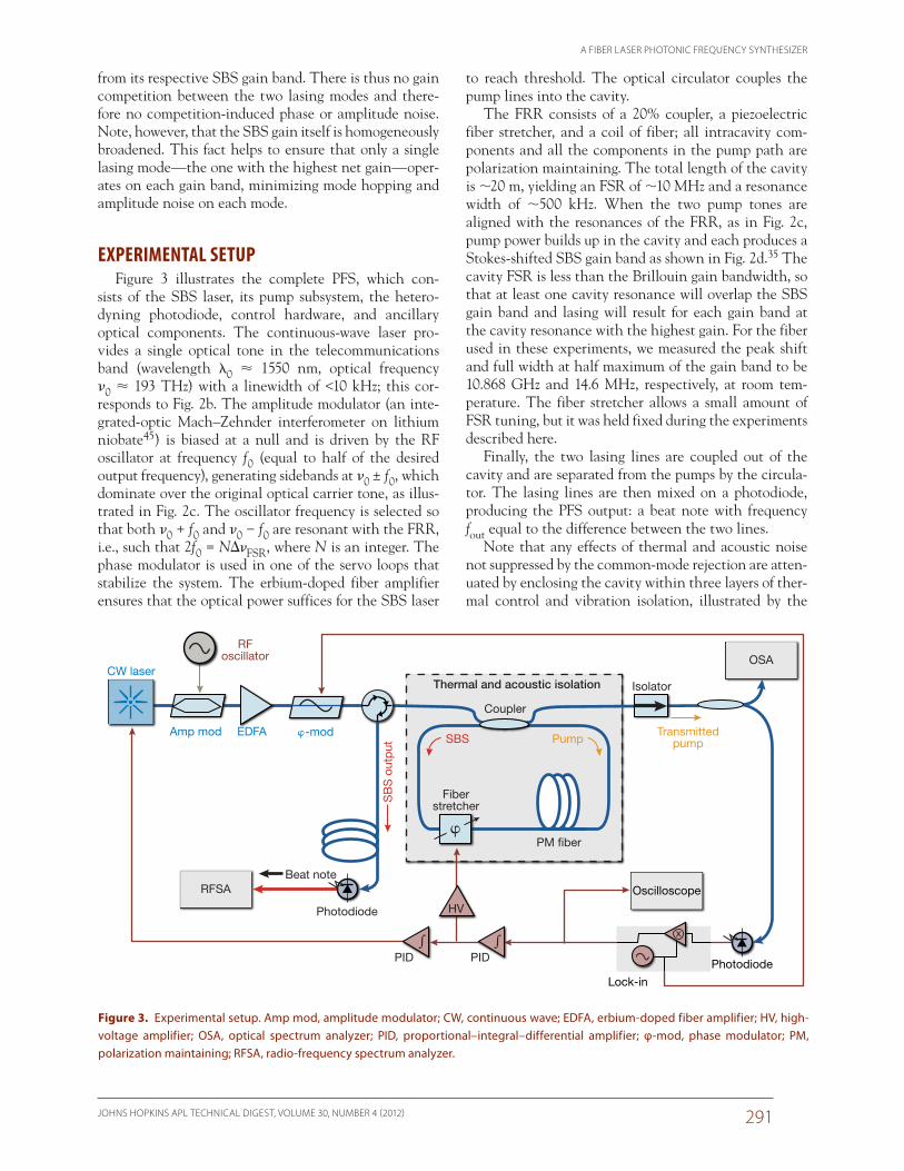
EXPERIMENTAL SETUPFigure 3 illustrates the complete PFS, which con-
sists of the SBS laser, its pump subsystem, the hetero-dyning photodiode, control hardware, and ancillary optical components. The continuous-wave laser pro-vides a single optical tone in the telecommunications band (wavelength l0 1550 nm, optical frequency 0 193 THz) with a linewidth of <10 kHz; this cor-responds to Fig. 2b. The amplitude modulator (an inte-grated-optic Mach–Zehnder interferometer on lithium niobate45) is biased at a null and is driven by the RF oscillator at frequency f0 (equal to half of the desired output frequency), generating sidebands at 0 ± f0, which dominate over the original optical carrier tone, as illus-trated in Fig. 2c. The oscillator frequency is selected so that both 0 + f0 and 0 − f0 are resonant with the FRR, i.e., such that 2f0 = NDFSR, where N is an integer. The phase modulator is used in one of the servo loops that stabilize the system. The erbium-doped fiber amplifier ensures that the optical power suffices for the SBS laser
x
Coupler
Thermal and acoustic isolation
PM �ber
HV
Amp mod
RFoscillator
Fiberstretcher
EDFA
OSA
Photodiode
Beat note
PID PID
�-mod
CW laser
SB
S o
utp
ut
Transmittedpump
� �
SBS Pump
Isolator
Photodiode
Lock-in
OscilloscopeRFSA
�
Figure 3. Experimental setup. Amp mod, amplitude modulator; CW, continuous wave; EDFA, erbium-doped fiber amplifier; HV, high-voltage amplifier; OSA, optical spectrum analyzer; PID, proportional–integral–differential amplifier; φ-mod, phase modulator; PM, polarization maintaining; RFSA, radio-frequency spectrum analyzer.

M. C. GROSS, P. T. CALLAHAN, AND M. L. DENNIS
JOHNS HOPKINS APL TECHNICAL DIGEST, VOLUME 30, NUMBER 4 (2012)292
The trace shown is a single spectrum; different compo-nents have been colored for illustrative purposes. The black components are the initial pump laser output at 0 (indicated by the arrow) and the modulation side-bands created by modulating at f0 = 4.175 GHz. In this early experiment, a phase modulator was used for the f0 modulation, resulting in numerous higher-order side-bands and substantial residual power at the original pump laser frequency. More recent experiments have used an intensity modulator, as diagramed in Fig. 3 and described above, which yields much weaker higher-order sidebands and minimal residual power at 0. The red lines are SBS products, each of which is downshifted by B from its pump. This experiment was conducted at an elevated temperature, so the Brillouin shift is 11.1 GHz.47 Because there are seven pump lines (the ini-tial pump, two first-order sidebands, two second-order sidebands, and two third-order sidebands), there are also seven SBS lines. Only the center three SBS lines are above the lasing threshold, and therefore they are substantially taller than the other red lines. The central pump tone was not suppressed, as noted above, so its SBS line is also above threshold. In our recent experi-ments this tone has been carefully minimized so no SBS lasing results from it.
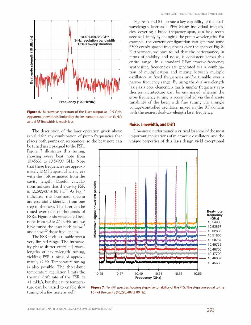
Microwave Characterization and TunabilityFigure 6 shows the microwave spectrum of a 10.5-GHz
beat note. The apparent linewidth in this trace is lim-ited by the 3-Hz resolution of the spectrum analyzer. As will be discussed in the next subsection, we have shown the true instantaneous linewidth to be much less.
dashed box in Fig. 3. The syn-thesizer is further stabilized via two servo loops. The first servo is a high-bandwidth (2-kHz) Pound–Drever–Hall loop46 that uses a phase dither of 100 kHz and a lock-in amplifier to detect the positions of the pump lines with respect to the cavity reso-nances and to keep those reso-nances locked to the pump tones by tuning the cavity length via the fiber stretcher. The second loop is a much lower-bandwidth (<100-Hz) servo that integrates the correction signal from the first loop to drive the fine-tun-ing port of the master pump laser, thus tracking the pump laser to the cavity. With these nested servo loops in place, locking of the pump and cavity can be maintained over periods of hours.
Figure 4 is a photograph of the packaged SBS laser at the core of PFS. The rack-mountable chassis shown in the photo contains the elements shown inside the dashed box in Fig. 3 in addition to the circulator and isolator. On the left are a main power switch, a second toggle switch for disabling the central layer of heaters, and three temperature controllers, each of which is responsible for one layer of heaters. On the right are opti-cal connectors for the pump input, transmitted pump output, and SBS lasing output, as well as an electrical connector for fiber-stretcher control voltage. An unused optical connector is also present so that an additional output can be easily added later.
PERFORMANCEOptical Characterization
An optical spectrum of the pump and Stokes lines during operation at 8.350 GHz is shown in Fig. 5.
Figure 4. Photograph of the rack-mountable chassis containing the SBS laser.
193.397500 THz (1550.1362 nm)
fout = 8.350 GHz
�B � 11 GHz
Op
tica
l po
wer
(10
dB
/div
)
Optical frequency (5 GHz/div)
Initialpump tone
Figure 5. High-resolution optical spectrum of the optical pump and the Brillouin laser for a beat frequency of 8.350 GHz. The black trace shows the initial pump laser and its modulation sidebands. The red trace shows the SBS from the pump laser and its modulation sidebands. fout, output frequency; B, Brillouin shift.
A FIBER LASER PHOTONIC FREQUENCY SYNTHESIZER
JOHNS HOPKINS APL TECHNICAL DIGEST, VOLUME 30, NUMBER 4 (2012) 293
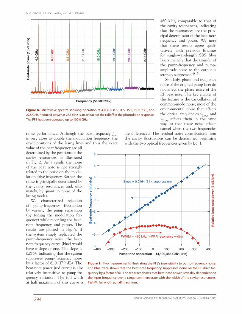
The description of the laser operation given above is valid for any combination of pump frequencies that places both pumps on resonances, so the beat note can be tuned in steps equal to the FSR. Figure 7 illustrates this tuning, showing every beat note from 10.45633 to 10.54900 GHz. Note that these frequencies are approxi-mately 10 MHz apart, which agrees with the FSR estimated from the cavity length. Careful calcula-tions indicate that the cavity FSR is 10,290,487 ± 80 Hz.20 As Fig. 7 indicates, the beat-note spectra are essentially identical from one step to the next. The laser can be tuned over tens of thousands of FSRs. Figure 8 shows selected beat notes from 4.0 to 27.5 GHz, and we have tuned the laser both below17 and above20 those frequencies.
The FSR itself is tunable over a very limited range. The intracav-ity phase shifter offers 4 wave-lengths of cavity-length tuning, yielding FSR tuning of approxi-mately ±2 Hz. Temperature tuning is also possible. The three-layer temperature regulation limits the thermal drift rate of the FSR to <1 mHz/s, but the cavity tempera-ture can be varied to enable slow tuning of a few hertz as well.
Figures 7 and 8 illustrate a key capability of the dual-wavelength laser as a PFS: Many individual frequen-cies, covering a broad frequency span, can be directly accessed simply by changing the pump wavelengths. For example, the current configuration can generate some 2300 evenly spaced frequencies over the span of Fig. 8. Furthermore, we have found that the performance, in terms of stability and noise, is consistent across this entire range. In a standard RF/microwave-frequency synthesizer, frequencies are generated via a combina-tion of multiplication and mixing between multiple oscillators at fixed frequencies and/or tunable over a narrow frequency range. By using the dual-wavelength laser as a core element, a much simpler frequency syn-thesizer architecture can be envisioned wherein the gross frequency tuning is accomplished via the discrete tunability of the laser, with fine tuning via a single voltage-controlled oscillator, mixed in the RF domain with the nearest dual-wavelength laser frequency.
Noise, Linewidth, and DriftLow-noise performance is critical for some of the most
important applications of microwave oscillators, and the unique properties of this laser design yield exceptional
10.5490010.5386710.5283310.51800
10.5076710.49733
10.4870010.4770010.46667
10.45633
10.5510.5310.5110.49Frequency (GHz)
Beat-notefrequency
(GHz)
Mic
row
ave
sig
nal p
ow
er (2
0 p
er/d
iv)
10.4710.45
Figure 7. Ten RF spectra showing stepwise tunability of the PFS. The steps are equal to the FSR of the cavity (10,290,487 ± 80 Hz).
Bea
t-no
te s
tren
gth
(10
dB
/div
)
Frequency (100 Hz/div)
10.497409723 GHz3-Hz resolution bandwidth
1.26-s sweep duration
Figure 6. Microwave spectrum of the laser output at 10.5 GHz. Apparent linewidth is limited by the instrument resolution (3 Hz); actual RF linewidth is much less.
M. C. GROSS, P. T. CALLAHAN, AND M. L. DENNIS
JOHNS HOPKINS APL TECHNICAL DIGEST, VOLUME 30, NUMBER 4 (2012)294
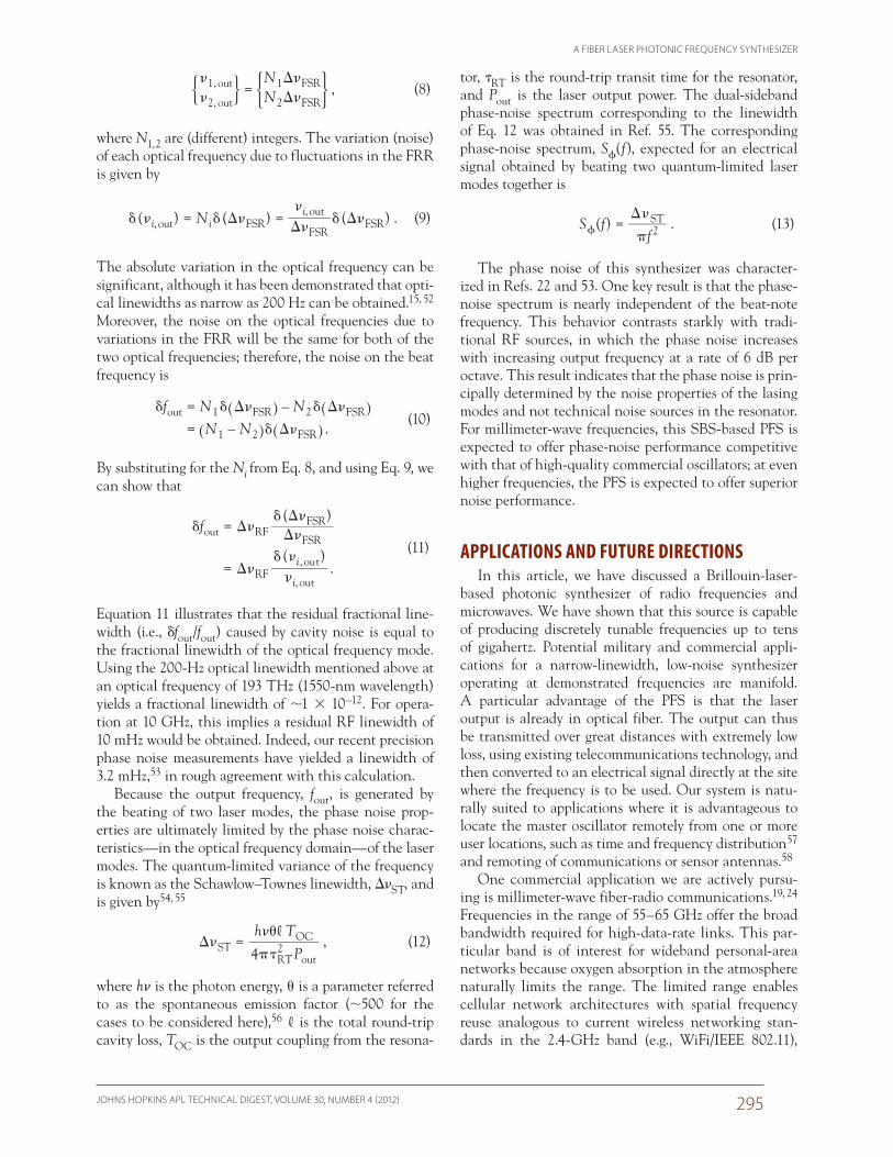
460 kHz, comparable to that of the cavity resonances, indicating that the resonances are the prin-cipal determinant of the beat-note frequency and power. We note that these results agree quali-tatively with previous findings for single-wavelength SBS fiber lasers, namely that the transfer of the pump-frequency and pump-amplitude noise to the output is strongly suppressed.48–51
Similarly, phase and frequency noise of the original pump laser do not affect the phase noise of the RF beat note. The key enabler of this feature is the cancellation of common-mode noise; most of the environmental noise that affects the optical frequencies 1, out and 2, out affects them in the same way, so that these noise effects cancel when the two frequencies
are differenced. The residual noise contributions from the cavity fluctuations can be determined beginning with the two optical frequencies given by Eq. 1,
noise performance. Although the beat frequency fout is very close to double the modulation frequency, the exact positions of the lasing lines and thus the exact value of the beat frequency are all determined by the positions of the cavity resonances, as illustrated in Fig. 2. As a result, the noise of the beat note is not strongly related to the noise on the modu-lation drive frequency. Rather, the noise is principally determined by the cavity resonances and, ulti-mately, by quantum noise of the lasing modes.
We characterized rejection of pump-frequency fluctuation by varying the pump separation (by tuning the modulation fre-quency) while recording the beat-note frequency and power. The results are plotted in Fig. 9. If the system simply replicated the pump-frequency noise, the beat-note frequency curve (blue) would have a slope of one. The slope is 0.0164, indicating that the system suppresses pump-frequency noise by a factor of 61.0 (17.9 dB). The beat-note power (red curve) is also relatively insensitive to pump-fre-quency variation. The full width at half maximum of this curve is
Slope = 0.0164 (61� suppression)
8
6
4
2
0
–2
–4
–6
–8–400 –300 –200 –100 0
Pump tone separation – 14,190,486 GHz (kHz)
FWHM � 460 kHz (�FRR resonance width)
100 200 300 400
Bea
t-not
e fr
eque
ncy
shift
(kH
z)
Rel
ativ
e be
at-n
ote
pow
er (6
dB
/div
)
Figure 9. Two measurements illustrating the PFS’s insensitivity to pump-frequency noise. The blue trace shows that the beat-note frequency suppresses noise on the RF drive fre-quency by a factor of 61. The red trace shows that beat-note power is weakly dependent on the input frequency over a range commensurate with the width of the cavity resonances. FWHM, full width at half maximum.
Frequency (50 MHz/div)
Bea
t-not
e po
wer
(10
dB/d
iv)
4.0
GH
z
6.0
GH
z
8.5
GH
z
11.5
GH
z
15.0
GH
z
19.0
GH
z
23.5
GH
z
27.5
GH
z
Figure 8. Microwave spectra showing operation at 4.0, 6.0, 8.5, 11.5, 15.0, 19.0, 23.5, and 27.5 GHz. Reduced power at 27.5 GHz is an artifact of the rolloff of the photodiode response. The PFS has been operated up to 100.0 GHz.
A FIBER LASER PHOTONIC FREQUENCY SYNTHESIZER
JOHNS HOPKINS APL TECHNICAL DIGEST, VOLUME 30, NUMBER 4 (2012) 295
tor, tRT is the round-trip transit time for the resonator, and Pout is the laser output power. The dual-sideband phase-noise spectrum corresponding to the linewidth of Eq. 12 was obtained in Ref. 55. The corresponding phase-noise spectrum, S(f), expected for an electrical signal obtained by beating two quantum-limited laser modes together is
( ) .S ff2ST
�
��=� (13)
The phase noise of this synthesizer was character-ized in Refs. 22 and 53. One key result is that the phase-noise spectrum is nearly independent of the beat-note frequency. This behavior contrasts starkly with tradi-tional RF sources, in which the phase noise increases with increasing output frequency at a rate of 6 dB per octave. This result indicates that the phase noise is prin-cipally determined by the noise properties of the lasing modes and not technical noise sources in the resonator. For millimeter-wave frequencies, this SBS-based PFS is expected to offer phase-noise performance competitive with that of high-quality commercial oscillators; at even higher frequencies, the PFS is expected to offer superior noise performance.
APPLICATIONS AND FUTURE DIRECTIONSIn this article, we have discussed a Brillouin-laser-
based photonic synthesizer of radio frequencies and microwaves. We have shown that this source is capable of producing discretely tunable frequencies up to tens of gigahertz. Potential military and commercial appli-cations for a narrow-linewidth, low-noise synthesizer operating at demonstrated frequencies are manifold. A particular advantage of the PFS is that the laser output is already in optical fiber. The output can thus be transmitted over great distances with extremely low loss, using existing telecommunications technology, and then converted to an electrical signal directly at the site where the frequency is to be used. Our system is natu-rally suited to applications where it is advantageous to locate the master oscillator remotely from one or more user locations, such as time and frequency distribution57 and remoting of communications or sensor antennas.58
One commercial application we are actively pursu-ing is millimeter-wave fiber-radio communications.19, 24 Frequencies in the range of 55–65 GHz offer the broad bandwidth required for high-data-rate links. This par-ticular band is of interest for wideband personal-area networks because oxygen absorption in the atmosphere naturally limits the range. The limited range enables cellular network architectures with spatial frequency reuse analogous to current wireless networking stan-dards in the 2.4-GHz band (e.g., WiFi/IEEE 802.11),
NN
1
2
1, out
2, out
FSR
FSR
�
�
�
�
�
�=' )1 3 , (8)
where N1, 2 are (different) integers. The variation (noise) of each optical frequency due to fluctuations in the FRR is given by
( ) ( ) ( ) .N,,
out FSRFSR
outFSRi i
i� � � �
�
�� ��
��= = (9)
The absolute variation in the optical frequency can be significant, although it has been demonstrated that opti-cal linewidths as narrow as 200 Hz can be obtained.15, 52 Moreover, the noise on the optical frequencies due to variations in the FRR will be the same for both of the two optical frequencies; therefore, the noise on the beat frequency is
.
f N NN N
––
out 1 FSR 2 FSR
1 2 FSR
� � � � �
� �
� �
�
==
^ ^^ ^
h hh h
(10)
By substituting for the Ni from Eq. 8, and using Eq. 9, we can show that
( )
( ).
f
,i
i
out RFFSR
FSR
RFout
out,
� ��
� �
��
� �
��
�
�
=
= (11)
Equation 11 illustrates that the residual fractional line-width (i.e., dfout/fout) caused by cavity noise is equal to the fractional linewidth of the optical frequency mode. Using the 200-Hz optical linewidth mentioned above at an optical frequency of 193 THz (1550-nm wavelength) yields a fractional linewidth of 1 10–12. For opera-tion at 10 GHz, this implies a residual RF linewidth of 10 mHz would be obtained. Indeed, our recent precision phase noise measurements have yielded a linewidth of 3.2 mHz,53 in rough agreement with this calculation.
Because the output frequency, fout, is generated by the beating of two laser modes, the phase noise prop-erties are ultimately limited by the phase noise charac-teristics—in the optical frequency domain—of the laser modes. The quantum-limited variance of the frequency is known as the Schawlow–Townes linewidth, DST, and is given by54, 55
,P
h T
4STRT2
out
OC,�
��
��� = (12)
where h is the photon energy, u is a parameter referred to as the spontaneous emission factor (500 for the cases to be considered here),56 , is the total round-trip cavity loss, TOC is the output coupling from the resona-
M. C. GROSS, P. T. CALLAHAN, AND M. L. DENNIS
JOHNS HOPKINS APL TECHNICAL DIGEST, VOLUME 30, NUMBER 4 (2012)296
to absolute physical references such as a molecular or atomic absorption line. Acetylene and cyanide stan-dards exist in the 1550-nm region where our system operates,63, 64 and a technique for high-precision stabili-zation of a 1556-nm source to a 85Rb reference has been demonstrated.61 Thus, this is a practical direction for future research. We are pursuing multiple approaches for attaining exceptionally low phase noise, with the objec-tive of developing precision sources competitive with the best available microwave oscillators.65
ACKNOWLEDGEMENTS: The research reported in this article was supported by internal research and devel-opment funding by the APL Air and Missile Defense Business Area.
REFERENCES 1Lim, C., Nirmalathas, A., Bakaul, M., Lee, K.-L., Novak, D., and
Waterhouse, R., “Mitigation Strategy for Transmission Impairments in Millimeter-Wave Radio-Over-Fiber Networks,” J. Opt. Netw. 8(2), 201–214 (2009).
2Gomes, N. J., Morant, M., Alphones, A., Cabon, B., Mitchell, J. E., et al., “Radio-Over-Fiber Transport for the Support of Wireless Broadband Services,” J. Opt. Netw. 8(2), 156–178 (2009).
3Stralka, J. P., and Fedarko, W. M., “Pulse Doppler Radar,” in Radar Handbook, 3rd Ed., M. Skolnik (ed.), McGraw-Hill, New York, pp. 4.1–4.53 (2008).
4Williams, K. J., Goldberg, L., Esman, R. D., Dagenais, M., and Weller, J. F., “6–34 GHz Offset Phase-Locking of Nd:YAG 1319 nm Nonpla-nar Ring Lasers,” Electron. Lett. 25(18), 1242–1243 (1989).
5Simonis, G. J., and Purchase, D. G., “Optical Generation, Distribu-tion, and Control of Microwaves Using Laser Heterodyne,” IEEE Trans. Microw. Theory Tech. 38(5), 667–669 (1990).
6Cliche, J.-F., Shillue, B., Têtu, M., and Poulin, M., “A 100-GHz- Tunable Photonic Millimeter Wave Synthesizer for the Atacama Large Millimeter Array Radiotelescope,” in IEEE/MTT-S Interna-tional Microwave Symp., 2007, Honolulu, HI, pp. 349–352 (2007).
7Loh, W. H., de Sandro, J. P., Dowle, G. J., Samson, B. N., and Ellis, A. D., “40 GHz Optical-Millimetre Wave Generation with a Dual Polarization Distributed Feedback Fibre Laser,” Electron. Lett. 33(7), 594–595 (1997).
8Pajarola, S., Guekos, G., Nizzola, P., and Kawagucki, H., “Dual-Polarization External-Cavity Diode Laser Transmitter for Fiber-Optic Antenna Remote Feeding,” IEEE Trans. Microw. Theory Tech. 47(7), 1234–1240 (1999).
9Clark, T. R., Airola, M. G., and Sova, R. M., “Demonstration of Dual-Polarization Fiber Ring Laser for Microwave Generation,” in IEEE International Topical Meeting on Microwave Photonics, 2004, Ogun-quit, ME, pp. 127–130 (2004).
10Pillet, G., Morvan, L., Brunel, M., Bretenaker, F., Dolfi, D., et al., “Dual-Frequency Laser at 1.5 mm for Optical Distribution and Gen-eration of High-Purity Microwave Signals,” J. Lightw. Tech. 26(15), 2764–2773 (2008).
11Zhou, J. L., Xia, L., Cheng, X. P., Dong, X. P., and Shum, P., “Pho-tonic Generation of Tunable Microwave Signals by Beating a Dual-Wavelength Single Longitudinal Mode Fiber Ring Laser,” Appl. Phys. B 91(1), 99–103 (2008).
12Pan, S. L., and Yao, J. P., “A Wavelength-Switchable Single-Longitu-dinal-Mode Dual-Wavelength Erbium-Doped Fiber Laser for Tunable Microwave Generation,” Opt. Express 17(7), 5414–5419 (2009).
13Demtröder, W., Laser Spectroscopy: Basic Concepts and Instrumenta-tion, 3rd Ed., Springer, Berlin (2003).
14Siegman, A. E., Lasers, University Science Books, Mill Valley, CA, pp. 992–1003 (1986).
but with vastly enhanced bandwidth. We have demon-strated data transport up to 3 Gb/s over distances up to 100 m, as described by Nanzer et al. elsewhere in this issue.
We believe that operation at much higher frequen-cies can be realized. In our current setup, the beat-note frequency is limited by the RF oscillator, the amplitude modulator, and the photodetector. We can eliminate the oscillator and the modulator by using two separate lasers to provide the two pump tones.16 These lasers can be arbitrarily far apart in frequency; at least one must be tunable in order to tune the beat note. The beat frequency from the SBS modes would be expected to have noise and stability properties comparable to what has been demonstrated in this work because of the common-cavity/common-mode noise-rejection mecha-nisms described above. With dual-laser pumping, the output frequency is limited only by the electrical band-width of the photodiode. Detector technology is advanc-ing steadily, with 100-GHz photodiodes commercially available (e.g., from u2t Photonics AG of Berlin, Ger-many) and >300-GHz devices demonstrated.59 These developments open up the prospect of using this tech-nology for applications in the submillimeter-wave and tetrahertz-frequency regimes. Frequencies from 90 to 400 GHz are of interest for communications links, offering extremely high bandwidths for data-intensive applications such as multisensory telepresence and transmitting hyperspectral video. Certain frequency bands in the millimeter-wave regime can propagate through dust and other adverse atmospheric conditions; however, for commercially available power levels, range in the atmosphere is limited to 9000 m through clear air, depending on wavelength.60 Rain and foliage reduce this range considerably. Frequencies in this range allow very small antennas, which are crucial for miniature UAVs and microsatellites. Atmospheric absorption is absent in outer space, so these frequency bands are especially compelling for high-bandwidth intersatellite cross-links.
Other potential applications for a PFS exist in research and development. One unique application is distribution of the master oscillator in millimeter-wave radio astronomy arrays. The Atacama Large Millimeter Array uses fiber-optic distribution of the master oscilla-tor to coherently phase the receivers in the individual telescopes using a complex optical phase-locked loop.61 The PFS would have advantages over the current meth-ods, including simpler construction, superior phase noise over a broad band of offset frequencies, and greater frequency flexibility. Additionally, the PFS offers ben-efits in the field of precision terahertz spectroscopy by extending the precision currently attainable at micro-wave frequencies into the tetrahertz regime.62
High-precision applications, such as spectroscopy and navigation, would require long-term stabilization
A FIBER LASER PHOTONIC FREQUENCY SYNTHESIZER
JOHNS HOPKINS APL TECHNICAL DIGEST, VOLUME 30, NUMBER 4 (2012) 297
37Smith, S. P., Zarinetchi, F., and Ezekiel, S., “Narrow Linewidth Stimu-lated Brillouin Fiber Laser and Applications,” Opt. Lett. 16(6), 393–395 (1991).
38Thomas, P. J., van Driel, H. M., and Stegeman, G. I. A., “Possibility of Using an Optical Fiber Brillouin Ring Laser for Inertial Sensing,” Appl. Opt. 19(12), 1906–1908 (1980).
39Vali, V., and Shorthill, R. W., “Stimulated Brillouin Scattering Ring Laser Gyroscope,” U.S. Patent 4,159,178 (26 June 1979).
40Kadiwar, R. K., and Giles, I. P., “Optical Fibre Brillouin Ring Laser Gyroscope,” Electron. Lett. 25(25), 1729–1731 (1989).
41Dyes, W. A., and Farhad, H., “Scattered Light Multi-Brillouin Gyro-scope,” U.S. Patent 5,064,288 (12 Nov 1991).
42Zarinetchi, F., Smith, S. P., and Ezekiel, S., “Stimulated Brillouin Fiber-Optic Gyroscope,” Opt. Lett. 16(4), 229–231 (1991).
43Quast, T., and Raab, M., “Brillouin Ring Laser,” U.S. Patent 5,323,415 (21 June 1994).
44Raab, M., “Brillouin Ring Laser Gyro,” U.S. Patent 5,517,305 (14 May 1996).
45Wooten, E. L., Kissa, K. M., Yi-Yan, A., Murphy, E. J., Lafaw, D. A., et al., “A Review of Lithium Niobate Modulators for Fiber-Optic Communications Systems,” IEEE. J. Sel. Top. Quantum Electron. 6(1), 69–82 (2000).
46Black, E. D., “An Introduction to Pound-Drever-Hall Laser Frequency Stabilization,” Am. J. Phys. 69(1), 79–87 (2001).
47Yu, Q., Bao, X., and Chen, L., “Temperature Dependence of Brill-ouin Frequency, Power, and Bandwidth in Panda, Bow-Tie, and Tiger Polarization-Maintaining Fibers,” Opt. Lett. 29(1), 17–19 (2004).
48Debut, A., Randoux, S., and Zemmouri, J., “Linewidth Narrowing in Brillouin Lasers: Theoretical Analysis,” Phys. Rev. A 62(2), 023803-1–023803-4 (2000).
49Debut, A., Randoux, S., and Zemmouri, J., “Experimental and Theo-retical Study of Linewidth Narrowing in Brillouin Fiber Ring Lasers,” J. Opt. Soc. Am. B 18(4), 556–567 (2001).
50Stépien, L., Randoux, S., and Zemmouri, J., “Intensity Noise in Bril-louin Fiber Ring Lasers,” J. Opt. Soc. Am. B 19(5), 1055–1066 (2002).
51Molin, S., Baili, G., Alouini, M., Dolfi, D., and Huignard, J.-P., “Experimental Investigation of Relative Intensity Noise in Brillouin Fiber Ring Lasers for Microwave Photonics Applications,” Opt. Lett. 33(15), 1681–1683 (2008).
52Geng, J., Staines, S., Wang, Z., Zong, J., Blake, M., and Jiang, S., “Actively Stabilized Brillouin Fiber Laser with High Output Power and Low Noise,” in Optical Fiber Communication Conf., 2006 and the 2006 National Fiber Optic Engineers Conf. (OFC 2006), Anaheim, CA, paper OThC4 (2006).
53Callahan, P. T., Gross, M. C., and Dennis, M. L., “Frequency-Inde-pendent Phase Noise of a Dual-Wavelength Brillouin Fiber Laser,” IEEE J. Quantum Electron. (in press).
54Schawlow, A. L., and Townes, C. H., “Infrared and Optical Masers,” Phys. Rev. 112(6), 1940–1949 (1958).
55Paschotta, R., Schlatter, A., Zeller, S. C., Telle, H. R., and Keller, U., “Optical Phase Noise and Carrier-Envelope Offset Noise of Mode-Locked Lasers,” Appl. Phys. B 82(2), 265–273 (2006).
56Olsson, N. A., and Van Der Ziel, J. P., “Characteristics of a Semicon-ductor Laser Pumped Brillouin Amplifier with Electronically Con-trolled Bandwidth,” J. Lightw. Technol. LT-5(1), 147–153 (1987).
57Ye, J., Peng, J.-L., Jones, R. J., Holman, K. W., Hall, J. L., et al., “Deliv-ery of High-Stability Optical and Microwave Frequency Standards over an Optical Fiber Network,” J. Opt. Soc. Am. B 20(7), 1459–1467 (2003).
58Seeds, A. J., “Microwave Photonics,” IEEE Trans. Microw. Theory Tech. 50(3), 877–887 (2002).
59Beling, A., and Campbell, J. C., “InP-Based High-Speed Photodetec-tors,” J. Lightw. Technol. 27(3), 343–355 (2009).
60Marcus, M., and Pattan, B., “Millimeter Wave Propagation: Spectrum Management Implications,” IEEE Microw. Mag. 6(2), 54–62 (2005).
61Cliche, J.-F., Shillue, B., Latrasse, C., Têtu, M., and D’Addario, L., “A High Coherence, High Stability Laser for the Photonic Local Oscilla-tor Distribution of the Atacama Large Millimeter Array,” in Ground-based Telescopes, Proc. SPIE, Vol. 5489, J. M. Oschmann Jr. (ed.), SPIE, Bellingham, WA, pp. 1115–1126 (2004).
15Geng, J., Staines, S., Wang, Z., Zong, J., Blake, M., and Jiang, S., “Highly Stable Low-Noise Brillouin Fiber Laser with Ultranarrow Spectral Linewidth,” IEEE Photonics Technol. Lett. 18(17), 1813–1815 (2006).
16Geng, J. H., Staines, S., and Jiang, S. B., “Dual-Frequency Brillouin Fiber Laser for Optical Generation of Tunable Low-Noise Radio Fre-quency/Microwave Frequency,” Opt. Lett. 33(1), 16–18 (2008).
17Dennis, M. L., Sova, R. M., and Clark, T. R., “Dual-Wavelength Bril-louin Fiber Laser for Microwave Frequency Generation,” in Conf. on Optical Fiber Communication and the National Fiber Optic Engineers Conf., 2007, Anaheim, CA, paper OWJ6 (2007).
18Dennis, M. L., Sova, R. M., and Clark, T. R., “Microwave Frequency Generation up to 27.5 GHz Using a Dual-Wavelength Brillouin Fiber Laser,” in 2007 Digest of the IEEE/LEOS Summer Topical Meetings, Portland, OR, pp. 194–195 (2007).
19Dennis, M. L., Gross, M. C., Clark, T. R., Novak, D., and Waterhouse, R. B., “Broadband Data Transmission in a 40 GHz Fiber Radio Link Using a Dual-Wavelength SBS Fiber Laser,” in Conf. on Optical Fiber Communication and the National Fiber Optic Engineers Conf., San Diego, CA, paper OWF4 (2009).
20Gross, M. C., Callahan, P. T., Clark, T. R., Novak, D., Waterhouse, R. B., and Dennis, M. L., “Tunable Millimeter-Wave Frequency Synthe-sis Up to 100 GHz by Dual-Wavelength Brillouin Fiber Laser,” Opt. Express 18(13), 13321–13330 (2010).
21Gross, M. C., Clark, T. R., and Dennis, M. L., “Narrow-Linewidth Microwave Frequency Generation by Dual-Wavelength Brillouin Fiber Laser,” in 21st Annual Meeting of the IEEE Lasers and Electro-Optics Society, 2008 (LEOS 2008), Newport Beach, CA, pp. 151–152 (2008).
22Callahan, P. T., Gross, M. C., and Dennis, M. L., “Phase Noise Mea-surements of a Dual-Wavelength Brillouin Fiber Laser,” in 2010 IEEE Topical Meeting on Microwave Photonics (MWP), Montreal, QC, Canada, pp. 155–158 (2010).
23Dennis, M. L., Callahan, P. T., and Gross, M. C., “Suppression of Rel-ative Intensity Noise in a Brillouin Fiber Laser by Operation Above Second-Order Threshold,” in 23rd Annual Meeting of the IEEE Pho-tonics Society, 2010, Denver, CO, pp. 28–29 (2010).
24Dennis, M. L., Nanzer, J. A., Callahan, P. T., Gross, M. C., Clark, T. R., et al., “Photonic Upconversion of 60 GHz IEEE 803.15.3c Stan-dard Compatible Data Signals Using a Dual-Wavelength Laser,” in 23rd Annual Meeting of the IEEE Photonics Society, 2010, Denver, CO, pp. 383–384 (2010).
25Stokes, L. F., Chodorow, M., and Shaw, H. J., “All-Single Mode Fiber Resonator,” Opt. Lett. 7(6), 288–290 (1982).
26Meyer, R. E., Ezekiel, S., Stowe, D. W., and Tekippe, V. J., “Passive Fiber-Optic Ring Resonator for Rotation Sensing,” Opt. Lett. 8(12), 644–646 (1983).
27Hotate, K., “Fiber Sensor Technology Today,” Opt. Fiber Technol. 3(4), 356–402 (1997).
28Yue, C. Y., Peng, J. D., Liao, Y. B., and Zhou, B. K., “Fiber Ring Reso-nator with Finesse of 1260,” Electron. Lett. 24(10), 622–623 (1988).
29Tai, S., Kyuma, K., Hamanaka, K., and Nakayama, T., “Applications of Fibre Optic Ring Resonators Using Laser Diodes,” Optica Acta 33(12), 1539–1551 (1986).
30Kalli, K., and Jackson, D. A., “Ring Resonator Optical Spectrum Ana-lyzer with 20-kHz Resolution,” Opt. Lett. 17(15), 1090–1092 (1992).
31Agrawal, G. P., Nonlinear Fiber Optics, 2nd Ed., Academic Press, San Diego (1995).
32Niklès, M., Thévenaz, L., and Robert, P. A., “Brillouin Gain Spec-trum Characterization in Single-Mode Optical Fibers,” J. Lightw. Technol. 15(10), 1842–1851 (1997).
33Hill, K. O., Kawasaki, B. S., and Johnson, D. C., “CW Brillouin Laser,” Appl. Phys. Lett. 28(10), 608–609 (1976).
34Ponikvar, D. R., and Ezekiel, S., “Stabilized Single-Frequency Stimu-lated Brillouin Fiber Ring Laser,” Opt. Lett. 6(8), 398–400 (1981).
35Stokes, L. F., Chodorow, M., and Shaw, H. J., “All-Fiber Stimulated Brillouin Ring Laser with Submilliwatt Pump Threshold,” Opt. Lett. 7(10), 509–511 (1982).
36Smith, D. W., Cotter, D., and Wyatt, R., “Method and Apparatus for Generating Coherent Radiation,” U.S. Patent 4,780,876 (25 Oct 1988).

M. C. GROSS, P. T. CALLAHAN, AND M. L. DENNIS
JOHNS HOPKINS APL TECHNICAL DIGEST, VOLUME 30, NUMBER 4 (2012)298
64Gilbert, S. L., Swann, W. C., and Wang, C. M., Hydrogen Cyanide H13C14N Absorption Reference for 1530–1560 nm Wavelength Cali-bration—SRM 2519, National Institute of Standards and Technol-ogy Special Publication 260-137, U.S. Government Printing Office, Washington, DC (1998).
65Ivanov, E. N., and Tobar, M. E., “Low Phase-Noise Sapphire Crys-tal Microwave Oscillators: Current Status,” IEEE Trans. Ultrason. Ferroelectr. Freq. Control. 56(2), 263–269 (2009).
62De Lucia, F. F., “Spectroscopy in the Terahertz Spectral Region,” in Sensing with Terahertz Radiation, D. Mittleman (ed.), Springer, Berlin (2003).
63Gilbert, S. L., and Swann, W. C., Acetylene 12C2H2 Absorption Ref-erence for 1510 nm to 1540 nm Wavelength Calibration—SRM 2517a, National Institute of Standards and Technology Special Publication 260-133, 2001 Ed., U.S. Government Printing Office, Washington, DC (2001).
Michael C. Gross is a member of the Senior Pro-fessional Staff in APL’s Research and Exploratory Development Department. Dr. Gross was respon-sible for assembling the synthesizer and its envi-ronmental control, and he was instrumental in extending the system’s capabilities to millimeter-wave frequencies. Patrick T. Callahan was previ-ously a member of the Associate Professional Staff in the Electro-Optical and Infrared Systems and
Technology Group in APL’s Air and Missile Defense Department and is now with the Department of Electrical Engi-neering and Computer Science at the Massachusetts Institute of Technology. Mr. Callahan carried out extensive char-acterization of the synthesizer’s noise properties and was invaluable in the application of the system to high-frequency carrier and waveform synthesis and to millimeter-wave communications. Michael L. Dennis is a Principal Professional Staff member in the Air and Missile Defense Department and the Principal Investigator on this project. Dr. Dennis invented the dual-mode Brillouin synthesizer, constructed and tested the first prototype system, and was extensively involved in the work described here as well as in developing potential applications. For further information on the work reported here, contact Michael Gross. His e-mail address is [email protected].
The Authors
Patrick T. Callahan
Michael C. Gross
Michael L. Dennis
The Johns Hopkins APL Technical Digest can be accessed electronically at www.jhuapl.edu/techdigest.
![Glasses for Photonic Technologiesarticle.sapub.org/pdf/10.5923.j.optics.20130306.02.pdf · 6/3/2013 · bismuth-silicate photonic crystal fiber was accomplished[29]. Chromium-doped,](https://img.dokumen.tips/doc/110x75/606f991d5bb44122f22eb837/glasses-for-photonic-632013-bismuth-silicate-photonic-crystal-fiber-was-accomplished29.jpg)