Embed Size (px)
DESCRIPTION
A Dynamic Stiffness Element for Free Vibration Analysis ofDelaminated Layered Beams
Citation preview
Hindawi Publishing CorporationModelling and Simulation in EngineeringVolume 2012, Article ID 492415, 8 pagesdoi:10.1155/2012/492415
Research Article
A Dynamic Stiffness Element for Free Vibration Analysis ofDelaminated Layered Beams
Nicholas H. Erdelyi and Seyed M. Hashemi
Department of Aerospace Engineering, Ryerson University, 350 Victoria Street, Toronto, ON, Canada M5B 2K3
Correspondence should be addressed to Seyed M. Hashemi, [email protected]
Received 31 March 2011; Accepted 30 September 2011
Academic Editor: Jing-song Hong
Copyright © 2012 N. H. Erdelyi and S. M. Hashemi. This is an open access article distributed under the Creative CommonsAttribution License, which permits unrestricted use, distribution, and reproduction in any medium, provided the original work isproperly cited.
A dynamic stiffness element for flexural vibration analysis of delaminated multilayer beams is developed and subsequently used toinvestigate the natural frequencies and modes of two-layer beam configurations. Using the Euler-Bernoulli bending beam theory,the governing differential equations are exploited and representative, frequency-dependent, field variables are chosen based on theclosed form solution to these equations. The boundary conditions are then imposed to formulate the dynamic stiffness matrix(DSM), which relates harmonically varying loads to harmonically varying displacements at the beam ends. The bending vibrationof an illustrative example problem, characterized by delamination zone of variable length, is investigated. Two computer codes,based on the conventional Finite Element Method (FEM) and the analytical solutions reported in the literature, are also developedand used for comparison. The intact and defective beam natural frequencies and modes obtained from the proposed DSM methodare presented along with the FEM and analytical results and those available in the literature.
1. Introduction
Layered structures have seen greatly increased use in civil,shipbuilding, mechanical, and aerospace structural applica-tions in recent decades, primarily due to their many attractivefeatures, such as high specific stiffness, high specific strength,good buckling resistance, and formability into complexshapes, to name a few. The replacement of traditionally me-tallic structural components with laminated composites hasresulted in new and unique design challenges. Metallic struc-tures exhibit mainly isotropic material properties and failuremodes. By contrast, composite materials are anisotropic,which can result in more complex failure modes. Delamina-tion is a common failure mode in layered structures. It mayarise from loss of adhesion between two layers of the struc-ture, from interlaminar stresses arising from geometric ormaterial discontinuities, or from mechanical loadings. Thepresence of delamination may significantly reduce the stif-fness and strength of the structures. A reduction in the stiff-ness will affect the vibration characteristics of the structures,such as the natural frequencies and mode shapes. Changes inthe natural frequency, as a direct result of the reduction of
stiffness, may lead to resonance if the reduced frequency isclose to an excitation frequency.
The dynamic modeling of flexible delaminated multi-layer beams has been a topic of interest for many researchers.With the increase in use of laminated composite structures,the requirement for accurate delamination models has alsogrown. The earliest delamination models, formulated in the1980s [1], dealt with the vibration of two-layer sandwichbeams, where layers were governed by the Euler-Bernoullibending beam theory. The upper and lower intact portionsof the delaminated segment were assumed to vibrate freely—independent of each other; as a result, this model is knownas “free mode” delamination. It was later discovered that thefree mode underpredicted natural frequencies for off-mid-plane delaminations due to unrestricted penetration of thebeams into each other. This was accounted for in 1988[2] by constraining the transverse displacements of thetop and bottom beams to be equal. The resulting model,known as the “constrained mode” delamination model, pre-dicts vibration behaviour much more accurately for off-mid-plane delamination. However, in modeling terms, the con-strained mode is simply a limiting case of the free mode

2 Modelling and Simulation in Engineering
delamination model, from which it can be derived. Thus, inthe present study, the free mode delamination model will beinvestigated, and the constrained mode delamination modelcan be derived in the same manner as presented. It is alsoworth noting that, in general, a laminated composite beammay have orthotropic layerwise material properties, result-ing in displacement coupling behaviour. The model used inthis study assumes an isotropic material and is not readi-ly applicable to fibre-reinforced laminated composite beams,as there would, in general, be a torsional and/or extensionalresponse coupled with flexural vibration [3–5]. While themodel used in this study assumes an isotropic materials(i.e., no coupled response), the proposed technique couldbe extended—keeping the delamination continuity condi-tions—to include more realistic composite response.
The accuracy of dynamic analysis, and forced responsecalculation, of a flexible structure depends greatly on thereliability of the modal analysis method used and the result-ing natural frequencies and modes. There are various nu-merical, semianalytical, and analytical methods to extractthe natural frequencies of a system. The conventional FiniteElement Method (FEM) has a long well-established historyand is the most commonly used method for modal analysis.The FEM is a general systematic approach to formulate theconstant element mass and stiffness matrices for a given sys-tem and is easily adaptable to complex systems containingvariations in geometry or loading. Nonuniform geometry,for example, is often modeled as a stepped, piecewise-uni-form configuration. The conventional FEM formulation,based on polynomial shape functions, leads to constant massand stiffness matrices and results in a linear eigenvalue prob-lem from which the natural frequencies and modes of thesystem can be readily extracted. Lee [6], amongst others, in-vestigated the free vibration analysis of laminated beams withdelamination using a conventional FEM. Based on layerwisetheory, equations of motion were derived from Hamilton’sprinciple, a Finite Element Method (FEM) was developedto formulate the problem, and the effects of location, size,and number of delaminations on vibration frequencies ofdelaminated beams were investigated [6]. During the lastdecade, sandwich and composite elements have been madeavailable in some commercial software packages and are usedto analyze the vibration of composite structures.
Alternatively, one can use semianalytical formulations,such as the so-called Dynamic Finite Element (DFE) method[7, 8], to carry out structural modal analysis. The hybrid DFEformulation results in a more accurate prediction methodthan traditional and FEM modeling techniques, allowing fora reduced mesh size. The main principle of the DFE is theWeighted Residual Integral formulation, providing a generalsystematic modeling procedure. The word Dynamic in DFEacronym refers to the frequency-dependent shape functionsused to express the displacements, which in turn lead to thestiffness matrix of the system. The DFE technique follows thesame typical procedure as the FEM by formulating the ele-ment equations discretized to a local domain, where elementstiffness matrices are constructed and then assembled intoa single global matrix. The application of the DFE to free
vibration analysis of a delaminated 2-layer beam has beenreported in an earlier work by the authors [9].
Analytical methods, namely the dynamic stiffness matrix(DSM), have also been used for the vibrational analysis ofisotropic [10, 11], sandwich [12–14], and composite struc-tural elements [15] and beamstructures [15, 16]. The DSMapproach makes use of the general closed-form solution tothe governing differential equations of motion of the systemto formulate a frequency-dependent stiffness matrix. TheDSM describes the free vibration of the system and exhibitsboth inertia and stiffness properties of the syetem. Based onthis exact member theory, the DSM produces exact resultsfor simple structural elements, such as uniform beams, usingonly one element [10, 11]. Banerjee and his coworkers [10–16] have developed a number of DSM formulations for var-ious beam configurations, where the root-finding techniqueproposed by Wittrick-Williams (W-W) [17] was exploited todetermine the eigenvalues of the system. The DSM has alsobeen used by Wang et al. [18] to simulate a cracked beam.Wang [19] also investigated the effects of a through-thick-ness crack on the free vibration modes, aeroelastic flutter,and divergence of a composite wing. Borneman et al. [20]presented explicit expressions of a DSM for the coupledcomposite beams, exhibiting both material and geometriccouplings. These expressions were consequently used todevelop a cracked DSM formulation, and the free vibrationof doubly coupled cracked composite beams was investigat-ed. Given these considerations, the DSM method for a singlebeam can be modified to accurately model delaminated mul-tilayer beams. A DSM-based preliminary analysis of a two-layer split beam has laso been presented in an earlier work bythe authors [21].
The aim of this paper is to present a DSM formulation forthe free vibration analysis of a delaminated two-layer beam,using the free mode delamination model. The delaminationis represented by two intact beam segments; one for eachof the top and bottom sections of the delamination. Thedelaminated region is bounded on either side by intact, full-height beams. The beams transverse displacements are gov-erned by the Euler-Bernoulli slender beam bending theory.Shear deformation and rotary inertia, commonly associatedwith Timoshenko beam theory, are neglected. For harmonicoscillation, the governing equations are developed and usedas the basis for the DSM development. Continuities of forces,moments, displacements, and slopes at the delamination tipsare enforced, leading to the DSM of the system. Assemblyof element DSM matrices and the application of boundaryconditions results in the nonlinear eigenvalue problem ofthe defective system. In addition, two computer codes, basedon the conventional Finite Element Method (FEM) and theanalytical solutions reported in the literature [7, 8], takinginto account the same continuity conditions, are also devel-oped and used as a benchmark for comparison. The FEMmodel exploits cubic Hermite interpolation functions of ap-proximation to express the flexural displacement functions,that is, field variables and weighting functions [22, 23]. BothDSM and FEM models are used to compute the natural fre-quencies of an illustrative example problem characterizedby delamination zone of variable length. The frequency

Modelling and Simulation in Engineering 3
H2
H1H3Beam 1 Beam 4Beam 3
Beam 2
z,w,V
x,u,P
Through-width delamination
L1 L2,3, a L4
L
x = x1 x = x2 x = x3 x = x4
w, M
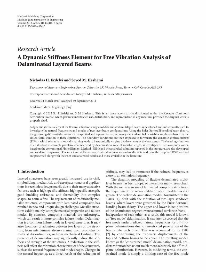
Figure 1: The coordinate system and notation for a delaminatedcomposite beam.
23
2
3
23
P2P2
P3 =
=
−P2P3
M2
M2
M3M3
Faces remainplanar afterdeformation
+
Figure 2: The faces of the delamination remain planar after defor-mation.
values are then compared with those from the literature. Cer-tain modal characteristics of the system are also discussed.
2. Mathematical Model
Figure 1 shows the general coordinate system and notationfor a delaminated beam, with total length L, intact beamsegment lengths L1 and L4, delamination length a, and totalheight H1. This model incorporates a general delamination,which can include laminated composites or bilayered iso-tropic materials, with different material and geometric prop-erties above and below the delamination plane. Thus, the toplayer has thickness H2, Young’s modulus E2, density ρ2, cross-sectional area A2, and second moment of area I2. The bottomlayer has corresponding properties, with subscript 3. Thedelamination tips occur at stations x2 and x3, and torsion,shear deformation, axial (warping effects and axial deforma-tion), and out-of-plane delamination are ignored. Followingthis notation, the general equation of motion for the ithEuler-Bernoulli beam in free vibration is written as [8, 9]:
EIi∂4wi
∂x4+ ρiAi
∂2wi
∂t2= 0, i = 1, . . . , 4. (1)
For harmonic oscillations, the transverse displacements canbe described in the frequency domain by using the trans-formation
wi(t) =Wi sin(ωt), (2)
where ω is the circular frequency of excitation of the system,Wi is the amplitude of the displacement wi, and subscript “i”represents the beam segment number. By backsubstituting(2) into (1), the equations of motion reduce to
EIi∂4Wi
∂x4− ρiAiω
2Wi = 0, i = 1, . . . , 4. (3)
The general solution to the 4th-order, homogeneous differ-ential equation (3) can be written in the following form:
Wi(x) = Ai cos(λixiLi
)+ Bi sin
(λixiLi
)+ Ci cosh
(λixiLi
)
+ Di sinh(λixiLi
),
(4)
which represents the bending displacement Wi of beam seg-ment “i,” Li is the beam segment length, and λi stands fornondimensional frequency of oscillation, defined as:
λi4 = ω2ρiAi
EIiL4i . (5)
Coefficients Ai, Bi, Ci, and Di (i = 1, . . . , 4) are evaluatedto satisfy the displacement continuity requirements of thebeam segments and the system boundary conditions. Asalso observed and reported by several researchers [8, 9], theinclusion of delamination into the beam model results in acoupling between axial and transverse motion of the delami-nated beam segments. This is primarily due to the continuityrequirements imposed on the delaminated beam endpointsat the delamination tips. Since the delamination tip cross-sections are assumed to remain planar after deformation, theends of the top and bottom beams must have the same rela-tive axial location after deformation, preventing interlaminarslip. Since the midplanes (assumed to be the neutral axes ofthe beam segments) in the delaminated segments are locatedat a distance from the midplanes of the intact segments, theywill not have the same axial deformation unless some in-ternal axial force is imposed. This imposed axial force is fullyderived and discussed in [2], however, the final result will bebriefly presented here for completeness.
Consider a delamination tip after deformation. Accord-ing to the numbering scheme in Figure 1, and since no exter-nal axial load is applied, the top and bottom beam segmentsmust have equal and opposite internal axial forces, that is,P3 = −P2, applied to prevent interlaminar slip (Figure 2),where
P3 = Λ∗[W ′
1(x2)−W ′4(x3)
]. (6)
W ′i is the slope of the ith beam segment, where “prime”
represents the differentiation with respect to the beam longi-tudinal axis, x, and the parameter Λ∗ is defined as
Λ∗ = H1
2L2
(EA2EA3
EA2 + EA3
), (7)

4 Modelling and Simulation in Engineering
which can be further simplified if the cross-sectional shape isknown. With explicit expressions (6) and (7) for the internalaxial force, continuity conditions for bending moment canbe derived as follows:
at stations x = x2, x3, continuity of bending momentsleads to
at x = x2 : M1(x2) =M2(x2) + M3(x2)− P2H3
2+ P3
H2
2,
(8)
at x = x3 : M4(x3) =M2(x3) + M3(x3)− P2H3
2+ P3
H2
2.
(9)
Using expression (8) and the previous conditions (6) and (7)for internal axial force, and noting that from beam theory,bending moments and shear forces in beam segment “i” arerelated to displacements, Wi, through Mi = −EIiW ′′
i , andSi = EIiW
′′′i , respectively, one can write
EI1W′′1 (x2) = EI2W
′′2 (x2) + EI3W
′′3 (x2)
+ Λ[W ′
4(x3)−W ′1(x2)
],
(10)
for x = x2, where
λ = H21
4L2
(EA2EA3
EA2 + EA3
). (11)
Likewise, using (9) for x = x3, a similar relationshipcan be derived. Two boundary conditions at the intact beamends, continuity of displacements and slopes, at the delam-ination tips results in 12 equations. Along with an additionalfour equations resulting from the continuity of bendingmoments and shear forces at the delamination tips, the total16 equations can be used to solve for the 16 unknowns,Ai − Di for each beam, i = 1, . . . , 4, as appearing in(4). This solution method, based on finding the coefficientmatrix of the system, herein refered to as the “CoefficientsMethod (CM),” has been used to predict the vibration be-havior of different systems of varying complexity (see, e.g.,[7, 8]). However, it remains a relatively problem-specificsolution technique. Thus, in what follows, this technique isreformulated into an equivalent, yet more readily and moreconveniently applicable DSM formulation.
Through continuity conditions, a coupling relationshipcan be found within the delamination region to reducethe total number of unknowns from eight (Ai − Di, i =2, 3, for the top and bottom beams within the delaminatedregion) to four. Of particular interest are the continuity con-ditions for displacement and slope at the delamination tips,from which a coupling between the coefficients for the topbeam and the bottom one can be derived. Stemming fromthe requirement that the displacement and slope of eachbeam, at the delamination tips, must be equal, the transverse
displacements of beam segments 2 and 3 can be linkedthrough the following relationship:⎡⎢⎢⎢⎢⎢⎢⎢⎢⎢⎢⎣
1 0 1 0
0λ2
L20
λ2
L2
cos(λ2) sin(λ2) cosh(λ2) sinh(λ2)
−λ2
L2sin(λ2)
λ2
L2cos(λ2)
λ2
L2sinh(λ2)
λ2
L2cosh(λ2)
⎤⎥⎥⎥⎥⎥⎥⎥⎥⎥⎥⎦
⎧⎪⎪⎪⎨⎪⎪⎪⎩
A2
B2
C2
D2
⎫⎪⎪⎪⎬⎪⎪⎪⎭
=
⎡⎢⎢⎢⎢⎢⎢⎢⎢⎢⎢⎣
1 0 1 0
0λ3
L30
λ3
L3
cos(λ3) sin(λ3) cosh(λ3) sinh(λ3)
−λ3
L3sin(λ3)
λ3
L3cos(λ3)
λ3
L3sinh(λ3)
λ3
L3cosh(λ3)
⎤⎥⎥⎥⎥⎥⎥⎥⎥⎥⎥⎦
⎧⎪⎪⎪⎨⎪⎪⎪⎩
A3
B3
C3
D3
⎫⎪⎪⎪⎬⎪⎪⎪⎭.
(12)
Similarly, using the continuity of shear forces and momentsacross the delamination tips, and the beam theory relation-ships, the shear force and bending moment response at thedelamination tips can be represented as a function of bothsets of coefficients, written as:
{F} =
⎧⎪⎪⎪⎪⎪⎪⎨⎪⎪⎪⎪⎪⎪⎩
S(x2)
M(x2)
S(x3)
M(x3)
⎫⎪⎪⎪⎪⎪⎪⎬⎪⎪⎪⎪⎪⎪⎭= [B1]
⎧⎪⎪⎪⎨⎪⎪⎪⎩
A2
B2
C2
D2
⎫⎪⎪⎪⎬⎪⎪⎪⎭
+ [B2]
⎧⎪⎪⎪⎨⎪⎪⎪⎩
A3
B3
C3
D3
⎫⎪⎪⎪⎬⎪⎪⎪⎭
, (13)
where the Bi matrices are functions of the problem geometryand continuity conditions, related to the coefficients usingbeam theory relationships and (4). Using the relationshipsgiven in expressions (12) and (13), the force vector can bewritten as a function of one set of coefficients only (i.e.,i = 2 or i = 3). Here, the choice was made to have thetop beam’s coefficients, A2 −D2, as the reference parameters.Consequently, from expressions (12) and (13) one can write:
F = Ba, where a = [A2 B2 C2 D2]T , (14)
furthermore, from (4), the end displacements and slopes canbe related to coefficient vector, a, through the following ex-pression:
u = Da, where u = [W2(x2)W ′2(x2)W2(x3)W ′
2(x3)]T.
(15)
Finally, using expressions (14) and (15) leads to
F = BD−1u = Ku, (16)
where K = [K(ω)] is the frequency-dependent, dynamicstiffness matrix of the system. The standard assembly processsimilar to FEM leads to the nonlinear eigenvalue problem ofthe system:
[K(ω)
]{U}= {0}, (17)

Modelling and Simulation in Engineering 5
Table 1: Natural frequencies λ2 of the delaminated beam, with a split occurring symmetrically about the midsection along the midplane [1];DSM, CM, FD-FEM, and standard FEM models.
DelaminationLength a/Ltot
Present DSM Wang et al., as reported in[8, Table 1]
Della and Shu [8] FEM [6]
Mode 1 Mode 2 Mode 1 Mode 2 Mode 1 Mode 2 Mode 1 Mode 2
Intact 22.39 61.67 22.39 61.67 22.37 61.67 22.36 61.61
0.1 22.37 60.80 22.37 60.76 22.37 60.76 22.36 60.74
0.2 22.36 55.99 22.35 55.97 22.36 55.97 22.35 55.95
0.3 22.24 49.00 22.23 49.00 22.24 49.00 22.23 48.97
0.4 21.83 43.89 21.83 43.87 21.83 43.87 21.82 43.86
0.5 20.89 41.52 20.88 41.45 20.89 41.45 20.88 41.50
0.6 19.30 41.03 19.29 40.93 19.30 40.93 19.28 41.01
where [K(ω)] is the overall (global) dynamic stiffness matrix,and {U} represents the vector of defrees of freedom ofthe system. The solution of the problem consists of findingthe eigenvalue, ω, and corresponding eigenvector, {U}, thatsatisfy (17) and the boundary conditions imposed using,for example, the penalty method [22]. Powerful algorithmsexist for solving a linear eigenvalue problem (i.e., system’snatural frequencies), resulting from discrete or lumped massmodels. In the case of the nonlinear eigenproblem (17),involving frequency-dependent dynamic stiffness matricesarising from the DFE or DSM formulations, one can usethe Wittrick-Williams (W-W) root-finding technique [17] todetermine the eigenvalues of the system. The W-W algorithmis a simple method of calculating the number of natural fre-quencies of a system that are below a given trial frequencyvalue. The method exploits the bisection method and theSturm sequence properties of the dynamic stiffness matrix toconverge on any particular natural frequency of the system,to any desired accuracy. This allows one to solve for any spe-cific frequency number without having to solve for all pre-vious frequencies, which is the requirement of some lineareigenvalue solvers. Consequently, the corresponding modescan be evaluated [10–17, 24].
3. Numerical Tests
Numerical checks were performed to confirm the predict-ability, accuracy, and practical applicability of the proposedDSM method. DSM and FEM formulations, as well as theCoefficient Method (CM), were programmed in Matlabcodes. To solve the nonlinear eigenproblem (17) resultingfrom DSM formulation, a determinant search method wasused; the nondimensional frequency was swept, searching aparticular frequency, ω, which would make the determinantof the global dynamic stiffness matrix zero, |K(ω)| = 0,whose corresponding eigenvector, {U}, represented the de-grees of freedom of the mode shape associated with the nat-ural frequency. The linear eigenvalue problem resulting fromthe conventional FEM formulation, was solved using Matlab“eig” function. The use of the nondimensional frequency (5)in the calculations removed material dependencies from thesystem, provided that the material was isotropic, or at leastorthotropic with principal axes aligned with the Cartesiancoordinate system in Figure 1.
In what follows, an illustrative example of fixed-fixed, ho-mogeneous, 2-layer delaminated beam is examined. The na-tural frequencies of the system with a central split, about themidsection (L1 = L4), of various lengths up to 60% of thespan (0 ≤ a/L ≤ 0.6), occurring symmetrically along themidplane of the beam and surrounded by intact beam seg-ments, are considered. This split beam configuration has alsobeen presented and studied in [1, 2, 8, 9]. The DSM wasused to compute the natural frequencies and mode shapesof various delamination cases. As the benchmarks for com-parison, the results from references [1, 8] —and reference [2]for the constrained mode—were used to validate the solutionmethod presented here. As also suggested in [1], the firstfew frequencies were computed for a delamination length of0.0002 L and showed negligible discrepancies from those ofa solid intact beam to check for numerical instability whenthe split length becomes extremely small. The effect of thelongitudinal motion of the upper and lower parts of thesplit region on the frequencies, examined in [1], has beenneglected here for this class of example problems.
Table 1 summarizes the DSM results for the first two na-tural frequencies of the system. The DSM results are com-pared to those presented by Wang et al. [1] and Della andShu [8] and Erdelyi and Hashemi [9]. The DSM model in-corporates a total of only three elements; one intact elementon each end of the delamination representing the undam-aged beam segments (1 and 4) obtained using the methodsoutlined in [25, 26], and one fully delaminated element(Figure 1). The DSM natural frequencies are in excellentagreement with those reported in references [1, 7], with amaximum difference of 0.24% (see the last row in Table 1),which could be simply attributed to the extensive use of ma-trix manipulations in both DSM and CM methods (the re-sults obtained from the CM-based code developed by the au-thors [23] are not reported here, as they were found to be inperfect match with tabulated frequency data and graphs re-ported in the literature). It is also worth noting that the au-thors found a slight dissimilarity between the 2nd naturalfrequency values (61.67, 60.76, 55.97, 49.00, 43.87, 41.45,40.93, resp.) reported in Table 1 of [1] and the same dataappearing in 5th column of Table 1 of [8], cited and reportedfrom [1] (see the 5th column of Table 1). Conventional FEMnatural frequencies obtained based on layerwise theory, asreported by Lee [6], are also presented for comparison (last

6 Modelling and Simulation in Engineering
Table 2: Natural frequencies λ2 of the split beam; DSM, FD-FEM, and standard FEM models.
DelaminationLength a/Ltot
Present DSM FEM; 6 elements FEM; 10 elements Layerwise FEM [6]
Mode 1 Mode 2 Mode 1 Mode 2 Mode 1 Mode 2 Mode 1 Mode 2
Intact 22.39 61.67 — — — — 22.36 61.61
0.5 20.89 41.52 20.89 41.57 20.89 41.55 20.88 41.50
0.6 19.30 41.03 19.29 41.08 19.29 41.04 19.28 41.01
0
0.1
0.2
0.3
0.4
0.5
0.6
0.7
0.8
0.9
1
0 0.1 0.2 0.3 0.4 0.5 0.6 0.7 0.8 0.9 1x location
Mod
e sh
ape
Delaminated
Intact
a/L = 0.6,H2 = 0.5 H1
(a)
0 0.1 0.2 0.3 0.4 0.5 0.7 0.8 0.9 1−1
−0.8
−0.6
−0.4
−0.2
0
0.2
0.4
0.6
0.6
0.8
1
x location
Mod
e sh
ape
DelaminatedIntact
a/L = 0.6,H2 = 0.5 H1
(b)
Figure 3: The first two natural modes for a 2-layered beam with centrally located midplane delamination, compared with those of the intactconfiguration. (Element totals are based on 1 element each for the outer intact segments, and equal element divisions for the top and bottomdelaminated beam segments. Delamination tips and beam endpoints are visualized.), (a): 1st mode shapes, (b): 2nd mode shapes.
two columns in Table 1). Excellent agreement was foundbetween the DSM and the FEM results.
A split beam FEM, exploiting cubic Hermite [22] inter-polation functions, was also developed [23]. The weightedresidual method is applied on the differential equations (3),governing the free vibration of 2-layer delaminated beams.The residual was made orthogonal to a virtual displacementover the domain of the element, and two integrations byparts were carried out to reduce the continuity requirementsof displacement functions. The principle of virtual work wasused to determine the element system equations. As pre-sented earlier, the differential stretching of the top and bot-tom layers should be present to keep the delamination facesplanar after deformation (i.e., no interlaminar slip at thedelamination faces). The FEM formulation results in anadditional stiffness term not present if interlaminar slipwere included. This “delamination stiffness” has the effectof stiffening the system at the delamination tips (for moreinformation on the split beam FEM, the reader may referto [23]). Table 2 summarizes the first two natural frequen-cies obtained using the developed (cubic Hermite-type)Finite Element Model (FEM), with 6- and 10-element dis-cretizations of midplane delaminated region (60% of span).The intact beam segments were modeled using single-beam
elements. As can be seen from Table 2, the FEM frequen-cies exhibit a convergence towards the DSM results, as thenumber of elements is increased. Conventional FEM natu-ral frequencies reported by Lee [6] are also presented forreference.
Figure 3 shows the first two natural modes of the 2-layer-ed beam, with 60% of span midplane delamination, com-pared with those of an intact configuration. It is worth notingthat the conventional FEM-based models are characterizedby constant mass and stiffness matrices of limited numberof total degrees of freedom (DOF), that is, number of nodestimes number of DOF per node. Accordingly, the naturalmodes obtained from the conventional FEM model—beingthe eigenmodes of the governing linear eigenvalue pro-blem—have the same dimension as the total degrees offreedom of the FEM model. Unlike the conventional FEM(e.g., 4-DOF Hermite beam element), the DSM and frequen-cy-dependent FEM matrices are formulated based oncontinuous element assumptions, which introduces infinitenumber of degrees of freedom within each element (see, e.g.,[11–17, 25, 26]). Therefore, through the use of these tech-niques, additional modes of vibration can be found. Thesemodes are the result of the denominator of the globalstiffness matrix going to zero, and correspondingly the deter-

Modelling and Simulation in Engineering 7
0 0.1 0.2 0.3 0.4 0.5 0.7 0.8 0.9 1−1
−0.8
−0.6
−0.4
−0.2
0
0.2
0.4
0.6
0.6
0.8
1
x location
Mod
e sh
ape
DelaminatedIntact
Bottom beam
Top beam
a/L = 0.6,H2 = 0.5 H1
Figure 4: The inadmissible mode: interpenetration of equi-thick-ness top and bottom beams. While mathematically possible, thissituation would not be encountered in practical applications; 60%of span, midplane delamination.
0 0.1 0.2 0.3 0.4 0.5 0.7 0.8 0.9 10
0.1
0.2
0.3
0.4
0.5
0.6
0.6
0.7
0.8
0.9
1
x location
Mod
e sh
ape
DelaminatedIntact
a/L = 0.6,H2 = 0.4 H1
Figure 5: The first opening mode for a delaminated beam with topbeam thickness equal to 40% the height of the intact beam; 60% ofspan, off-midplane delamination.
minant of the global stiffness matrix approaching infinity,|K(ω)| → ∞. Also known as the poles of a system, they canrepresent real physical mode shapes, describing the structurevibrating at zero nodal displacements [18, 25] outside of thedelaminated region. Through simplification, it was foundthat the denominator of the stiffness matrix, in this case, hasthe following form:
DEN = cos(λ2) cosh(λ2)− 1. (18)
While the mode shapes of the poles were not analyticallyimportant in this analysis, their corresponding naturalfrequencies are important when using more advanced rootsolving techniques [18, 25]. Zero-nodal-displacement modeshave also been observed and reported in the literature forother structural configurations (see, e.g., [18, 24–26]). Thereare also certain frequencies captured through the systemmodal analysis whose mode shapes, while mathematicallypossible, do not represent physically admissible displace-ments. These modes—for example a second mode (λ = 31.0)in the case of present study—are simply the result of the freemodel assumptions [5]. They correspond to interpenetrationof the beams, as illustrated in Figure 4, and would not bepresent in a constrained mode analysis. As seen in Figure 4,the vibration of the top and bottom delaminated beamswould be inadmissible due to non-linear phenomena such ascontact, which cannot be modeled in the frequency domain.Similar inadmissible partial and complete interpenetrationmodes have also been reported in the literature [27]. In ad-dition to real natural modes of vibration, poles and inadmis-sible interpenetration modes examined above, under smallvibration amplitudes a split layered beam may exhibit amode at a frequency corresponding to a delamination-open-ing mode. Figure 5 shows the first opening mode for a dela-minated beam with top beam thickness equal to 40% theheight of the intact beam, 60% of span, off-midplane dela-mination, obtained using 3-element DSM and FEM models(FEM nodes visualized). Similar opening modes have alsobeen reported in the literature (see, e.g., [7, 8]).
4. Conclusion
Based on the “exact” dynamic stiffness matrix (DSM) formu-lation, a new element for the free vibration analysis of adelaminated layered beam has been developed using thefree mode delamination model. The DSM element exploitsthe closed form solution to the governing equation of thesystem and is “exact” within the limitations of the theory.For homogeneous beams with a central, midplane delamina-tion, a 6-element model of the delaminated system providesexcellent agreement with those models presented in the lit-erature. A conventional finite element model was also brieflydiscussed. System natural modes, pole behaviour and open-ing modes for both midplane and off-midplane delamina-tions were also examined and illustrated.
Acknowledgments
The authors wish to acknowledge the support provided byNSERC, Ontario Graduate Scholarship (OGS), and RyersonUniversity, as well as the reviewers for their helpful com-ments.
References
[1] J. Wang, Y. Liu, and J. Gibby, “Vibrations of split beams,” Jour-nal of Sound and Vibration, vol. 84, no. 4, pp. 491–502, 1982.
[2] P. Mujumdar and S. Suryanarayan, “Flexural vibrations ofbeams with delaminations,” Journal of Sound and Vibration,vol. 125, no. 3, pp. 441–461, 1988.

8 Modelling and Simulation in Engineering
[3] S. M. Hashemi and A. Roach, “A Dynamic Finite Element forvibration analysis of composite circular tubes,” in Proceedingsof the 10th International Conference on Civil, Structural andEnvironmental Engineering Computing (Civil-Comp ’05), B.H. V. Topping, Ed., Civil-Comp Press, Rome, Italy, August-September 2005.
[4] S. M. Hashemi and S. Borneman, “Doubly-coupled vibrationsof nonuniform composite wings: a dynamic finite element,” inMathematical Problems in Engineering, Aerospace and Sciences,Vol. 5, S. Sivasundaram, Ed., Cambridge Scientific, 2011, paperno. 18.
[5] S. M. Hashemi and A. Roach, “A dynamic finite element for thefree vibration analysis of extension-torsion coupled compositebeams,” Mathematics in Engineering, Science and Aerospace,vol. 1, no. 3, pp. 221–239, 2010.
[6] J. Lee, “Free vibration analysis of delaminated compositebeams,” Computers and Structures, vol. 74, no. 2, pp. 121–129,2000.
[7] C. N. Della and D. Shu, “Vibration of delaminated multilayerbeams,” Composites Part B, vol. 37, no. 2-3, pp. 227–236, 2006.
[8] C. N. Della and D. Shu, “Free vibration analysis of multipledelaminated beams under axial compressive load,” Journal ofReinforced Plastics and Composites, vol. 28, no. 11, pp. 1365–1381, 2009.
[9] N. Erdelyi and S. M. Hashemi, “Free vibration analysis ofdelaminated layered beams: a Dynamic Finite Element (DFE)technique,” in Proceedings of the 8th Joint Canada-Japan Work-shop on Composite Materials, p. 10, Montreal, Canada, July2010.
[10] J. R. Banerjee and F. W. Williams, “Coupled bending-torsionaldynamic stiffness matrix of an axially loaded timoshenkobeam element,” International Journal of Solids and Structures,vol. 31, no. 6, pp. 749–762, 1994.
[11] J. R. Banerjee and F. W. Williams, “Free vibration of compositebeams—an exact method using symbolic computation,” Jour-nal of Aircraft, vol. 32, no. 3, pp. 636–642, 1995.
[12] J. R. Banerjee, “Free vibration of sandwich beams using thedynamic stiffness method,” Computers and Structures, vol. 81,no. 18-19, pp. 1915–1922, 2003.
[13] J. R. Banerjee and A. J. Sobey, “Dynamic stiffness formulationand free vibration analysis of a three-layered sandwich beam,”International Journal of Solids and Structures, vol. 42, no. 8, pp.2181–2197, 2005.
[14] J. R. Banerjee, C. W. Cheung, R. Morishima, M. Perera, andJ. Njuguna, “Free vibration of a three-layered sandwich beamusing the dynamic stiffness method and experiment,” Interna-tional Journal of Solids and Structures, vol. 44, no. 22-23, pp.7543–7563, 2007.
[15] J. R. Banerjee, H. Su, and C. Jayatunga, “A dynamic stiffnesselement for free vibration analysis of composite beams and itsapplication to aircraft wings,” Computers and Structures, vol.86, no. 6, pp. 573–579, 2008.
[16] J. R. Banerjee, “Dynamic stiffness formulation for structuralelements: a general approach,” Computers and Structures, vol.63, no. 1, pp. 101–103, 1997.
[17] W. H. Wittrick and F. W. Williams, “A general algorithm forcomputing natural frequencies of elastic structures,” QuarterlyJournal of Mechanics and Applied Mathematics, vol. 24, no. 3,pp. 263–284, 1971.
[18] K. Wang, D. J. Inman, and C. R. Farrar, “Modeling and analysisof a cracked composite cantilever beam vibrating in coupledbending and torsion,” Journal of Sound and Vibration, vol. 284,no. 1-2, pp. 23–49, 2005.
[19] K. Wang, Vibration analysis of cracked composite bending-torsion beams for damage diagnosis, Ph.D. dissertation, Depart-ment of Mechanical Engineering, Virginia Tech, Blacks-burg, Va, USA, 2004, http://scholar.lib.vt.edu/theses/available/etd-12032004-110007/.
[20] S. R. Borneman, S. M. Hashemi, and H. Alighanbari, “Vibra-tion analysis of doubly coupled cracked composite beams: anexact dynamic stiffness matrix,” International Review of Aero-space Engineering, vol. 1, no. 3, pp. 298–309, 2008.
[21] N. Erdelyi and S. M. Hashemi, “An exact dynamic stiffnessmatrix (DSM) formulation for free vibration analysis of dela-minated beams,” in Proceedings of the 8th Joint Canada-JapanWorkshop on Composite Materials, p. 10, Montreal, Canada,July 2010.
[22] K.-J. Bathe, Finite Element Procedures in Engineering Analysis,Prentice Hall, 1982.
[23] N. Erdelyi, Development of a dynamic finite element model todescribe the vibration of delaminated composite beams, Ph.D.thesis, Department of Aerospace Engineering, Ryerson Uni-versity, Toronto, Canada, 2010.
[24] S. M. Hashemi, Free vibrational analysis of rotating beam-likestructures: a dynamic finite element approach, Ph.D. thesis,Department of Mechanical Engineering, Laval University,Quebec, Canada, 1998.
[25] F. W. Williams and W. H. Wittrick, “An automatic computa-tional procedure for calculating natural frequencies of skeletalstructures,” International Journal of Mechanical Sciences, vol.12, no. 9, pp. 781–791, 1970.
[26] P. Swannell, “The automatic computation of natural frequen-cies of structural frames using an exact matrix technique,” inProceedings of the 1973 Tokyo Seminar on Theory and Practicein Finite Element Strcutural Analysis, pp. 289–301, 1973.
[27] C. H. Roche and M. L. Accorsi, “A new finite element forglobal modeling of delaminations in laminated beams,” FiniteElements in Analysis and Design, vol. 31, no. 2, pp. 165–177,1998.

International Journal of
AerospaceEngineeringHindawi Publishing Corporationhttp://www.hindawi.com Volume 2010
RoboticsJournal of
Hindawi Publishing Corporationhttp://www.hindawi.com Volume 2014
Hindawi Publishing Corporationhttp://www.hindawi.com Volume 2014
Active and Passive Electronic Components
Control Scienceand Engineering
Journal of
Hindawi Publishing Corporationhttp://www.hindawi.com Volume 2014
International Journal of
RotatingMachinery
Hindawi Publishing Corporationhttp://www.hindawi.com Volume 2014
Hindawi Publishing Corporation http://www.hindawi.com
Journal ofEngineeringVolume 2014
Submit your manuscripts athttp://www.hindawi.com
VLSI Design
Hindawi Publishing Corporationhttp://www.hindawi.com Volume 2014
Hindawi Publishing Corporationhttp://www.hindawi.com Volume 2014
Shock and Vibration
Hindawi Publishing Corporationhttp://www.hindawi.com Volume 2014
Civil EngineeringAdvances in
Acoustics and VibrationAdvances in
Hindawi Publishing Corporationhttp://www.hindawi.com Volume 2014
Hindawi Publishing Corporationhttp://www.hindawi.com Volume 2014
Electrical and Computer Engineering
Journal of
Advances inOptoElectronics
Hindawi Publishing Corporation http://www.hindawi.com
Volume 2014
The Scientific World JournalHindawi Publishing Corporation http://www.hindawi.com Volume 2014
SensorsJournal of
Hindawi Publishing Corporationhttp://www.hindawi.com Volume 2014
Modelling & Simulation in EngineeringHindawi Publishing Corporation http://www.hindawi.com Volume 2014
Hindawi Publishing Corporationhttp://www.hindawi.com Volume 2014
Chemical EngineeringInternational Journal of Antennas and
Propagation
International Journal of
Hindawi Publishing Corporationhttp://www.hindawi.com Volume 2014
Hindawi Publishing Corporationhttp://www.hindawi.com Volume 2014
Navigation and Observation
International Journal of
Hindawi Publishing Corporationhttp://www.hindawi.com Volume 2014
DistributedSensor Networks
International Journal of