Embed Size (px)
Citation preview

A Dunham-Bush South-Africa Publication August 2016 (Vol 3)
ENGINEERING BULLETIN… AUG 2016 (Vol 3)
Equipment : Screw Chillers with Flooded Evaporator
Model : WCFX-E, WCFX-V, WCHX-A
AVX-A, AVX-B, ACHX-A, ACHX-B, AFVX-B
Description : EEV for Refrigerant Flow Control
Products that perform…By people who care
Electronic Expansion Valves (EEV) are provided to various
flooded screw chillers series for refrigerant flow control to
achieve optimum efficiency. EEV can be also supplied to
some models for superheat control of the PHE economizer.
EEV driver(s) is provided to controls the EEV. An EEV
Display Panel is provided for unit with multiple EEV drivers.
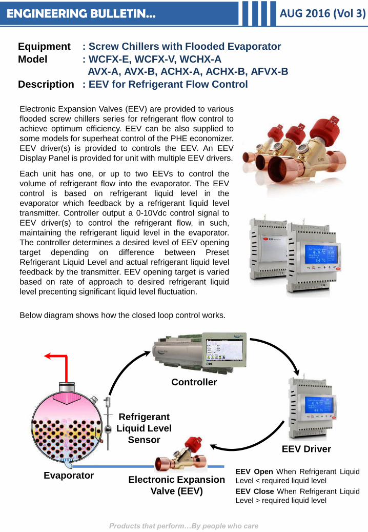
Each unit has one, or up to two EEVs to control the
volume of refrigerant flow into the evaporator. The EEV
control is based on refrigerant liquid level in the
evaporator which feedback by a refrigerant liquid level
transmitter. Controller output a 0-10Vdc control signal to
EEV driver(s) to control the refrigerant flow, in such,
maintaining the refrigerant liquid level in the evaporator.
The controller determines a desired level of EEV opening
target depending on difference between Preset
Refrigerant Liquid Level and actual refrigerant liquid level
feedback by the transmitter. EEV opening target is varied
based on rate of approach to desired refrigerant liquid
level precenting significant liquid level fluctuation.
Below diagram shows how the closed loop control works.
Evaporator
Refrigerant
Liquid Level
Sensor
Electronic Expansion
Valve (EEV)
EEV Driver
Controller
EEV Open When Refrigerant Liquid
Level < required liquid level
EEV Close When Refrigerant Liquid
Level > required liquid level
ENGINEERING BULLETIN… AUG 2016 (Vol 3)
Besides refrigerant flow control during normal operation, the EEV(s) can be also a
preventive action to recover unit from abnormal operation, and to prevent unit from tripping
by alarm. The controller will override the EEV control logic and force EEV in response to
recover unit from abnormal operation, such as below:
a. Low suction pressure
This function prevents the unit from tripping at low evaporator pressure alarm. When
evaporator pressure is approaching low suction pressure cut-off safety setpoint, the
controller will override the capacity control command of the compressor. The compressor
will be forced to hold or unload, and EEV will be forced to open to bring the unit operation
back to normal and safe zone.
b. Low suction-discharge pressure differential
This control function seeks to maintain pressure differential across evaporator and
condenser for proper lubrication and to prevent low suction-discharge pressure differential
alarm. If the controller detects a refrigerant system is operating in low suction-discharge
pressure differential, the SDD control will force the EEV to closes. This starves the
evaporator, which shall lowered the evaporator pressure and subsequently, increases the
pressure differential. When the pressure differential has been built-up and back to safe
zone, SDD control will be off and EEV will regulates according to the unit load demand.
c. Low discharge superheat
Low discharge superheat is an indication of low suction superheat which may increases
risk of liquid flooded back to compressor. When low discharge superheat is detected, EEV
will be forced to close to increases the unit discharge superheat back to safe zone.
Products that perform…By people who care
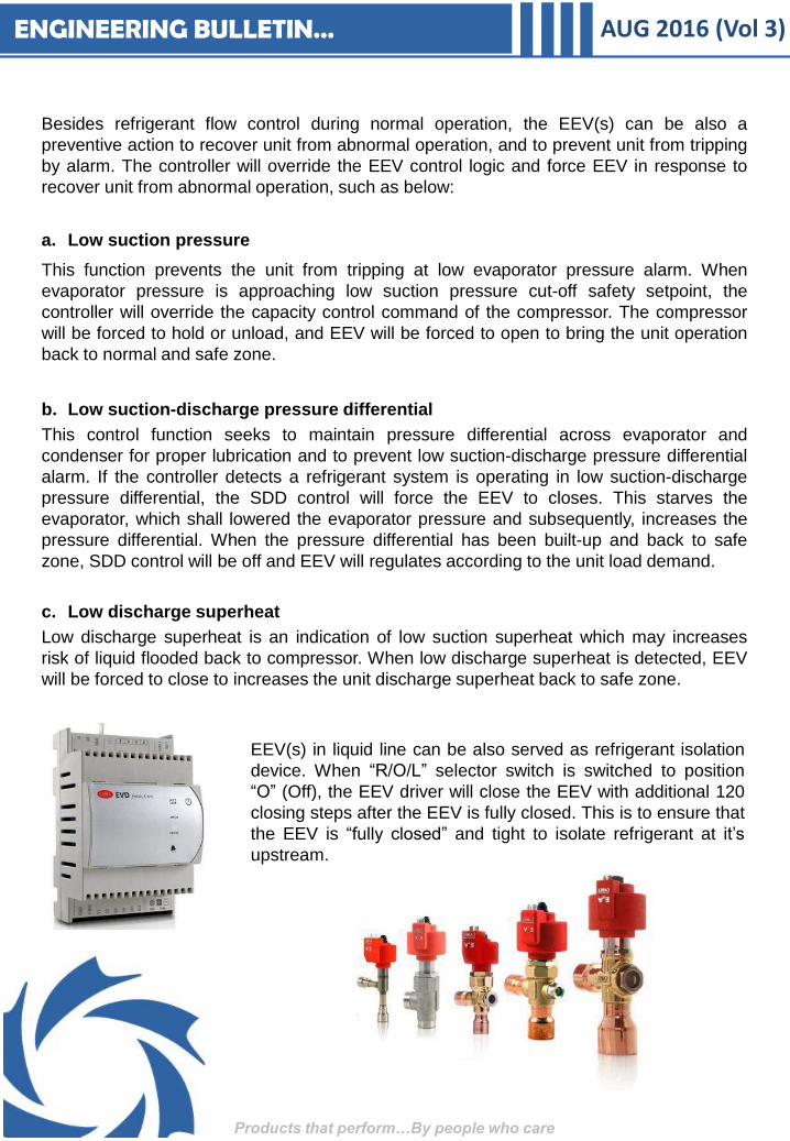
EEV(s) in liquid line can be also served as refrigerant isolation
device. When “R/O/L” selector switch is switched to position
“O” (Off), the EEV driver will close the EEV with additional 120
closing steps after the EEV is fully closed. This is to ensure that
the EEV is “fully closed” and tight to isolate refrigerant at it’s
upstream.
ENGINEERING BULLETIN… AUG 2016 (Vol 3)
Equipment : Chillers
Model : Water-Cooled & Air-Cooled Chillers
Description : Monitored Shipment with “Drop N Tell”
As DB’s slogan says “Products that perform… by people who care.”, DBI has initiated
improvement action to ensure our customer’s interest during unit shipment is protected.
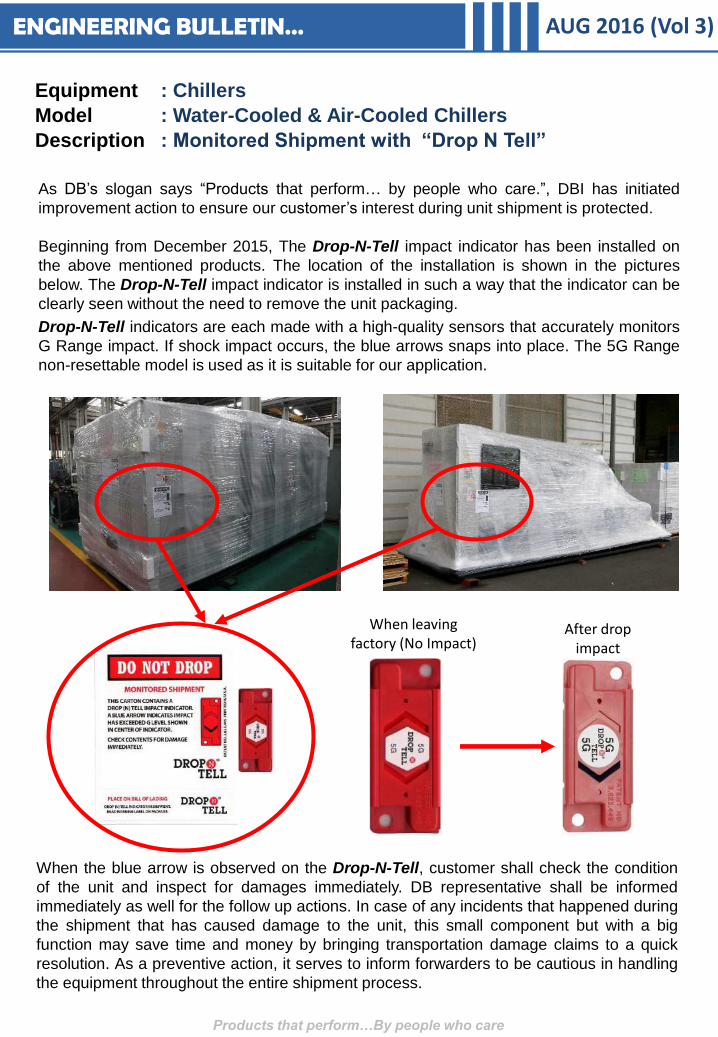
Beginning from December 2015, The Drop-N-Tell impact indicator has been installed on
the above mentioned products. The location of the installation is shown in the pictures
below. The Drop-N-Tell impact indicator is installed in such a way that the indicator can be
clearly seen without the need to remove the unit packaging.
Drop-N-Tell indicators are each made with a high-quality sensors that accurately monitors
G Range impact. If shock impact occurs, the blue arrows snaps into place. The 5G Range
non-resettable model is used as it is suitable for our application.
Products that perform…By people who care
When leaving factory (No Impact)
After drop impact
When the blue arrow is observed on the Drop-N-Tell, customer shall check the condition
of the unit and inspect for damages immediately. DB representative shall be informed
immediately as well for the follow up actions. In case of any incidents that happened during
the shipment that has caused damage to the unit, this small component but with a big
function may save time and money by bringing transportation damage claims to a quick
resolution. As a preventive action, it serves to inform forwarders to be cautious in handling
the equipment throughout the entire shipment process.
ENGINEERING BULLETIN… AUG 2016 (Vol 3)
Equipment : Air Handling Unit (AHU)
Model : CS3, eCS3, sCS3
Description : SPEC – Ashley 2.0
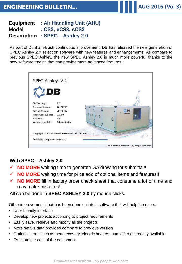
As part of Dunham-Bush continuous improvement, DB has released the new generation of
SPEC Ashley 2.0 selection software with new features and enhancements. As compare to
previous SPEC Ashley, the new SPEC Ashley 2.0 is much more powerful thanks to the
new software engine that can provide more advanced features.
Products that perform…By people who care
With SPEC – Ashley 2.0
NO MORE waiting time to generate GA drawing for submittal!!
NO MORE waiting time for price add of optional items and features!!
NO MORE fill in factory order check sheet that consume a lot of time and
may make mistakes!!
All can be done in SPEC ASHLEY 2.0 by mouse clicks.
Other improvements that has been done on latest software that will help the users:-
• User friendly interface
• Develop new projects according to project requirements
• Easily save, retrieve and modify all the projects
• More details data provided compare to previous version
• Optional items such as heat recovery, electric heaters, humidifier etc readily available
• Estimate the cost of the equipment

ENGINEERING BULLETIN… AUG 2016 (Vol 3)
Unit GA drawing (To-Scale-Drawing) for submission is generated right when unit selection is done.
The GA drawing can be saved in CAD format for easy integration into designer’s drawings. NO MORE WAITING!!
Products that perform…By people who care
Unit check sheet is also generated when the unit selection is done. The same check sheet will be send into factory for manufacturing process.
Improve Efficiency!!
Shorten order processing time!!
ENGINEERING BULLETIN… AUG 2016 (Vol 3)
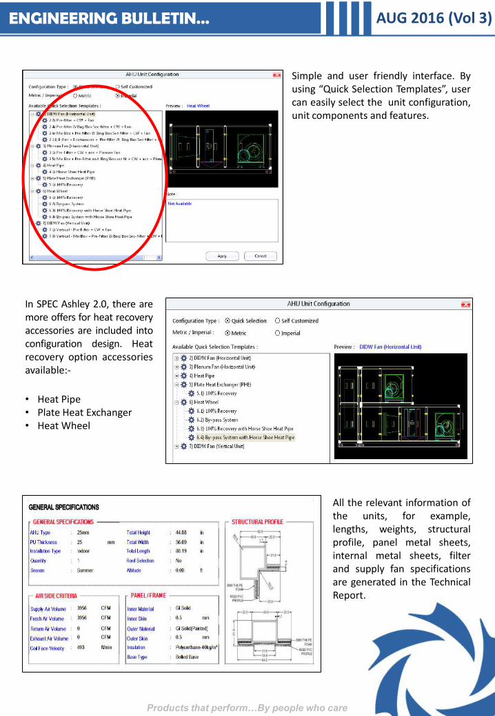
All the relevant information of the units, for example, lengths, weights, structural profile, panel metal sheets, internal metal sheets, filter and supply fan specifications are generated in the Technical Report.
Simple and user friendly interface. By using “Quick Selection Templates”, user can easily select the unit configuration, unit components and features.
Products that perform…By people who care
In SPEC Ashley 2.0, there are more offers for heat recovery accessories are included into configuration design. Heat recovery option accessories available:-
• Heat Pipe • Plate Heat Exchanger • Heat Wheel
AUG 2016 (Vol 3)
Products that perform…By people who care
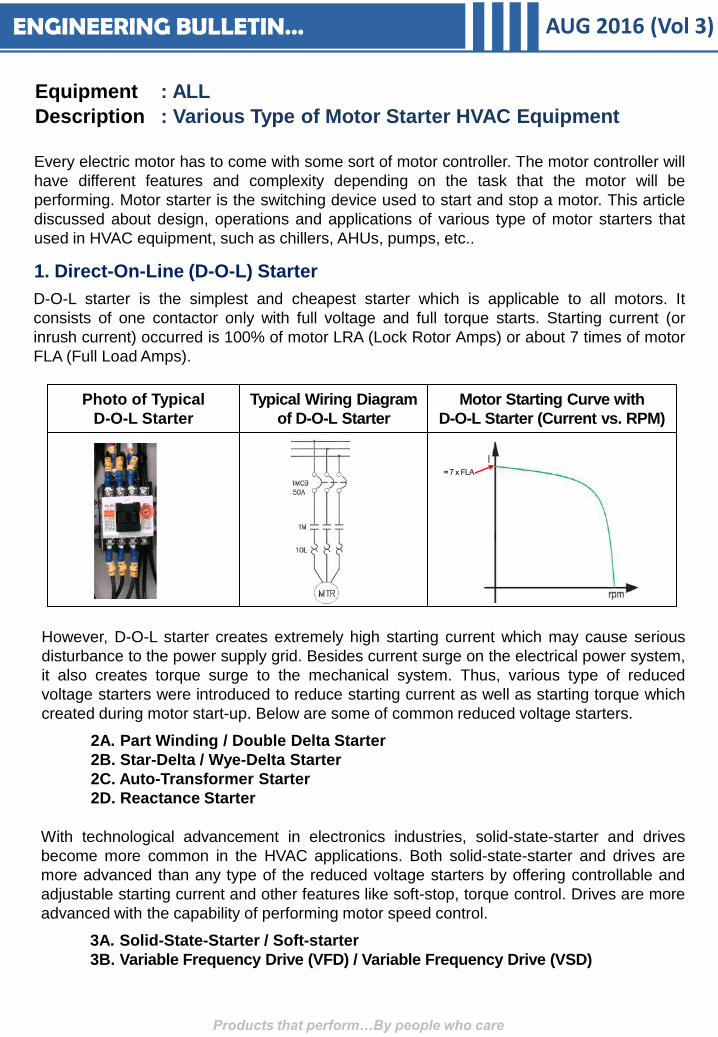
Every electric motor has to come with some sort of motor controller. The motor controller will
have different features and complexity depending on the task that the motor will be
performing. Motor starter is the switching device used to start and stop a motor. This article
discussed about design, operations and applications of various type of motor starters that
used in HVAC equipment, such as chillers, AHUs, pumps, etc..
1. Direct-On-Line (D-O-L) Starter
D-O-L starter is the simplest and cheapest starter which is applicable to all motors. It
consists of one contactor only with full voltage and full torque starts. Starting current (or
inrush current) occurred is 100% of motor LRA (Lock Rotor Amps) or about 7 times of motor
FLA (Full Load Amps).
Photo of Typical
D-O-L Starter
Typical Wiring Diagram
of D-O-L Starter
Motor Starting Curve with
D-O-L Starter (Current vs. RPM)
≈ 7 x FLA
However, D-O-L starter creates extremely high starting current which may cause serious
disturbance to the power supply grid. Besides current surge on the electrical power system,
it also creates torque surge to the mechanical system. Thus, various type of reduced
voltage starters were introduced to reduce starting current as well as starting torque which
created during motor start-up. Below are some of common reduced voltage starters.
2A. Part Winding / Double Delta Starter
2B. Star-Delta / Wye-Delta Starter
2C. Auto-Transformer Starter
2D. Reactance Starter
With technological advancement in electronics industries, solid-state-starter and drives
become more common in the HVAC applications. Both solid-state-starter and drives are
more advanced than any type of the reduced voltage starters by offering controllable and
adjustable starting current and other features like soft-stop, torque control. Drives are more
advanced with the capability of performing motor speed control.
3A. Solid-State-Starter / Soft-starter
3B. Variable Frequency Drive (VFD) / Variable Frequency Drive (VSD)
Equipment : ALL
Description : Various Type of Motor Starter HVAC Equipment
ENGINEERING BULLETIN…

AUG 2016 (Vol 3)
Products that perform…By people who care
2A. Part Winding / Double Delta Starter
Part Winding Starter is only applicable to motors designed with two identical windings in
parallel, wye-wye or Delta-Delta. Dunham-Bush Vertical Screw MSC compressor motors
(127 & 192 series) are designed with two Delta windings, thus, it works together with Double
Delta Starter as the standard reduced voltage starter. Part Winding Starters consist of two
identical contactors. The motor is started up with 50% of full voltage. Thus, the motor starting
current by part winding starter is about 50% of motor LRA, or around 3.5 times of motor FLA.
Photo of typical
Part-Winding Starter
Typical Wiring Diagram
of Part Winding Starter
Motor Starting Curve with
Part Winding Starter
≈ 3.5 x FLA
DOL Starter
Part Winding
Starter
2B. Star-Delta / Wye-Delta (Y-∆) Starter
Y-∆ starter is applicable for motors designed with 6 leads terminal post and suitable for Y-∆
starting. Y-∆ motor with windings connected in Delta (∆) when operating in nominal voltage.
Windings are first connected in wye (Y) configuration during start-up; reconnect to Delta (∆)
connection when motor has comes up to speed.The motor is started up approximately 58%
of full voltage, as motor windings are connected in wye (Y). Thus, the motor starting current
is about 33.3% of motor LRA, or about 2~3 times of motor FLA.
Dunham-Bush Vertical Screw MSC compressor motors (223 series) and new Horizontal
Screw HSC compressors motors are designed with Wye-Delta windings, thus, it works
together with Star-Delta Starter as the standard reduced voltage starter.
Photo of typical
Y-∆ Starter
Typical Wiring Diagram
of Y-∆ Starter
Motor Starting Curve with
Y-∆ Starter
≈ 2.5 x FLA
DOL Starter Star-Delta /
Wye-Delta Starter
ENGINEERING BULLETIN…
AUG 2016 (Vol 3)
Products that perform…By people who care
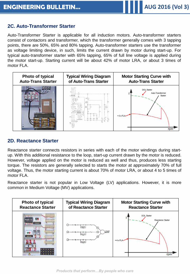
2C. Auto-Transformer Starter
Auto-Transformer Starter is applicable for all induction motors. Auto-transformer starters
consist of contactors and transformer, which the transformer generally comes with 3 tapping
points, there are 50%, 65% and 80% tapping. Auto-transformer starters use the transformer
as voltage limiting device, in such, limits the current drawn by motor during start-up. For
typical auto-transformer starter with 65% tapping, 65% of full line voltage is applied during
the motor start-up. Starting current will be about 42% of motor LRA, or about 3 times of
motor FLA.
Photo of typical
Auto-Trans Starter
Typical Wiring Diagram
of Auto-Trans Starter
Motor Starting Curve with
Auto-Trans Starter
≈ 3 x FLA
DOL Starter
Auto-Transformer
Starter
2D. Reactance Starter
Reactance starter connects resistors in series with each of the motor windings during start-
up. With this additional resistance to the loop, start-up current drawn by the motor is reduced.
However, voltage applied on the motor is reduced as well and thus, produces less starting
torque. The resistors are generally selected to starts the motor at approximately 70% of full
voltage. Thus, the motor starting current is about 70% of motor LRA, or about 4 to 5 times of
motor FLA.
Reactance starter is not popular in Low Voltage (LV) applications. However, it is more
common in Medium Voltage (MV) applications.
Photo of typical
Reactance Starter
Typical Wiring Diagram
of Reactance Starter
Motor Starting Curve with
Reactance Starter
≈ 4 x FLA
DOL Starter
Reactance Starter
ENGINEERING BULLETIN…

AUG 2016 (Vol 3)
Products that perform…By people who care
3A. Solid-State-Starter / Soft-Starter
Solid-State-Starter or Soft-Starter is applicable for all induction motors. Soft-starters use
SCRs (Silicon Controlled Rectifier) or Thyristors to control current drawn by motor during
start-up. Thus, biggest advantages and advancements given by soft-starter compare to any
type of reduced voltage starters are controllable starting current and torque, and smooth
starting to reduced mechanical stress on motor during start-up. 2nd inrush current or
changeover inrush current that occurred in other reduced voltage starters is not applicable to
soft-starters. No changeover inrush current with soft-starter.
In general, motor starting current by soft-starter is around 2 to 4 times of motor FLA
depending on the applications. Besides the built-in motor protection, most of the soft-starters
in today’s market are also having soft-stop as standard feature. This is a good feature
especially when works with water pumps as this helps to prevent water hammering during
pump start and stop, and thus, extend life span of pumps. Soft-starters are usually installed
with bypass contactor, either with built-in bypass or external bypass. Soft-starter will bypass
the line current to bypass contactor after the motor start-up sequence has been completed.
This greatly reduced heat losses at soft-starter.
Photo of typical
Soft-Starter
Typical Wiring Diagram
of Soft-Starter
Motor Starting Curve with
Soft-Starter
≈ 3 x FLA
DOL Starter
Soft-Starter
3B. Variable Frequency Drive (VFD) / Variable Frequency Drive (VSD)
VFD or Drives is so far the known best motor starter which can be used at all type of motors.
Motor starting by VFD is fully controllable and thanks to this smooth starting, the
mechanical stress on motor during start-up is drastically reduced. Motor start-up by VFD
gives the lowest starting current, which is always less than motor FLA. VFD utilized
rectifier bridges, DC capacitor and IGBTs (Insulated-Gate Bipolar Transistor) to visualized
motor speed control and regulation. Thus, VFD is not just a motor starter, but it is also a
motor controller with built-in motor speed control logics, as well as built-in motor protections.
Besides the excellent motor start-up mechanism, most of the VFDs available in today’s
market will also improved displacement power factor of the motor to the level of 0.95 or
above. Thus, besides low starting current which benefits the power grid design, VFDs are
also helping to reduce heat loss at power distribution line.
However, the biggest benefit of VFD applications on HVAC equipment is the impressive
energy savings during partial load operation which is much more efficient than the
mechanical unloading mechanism. The energy saved is dramatic for applications such as
compressors, fans, centrifugal pumps and blower fans, and etc..
ENGINEERING BULLETIN…
AUG 2016 (Vol 3)
Products that perform…By people who care
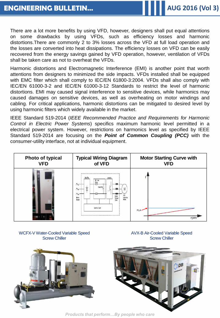
There are a lot more benefits by using VFD, however, designers shall put equal attentions
on some drawbacks by using VFDs, such as efficiency losses and harmonic
distortions.There are commonly 2 to 3% losses across the VFD at full load operation and
the losses are converted into heat dissipations. The efficiency losses on VFD can be easily
recovered from the energy savings gained by VFD operation, however, ventilation of VFDs
shall be taken care as not to overheat the VFDs.
Harmonic distortions and Electromagnetic Interference (EMI) is another point that worth
attentions from designers to minimized the side impacts. VFDs installed shall be equipped
with EMC filter which shall comply to IEC/EN 61800-3:2004. VFDs shall also comply with
IEC/EN 61000-3-2 and IEC/EN 61000-3-12 Standards to restrict the level of harmonic
distortions. EMI may caused signal interference to sensitive devices, while harmonics may
caused damages on sensitive devices, as well as overheating on motor windings and
cabling. For critical applications, harmonic distortions can be mitigated to desired level by
using harmonic filters which widely available in the market.
IEEE Standard 519-2014 (IEEE Recommended Practice and Requirements for Harmonic
Control in Electric Power Systems) specifics maximum harmonic level permitted in a
electrical power system. However, restrictions on harmonics level as specified by IEEE
Standard 519-2014 are focusing on the Point of Common Coupling (PCC) with the
consumer-utility interface, not at individual equipment.
Photo of typical
VFD
Typical Wiring Diagram
of VFD
Motor Starting Curve with
VFD
FLA
WCFX-V Water-Cooled Variable Speed
Screw Chiller
AVX-B Air-Cooled Variable Speed
Screw Chiller
ENGINEERING BULLETIN…
AUG 2016 (Vol 3)
Products that perform…By people who care
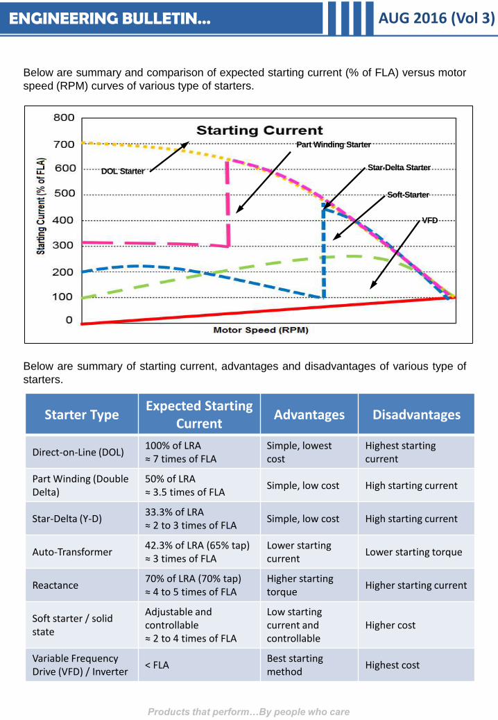
Below are summary of starting current, advantages and disadvantages of various type of
starters.
Below are summary and comparison of expected starting current (% of FLA) versus motor
speed (RPM) curves of various type of starters.
DOL Starter
Part Winding Starter
Star-Delta Starter
Soft-Starter
VFD
Starter Type Expected Starting
Current Advantages Disadvantages
Direct-on-Line (DOL) 100% of LRA ≈ 7 times of FLA
Simple, lowest cost
Highest starting current
Part Winding (Double Delta)
50% of LRA ≈ 3.5 times of FLA
Simple, low cost High starting current
Star-Delta (Y-D) 33.3% of LRA ≈ 2 to 3 times of FLA
Simple, low cost High starting current
Auto-Transformer 42.3% of LRA (65% tap) ≈ 3 times of FLA
Lower starting current
Lower starting torque
Reactance 70% of LRA (70% tap) ≈ 4 to 5 times of FLA
Higher starting torque
Higher starting current
Soft starter / solid state
Adjustable and controllable ≈ 2 to 4 times of FLA
Low starting current and controllable
Higher cost
Variable Frequency Drive (VFD) / Inverter
< FLA Best starting method
Highest cost
ENGINEERING BULLETIN…

APPLICATION BULLETIN… AUG 2016 (Vol 3)
Equipment : Air Handling Unit (AHU)
Model : CS3, eCS3, sCS3
Description : AHU For Outdoor Installation
Dunham Bush Air Handling Unit (AHU) CS3, eC3 and sCS3 Series are designed for indoor
installation. The AHUs construction design can be configured for draw thru or blow thru
application, with blower arrangement in either horizontal, vertical, or footprint-saving
arrangements. Site-assembly option is available with unit delivered to site in sections,
which is very helpful for renovation and retrofit jobs. The sections can pass through
standard doorways, and fitted into cargo lifts.
Products that perform…By people who care
CS3 and sCS3 series AHUs will be good for outdoor installation with add-on accessories
and features as below.
Pitch Roof Powder Coated Casing &
Base structure
Recommended
in One Section
Stainless Steel
Fasteners
APPLICATION BULLETIN… AUG 2016 (Vol 3)
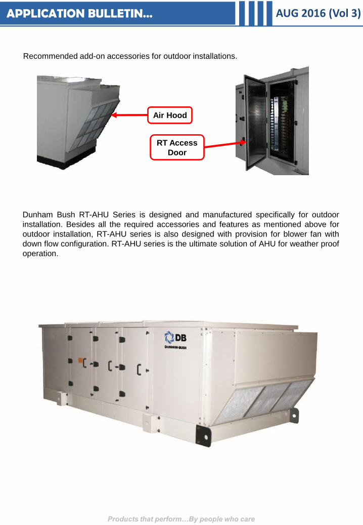
RT Access
Door
Air Hood
Dunham Bush RT-AHU Series is designed and manufactured specifically for outdoor
installation. Besides all the required accessories and features as mentioned above for
outdoor installation, RT-AHU series is also designed with provision for blower fan with
down flow configuration. RT-AHU series is the ultimate solution of AHU for weather proof
operation.
Products that perform…By people who care
Recommended add-on accessories for outdoor installations.

APPLICATION BULLETIN… AUG 2016 (Vol 3)
Equipment : Air-Cooled Chillers
Description : Adiabatic Air Inlet Cooling System
Global warming and increased in climate temperature bring more and more challenges to
designers and operators to design and operate a HVAC system efficiently. Increasing in
ambient temperature gives direct impact to air-cooled chiller systems as the chillers’
efficiency are very much depending on the ambient dry bulb temperature. Hotter summer
days will give additional stress to the air-cooled chillers operation.
Products that perform…By people who care
The phenomena above increases the heat rejected by the chiller up to 40% or even more
depending on design and operation. By reducing the on-coil air dry bulb temperature and
keeping the coil clean, it is possible to realized peak savings to be as much as 30-40% with
annual savings of 15-25% depending on the location, application and operational patterns
of the system.
Adiabatic Air Inlet Cooling or Evaporative
Cooling System is a technology introduced to
work together with an air-cooled chiller, which
to improve chiller efficiency by lowering the
on-coil air dry bulb temperature at air-cooled
condensers via the evaporative cooling cycle.
See Figure 1 on the left which explained the
working principle of this air inlet cooling
system. Figure 2 below shows the potential
reduction on air intake dry bulb temperature
across the evaporative cooling cycle in
relation to relative humidity of ambient air.
Discharged
Air
Hot Air
Cooled
Evaporative Air
Figure 1
Figure 2
Hot Climate
Temperate Climate
How the system works?
The air inlet cooling system is activated
by an external command, either by
ambient temperature, or the chiller’s
head pressure. When the system is
activated and water is sprayed around
the chiller, below processes will take
part to improve the chiller operation.
A. Water evaporation in air reduces the air
temperature significantly thanks to the
evaporative cooling effect.
B. Water drops not evaporated in air will
then deposit on the fins of the coils and
water starts to evaporate into the air
streaming through the coils. This
evaporation is forced by the so-called
mass convection.
APPLICATION BULLETIN… AUG 2016 (Vol 3)
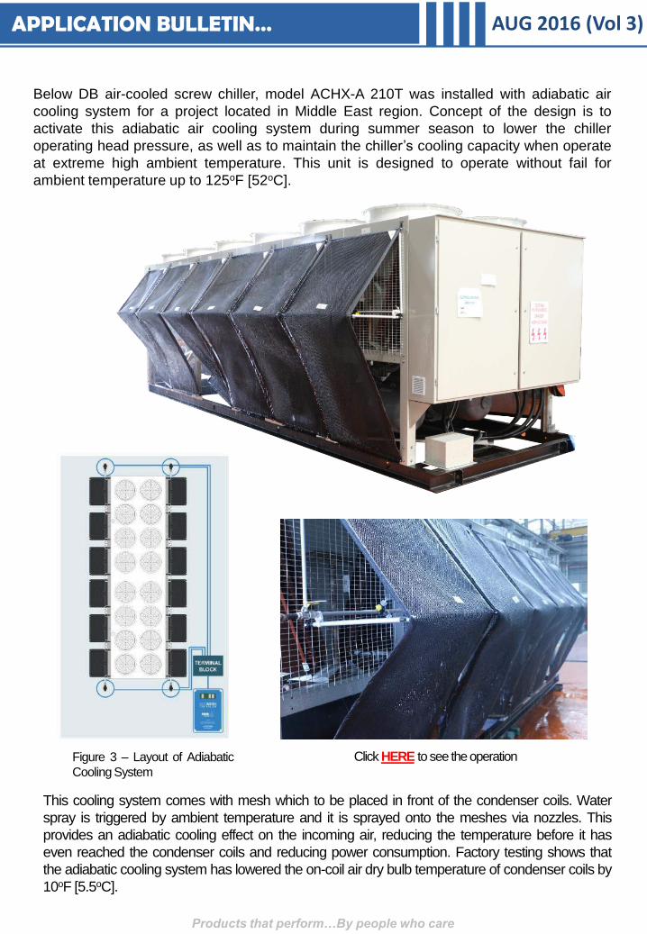
Below DB air-cooled screw chiller, model ACHX-A 210T was installed with adiabatic air
cooling system for a project located in Middle East region. Concept of the design is to
activate this adiabatic air cooling system during summer season to lower the chiller
operating head pressure, as well as to maintain the chiller’s cooling capacity when operate
at extreme high ambient temperature. This unit is designed to operate without fail for
ambient temperature up to 125oF [52oC].
Products that perform…By people who care
Click HERE to see the operation
This cooling system comes with mesh which to be placed in front of the condenser coils. Water
spray is triggered by ambient temperature and it is sprayed onto the meshes via nozzles. This
provides an adiabatic cooling effect on the incoming air, reducing the temperature before it has
even reached the condenser coils and reducing power consumption. Factory testing shows that
the adiabatic cooling system has lowered the on-coil air dry bulb temperature of condenser coils by
10oF [5.5oC].
Figure 3 – Layout of Adiabatic
Cooling System

SERVICE BULLETIN… AUG 2016 (Vol 3)
Equipment : All Chillers
Model : Chillers with Built-in Controller
Description : Disconnected Controller Power Supply Prior To
Shipment
DB Product Quality team was aware of increasingly controller failure prior to testing &
commissioning of chiller, since year 2015. After careful studies and investigations of
various departments, it was concluded that the root cause of such failure was improper
handling at site, such as, chiller’s base was used as “Earthing” of welding machine when
site installers were setting up inter-connection piping from chiller to system water piping.
Welding machine draws high current when it was in operation. Power supply of the
controllers are “Earth” to the electrical enclosure. Thus, the above wrong practice may
cause high voltage spike to the controller, and thus, damage the controller.
In order to protect the user’s benefits, Service Bulletin SB002/16 has been issued at Mid
March 2016 to enforced practice to disconnect all power supply connectors from controllers
prior to unit shipment.
Products that perform…By people who care
The circled connectors as shown in the pictures above shall be supplied in disconnected
form as a preventive action to avoid any damage to the electronic parts before Testing &
Commissioning. Each connector is tagged and its matching corresponding connection
point on the controller body is also tagged. These connectors are to be re-connected to the
controller as per tag during Testing & Commissioning.
CASE STUDY #1… AUG 2016 (Vol 3)
Products that perform…By people who care
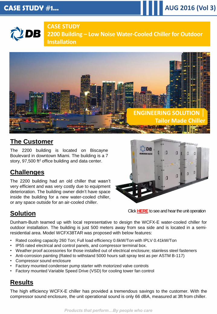
The Customer
The 2200 building is located on Biscayne
Boulevard in downtown Miami. The building is a 7
story, 97,500 ft2 office building and data center.
CASE STUDY 2200 Building – Low Noise Water-Cooled Chiller for Outdoor Installation
Challenges
The 2200 building had an old chiller that wasn’t
very efficient and was very costly due to equipment
deterioration. The building owner didn’t have space
inside the building for a new water-cooled chiller,
or any space outside for an air-cooled chiller.
Solution
Dunham-Bush teamed up with local representative to design the WCFX-E water-cooled chiller for
outdoor installation. The building is just 500 meters away from sea side and is located in a semi-
residential area. Model WCFX38TAR was proposed with below features:
• Rated cooling capacity 260 Ton; Full load efficiency 0.6kW/Ton with IPLV 0.41kW/Ton
• IP55 rated electrical and control panels, and compressor terminal box.
• Weather proof accessories for those installed out of electrical enclosure; stainless steel fasteners
• Anti-corrosion painting (Rated to withstand 5000 hours salt spray test as per ASTM B-117)
• Compressor sound enclosure
• Factory mounted condenser pump starter with motorized valve controls
• Factory mounted Variable Speed Drive (VSD) for cooling tower fan control
Results
The high efficiency WCFX-E chiller has provided a tremendous savings to the customer. With the
compressor sound enclosure, the unit operational sound is only 66 dBA, measured at 3ft from chiller.
ENGINEERING SOLUTION │ Tailor Made Chiller
Click HERE to see and hear the unit operation

CASE STUDY #2… AUG 2016 (Vol 3)
ENGINEERING SOLUTION │ Low Temp. Industrial Chiller
The Customer
GlaxoSmithKline plc (GSK) is one of the world's largest pharmaceutical company,
and was the first global healthcare company to establish a presence in Singapore.
GSK is a science-led global healthcare company who research and develop a broad
range of innovative products in three primary areas of pharmaceuticals, vaccines and
consumer healthcare sciences industry. GSK Global Manufacturing Plant located at
Jurong, Singapore manufactures active pharmaceutical ingredients (APIs) used in a
variety of GSK prescription medicines.
CASE STUDY GSK – Low Temperature Process Cooling Chiller
Challenges
The process cooling fluid was supplied by two number of 20 years old chillers, each with rated
capacity 120Ton. Performance of the chillers were de-rated a lot over the time, and was operated at
efficiency of 2.2kW/Ton. Chillers were operated with high power consumption, as well as huge
maintenance cost. The client plan to replace two chillers with one bigger chiller for best ROI (return
of investment), with below design requirements.
i. Capacity = 245TR
ii. Fluid Type = 45% EG (Mono-Ethylene Glycol)
iii. Entering / Leaving Fluid Temp. = 6.8/-5.8oF [-14/-21oC]
iv. Pressure vessels to be certified by MOM (Ministry of Man Power, Singapore)
v. Unit to be installed at outdoor, with shelter above the unit to avoid direct sunlight and rain water
vi. Multiple compressors for redundancy
vii. 24/7 continuous operation
viii. Full load efficiency to be less than 1.9kW/Ton
Products that perform…By people who care
CASE STUDY #2… AUG 2016 (Vol 3)
Products that perform…By people who care
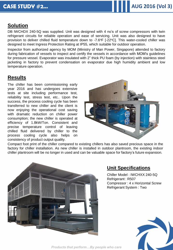
Solution DB IWCHDX 240-5Q was supplied. Unit was designed with 4 no’s of screw compressors with twin
refrigerant circuits for reliable operation and ease of servicing. Unit was also designed to have
provision to deliver chilled fluid temperature down to -7.6oF [-22oC]. This water-cooled chiller was
designed to meet Ingress Protection Rating at IP55, which suitable for outdoor operation.
Inspector from authorized agency by MOM (Ministry of Man Power, Singapore) attended to factory
during fabrication of vessels to inspect and certify the vessels in accordance with MOM’s guidelines
for pressure vessel. Evaporator was insulated with 2” thick PU foam (by injection) with stainless steel
jacketing in factory to prevent condensation on evaporator due high humidity ambient and low
temperature operation.
Results
The chiller has been commissioning early
year 2016 and has undergoes extensive
tests at site including performance test,
reliability test, stress test, etc.. Upon the
success, the process cooling cycle has been
transferred to new chiller and the client is
now enjoying the operational cost saving
with dramatic reduction on chiller power
consumption; the new chiller is operated at
efficiency of 1.8kW/Ton. Consistent and
precise temperature control of leaving
chilled fluid delivered by chiller to the
process cooling cycle also helps on
consistency of product output quality.
Unit Specifications
Chiller Model : IWCHXX 240-5Q
Refrigerant : R507
Compressor : 4 x Horizontal Screw
Refrigerant System : Two
Compact foot print of the chiller compared to existing chillers has also saved precious space in the
factory for chiller installation. As new chiller is installed in outdoor plantroom, the existing indoor
chiller plantroom will be no longer in used and can be valuable space for factory’s future expansion.
CASE STUDY #3… AUG 2016 (Vol 3)
Products that perform…By people who care
ENGINEERING SOLUTION │ High Efficiency WCFX-V Chiller
The Customer
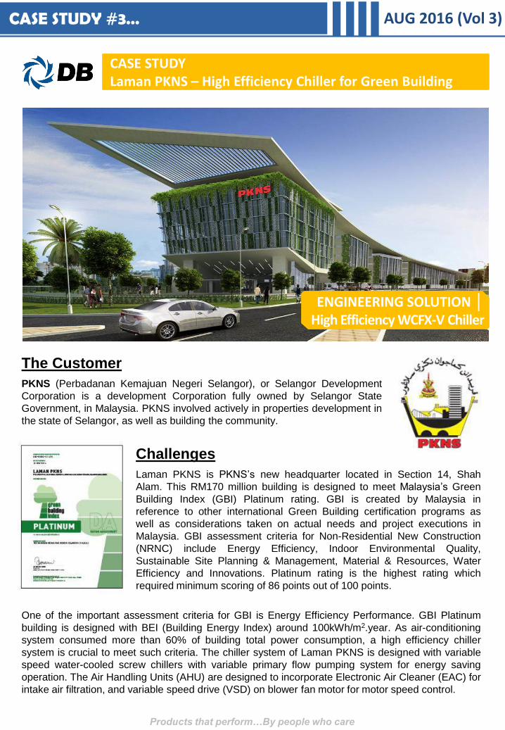
PKNS (Perbadanan Kemajuan Negeri Selangor), or Selangor Development
Corporation is a development Corporation fully owned by Selangor State
Government, in Malaysia. PKNS involved actively in properties development in
the state of Selangor, as well as building the community.
CASE STUDY Laman PKNS – High Efficiency Chiller for Green Building
Challenges
Laman PKNS is PKNS’s new headquarter located in Section 14, Shah
Alam. This RM170 million building is designed to meet Malaysia’s Green
Building Index (GBI) Platinum rating. GBI is created by Malaysia in
reference to other international Green Building certification programs as
well as considerations taken on actual needs and project executions in
Malaysia. GBI assessment criteria for Non-Residential New Construction
(NRNC) include Energy Efficiency, Indoor Environmental Quality,
Sustainable Site Planning & Management, Material & Resources, Water
Efficiency and Innovations. Platinum rating is the highest rating which
required minimum scoring of 86 points out of 100 points.
One of the important assessment criteria for GBI is Energy Efficiency Performance. GBI Platinum
building is designed with BEI (Building Energy Index) around 100kWh/m2.year. As air-conditioning
system consumed more than 60% of building total power consumption, a high efficiency chiller
system is crucial to meet such criteria. The chiller system of Laman PKNS is designed with variable
speed water-cooled screw chillers with variable primary flow pumping system for energy saving
operation. The Air Handling Units (AHU) are designed to incorporate Electronic Air Cleaner (EAC) for
intake air filtration, and variable speed drive (VSD) on blower fan motor for motor speed control.

CASE STUDY #3… AUG 2016 (Vol 3)
Products that perform…By people who care
Results
Laman PKNS has successfully pass the GBI’s Design Assessment and obtained the GBI Platinum
Certification. Achievement of Laman PKNS is remarkable as this is one of the very few buildings that
can achieve GBI Platinum rating in Malaysia.
Solution Below equipment was supplied:-
3 x 400TR Variable Speed Water-Cooled Screw
Chiller - WCFX-V 50T
21 x AHU - CS3 series
The 400TR WCFX-V 50T chiller is designed with
supreme efficiency with full load efficiency 0.572
kW/Ton [COP 6.15] rated at Malaysia standard
design conditions. The chiller operates even more
efficient at partial loading condition with part load
efficiency up to 0.426 kW/Ton [COP 8.26].
The AHUs (CS3 series) are furnished with factory
installed Electronic Air Cleaner which served as
pre- and secondary filter of the unit. This feature
also helps to score 1 point under IN1 (Innovation).
Blower motors are also furnished with factory
supplied variable speed drive (VSD) for speed
control to maximized the operation savings of
AHUs.
This high efficiency performance assured the GBI scoring in assessment criteria EE5 (Advanced EE
Performance – BEI) which can contribute up to 15 points. The green refrigerant R134a with zero
ODP (Ozone Depletion Potential) used in WCFX-V chiller is also helps to score 1 point under MR6
(Green Products – Refrigerant & Clean Agent). Vessels of the chillers are designed to obtained
Malaysia JKKP approval (JKKP is equivalent to DOSH in English). JKKP approved vessels are
having more stringent requirements than ASME coded vessels.
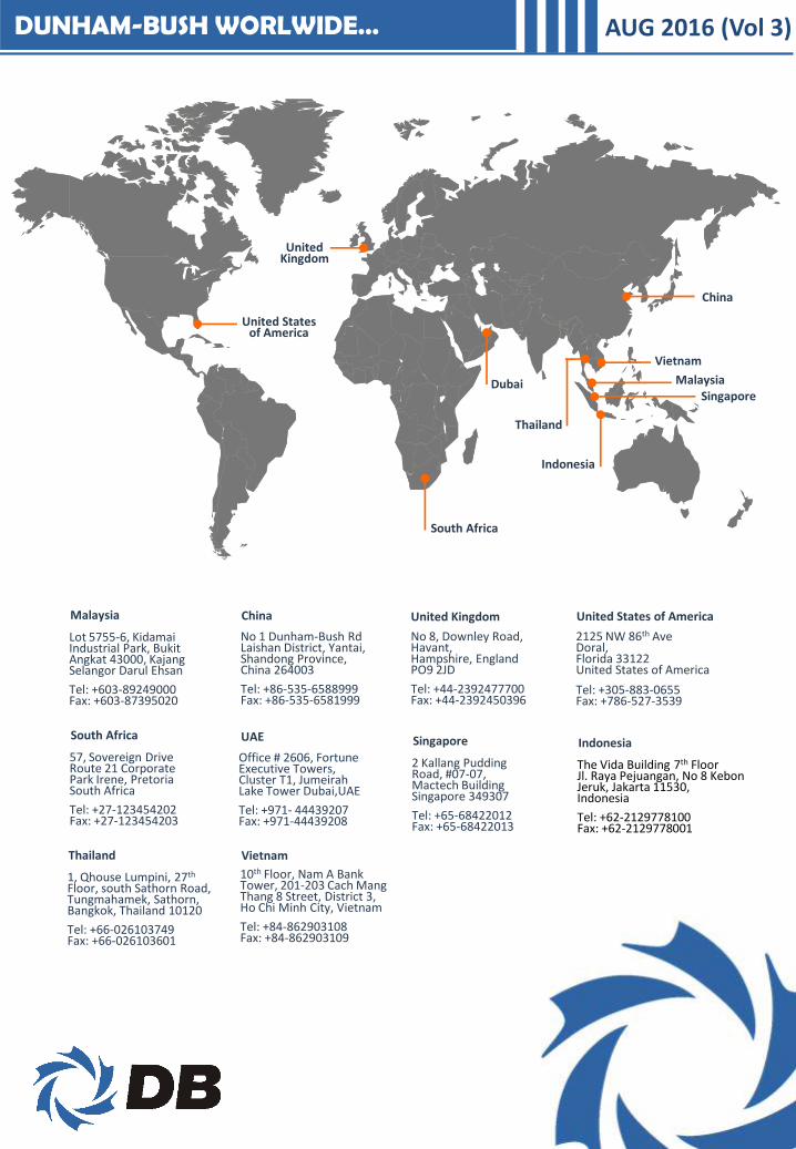
DUNHAM-BUSH WORLWIDE…
Singapore Malaysia
China
South Africa
Dubai
Indonesia
Vietnam
Thailand
United Kingdom
Malaysia
Lot 5755-6, Kidamai Industrial Park, Bukit Angkat 43000, Kajang Selangor Darul Ehsan
Tel: +603-89249000 Fax: +603-87395020
China
No 1 Dunham-Bush Rd Laishan District, Yantai, Shandong Province, China 264003
Tel: +86-535-6588999 Fax: +86-535-6581999
United Kingdom
No 8, Downley Road, Havant, Hampshire, England PO9 2JD
Tel: +44-2392477700 Fax: +44-2392450396
United States of America
2125 NW 86th Ave Doral, Florida 33122 United States of America
Tel: +305-883-0655 Fax: +786-527-3539
South Africa
57, Sovereign Drive Route 21 Corporate Park Irene, Pretoria South Africa
Tel: +27-123454202 Fax: +27-123454203
Singapore
2 Kallang Pudding Road, #07-07, Mactech Building Singapore 349307
Tel: +65-68422012 Fax: +65-68422013
Indonesia
Vietnam
10th Floor, Nam A Bank Tower, 201-203 Cach Mang Thang 8 Street, District 3, Ho Chi Minh City, Vietnam
Tel: +84-862903108 Fax: +84-862903109
Thailand
1, Qhouse Lumpini, 27th Floor, south Sathorn Road, Tungmahamek, Sathorn, Bangkok, Thailand 10120
Tel: +66-026103749 Fax: +66-026103601
AUG 2016 (Vol 3)
The Vida Building 7th Floor Jl. Raya Pejuangan, No 8 Kebon Jeruk, Jakarta 11530, Indonesia
Tel: +62-2129778100 Fax: +62-2129778001
UAE
Office # 2606, Fortune Executive Towers, Cluster T1, Jumeirah Lake Tower Dubai,UAE
Tel: +971- 44439207 Fax: +971-44439208
United States of America