Embed Size (px)
Citation preview
l
I
l " I
l
J .. I
I "
JOURNAL OF RESEARCH of the National Bureau of Standards-C. Engineering a nd Instrumentation Vol. 660 , No.4, Odober- December 1962
A Dual Centrifuge for Generating Low-Frequency Sinusoidal Accelerations
R. O . Smith, E. A. Willis, and 1. S. Bilten
(July 10, 1962)
Thi s p aper describes a n ex perimental " dual centrifuge" in \\'hich an accelerometer being cril ib nLtcd is carried aro und a circula r path in a horizontal p lane. If the instrument is constrained to have nonrotaLional motion, such as is provided by a parallel li nk device, sinusoidal excitatio n along its se nsitive (horizontal) axis is obtained. The excitation obtainable is eq ui valent to linear exc itat ion but at unusually low frequency and large displ acement. For example, a machine has been built \I"h ich has a frequency range from 0.5 to 30 cycles per seco nd , [1 displaceme nt (zero to peak) up to 12 inch es, and develops an accelerat ion ampli t ud e, usefu l for cali bration, lip 10 ] 00 grav it.v at 10 cycles per second and above.
1. Introduction
Because of' titc wide usc or l o\\'-rrcqucn("~' aecd('/"oilleters there is a lIeed Jor a culibration S\'StCIll tailored to the requirelHents of these inst rUlilcnts. This necessil y has led to the consici erat ion or several methods of gell erating the required low-r requcncy accelerations . At low Jrequencies most s~'stems suffer from one or more limitations , such as poor waveform, rest ricted amplitude, or excessive superimposed vibration .
The several syste ills ror obtainillg low-frequenc~r sinusoidal calibration have been reviewed , which ma~be class ified as (1) electrodynamic , (2) trans ien t, or (3) meehan ical shakers.
The electrodynamic shaker is undoubtedly the most useful calibrator for laborator y use. Ho \·vever, it usuall~- sutl'ers from insuffi cient amplitud e at low frequen cies. A typical example of a ]ow-frequenc? electrod~-namic shaker has a frcquenc~r range of 0.35 to 500 cis but provides a maximum displacement of only 2 in. (double amplitude), whereas about 20 in. displacement is r equired to develop 1 g at 1 cis.
Transient shakers usually take t he Jorm of a cantilever spring upon whose free end the instrument under test is fixed. They suffer from the fact that the excitation is transien t, so that it is diffieult to correlate excitation amplitude with response. In addition each shaker is usually restri cted to a single frequency and several shakers are required to cover an~- appreciable range.
The mechanical shakers reviewed may be subdivided into three classifications: (1) four-bar linkages , (2) inertial shakers, and (3) rotary calibrators. Four-bar linkages, e.g., scotch yokes and slidercrank mechanisms, cannot generate a truly sinusoidal test motion because of the varying etl'ective moment of inertia. In order to get the requisite stiffness in the reciprocating parts it. is required that a relativel~large mass be sub jected to the test motion so that the sinusoidally varying inertial forces are necessarily large. H the test motion is to be nearly sinusoidal it is required that the angular velocities of the rotating parts be nearly uniform and it will therefore be required that the rotating members have
a high moment of inertia, and a bulk~-, ma;;::SlYC device results.
All in erLial sllaker suitable for calibnllioll purposes has been designed by the Engineering Mechallics Section oJ the Bureau [1] I which consists of a springJllass dri ven by an ecceillric weig ilt. lls freq uency range is 20 to llO cis . Ill erlilll s hakers oJ lower frequen cy arc rarely used for calibmlion beclLUse of poor wave l'orm.
A rotary dyn amic calibrator which uses the earth's field for excitation has been devised by vVildhack and Smith [2]. This device is limited in acceleration ltlllplitucle to a maximum or 1 g at flU frequencies. It is presently in use by the :Mechanicnl In strumenls Section of th e Bureau over the frequell cy range 1 to 30 cis.
The dual cen tri fuge, which uses its own een trifugal field for exeitatioll , was described b~' IiVoolard in 1939 [3]. It consis ls essentially or a small turntable mo u n ted on a large one, each turning in a horizontal plan e . Th e instrument und er les t is mounted on the small table. When t he turn tables lut ve constant angular veloci ties t he seismic mass o r the accelerometer responds to a sinu soidally var~-ing componen t oJ the cen tri rugal force field genen1teci by the rotation of the large table. Woolard published an equation showing t he acceleration amplitude in terms of angular velocities, original displacement, and relative displacement of the seismic mass, but did not publish a complete mathematical analysis of the response. However, he did point out that when the small table turns backwards so that it lms zero absolute rotation, the accelerometer is submitted to sinusoidal acceleration which may be oJ huge amplitude. This is the practieally importan t feature of the dual centrifuge and on e that has been generally overlooked.
The following discussion , which describes a mechanical configuration similar to Woolard's design, and develops t he equation of motion of the seismic mass, shows tbe dual centrifuge to be a useful tool Jor dynamic calibration , particularly when a large amplitude is required at low frequencies.
1 Fig ures in brac kets indicate tho literature rererences at the end o( th is paper.
357
2. Analysis of the Response of a Linear ' I-Degree of Freedom Seismic Accelerometer to General Plane Motion Excitation
Although the conclusion of this paper is that tl;e useful form of t he dual centrifuge IS that one In
which the small table has zero absolu te rotation, a general an alysis of the motion without this limi tation is instructive.
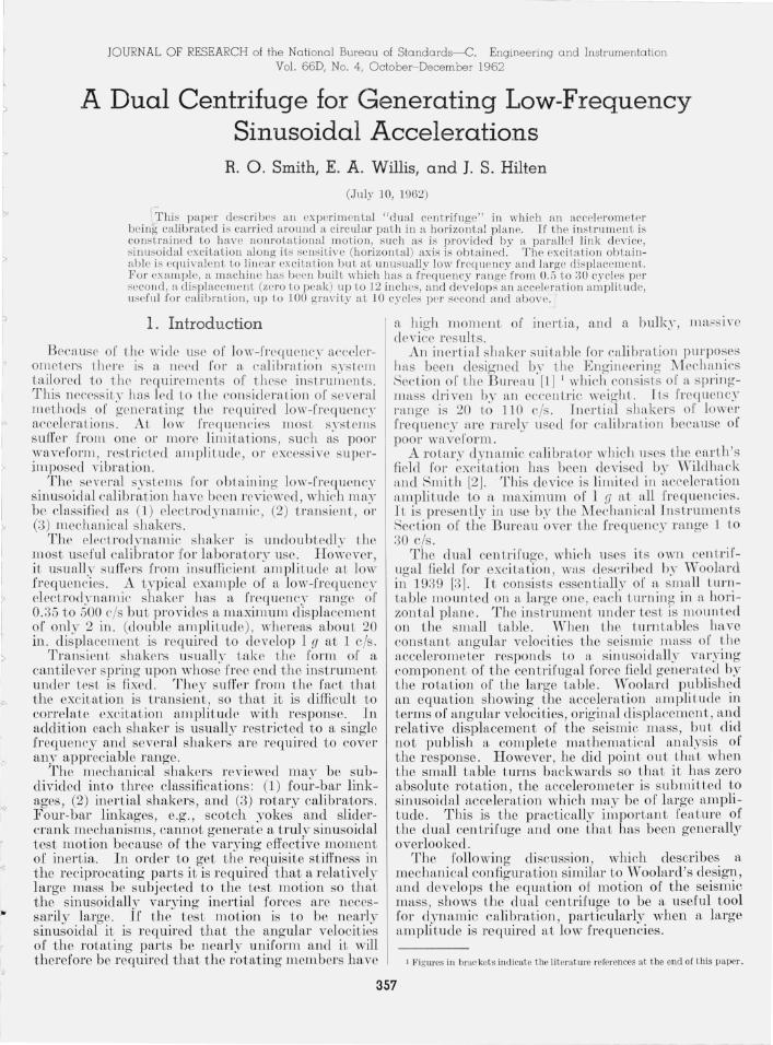
In the general case, the housing of t he instrument under test will have motion of 3 degrees of freedom , i.e. , two o[ tran slation and one of rotation . The physical si tuation .is shown in figure 1. The laI:ge turn table t urn s wIth an a bsolute angular velocIty Wo abo ut its center O. The small table ro tates about point p with co nstant absohl te angular velocity WI!)
and an angular velocity Q= wp-wo relativ:e. to the large table. The point 0 is chosen as the.on gm .or fI plftn e nonrotating coordinate system, wIth. posItIve directions chosen according to usual con ven tIOn . Let the radius from 0 to p be R o. In general , the test position p' of the seismic m ass. m \~ill not eoincid.e with p. If a-b represents the clirectlOn of the sen sItive axis, then p' is located an amount cl from p, perpendicular to a-b, and an amount e . paral~el .to a-b. R esponse of the instrument ~on sJ sts of. dl~placement S along a-b and the equatIOn of motIon IS therefore in terms of S.
Th e followin g assumptions apply to the analysis: (J) Plan e horizon tal motion, (2) Point 0 is fixed , (3) Ho, wo, and Wp are constant,· (4 ) The instrum en t has no transverse response , (5) The instrument is a linear I-degree of freedom
system, (6) Accelerometer dampin g.is viscous. . R eferring to figure 1, It WIll be seen that If t he
seismic mass m is constrain ed to motion along the axis a-b the mo tion of th e mass may be described by the following coordinate equations in which s,
b
RO f Wo
------ ----- - ------- - --- --x
------ .....
FIGURE 1. Schematic diagram of the d1wl centrifuge.
s, and s are relative to the in s trument case:
x= R o cos wot-d sin wpt + (e + s)cos wpt
y = R o sin wot + cl cos wpt+ (e + s)sin wpt·
(1)
(2)
D ouble differentiation shows that the coordinate equations which describe the accelen.tion of mare:
X= - R o w5 cos wot + cl w; sin wpt - (e+s)w~ cos wpt
Y= - Row~ sin wot-dw~ cos w"t - (e+s)w; sin wpt
+ 2sw p cos wpf + s sin wpt·
(3)
(4)
The acceleration along the axis a-b to wbich. the mass m is subj ected is the sum of the projectIOns of these coordinate compon en ts along a-b, I.e. , acceleration =x cos wpt+ y sin w,)t or acceleration =s- (e + s) w;)-Row~ cos Qt.
So that t he equation oJ motion ntay be derived:
ms + cs + ks=mRow~ cos Qt + m (e+s)w;. (5)
If wn=~! and p = c/c cri tical when c critical
= 2.Jmk, this equation can be reduced to:
The solution of eq (6) is:
The steady state portion of eq (7) reduces to:
s RoW5 cos (Qt - ¢i) ew~
[( w~-w~- Q2)2+4p2w,~ Q 2F /2+ w~- w~ (8)
in which
tan ct>
It should be noted that in the form of the dual centrifuge in which wp = O, . i .e., ~= - Wo, ,eq . (7) takes a form almost IdentlCal with the Jmmhar equation lor a spring-mass accelerometer subject to sinusoidal linear motion
s=Ae-wnt(]:'+~lJ'- l ) + B e-w,t(p- ,1p2_ I)
R ow5[(w;_ Q2) cos Qt + 2pwn Q sin Qt l + ( w;- Q2)2+4p2w~ Q2 (9)
In which Q == - woo
358
I
1
, ~
I
I
Th e sleady sta te portion nmy be wri tte ll ;.
(10)
From the foregoing i t is evident that 1'01' LllC special case in which the instrument h flS only tmnslation al motion, tbe motion of m is si Il1ple si n usoidal and hence ma~T be directly compared with data using fln electrodyn amic shaker . In f flCL, for fl given instrument, data from the double centrifuge and t ll e electrodynamic shflker may be used together to construct a single response curve (see figs . 7, 8, and 9) .
3. Limitations of the Dual Centrifuge
Consid emLion oC the r esponse of a lin ear, single degree of freedom system to Lhe general Cflse of the dUfll ce ll trifuge in wltich tll e flng ulal' velocity oC the li ttle table is independent oC Lhat of t he large table indica.tes that tb is form of the equipm.ent is not attractive for flccurate calibmtion . Examina.tion or t be response equation (7) shows that t he magnitude of the transient at any instant depend s upon W p as well as upon the instrument natuml frequency W n
2
and the in strume ll t dflmping p. 'When p2+wl~ < 1, w"
2
the transient is oscillatory. At p2+~-= I , the . w~
2
transien t is critically damped an d w:l en p2+~? > 1, w"
it is over-damped. This latter suggests th~t at
very lilrge values o f the ratio Wp the decay of the W n
transient ma.y be so slow as to prevent the pmcticaJ attain men t of Lhe steady stflte condition. Moreover , examin ation of t he s Leady bias portion of eq (8) shows thaL , even aCter steady state conditions h ave been attained , there is a rflnge of Wp over w hich t he seismic mass will be frozen agaiJ] st Lhe instrument stops , the frequency range over wlJich this coneli tion will exist depending on t he magnitude of the o A'set e in figure 1.·
'\Vi thout further evalmttioll of either of the above condi t ions, a decisive considemtio n is found by examin a tion of t he periodic portion of eq (8) which discloses t hat t lte condition of r esonance will be realized wllClleVel' wp+ rl = wn , so t hat fl frequen cyresponse curve of the instrument can be drawn only if the condition wp= constant, i.e. , wo + rl = constan t , can be m ain tain ed. Since t he frequency-response curve is t be obj ective of sinusoidal input testing, this limitation appear s to make use of the general case of the du al centrifuge unprofitable. Accordingly the test machine which will be described in the next secLion was made to operate with wp = O so that eq (10) is applicable.
It is to be noted that, since a tr ansverse axis undel'goes the same mo tion as the sensit ive axis, t he instrument under test is subj ecLed to a sinosoidal
transverse excitatioll of t he same ampli t ude and rl'equenc~' as t he excitation along the sensiLive axis. I I' Lh e t ra nsverse r esponse of l he in s ll'Llmen L is linear Il ll d inci epelJdell t of' t he prillcipal (flxinl) response , Lhe trHnsverse response wi ll be sinu so ici ,) l a ll ci will In,g, 0 1' lea d , t he flxialresponse by 90 0 . Ull der this cireLll1lsL<l ll ce Lhe errol' in Cld ibntLiol l n Ul clLs ily be estim aLed by assuming the elect rical outpu t of t he in str umen t to be propor tional to t he vec tor sLIm of t he axial and transverse responses. AL It Lrn llSITerse r espon se of 5 percent or t he axinl1'e ponse, t he error is t hus found to be about 0.12 perceuL. Tn some instrumen ts, however, the response a.long Ol1 e t nmsverse axis is dependent on the axia.l respon se, incr easing with t he axial response. For t his case the error is not easily computed as the phase between the axial and tr ansverse responses will depend upon t his rate of in crease of transverse response. .Moreover, in this case, the tr ansverse respo nse is mos t likely to be llon sinusoidal. However, it fLp pears that instrum ents with an appreciable depend ence of tran sverse on f1xial r espon se along mOl'e t hnn one tra nsverse axis arc nne.
4. Description of the Dual Centrifuge
In view of th e obvious advan titge in 111wing ,wnilable for instrument test purposes t ile large accclcl'Ht ion amplitude a.t low frequency that cnn be gen erated with the dun,} centrifuge and in view oC t ite gr ea.t simplici ty of th e du al cen trifuge wh en it OPCl'fttes with wp= O, a dual centrifuge of this type has been buil t .
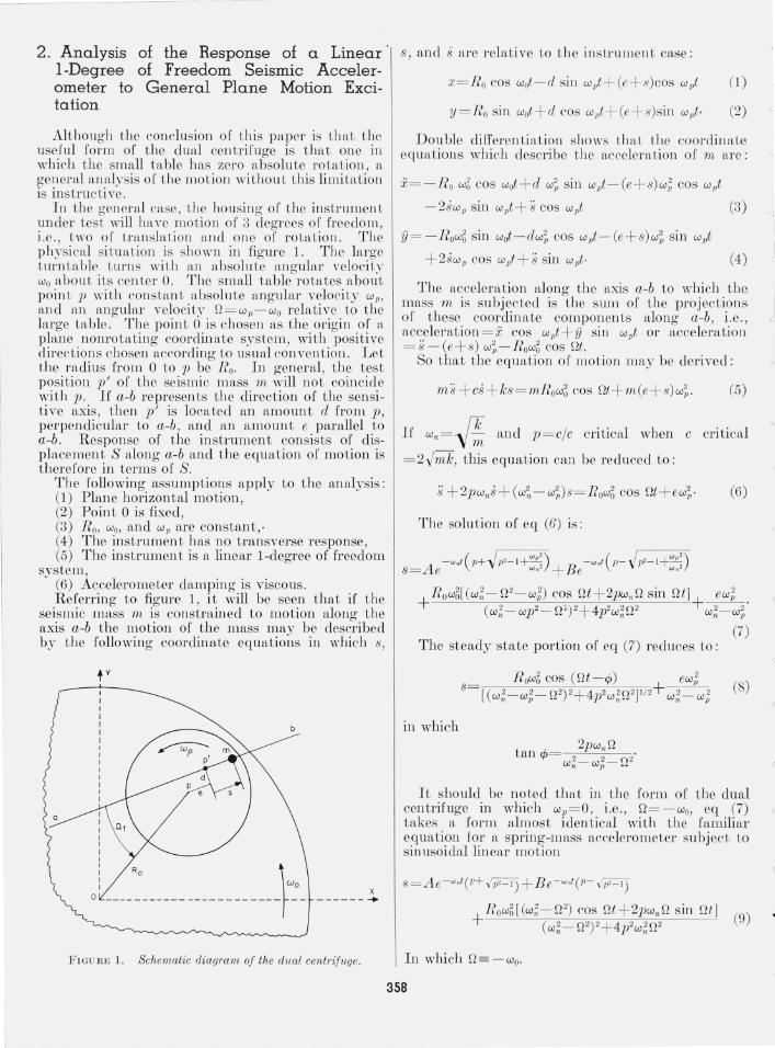
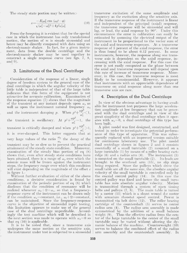
A pilo t model was first designed, constructed, and tested in order to investigate the potential performance of t his type of a pparaLus . This was subsequently replaced with an improved vcrs ion suitab le for con t inuou s laborato ry usc. The pilot model dual cen trifuge shown in figures 2 nnd ;) consists essentially of a smaJl t urntable (2) mounted on a hn'ge LUl'l1 table (1) oy means of a roller bearin g CILl'tridge (6) fend IL n tdius Ill'm (4) . The instrum ent (3) is mounted on the smnJl turn Ln,blc (2). lLs lends arc brought to the overhead a nn (15), no slip rings being required. Since th e pulleys which drive t he small table are all th e same s ize , the itbsolu tc anguhLr velo city of the small turntable is controlled only by th e coaxinJ control pulley (14) . ] 11 1,11 is CltSe the control pulley was fixed and hen ce the small tUl'lltable h as zero absolu te angubr velocity. 110tion is transmitted through a system of open timing belts and pulleys (7, 8) . The main t:tble is turned by a motor (11) which is a shun t wound cl-c lllotor with a.r mature rheostat speed co ntro l. Power is t ransmitted via belt drive (12) . T he roller beflring cartridge of th e countershaCt (5) serves to cen ter raelius arm (4). The mel ius arm assembly is made symmetrical by the addit ion oC a small b fdance weigh t (9) . Thus t he efl'eetive radius from the center oC t h e large turntable to the center of th e sm all t urntable m ay be varied without altering the dynamic balance of the m achine. Counterweight (10) serves to balance the combined effect of the radius arm assembly and the countershaft assembly. In
359
II
FIGURE 2.
preparation for a calibration, the accelerometer is balanced by adding an equal weigh t to the small counterbalance (9) and twice that to the large counterbalance (10). The whole assembly is supported by the machine frame (13).
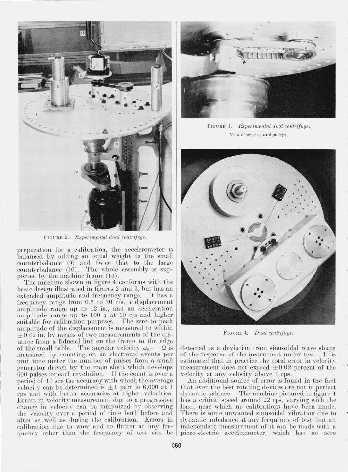
The machine shown in figure 4 conforms with the basic design illustrated in figures 2 and 3, but has an extended amplitude and frequency range. It has a frequency range from 0.5 to 30 cis, a displacement amplitude range up to 12 in. , and an acceleration amplitude range up to 100 g at 10 cis and higher suitable for calibration purposes. The zero to peak amplitude of the displacement is measured to within ± 0.02 in. by means of two measurements of the distan ce from a fiducial line on the frame to the edge of the sm all table. The angular velocity Wo= -n is measured by counting on an electronic events per unit t ime meter the number of pulses from a small generator driven by the main shaft which develops 600 pulses for each revolution. If the count is over a period of 10 sec the accuracy with whi ch the average velocity can be determined is ± 1 part in 6,000 at 1 rps and with better accuracies at higher velocities. Errors in velocity measurement due t o a progressive change in velocity can be minimized by observing the velocity over a period of t ime both before and after as well as during t he calibrat ion. Errors in calibration due to wow and to flutter at any frequen cy other than t he frequency of test can be
FIGURE 4. Dual centrifuge.
detected as a deviation from sinusoidal wave shape of the response of the instrument under test. It is estimated that in pract ice the total error in velocity measurement does not exceed ± 0.02 percent of the velocity at any velocity above 1 rps.
An additional source of error is found in the fact that even the best rotating devices are not in perfect dynamic balance. The machine pic tured in figure 4 has a critical speed around 22 rps, varying with the load, near which no calibrations h ave been made. There is some unwanted sinusoidal vibration due to dynamic unbalance at any frequency of test, but an independent measurement of it can be made with a piezo-electric accelerometer, which has no zero
360
\
d
'",
I ;,
(
""
10.0
1.0
.,; 5.0 ~ 4.0
~ 3.0
~ 2.0
~ 1.0
~ 7 .5 .4
3
.1
± 1/4 g
± I g
.2 .3 .4 .5 .7 1.0 2.0 4.0 6.0 10.0 20.0 40.0
FREQUE NCY ,CIS
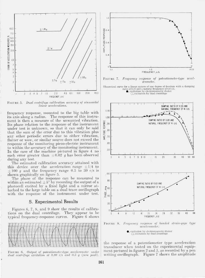
FIGURE 5. Dual centriJuge calibration aCCUTacy oj sinusoidal linear accelerations.
frequency response, mounted to the big table with its axis along a r::tdius. The response or this instrument is then a measure of the unwanted vibration. Its phase relation to the response of the instrument under test is unknown, so that it c::tn only be s::tid that the sum of the errol' due to this vibmtion plus any other periodic errors due to either vibration, flutter or wow, or similar source does not exceed the response of the monitoring piezo-electric instrument to within the accuracy or the monitoring instrument. In the case of the machine pictured in figure 4 no such error greater than ± 0.02 g has been observed during any test.
The estim::tted calibration accuracy attained with this device over the acceleration range ± 1/4 to ± 100 g and the frequency nmge 0.5 to 30 cis is shown graphically on figure 5.
The phase of the response can be measured to within an estimated ± 5° by recording the output of a pho tocell excited by a fixed light and a mirror att::tched to the large t::tble on a dual trace oscillograph with the response of the instrument under test.
5. Experimental Results
Figures 6, 7, 8, and 9 show the results of calibrations on the du::tl centrifuge. They appear to be typical frequency-response curves . Figure 6 shows
I-19
'-/-
F IGURE 6. Ou tput oj potentiometer-t ype accelerometer 1mder dual cent,<,ifuge excitation at 0.86 ci s and 0.5 g (zero peak).
" I
O.B
0. 6
0.4
OL 0. 1
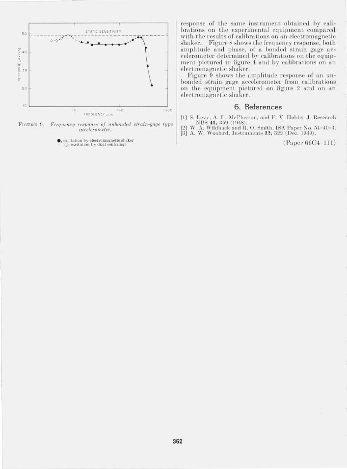
FIGURE 7.
o 0 0
1.0 FREQUENCY,c/s
T 10.0
Frequency res ponse oj potentiomeler·-type acceleromeler.
'TJlcorctical curve for a linear system of one degree of freedom wiih a damping ra tio of 0.75 and a na tura l freq uency of 6.0 cis.
1.10
1.00 ° 1.90
~ .80 = =
~ .70
.60
.50
e, excitation by electromagnetic shaker 0, excitation by dual centrifuge
DA MP ING RATIO OF 0.55 AND NATUR AL FREQUENCY OF 41 CIS ----;--;-,
DAMPING RATIO OF 0.60 AND NATURAL FREOUENCY OF 41 CIS
~ \
\ ... \ \ \ \ \ \
6 7 8 9 10 15 20 30 40 50 60
100 r---r---r---'---'---'---'---'---'---~--~--~
80
~ 40
20
11
DA~ PING RATIO OF 0.60 AND NATURAL FREQUENCY OF 41 CIS
16 20 24 28 FREOUENCY ,CIS
• •
•
32 36 40 44
FIG URE 8. FI'equency res ponse oj bonded stmin-gage type accelerometer.
• • excita tion hy electromagnetic shaker O. excitation by d ua l centrifuge
the response or a potentiometer type acceleration Lransducer when tested on the experimental equipm ent pictured in figures 2 and 3, as recorded by::t pen writing oscillograph . Figure 7 shows the amplitudc
361
50 STAT IC SENSITIVITY -- - ---~-:---- ------ - - - -- - - - - - - -- -
'" ~ 40
W if>
630 Cl.
~ a:
20
10 L-____________ ~ ____________ ~ ____________ ~
10 100 1000 FREQUENCY ,CIS
FIGURE 9. Frequency res ponse of unbonded s train-gage ty pe accelera meter.
e, excitation by electromagneti c shaker 0 , excitation by dual centrifuge
response of the same instrument obtained by calibrations on the experimental equipment compared with the results of calibrations on an electromagnetic shaker. Figure 8 shows the frequency response, both amplitude and phase, of tL bonded strain gage accelerometer determined by calibrations on the equipment pictured in figure 4 and by calibrn.tions on an electromagnetic shaker.
Figure 9 shows the amplitude response of an unbonded strain gage accelerometer from calibrations on the equipment pictured on figure 2 and on an electromagnetic shaker.
6. References [1) S. Levy, A. E. :V[cPherson, a nd E. V. Hobbs, J. Research
NBS 41, 359 (1948). [2) W. A. Wildhack and R. O. Smith, ISA Papcr No. 54- 40- 3. [3] A. VV. Woolard, Instruments n, 322 (Dce. 1939).
(Paper 6604-111)
362
J 1
I I
~